
A high resolution TOF-PET concept with axial geometry and...
8
A high resolution TOF-PET concept with axial geometry and digital SiPM readout C. Casella a , M. Heller b,n , C. Joram b , T. Schneider b a Institute for Particle Physics, ETH Zurich, CH-8093 Zurich, Switzerland b CERN, PH Department, CH-1211 Geneva, Switzerland article info Article history: Received 2 April 2013 Received in revised form 21 October 2013 Accepted 22 October 2013 Available online 29 October 2013 Keywords: Positron emission tomography PET TOF-PET LYSO Digital SiPM AX-PET abstract The axial arrangement of long scintillation crystals is a promising concept in PET instrumentation to address the need for optimized resolution and sensitivity. Individual crystal readout and arrays of wavelength shifter strips placed orthogonally to the crystals lead to a 3D-detection of the annihilations photons. A fully operational demonstrator scanner, developed by the AX-PET collaboration, proved the potential of this concept in terms of energy and spatial resolution as well as sensitivity. This paper describes a feasibility study, performed on axial prototype detector modules with 100 mm long LYSO crystals, read out by the novel digital Silicon Photomultipliers (dSiPM) from Philips. With their highly integrated readout electronics and excellent intrinsic time resolution, dSiPMs allow for compact, axial detector modules which may extend the potential of the axial PET concept by time of flight capabilities (TOF-PET). A coincidence time resolution of 211 ps (FWHM) was achieved in the coincidence of two axial modules read out by dSiPMs, fully maintaining the demonstrated performance of the AX-PET detector. & 2013 Published by Elsevier B.V. 1. Introduction Positron Emission Tomography (PET) relies on the coincident detection of the two 511 keV photons originating from electron– positron annihilation. Inorganic scintillator crystals read out by photodetectors are used in the majority of PET detectors. The precise measurement of the time difference between the arrival times of the two photons allows to improve the PET performance: the annihilation point along the line of response (LoR) can be constrained and the time coincidence window reduced, leading to noise reduction and improved contrast in the reconstructed images. This concept, known as Time Of Flight (TOF)-PET, is usually implemented with short crystals, typically shorter than a few cm, read out by photomultipliers or SiPMs. Coincidence time resolu- tions in the range 400–600 ps FWHM have been achieved so far in commercial PET scanners [1], corresponding to a spatial constraint along the LoR of about 6–9 cm. Higher timing resolution has been obtained with prototype detectors, relying on various geometrical arrangement of fast scintillators, either with PMT [2,3] or SiPM readout [4–8]. Alternative detector concepts for TOF-PET systems based on the prompt emission of Cherenkov light are also being investigated [9,10]. The Digital Silicon Photomultiplier (dSiPM) technology [11–14] developed by Philips is receiving a growing interest for a wide range of photon counting applications, from high energy physics to medical imaging. Their excellent intrinsic time resolution and their high level of integration, which leads to unprecedented compactness, make these devices very attractive for PET detector systems, and particu- larly for TOF-PET. The absence of afterpulses and the potentially reduced dark count rate are an additional plus. Recent studies on the coincidence timing resolution achieved with short crystals coupled to dSiPM show resolutions around 120 ps FWHM [15]. Over the past few years, the AX-PET collaboration has devel- oped a fully operational PET demonstrator [16], based on an axial geometrical approach: while in conventional PET systems, short scintillators point radially to the center of the tomograph, AX-PET uses long scintillator crystals (LYSO, 100 mm long, 3 3 mm 2 wide) which are arranged axially and stacked in several layers [17]. Arrays of wavelength shifter (WLS) strips are placed behind each layer of crystals. Hits in adjacent WLS strips define a cluster and its center of gravity provides the axial coordinate. Both the crystals and the WLS strips are individually read out by conven- tional SiPMs. Such a detector matrix allows for a 3D localization of the interactions of the 511 keV photons – both photoelectric absorption and Compton scattering – with good spatial resolution and sensitivity [18]. Two AX-PET detector modules have been constructed. They achieved competitive performance in terms of energy (ΔE=E 12%, FWHM, at 511 keV) and spatial resolution ( o2 mm, FWHM, in all 3 coordinates) [19]. Coincidence operation, Contents lists available at ScienceDirect journal homepage: www.elsevier.com/locate/nima Nuclear Instruments and Methods in Physics Research A 0168-9002/$ - see front matter & 2013 Published by Elsevier B.V. http://dx.doi.org/10.1016/j.nima.2013.10.049 n Corresponding author. Tel.: þ41 22 76 77786. E-mail address: [email protected] (M. Heller). Nuclear Instruments and Methods in Physics Research A 736 (2014) 161–168
Transcript of A high resolution TOF-PET concept with axial geometry and...

A high resolution TOF-PET concept with axial geometry and digitalSiPM readout
C. Casella a, M. Heller b,n, C. Joram b, T. Schneider b
a Institute for Particle Physics, ETH Zurich, CH-8093 Zurich, Switzerlandb CERN, PH Department, CH-1211 Geneva, Switzerland
a r t i c l e i n f o
Article history:Received 2 April 2013Received in revised form21 October 2013Accepted 22 October 2013Available online 29 October 2013
Keywords:Positron emission tomographyPETTOF-PETLYSODigital SiPMAX-PET
a b s t r a c t
The axial arrangement of long scintillation crystals is a promising concept in PET instrumentation toaddress the need for optimized resolution and sensitivity. Individual crystal readout and arrays ofwavelength shifter strips placed orthogonally to the crystals lead to a 3D-detection of the annihilationsphotons. A fully operational demonstrator scanner, developed by the AX-PET collaboration, proved thepotential of this concept in terms of energy and spatial resolution as well as sensitivity. This paperdescribes a feasibility study, performed on axial prototype detector modules with 100 mm long LYSOcrystals, read out by the novel digital Silicon Photomultipliers (dSiPM) from Philips. With their highlyintegrated readout electronics and excellent intrinsic time resolution, dSiPMs allow for compact,axial detector modules which may extend the potential of the axial PET concept by time of flightcapabilities (TOF-PET). A coincidence time resolution of 211 ps (FWHM) was achieved in the coincidenceof two axial modules read out by dSiPMs, fully maintaining the demonstrated performance of the AX-PETdetector.
& 2013 Published by Elsevier B.V.
1. Introduction
Positron Emission Tomography (PET) relies on the coincidentdetection of the two 511 keV photons originating from electron–positron annihilation. Inorganic scintillator crystals read out byphotodetectors are used in the majority of PET detectors. Theprecise measurement of the time difference between the arrivaltimes of the two photons allows to improve the PET performance:the annihilation point along the line of response (LoR) can beconstrained and the time coincidence window reduced, leading tonoise reduction and improved contrast in the reconstructedimages. This concept, known as Time Of Flight (TOF)-PET, is usuallyimplemented with short crystals, typically shorter than a few cm,read out by photomultipliers or SiPMs. Coincidence time resolu-tions in the range 400–600 ps FWHM have been achieved so far incommercial PET scanners [1], corresponding to a spatial constraintalong the LoR of about 6–9 cm. Higher timing resolution has beenobtained with prototype detectors, relying on various geometricalarrangement of fast scintillators, either with PMT [2,3] or SiPMreadout [4–8]. Alternative detector concepts for TOF-PET systemsbased on the prompt emission of Cherenkov light are also beinginvestigated [9,10].
The Digital Silicon Photomultiplier (dSiPM) technology [11–14]developed by Philips is receiving a growing interest for a wide rangeof photon counting applications, from high energy physics to medicalimaging. Their excellent intrinsic time resolution and their high levelof integration, which leads to unprecedented compactness, makethese devices very attractive for PET detector systems, and particu-larly for TOF-PET. The absence of afterpulses and the potentiallyreduced dark count rate are an additional plus. Recent studies on thecoincidence timing resolution achieved with short crystals coupled todSiPM show resolutions around 120 ps FWHM [15].
Over the past few years, the AX-PET collaboration has devel-oped a fully operational PET demonstrator [16], based on an axialgeometrical approach: while in conventional PET systems, shortscintillators point radially to the center of the tomograph, AX-PETuses long scintillator crystals (LYSO, 100 mm long, 3�3 mm2
wide) which are arranged axially and stacked in several layers[17]. Arrays of wavelength shifter (WLS) strips are placed behindeach layer of crystals. Hits in adjacent WLS strips define a clusterand its center of gravity provides the axial coordinate. Both thecrystals and the WLS strips are individually read out by conven-tional SiPMs. Such a detector matrix allows for a 3D localization ofthe interactions of the 511 keV photons – both photoelectricabsorption and Compton scattering – with good spatial resolutionand sensitivity [18]. Two AX-PET detector modules have beenconstructed. They achieved competitive performance in terms ofenergy (ΔE=E� 12%, FWHM, at 511 keV) and spatial resolution(o2 mm, FWHM, in all 3 coordinates) [19]. Coincidence operation,
Contents lists available at ScienceDirect
journal homepage: www.elsevier.com/locate/nima
Nuclear Instruments and Methods inPhysics Research A
0168-9002/$ - see front matter & 2013 Published by Elsevier B.V.http://dx.doi.org/10.1016/j.nima.2013.10.049
n Corresponding author. Tel.: þ41 22 76 77786.E-mail address: [email protected] (M. Heller).
Nuclear Instruments and Methods in Physics Research A 736 (2014) 161–168

followed by tomographic data analysis, resulted in parallax-errorfree reconstructed images of various phantoms and small animals(mice and rats) [20,21].
The work presented here focuses on experimental studieson 100 mm long axial crystals coupled to dSiPM photodetectors,as a proof of concept of an axial TOF-PET detector. The goal ofthe study is twofold. Firstly, it aims to demonstrate the feasibilityof combining the new dSiPMs with an AX-PET like detector design.For this purpose, two small scale prototypes were built andcharacterized, based on the same detector concept as the AX-PETdemonstrator, with crystals and WLS strips read out by dSiPMs.A critical aspect is the obtainable axial resolution which dependson the capability to read simultaneously relatively low light levelsfrom several adjacent WLS strips. As a second step, the studyexplores the achievable time resolution of an axial set-up withlong crystals read out on both sides by dSiPMs. The substantialpropagation time of the scintillation photons inside the longcrystals poses a particular challenge and the ultimate timeresolution is obtained by a mean-timing method, which requiresdual sided readout.
The paper is organized as follows: Section 2 describes theexperimental set-ups and methods. It includes a summary of themain characteristics of the used dSiPM photodetectors and theirmost relevant operational aspects. Section 3 focuses on the achievedlight yield and energy resolution from a simple test set-up, based ona single crystal. Section 4 is devoted to the full characterization ofthe two small scale modules based on the AX-PET detector concepts(“digital axial modules”), tested both individually and in coincidence.Timing measurements with two dual sided readout digital axialmodules are detailed in Section 5. Finally, Section 6 reports coin-cidence timing measurements with small crystals (3�3�3 mm3),for comparison.
2. Experimental set-ups and methods
The digital axial PET detector modules were based on the sameLYSO scintillator crystals and WLS strips as used in the AX-PETdemonstrator. The dimensions of the crystals were ð3� 3�100Þmm3 and of the WLS strips ð3� 0:9� 40Þmm3. For simplicityand cost reasons, the number of LYSO crystals per module wasreduced to four, mounted in a 2�2 arrangement.
The crystals were either read out by a dSiPM at one end only(Fig. 1(a)), or on both ends (Fig. 1(b)). In the first case, a reflectiveAluminium coating was deposited on the face opposite to thephotodetector, to maximize the light yield. Sixteen WLS strips,arranged in a 2�8 geometry, were placed orthogonally behind thecrystals with an air gap of 0.1 mm, covering only the central regionalong the axial direction. The LYSO crystals were not coated norwrapped in order to allow a fraction of the scintillation light toescape from the crystal and to be absorbed by the WLS stripsinterleaved with the crystals. The optical coupling of crystals andWLS strips to the dSiPMs was provided by optical grease (BicronBC-630). Behind each WLS strips layer, a white diffusive screenensured light yield maximisation in the WLS strips and opticalseparation from the next crystal layer. For the timing measure-ments with dual sided readout (Fig. 1(b)) the axial coordinate wasirrelevant and therefore the WLS strips were not readout, howeverleft in place. For a fair comparison with the single sided readoutset-up, the crystals were still not coated nor wrapped.
The modules were characterized with 511 keV annihilationphotons from two different types of 22Na sources: a “point-like”low activity source ðA¼ 178 kBq; ∅ 250 μmÞ, and a larger one,with higher activity ðA¼ 3:6 MBq; ∅ 5 mmÞ. The first one wasused for all spatial resolution studies, where the smallest beamspot is required; the stronger source was used for the timing
studies, where the spatial resolution is not crucial and a highercount rate is preferred to reduce the duration of the dataacquisition.
Prior to the coincidence measurements, the modules wereindividually characterized, in coincidence with a small scintillatorcrystal (LYSO, 3�3�3 mm3, painted with white diffusive paint)read out by another dSiPM, used to tag the 511 keV photons. Therequired coincidence between the module and the tagger allows toconfine the photon beam to a limited solid angle (defined by thesize of the tagging crystal and the relative distances betweentagger, source and module). Tagger and 22Na source were alignedon a two-axis translation station in front of the module, such thatthe collimated beam spot could scan different positions across thecrystals [19].
Temperature has a crucial impact on the operation of thedSiPMs, particularly in terms of dark count rate, as in most solidstate devices. The dSiPMs were mounted and thermally coupled toan Aluminum frame, through which water at 15 1C was circulatedin a buried channel.1 During operation, the measured temperatureon the dSiPMs was around 16.5 1C. The dSiPM used for the taggingcrystal could not be cooled due to mechanical constraints.
2.1. The dSiPM detectors
Digital SiPM photodetectors of type DPC 3200-22-44 [14] wereused for reading the light from the crystals andWLS strips. A dSiPM oftype DPC 6400-22-44 [14] was used for the readout of the taggingcrystal. Both types of detectors are arrays (also called tiles) of 8�8digital photodetectors (called pixels), each of dimension 3.2�3.9 mm2.Depending on the type of dSiPM detector, each pixel consists either of3200 or 6400 digital cells, operated in Geiger avalanche mode. The 64pixels are arranged on 16 identical units (called dies) of 4 pixels each.Each die operates independently from the others, although they are allconnected to the same FPGA on the backside of the tile and sharecommon services like e.g. the clock distributions. The discharged cellsare summed up on a pixel basis; the die is the smallest readout unit ofthe dSiPM array, providing the counts of detected photons in its fourpixels. Each die contains a pair of TDCs (19.5 ps time resolution) for thetime measurement of the first detected photon(s). The close proximityof the TDCs to the diodes results in excellent intrinsic timingresolution. The data acquisition of a die is started by a trigger,generated when the number of detected photons per pixel exceedsa predefined threshold. For triggering purposes, the pixel is subdividedinto four sub-pixels. The threshold can be set from one up to fourdetected photons. It is a statistical threshold, in the sense that itdepends on the distribution of the photons in the sub-pixels (e.g. fortrigger threshold equal to four, all four sub-pixels need to have at leastone hit). For trigger thresholds other than one, the required effectivenumber of fired cells is generally larger than the threshold value. Anyof the four pixels can trigger the die. A single timestamp per die isproduced when the trigger is satisfied. The readout of the die is startedonly if a second level trigger, the validation, is passed. As for the trigger,also the validation is a statistical threshold, which combines a thresh-old on the number of detected photons with their geometricaldistribution inside the pixel. The main purpose of the validation stepis to distinguish between scintillation events where the photon countwill rapidly increase, and thermally generated dark noise events. If thevalidation is not passed within a predefined validation time window(from 5 to 40 ns), all cells of the die are recharged and – once theoperation is completed – the die is ready to receive a new trigger. Ifthe event is validated, an integration period is started, where the
1 Although a lower operating temperature would have been more favourable,the operational temperature was chosen to avoid condensation in the non-controlled laboratory environment.
C. Casella et al. / Nuclear Instruments and Methods in Physics Research A 736 (2014) 161–168162

sensor waits and accumulates the incoming photons; at the end of theintegration, the readout process sums the discharged cells. Afterreadout, the cells are recharged and the die is ready for the nextacquisition. The entire acquisition cycle duration is largely dominatedby the readout time of 680 ns. Details of the dSiPM operation principleare provided in dedicated publications from Philips [11–14].
The data acquisition chain of the dSiPM detector is controlledby a state machine, implemented in the die and configurable by theFPGA. Its parameters (trigger and validation thresholds, durationof the various stages) are largely programmable. The achievableperformance of a set-up read by dSiPMs depends crucially on theoptimization of these settings for the respective measurement. Todevelop a thorough understanding of the various parameters andtheir interplay, a series of systematic tests was performed, inwhich the dSiPM tiles were exposed to light pulses from a LED. Adetailed report on these measurements is available as a CERNtechnical note [22].
To achieve the ultimate timing precision in a scintillationdetector, triggering on the first arriving photon is a commonlyapplied strategy. However, at ambient temperature, a low triggerthreshold of 1 or 2 photons generates a rate of dark triggers in thekHz/cell (MHz/pixel) range. Even if these triggers are not validated,they cause a recharging of the die entailing a dead time (durationof the recharge process, programmable from 20 to 80 ns) thatsignificantly reduces the die availability. This effect has a particularnegative impact if one needs to read simultaneously several dies,as is the case for the WLS strips readout for the axial coordinatedefinition. In order to optimize the sensors availability, the darkcount rate (DCR) must be minimized. The thermal generation ofdark hits is most effectively suppressed by lowering the tempera-ture. As in analog SiPMs, a temperature reduction by about 8 1Creduces the DCR by a factor of 2. Another action to reduce the DCRis to disable all unused cells that lie outside the footprint of acrystal or a WLS strip (see Fig. 1(c)). Those cells would contributeto the DCR, without having a chance to detect scintillationphotons. Disabling them reduces the average DCR and increasesthe global availability of the die, without any unwanted side effect.In addition, the DCR of every cell can be determined individuallyand the highest dark count cells can be disabled. As an example,
a reduction in the average DCR by 50% is observed when disablingthe 10% noisiest cells in the pixel, obviously also entailing a 10%reduction in photon detection efficiency. Studies of the perfor-mance of the dSiPM detectors at different percentages of disabledcells were done [22]. The measurements reported in the presentpaper were performed without any additional masking of thehighest dark count cells, maintaining the photon detection effi-ciency at its maximum.
The dSiPM acquisition is done in frames of 327 μs [14]. Withineach frame, the dies timestamps of all the tiles are synchronousallowing the offline building of the coincidences.
3. Light yield spectra and energy resolution
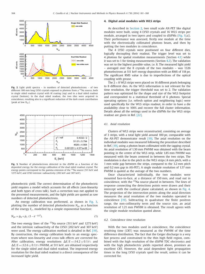
Prior to the measurements with the modules, a simple test setupwith one LYSO crystal was used to define the typical light yield andenergy resolution, both in the configuration of one single sidedreadout crystal (with Al coating) and with one crystal read out onboth sides by dSiPMs. Fig. 2 shows the raw light yield spectra of a22Na source placed close to the crystals, in terms of number ofdetected photoelectrons i.e. fired cells. In the dual sided readout case(Fig. 2, bottom) the light yield summed over the two tiles and theone recorded by one tile only are both shown. The direct comparisonof the one tile spectra demonstrates in first approximation the effectof the Al coating in increasing the light yield.
In order to get an estimate of the real number of photonsdetected by the dSiPM, the recorded light yield should be correctedboth for the non-linearity of the photodetectors (due to the limitednumber of cells), and for the cross talk effects. The cross talk isinduced by optical photons which are emitted from the Geigeravalanche in a cell. Those photons can provoke other avalanches inneighboring cells in the same pixel (inter-cells cross talk). At thesame time, they can also propagate through the crystal, and eitherbe detected by the photodetector, after reflection from the Al coating(for single sided readout crystals), or be detected by the oppositephotodetector (in the dual sided readout configuration). Both typesof cross talk – inter-cell and through-crystal cross talk – effectivelyincrease the number of detected fired cells, enhancing the true
Fig. 1. Sketches of the “digital axial modules”, with 4 LYSO crystals coupled to dSiPM photodetectors. (a) Single sided module used for the direct comparison with the AX-PETdemonstrator, consisting of 2 layers of 2 crystals and 8 WLS strips each. (b) Dual sided axial module. (c) Geometrical positioning of the crystals and strips in the dSiPM tile.Only the cells covered by the detectors are activated in the dSiPM tile.
C. Casella et al. / Nuclear Instruments and Methods in Physics Research A 736 (2014) 161–168 163
photoelectric yield. The correct determination of the photoelectricyield requires a model which accounts for all effects (non-linearityand both types of cross talk). Such a correction was not applied tothe presented measurements, and the light yields are quoted as rawnumbers of detected photoelectrons.
An energy calibration was performed, as shown in Fig. 3,plotting the number of detected photoelectrons Npe as a functionof the energy Eγ , modelled by a simple exponential function:
Npe ¼ p0þp1 ð1�e�p2EÞ: ð1Þ
The two energy lines of the 22Na source (511 keV and 1275 keV)and the intrinsic radioactivity of the LYSO (202 keV and 307 keV)were used. The energy calibration method is detailed in Ref. [19].By construction, the energy calibration leads to an energy spec-trum where non-linearity and cross talk effects are corrected for.After calibration, energy resolutions ΔE=E¼ ð14:270:1Þ% andΔE=E¼ ð12:670:1Þ% FWHM, at 511 keV, are obtained respectivelyfor the single sided and dual sided readout. The improved energyresolution for the dual sided readout is a direct consequence of theincreased light yield.
4. Digital axial modules with WLS strips
As described in Section 2, two small scale AX-PET like digitalmodules were built, using 4 LYSO crystals and 16 WLS strips permodule, arranged in two layers and coupled to dSiPMs (Fig. 1(a)).Their performance was assessed, firstly one module at the timewith the electronically collimated photons beam, and then byputting the two modules in coincidence.
The 4 LYSO crystals were positioned on four different dies,logically decoupling their readout. The trigger level was set to4 photons for spatial resolution measurements (Section 4.1) whileit was set to 1 for timing measurements (Section 4.2). The validationwas set to the highest possible value, i.e. 8. The measured light yield– averaged over the 8 crystals of the two modules – was 1326photoelectrons at 511 keV energy deposition with an RMS of 118 pe.The significant RMS value is due to imperfections of the opticalcoupling with grease.
The 2�8WLS strips were placed on 16 different pixels belongingto 8 different dies. As the WLS information is not relevant for thetime resolution, the trigger threshold was set to 2. The validationpattern was optimized for the shape and size of the WLS footprintand corresponded to a statistical threshold of 6 photons. Specialoperating options (i.e. refresh option and neighboring logic) wereused specifically for the WLS strips readout, in order to have a dieavailability close to 100% and recover the full cluster information.Details about all the settings used in the dSiPMs for the WLS stripsreadout are given in Ref. [22].
4.1. Axial resolution
Clusters of WLS strips were reconstructed, consisting on averageof 3 strips, with a total light yield around 100 pe, comparable withthe AX-PET demonstrator result [19]. The axial resolution on theindividual modules was measured following the procedure describedin Ref. [19], using a photon beam collimated with the tagging crystal.An axial resolution of 1.30 mm FWHM was obtained with the beampointing in the centre of the WLS strip, while 1.85 mm FWHM wasmeasured with the beam centered in between the two strips. Themodulation is due to the pitch in the WLS strips (4 mm pitch, with a1 mm wide gap between the strips, compared to the 3.2 mm pitchand 0.2 mm gap in AX-PET). A single module resolution of 1.57 mmFWHM is quoted as the average of the two numbers.
Once characterized individually, the two modules weremounted face-to-face, at a distance of 150 mm, and read out incoincidence, with the 22Na source placed in between. The lines ofresponse connecting the detections points were drawn and theirintercept with the confocal plane calculated, as shown in Fig. 4.The projection of the intersection points along the axial directionmeasures the axial resolution of the two modules operated incoincidence [19]. Subtracting in quadrature the finite positronrange, the non-collinearity term and the source size, an axialresolution of 1.21 mm FWHM is obtained. The result agrees withthe single module resolution quoted above.
4.2. Coincidence time resolution
With the two modules used in coincidence, the coincidenceresolving time (CRT) was measured as the FWHM of the timedifference distribution. The fact that the Geiger discharge is a veryfast process and constrained to the thin high field region, com-bined with the high resolution of the dSiPM TDC electronics andwith the high photoelectric yields reported above, promises anexcellent CRT. However, the axial dependent light propagationtimes in the long LYSO crystals spoil the result, unless it can becorrected for.
Npe
#E
vent
s
0
1000
2000
3000
4000
5000
6000Single Side Readout
one side
Npe
0 500 1000 1500 2000 2500 3000 3500 4000 4500
0 500 1000 1500 2000 2500 3000 3500 4000 4500
#E
vent
s
0500
10001500200025003000350040004500
Dual Side Readout
one side
two sides sum
Fig. 2. Light yield spectra – in numbers of detected photoelectrons – of twodifferent 100 mm long LYSO crystals exposed to photons from a 22Na source, bothin single sided readout crystal with Al coating (top) and in a dual sided readoutcrystal (bottom). In the dual sided readout, the two tiles were acquired incoincidence, resulting also in a significant reduction of the dark count contribution(peak at low Npe).
[keV]γ E0 200 400 600 800 1000 1200 1400
pe N
0
500
1000
1500
2000
2500
3000
3500
4000
4500
/ ndf 2χ 0.4332 / 20
p 5.794± 51.01 1
p 4.564± 4926 2
p 4.571e-06± 0.001251
/ ndf 2χ 0.4332 / 20
p 5.794± 51.01 1
p 4.564± 4926 2
p 4.571e-06± 0.001251
Fig. 3. Number of photoelectrons detected in the dSiPM as a function of thedeposited energy, for the energy calibration of the dual sided readout crystal. Theenergy points correspond to the gamma emission of the 22Na source (511 keV and1275 keV) and LYSO intrinsic radioactivity (202 keV and 307 keV).
C. Casella et al. / Nuclear Instruments and Methods in Physics Research A 736 (2014) 161–168164

Fig. 5 shows the time difference between pairs of crystals of thetwo modules, for all 16 combinations (4 crystals per module,2 modules, 4�4 possible pairs of coincidences). The same distribu-tion is shown both uncorrected and after correction for the axialcoordinate. Only the events with a photoelectric interaction in theaxial range which is covered by WLS strips are used for the CRTmeasurement. A CRT of � 406 ps FWHM prior to correctionimproves to � 274 ps FWHM after correction, in perfect agreementwith the value obtained from the average of the 16 crystal combina-tions, fitted independently: 274 ps FWHM with an RMS of 38 ps.
The time correction for the light path in the crystal was appliedon an event-by-event basis, relying on the axial coordinate informa-tion from the WLS strips. For each of the 16 crystal combinations,the time difference between the two modules ðΔtÞ was plottedversus the difference of the reconstructed axial coordinates ðΔzÞ, asshown in Fig. 6. The intercept p0 of the linear fit is related to aninternal time offset between the trigger networks of the respectivedies. The slope p1 represents the inverse of the effective lightpropagation speed s:
1p1
¼ s¼ kcn
ð2Þ
where c is the speed of light in vacuum, n is the LYSO refractiveindex (n¼1.8) and k is a geometrical factor. The latter expresses thefact that most of the photons do not propagate on a straight line butby bouncing repeatedly from the crystal sides. As a consequence, asmaller speed is obtained when projected along the crystal length(effective speed). Averaged over the 16 crystal combinations, a slopeof 7.5 ps/mm and an effective speed of about 0.13 mm/ps areobtained, corresponding to a geometrical factor k of 0.8.
5. Digital axial modules with dual sided readout
The dual sided readout of the scintillation crystals (Fig. 1(b))allows the calculation of a mean time per crystal, tm:
tm ¼ tupþtdown
2ð3Þ
which, by construction, is independent of the axial coordinate (upand down represent the two readout positions).
5.1. Dual sided module with tagger
The two dual sided readout modules were characterized, one atthe time, in coincidence with the tagging crystal. A total light yield– from the sum of the two readout sides – of about 2159photoelectrons with an RMS of 93 pe was measured, averagedover the 8 crystals of the two modules.
Fig. 7 shows the timing difference distribution for the four LYSOcrystals of the module, merged together, when the tagger is placedin the central axial position. A CRT of � 208 ps FWHM wasobtained from this merged distribution. The average of thecontribution of the four crystals treated separately gives a CRT ofð197713Þ ps FWHM.
The timing performance was studied as a function of the axialposition of the beam spot, as summarized in Fig. 8, confirming thatboth the module mean time and the CRT are independent ofthe axial coordinate, as expected. From the axial scan, a slope of� 7:5 ps=mmwas also extracted from the time difference betweenthe single side readout and the tagger (e.g. tup�ttag) as a functionof the axial coordinate. Equivalently, a slope of � 15 ps=mm ismeasured when the time difference between the two readoutsides (i.e. tup�tdown) is plotted versus the axial coordinate, with an
y [mm]-60 -40 -20 0 20 40 60
z [m
m]
-20
-15
-10
-5
0
5
10
15
20
0
200
400
600
800
1000
z [mm]-4 -3 -2 -1 0 1 2 3 4
#Eve
nts
0
200
400
600
800
1000Entries 15723
Constant 987.6
Mean 0.009383
Sigma 0.5638
Fig. 4. Left: drawing of the lines of response from the coincidence of two digital axial modules i.e. confocal (non-tomographic) reconstruction of the 22Na source. Right:projection along the axial (z) direction of the intersection of the lines of response with the central plane, as measurement of the axial spatial resolution.
Δ t [ns] -1 -0.5 0 0.5 1
#E
vent
s
0
200
400
600
800
1000
1200Corrected
Raw
Fig. 5. Time difference distribution for all the 16 crystal pairs merged together,both before and after timing correction. Only photoelectric events are selected.
Fig. 6. Example of light path calibration for one crystal combination.
C. Casella et al. / Nuclear Instruments and Methods in Physics Research A 736 (2014) 161–168 165
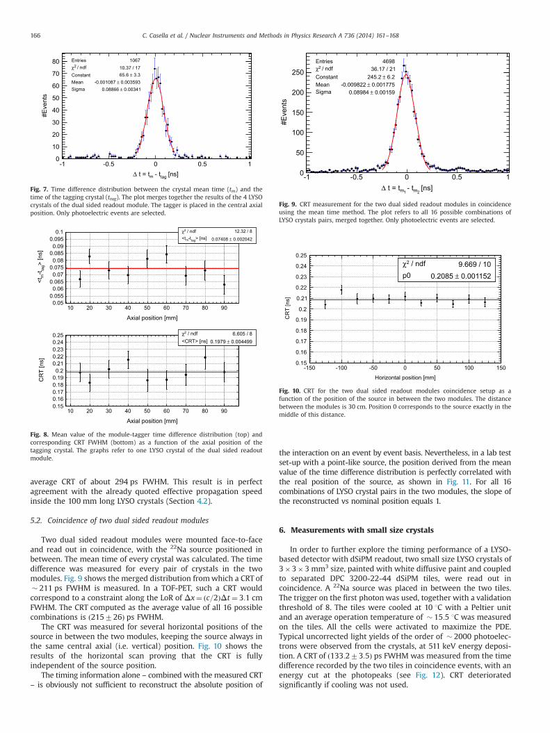
average CRT of about 294 ps FWHM. This result is in perfectagreement with the already quoted effective propagation speedinside the 100 mm long LYSO crystals (Section 4.2).
5.2. Coincidence of two dual sided readout modules
Two dual sided readout modules were mounted face-to-faceand read out in coincidence, with the 22Na source positioned inbetween. The mean time of every crystal was calculated. The timedifference was measured for every pair of crystals in the twomodules. Fig. 9 shows the merged distribution fromwhich a CRT of� 211 ps FWHM is measured. In a TOF-PET, such a CRT wouldcorrespond to a constraint along the LoR of Δx¼ ðc=2ÞΔt ¼ 3:1 cmFWHM. The CRT computed as the average value of all 16 possiblecombinations is ð215726Þ ps FWHM.
The CRT was measured for several horizontal positions of thesource in between the two modules, keeping the source always inthe same central axial (i.e. vertical) position. Fig. 10 shows theresults of the horizontal scan proving that the CRT is fullyindependent of the source position.
The timing information alone – combined with the measured CRT– is obviously not sufficient to reconstruct the absolute position of
the interaction on an event by event basis. Nevertheless, in a lab testset-up with a point-like source, the position derived from the meanvalue of the time difference distribution is perfectly correlated withthe real position of the source, as shown in Fig. 11. For all 16combinations of LYSO crystal pairs in the two modules, the slope ofthe reconstructed vs nominal position equals 1.
6. Measurements with small size crystals
In order to further explore the timing performance of a LYSO-based detector with dSiPM readout, two small size LYSO crystals of3�3�3 mm3 size, painted with white diffusive paint and coupledto separated DPC 3200-22-44 dSiPM tiles, were read out incoincidence. A 22Na source was placed in between the two tiles.The trigger on the first photon was used, together with a validationthreshold of 8. The tiles were cooled at 10 1C with a Peltier unitand an average operation temperature of � 15:5 1C was measuredon the tiles. All the cells were activated to maximize the PDE.Typical uncorrected light yields of the order of � 2000 photoelec-trons were observed from the crystals, at 511 keV energy deposi-tion. A CRT of ð133:273:5Þ ps FWHM was measured from the timedifference recorded by the two tiles in coincidence events, with anenergy cut at the photopeaks (see Fig. 12). CRT deterioratedsignificantly if cooling was not used.
[ns] tag - tm t = tΔ-1 -0.5 0 0.5 1
#E
vent
s
0
10
20
30
40
50
60
70
80
Fig. 7. Time difference distribution between the crystal mean time (tm) and thetime of the tagging crystal (ttag). The plot merges together the results of the 4 LYSOcrystals of the dual sided readout module. The tagger is placed in the central axialposition. Only photoelectric events are selected.
Axial position [mm]
> [n
s]ta
g-t
m <
t
0.050.0550.06
0.0650.07
0.0750.08
0.0850.09
0.0950.1
Axial position [mm]
10 20 30 40 50 60 70 80 90
10 20 30 40 50 60 70 80 90
CR
T [n
s]
0.150.160.170.180.190.2
0.210.220.230.240.25
Fig. 8. Mean value of the module-tagger time difference distribution (top) andcorresponding CRT FWHM (bottom) as a function of the axial position of thetagging crystal. The graphs refer to one LYSO crystal of the dual sided readoutmodule.
[ns] 2m - t
1m t = tΔ-1 -0.5 0 0.5 1
#E
vent
s
0
50
100
150
200
250
Fig. 9. CRT measurement for the two dual sided readout modules in coincidenceusing the mean time method. The plot refers to all 16 possible combinations ofLYSO crystals pairs, merged together. Only photoelectric events are selected.
Horizontal position [mm]
-150 -100 -50 0 50 100 150
CR
T [n
s]
0.15
0.16
0.17
0.18
0.19
0.2
0.21
0.22
0.23
0.24
0.25 / ndf 2χ 9.669 / 10
p0 0.001152± 0.2085
/ ndf 2χ 9.669 / 10p0 0.001152± 0.2085
Fig. 10. CRT for the two dual sided readout modules coincidence setup as afunction of the position of the source in between the two modules. The distancebetween the modules is 30 cm. Position 0 corresponds to the source exactly in themiddle of this distance.
C. Casella et al. / Nuclear Instruments and Methods in Physics Research A 736 (2014) 161–168166

7. Conclusions
Two different types of axial PET modules based on long LYSOcrystals with digital SiPM readout were built and characterized.The main results in terms of light yield and timing resolutions aresummarized in Table 1.
The measurements with two modules with single sided crystalreadout and WLS strips demonstrated the general feasibility of theaxial geometry, combined with the dSiPM readout, which requiresthe simultaneous readout of crystals and the associated clusters ofWLS strips. The performance of the digital module was demon-strated to be fully comparable to the analog module of the AX-PETdetector.
A moderate cooling and the optimization of the dSiPM opera-tional parameters allowed to operate the reduced scale modules inan efficient way. However, for a full scale AX-PET system whichrequires simultaneous availability of several readout channels, thecurrently available dSiPM sensors and readout kit would not leadto an adequate system sensitivity, mainly due to dark countsinduced dead time and the long readout sequence.
Excellent coincidence resolving times have been demonstratedwith short scintillation crystals (CRT � 130 ps FWHM), inwhich thefluctuations of the photon path length are of secondary importance.This is one of the most competitive timing measurements everachieved with LYSO, or the equivalent LSO [6–8,15]. The dSiPMexceeds the timing performance of the best photomultipliers and isat least fully competitive with analog SiPMs equipped with ultrafastreadout electronics. The digital concept with the TDCs integrated onthe die level allows for excellent intrinsic timing resolution andguarantees easy scalability without performance loss.
When long crystals are considered, high resolution CRT demandsan effective correction of the path length. A precise correction can bederived from the knowledge of the axial coordinate based on theWLS strip information. An even more powerful tool is the dual sidedreadout with the mean timing method, which, by construction,eliminates the axial dependence of the path length and leads toultimate timing performance. A CRT of 211 ps (FWHM), constantover the full field of view, constrains the annihilation point on theLoR to 3.1 cm (FWHM), proving the principle of an axial TOF-PETwith long crystals.
The result shows also that a novel positron emission imagingsystem, able to reconstruct the annihilation point along the LoRfrom TOF information alone (i.e. without the need of tomographicreconstruction), would still require a timing performance gainby one order of magnitude. Timing resolutions in the 10 ps rangewould also allow building an axial system with dual sided crystalreadout in which the axial coordinate is reconstructed withcompetitive precision from the time difference of the two ends.This would make the WLS strip arrays obsolete for the axialcoordinate definition and lead to a significant gain in simplicity,compactness and finally also cost effectiveness.
Acknowledgments
The experiments described in this paper are based on the axialPET concept developed by the AX-PET collaboration. We wouldlike to thank our technicians Miranda v. Stenis (CERN), MichaelDroege and Christian Haller (both ETH Zurich) for the competenttechnical support during the construction and operation of our
Δ-0.4 -0.3 -0.2 -0.1 0 0.1 0.2 0.3 0.4
#Eve
nts
/ 5 p
s
0
20
40
60
80
100
120
140 CRT = 133 ps FWHM
Fig. 12. CRT measurement using two 3�3 �3 mm3 LYSO crystals. The DLS 3200sensors are used with triggering on the first photon. Only photoelectric events areselected.
Table 1Summary of the LYSO light yield and timing resolution of the two digital axial modules set-ups (single sided readout with WLS strips, and dual sided readout). The moduleintrinsic timing resolution is extracted from the measured coincidence resolving time from the two modules used in coincidence. Also the energy resolution is reported inthe last column of the table, although extracted from a different setup of a single LYSO crystal not mounted in the module.
Module under test Light yield [pe] Measured CRT from coinc.setup [ps]
Module timing resolution[ps]
ΔE=EFWHM (511 keV)(single crystal) (%)
Mean RMS
Digital axial module with WLS strips 1326 118 274 (Fig. 5) 194 ð ¼ 274=ffiffiffi
2p
Þ 14.2
Digital axial module with dual sided readout 2159 93 211 (Fig. 9) 149 ð ¼ 211=ffiffiffi
2p
Þ 12.6
Horizontal position [mm]
-150 -100 -50 0 50 100 150
t) [m
m]
Δ×
(c/2
-150
-100
-50
0
50
100
150 / ndf 2χ 18.79 / 9
p0 0.3013± 6.386 p1 0.004012± 1
/ ndf 2χ 18.79 / 9p0 0.3013± 6.386 p1 0.004012± 1
Lyso pair combination
0 2 4 6 8 10 12 14 16
Slo
pe
0.950.960.970.980.99
11.011.021.031.041.05
/ ndf 2χ 20.9 / 15p0 0.001231± 0.9993
/ ndf 2χ 20.9 / 15p0 0.001231± 0.9993
Fig. 11. Top: mean value of the reconstructed coordinate from TOF ððc=2ÞΔtÞ vs thenominal position, for one possible combination of crystals pairs. Bottom: resultingslopes of the TOF-reconstructed versus true coordinates, for all possible 16crystals pairs.
C. Casella et al. / Nuclear Instruments and Methods in Physics Research A 736 (2014) 161–168 167
set-ups. The fruitful exchange with the experts from the PhilipsDigital Photon Counting team is greatly acknowledged: weare grateful to C. Degenhardt, T. Frach, Y. Haemisch, S. Reinartz,R. Schulze and B. Zwaans for advice and feedback. One of theauthors (M.H.) is Marie Curie fellow (MC-PAD network, GA214560).
References
[1] M. Conti, Eur. J. Nucl. Med. Mol. Imaging 38 (6) (2011) 1147.[2] W.W. Moses, et al., IEEE Trans. Nucl. Sci. NS-57 (3) (2010) 1570.[3] J.P. Lee, et al., Biomed. Eng. Lett. 1 (2011) 174.[4] S. Seifert, et al., Phys. Med. Biol. 57 (2012) 2219.[5] C.L. Kim, et al., IEEE Trans. Nucl. Sci. NS-56 (2009) 2580.[6] S. Seifert, et al., IEEE NSS MIC Conference Record (10.1109/NSSMIC.2009.5402260),
2009.[7] J.Y. Yeom, et al., Phys. Med. Biol. 58 (2013) 1207.
[8] S. Gundacker, et al., in: Proceedings of Science, International Workshop onNew Photon Detectors, LAL Orsay, France, 2012 ⟨http://pos.sissa.it/archive/conferences/158/016/PhotoDet%202012_016.pdf⟩.
[9] R. Dolenec, Time-of-flight positron emission tomography using Cherenkovradiation (Ph.D. thesis), University of Ljubljana, 2013.
[10] T. Ooba, et al., IEEE NSS Conference Record, 2004.[11] T. Frach, et al., IEEE NSS MIC Conference Record N28-005, 2009.[12] T. Frach, et al., IEEE NSS MIC Conference Record N58-001, 2010.[13] C. Degenhardt, et al., IEEE NSS MIC Conference Record (10.1109/NSSMIC.-
2010.5874115), 2011.[14] PDPC-TEK User Manual (v0.17), Philips Digital Photon Counting.[15] H.T. van Dam, Phys. Med. Biol. 58 (2013) 3243.[16] ⟨http://cern.ch/ax-pet ⟩.[17] J. Seguinot, et al., Il Nuovo Cimento C 29 (2005) 429.[18] A. Braem, et al., Nucl. Inst. Methods Phys. Res. A 586 (2008) 300.[19] P. Beltrame, et al., Nucl. Inst. Methods Phys. Res. A 654 (2011) 546.[20] E. Bolle, et al., IEEE NSS MIC Conference Record MIC22-5, 2011.[21] C. Joram et al., Imaging results and TOF studies with axial PET detectors,
Nuclear Instruments Methods in Physics Research A, ISSN. 0168–9002, http://dx.doi.org/10.1016/j.nima.2013.05.030.
[22] M. Heller, et al., CERN PH-EP-Tech-Note-2013-003, 2013.
C. Casella et al. / Nuclear Instruments and Methods in Physics Research A 736 (2014) 161–168168