A High-Performance Vision System for Obstacle · PDF fileA High-Performance Vision System for...
16
A High-Performance Vision System for Obstacle Detection Todd Williamson CMU-RI-TR-97-39 The Robotics Institute Camegie Mellon University Pittsburgh, Pennsylvania 15213 September, 1997 0 1997 Carnegie Mellon University This research was sponsored by the coliaborative agreement between Toyota Motor Cor- poration and Carnegie Mellon University.
Transcript of A High-Performance Vision System for Obstacle · PDF fileA High-Performance Vision System for...

A High-Performance Vision System for Obstacle Detection
Todd Williamson
CMU-RI-TR-97-39
The Robotics Institute Camegie Mellon University
Pittsburgh, Pennsylvania 15213
September, 1997
0 1997 Carnegie Mellon University
This research was sponsored by the coliaborative agreement between Toyota Motor Cor- poration and Carnegie Mellon University.
Abstract I have developed a method for obstacle detection in a highway environment using the CMU Video Rate Multi-Baseline Stereo Machine. One key feature of this method is the computation and output of a confidence measure at each pixel, so that regions of the scene with low reliability can be recognized and filtered out. This method has proven to be capable of detecting 3Oanhigh obstacles at distances of close to 100m. Unfortunately, the system requires significant of post-pro- cessing of the output data from the CMU stereo machine, and therefore cannot be run in real- time. Additionally, the design of the CMU stereo machine imposes several limitations on the sys- tem, both computationally (limited resolution, speed, and programmability) and practically (large size, cost, power consumption).
I propose to construct a system, consisting of both hardware and software, to perform this obsta- cle detection task in real-time. In the process, I will develop a general-purpose stereo vision machine that improves upon the state-of-the-art. Furthermore, I will show that the system can perfom obstacle detection in real-world environments and thus improve vehicle safety.

Table of Contents
1. Introduction 2. Related Work
3. Previous Work 4. Proposed Research 5. Conclusions 6. Schedule 7. Contributions 8. Acknowledgements 9. Bibliography
1 1 2
a 10
11
11
11 11

~ ~ ~~ ~~ ~~ ~
T<J& Wil1iumwi I'h. D. Thesi?, Proposul I
1 Introduction One important prohlem in the field of autonumuus navigation s y s t m s is that of obstacle detection. In the broadest krms. an obstacle is any region in the environment of the vehicle that should be avoided. In the Automated Highway Systems domain that is considered in this document. typical obstacles are other vehi- cles and debris that has fallen oilto the road surface. In some situations. it is also convenient to consider other objects. such as guard rails. as obstacles. These obstacles need to be detected at large distances ton the order of 50-100m) and with a high cycle rate (on the order of 10 Hz or better) to be useful for iniproving vehicle safety on the highway.
111 attacking thc problem ofdctzcting such obstacles. I h a w used the CMU Video-Rate Multi-Baselinc Ste- reo Machine. This machine has sonie unique features which inspired me to develop a new calibration nicth- od. The new calibration scheme extcnds the abilitics of the machiiie to include the detection of the deviation of objects from the cxpected planar environment. Using this algorithm to calihrate the stereo machine. and with some further post-processing oC the output of the machine. I haw been able to detect 3Ckm high ohsia- cles at ranges approaching 100m.
Unfortunately. this system has many limitations. Currently the posr-processing algorithms do not run in real-time. despite the fact that the output of the stereo machine is availablr at around 6 Hz. A large number of other limitations come from the stereo machine itself, including limited source image resolution. a limited number of possible disparity levels to search. limited calibration accuracy. and limited speed. Additionally. a number offactors render the stereo machine inappropriate for the AHS domain. including its size. power consumption. and high price.
Givcn these lirnirations. and the fact thar no other sterco vision processing hardware with suitable perfor- mance is commercially available. it seems natural tu propose to build a better stereo machine to use for oh- ~Laclcdetection in the AHS domain.
To build the best possible vision-based obstacle detection system. i t will be necessary to address the follow- ing issues:
hardware that is fast. while being modular and easily upgradable
low power consumption and small size
* low cost
* a stereo visirin algorithm specially tailored to the obstacle detection dornairi
high-speed implementation i n software
In investigating how it might be best to go about this. I have found that custom computing hardware, no matter how clever the design. is soon overtaken by the power of general-purpose CPUs. Therefore I propose to build a modular vision machine. with arbitrarily expandable (and upgradable) hardware. and the accorq- panying software, to perform the necessar). computation for stereo vision based obstacle detection.
The remainder of this paper is organized as follows. In Section 2 I will discuss related work in vision-based obstacle recognition, other obstacle detection systems. and stereo vision machines. In Section 3 1 will ex- plain in detail how I use the CMU stereo machine for obstacle dctection. In Section 4 I will discuss my pro- posed research. and in Sections 5 and 6 I will show my research schedule and thesis contributions.
2 Related Work Since this thesis touches on several areas. there is a large amount of related work. I havc divided the discus- Fion here into three areas: vision-based (including stereo) obstacle detection. obstacle detection using other sensors. and other stereo vision machines.

2.1 Vision-ba9ed obstacle detection There has been a lot of research on vision-based obstacle detection. Much of this work falls into two care- guries: induor static obstacles [ I ][?][7]. outdoor cross-country environment with static obstacles [ 15][18]. Since these systems are generally more concerned with detecting and navigating along a safe path than with speed. it is sufficient to detect obstacles at relatively close range a i d with slow cyclc timcs. Another class of systems deal with a highway environment and moving obstacles [4][13][14]. Most of these methods ai- tempt to detcct large obstacles such as other vehicles. but do not address the prohlems OF snialler salic ob- stacles.
One interesting system bastd o n stereo vision using I-D cameras is descrihed in [ S ] I h ] . They have demon- strated detecting a pedestrian crossing in front of the vehicle at short range.
2.2
A variety of other sensors have been u s 4 for obstacle detection. Radar and ladar (and to a lesscr extent so- oar) systems have been used for obstacle detection research for a numher of years. All o f these systems use a limited spectrum in which some possible obstacles may appear tnnspamnt. They are alsr susccptihle to multi-path reflection effects. Another concern for AHS applications is how to prevent intcrfererice betwcen the active signals from multiple vehicles travelling on the same roadway. While vision-based systems have their share of problems (chief among them being compulational complexity), the low cos1 nf camera sys- tems makes them an attractive option.
Obstacle Detection with other Sensors
2.3 Stereo Vision Machines A numher of groups have developed real-time stereo vision processing systems. In addition to the C M U sys- tem [ I I ] . groups at SRI [ 121. Cornel1 [23, and Point Grey Research [2 I ] among others have real-time stereo visicm systems. While all of these systems are very competitive with the CMU machine in terms ofperfor- mance and cost. they all lack one or more of the following useful features present in our machine: - multibaseline processing for incre.ased accuracy
the ability to use any arbitrary camera geometry - in particular long baselines and lorip focal
the ability to calibrate the machine for non-standard epipolar geumetry
length lenses
3 Previous Work During the past two semesters, I have developed a new algorithm for detecting obstacles using the CMU sterco machine and a modified epipolar geometry. In the following sections I will describe briefly the how CMU stereo machine works. a modified epipolar geometq and accompanying calibration scheme for ob- stacle detection. and some ideas about how the machine could he improved.
3.1 The CMU Video-Rate Multi-Baseline Stereo Machine
The CMU stereo machine consists of a number of custom-built 9U VME boards connected toeether in a system as shown in Figure 1. The system is described in more detail in [ I I]. The algorithm works by first digitizing the images from each of the cameras (up to 6 in the current design). The image is then passed through an 1 I x I I LOG (Laplacian of Gaussian) filter. The resulting data is then compressed to 4 hits by a non-linear weighting function. A11 suhsequent processing I s done with 4-hit pixel data.
The 4-bit LOG filtered data is then passed on to the geometry coinpensation unit. This unit is of particular importance because i t performs a very general transformation on each of the input images. the purpose of

Tridd Williumsrm Ph.D. Thesis Proprisd 3
Figure 1: Architecture of the CMU Stereo Machine
base image inspection image j Jins(i,i.C)
c c Add
Figure 2: Geometry compensation
which is to rectify the images before performing the SAD computation which comes next. For each postu- lated distance from the cameras, all of the images are effectively reprojected as if all objects in the scene were at that distance. This reprojection is accomplished via a 3-dimensional lookup table whose inputs are the postulated disparity 5 and the image coordinates (ij). and which outputs the corresponding image coor- dinate for each camera (I(i.j.<), J(i,j,<)l. The output image coordinates are given to sub-pixel accuracy (in 1116th~ of a pixel), and the four adjacent pixels are linearly interpolated to produce the reprojected result pixel. Note that the lookup table can actually contain any values whatsoever. so it is possible to correct for lens distortion. or to operate with one carncra upside down, or using cameras with different focal length lenses.
In the next stage, the absohte value of difference (AD) is performed pixel-by-pixel for the base camcra (camera # I ) paired with each ot'the other cameras. The results the AD computation are summed over each camera. resulting in a SAD (sum of absolute difference) value for each pixel for each disparity level.
The resulting SAD values are now smoothed by summing over a window whose size is programmable from 1x1 to 13x13. producing the SSAD. In the final stagc. for each pixel. the disparity level with the minimum

T d l CVilliumson P h D Thesis Prrqmsd 4
SSAD value is found. and the SSAD values of the minimun~ and its neighbors are sent to the CW DSP pro- cessing hoard. where the disparity levels can be interpolated for higher accuracy.
3.2 The Importance of Multi-Baseline Techniques
M y experiments with our three cameru system on the NavLah I 1 have convinced me of the usefulness of multiple baselines. Multi-baseline techniques provide at least three advantages:
I . disambiguation of repeating patterns
2. sensitivity to image texture in niultiple directions
3. improved accuracy. since all of the camcras contribute to the result
Since our cameras are currently mounted in a horizontal line. we don't see the advantage or#2 yet
Experiments with disconnecting individual cameras from the ste.reo machine while it i s operaling show that using ;ill three cameras in tandem produces significantly better results than when limited to any pair.
3 3 Stereo Calibration
In traditional stereo vision algorithms. the first stage of thc computation is to compute a disparity value at each pixel. For any pinel in one image. there is a single location where i t wculd project inti3 another image when observing a p i n t infinitely far away. The distance from that location at which the point ac~ually ap- pears is called the disparity. In this scenario. the planes of constant disparity are parallel to the reference image plane. and the distance to a point can be easily computed from its disparity.
This model does no1 necessarily map well onto the situation where the object to he observed i s a planar sur- face ihat i s not pwallel to the camera plane. In this case, pixels from different rows of the image are actually at different distances from the camera. Since in the AHS domain we expect to observe relatively tlat rclads with the occasional obstacle. it makes sense to rcdefifie disparity in such a way t h i t a constant disparity val- ue represents a single ground plane.
In the following sections. I will first describe the traditional calibration method Tor the CMU stereo ma- chine. and (hen describe two mudificarions of the algorithm to handle road geome.try hctter.
3.3.1 Traditional calibration scheme
The camera calibration problem for the CMU stereo machine consists primarily of measuring or computing the values that go into the lookup tables in the geometry compensation circuit. The stereo machine group has investigated a number of ways to do this, the most successful o f which uses ideas from weakly calibrated stereo research [18][17].
II is a well-known result that the homogeneous coordinates of corresponding points in two images of the same planar surface are related by 3 homography matrix (assuming a pinhole camera model) [19]. Further- more, given homography matrices for two parallel planes HTL and HI, at distances from the camera ;, and :2 respectively. the homograpby matrix for any other parallel plane dan he determined by simply interpo- lating the two homographiesr:

7fdd Wifliamron i‘h.D. Thesis t ‘r i ip~ol 5
This result has been used extensively to calibrate the stereu machine ar CMU. The stereo machinegroup has written an application that asks the user to choose 4 pairs of corresponding points (the minimum needed to compute a homography matrix? in two images. and a region of the image to match. The program then does a nonlinear optimization to match the two regions by finding the H matrix that minimizes the SSD between them. If we usc this program with. for cxample. images of a wall 1Om i n tront of the vchiclc and 100111 in front of the vehicle, then we can interpolate the hornography matrices thus ohtained. and generate the look- up tables for the geomctv compensation hardware to compute distance in front of the vehicle.
This algorithm effectively matches square templates from one image to the other. This is thc proper thing to do for surfaces that are parallel to the camera inlase plane. and in thosc cases i t produces \gery accurate results. In the highway environment. however. we expect the dominant portion orthe in1ag.e to he the road surface itself. When viewing the road surface, the distance to points in the image can t’aq greatly from one image row to the next. thus we expect a square region in the left image to map to a parallelogram-shaped regiun in the right image.
3.3.2 Road plane calibration schemes
In order to detwt obstacles in front ufthe vehicle. my idea was to use the same algorithm. hut with images taken in a slightly different manner. The first step is to treat the ground as if it were a planar surl‘ace. One possible second step could be to construct mother plane parallel to the ground planc. so that the two planes could be interpolated to generate a “height” map. While this approach works rcasonably well, it was very difficult to find a plane that is parallel to the ground. hut at a different height. Instead. i f we could take an image where all of the points were effectively infinitely fx away (compared to the distance between cam- eras). then it would he possible to compute thc homography for the “plane at infinity”. I n this case (;.=-). the equation simplifies to:
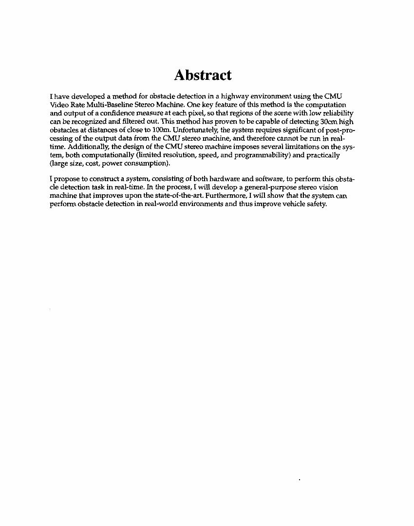
To get honiogmphies for H,, I pointed the cameras at the sky near the horizon. Using this method. I was able to generate the output image shown in Figure 3.
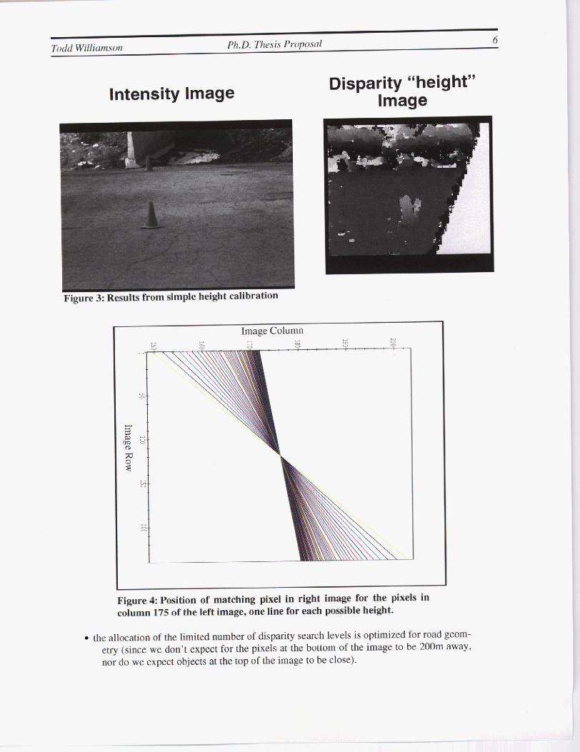
The results of simple height calibration were pretty good. hut as the image approaches the horizon. the re- sults get more and more noisy. This is due to the fact that the horizon line for parallel planes (the planes of constant height above the ground) i s always in the same location. Furthermore. for rows near the horizon line all different height levels appear at almost the same pixel location. at the bottom of the image difrerrnt height levels are very far apart in the image. and above the horizon, the disparity is negative. representing the fact that the plane is actually behind the camera (see Figure 4) .
Obviously. this type of heightcomputation has too many problems to be really practical. But is therea meth- od that captures the same template shape characteristics. while keeping the disparity levels distinguishable from each other? The answer seems to he yes. if we use the homography for the ground plane to determine the initial disparity levels. and then move in one pixcl increments dong the epiplar line. For an ideal cam- era configuration. the planes of constant “disparity” for this method are as shown in Figure 5.
This sampling method has a number of good properties:
the template shape is correct for ohjects that lie along one of these planes
the differenl planes are all distinct everywhere in the image
Intensity Image Disparity “height” Image
Image Column
Figure 4 Position of matching pixel in right image for the pixels in column 175 of the left image, one Line for each pobsible height.
the allocation of the limited number of disparity search levels is optimized for road geom- etry (since we don’t expect for the pixels at the bollom of the image to be 200m away, nor do we expect objects at the top of the image to be close).
. . . . .

7
I Distance (m)
Figure 5: Planes of constant “disparity” for the second calibration method. Parameters are l m baseline, 35mm lenses, 112” CCD, cameras aligned perfectly and 2m above the ground
even if the ground plane docs not match up with one of theconstant disparity planes cxactly (because of the curvature of the road and the fact that the bottom of the image may in iact bc very faraway tiom the vehiclc). a planar road surface must also he planar in (rowml- umn.disparity) space.
3.4 Confidence Measurement Even with a good camera calibration tailored to the t a k , there will always be regions of the world that lack sufficient texture to suppon a reliable depth measurement. One of thc most common ways to measure thc reliability of thc output of stereo matching is to look at the SSAD c u m as a function of disparity level. and to judge the “sharpness” of the minimum.
Unfortunately. in the CMU stereo machine, the image is passed through a LOG filter. the output of which is sensitive to the second derivative of the image iniensity. This computation is very susceptible to noise in the input image. and tends to amplify small image gradients. Thus the sharpness of the SSAD minimum can indicate whether or not there was any signal in the LOG filtered data. but it can’t indicate whether that aiglial was reliable or just an amplification of noise.
Therefore. a separate confidence metric i s necessary to determine the confidence of the output of the LOG filter. For this purpase. I have chosen to use the absolute value of the dcrivative of a gaussian filter. taken in the direction of the epiplar line in the image, and with the same parameters as the LOG filter. This con- fidence measure does the right thing intuitively - it roughly measures the amount of texture in the direction of the disparity search. Mathies [15J derives a similar metric for stereo matching.
Currently, this computation is done off-line on a UNlX workstation, and is one of the most tirnc-intensive pans of m y obstacle detection algorithm.
3.5 Further Post-Procwsing
The output from the CMU stereo machine using the above calibration method is a ?-dimensional image. where the value uf a pixel represents which of the planes resulted in the best match. From this output w e must decide which parts of the image represent obstacles and which parts represent road.

Todd Wiliium.wn Ph.D. Thais Prripiwal 8
Figure 6: An image of a parking lot, and the obstacle Image. Obstacles identified are marked in red. The blue-ish region was not processed.
Since planar surfaces in the world map to planar surfaces in this image representntion, the first step is to determine the ground plane. For this I use a simple Hough transform on the parameters of the plane. Of a set of possible candidate planes, the one for which the majority of pixels votes is assumed to he the ground plane. A method of this sort results in better rejection of outlier points than a simple least-squares fit.
Once the ground plane has been determined, obstacles can be detected by measuring the difference between h e output of the stereo machine and the best-fit plane. and thresholding. Further thresholding based on con- fidence produces an obstacle map such as that sbown in Figure 6. Note the traffic cone (in the green box) whose edges are detected by this algorithm. This traffic cone is approximately lOOm ahead of the vehicle, and is only about e r n high. Note also that the edges are not very well defined due to the 11x1 1 pixel smoothing window.
3.6 Disadvantages of the current system The system I have described so far is very promising, but it still has a number of problems. The post-pro- cessing i s very CPU-intensive, taking about 20 seconds per frame on a Sparcstation 5. Ideally, this post- pmcessing could be moved onto the stereo machine itself.
Additionally. the CMU stereo machine some drawbacks for use in the AHS domain:
too big - it uses a 9U VME cage
too power-hungry - it draws over400W
too expensive -our prototypes cost around $loOK each
* limited image size and number of possible disparity levels
It would alsa be nice to be able to freely program which portion of the image is used for computation as well as the number and range of candidate planes to be searched at each point as the machine is operating, for example to track an obstacle as it moves across the field of view. This sort of capability is not currently available on our machine.
4 Proposed Research My proposed research falls generally into two categories:
Developing a new stereo machine
Demonstrating its use for high-relibility long-range obstacle detection
. .

I intend to pertorm both parts of the research in parallel. and at my thesis defense. I should be able to show a complete. funcrioninp obstacle detection system based on the new machine.
4.1 I propose to solve each of the prohlems that 1 listed in Section 3.6. and hopefully improve performance as well. by developing a new stereo mac.hine.
In investigating how a new stereo machine can be built. 1 have found that the performance of general-pur- pose CPUs tends to improve exponentially, at my given time operating with clock rates that are several times faster than custom hardware which is availahlc (such as FPGGA technology). This fact suggests that the best approach to building a stereo machine might be to huild a modular system with replaceahlc CPU modules.
In Pact. there is a project at CMU; the Rmonfigurahle Vision Machine (RVM) project. that has been pro- ducing modular vision proccssing systems. The idea is that there is a baseboard with a number of slots. each of which has communication ports that can be wired arbitrarily. Each slot holds a vision processing module. which can be a DSP processor card. a digitizer. a convolver. etc.
I have been working together with the RVM project to evaluate a number of very fast CPUs that have come out recently. Our conclusion was that the Philips TriMedia TM-1000 is probably the fastest chip for vision processing at the moment. although the TI C60 is VKV close. The RVM lab is currently designing a CPU hoard for their machine based on this CPU.
My plan is to work with the RVM project to build any necessary hardware to handle the special conimuni- cation requirements of thc stereo algorithm At the same time. I will be developing the stereo machinc soft- ware in such a way that it will work with any number of CPU modules. and with prograinmabk image size and number of disparity levels.
One important feature that the current stereo machine is lacking is some measure of the confidence levcl of the output. I intend to implement the new stereo machine in such a way that theconfidence measure is avail- able in real-time. One area that deserves further attention is exactly what formula is appropriate for comput- ing this contidence measure. My approach of using a tuned derivative of &aussian filter. while it makes intuitive sense, was simply an ad-hoc procedure. I would like. to develop a more principled foniiula that combines elements of both image texture and the shape of the SSAD curve.
In order to get the stereo algorithm to run on a general-purpose CPU at reasonable speeds. a great deal of algorithmic optimizations will have to be made. In my experimentation with the Philips Trimedia simulator. I have found that it is possible to get large speedups (as much as SOX!) by inc.rementally adapting the algo- rithm to fit the types o f operations that the CPU can do quickly. In the processes. it is necessary to make trade-offs: for instance. the fastest way lo perform the geometry compensation would be to use a large look- up table. Unfortunately. the size of this lookup table would be around 20 megabytes per baseline. Since the memory for the lookup table would have to be very fast, and local to each processor in the system. this is not a viable solution. On the other hand. the most compact representation is the 8 floating-point numbers in the. homography matrix, but since the computation of image coordinates using the homography matrix in- volves a floating-point division, i t is very slow. Thus, some intermediate representation is necessary.
4.2 Improving and Validating the Obstacle Detection Algorithm Further experiments need to be done to validate the functioning of this obstacle detection algorithm in a va- riety ofcircumstances. 1 need to test the detectihility of various obstacles in different lighting conditions, at different disunces. on different road surfaces. and finally. under different weather conditions and at night.
Currently. I do not attempt to localize the detected obstacles in the 3-D. In order to be uset~l in a system. this needs to be done so that the vehicle can riike appropriate action. Also. no handling of negative obstacles
Developing a new Stereo Machine

Todd Wiliioirism Ph.D. Thhesii P r o p o d IO
(e& potholes) is currently done. though i t is a minor modification lo detect any visible regions of this sort of obstacle (though by their very nature. such regions iuust be small and therefore may not be detectable as obstacles).
Additionally. I want 10 experiment with differcnt spatial configurations ol the three cameras 10 dcterniine the effect on obstacle detection accuracy. I predict that accuracy will he significantly improved by arranging the cameras in a triangular configuration.
5 Conclusions The goal of this thesis is to build the best possible vision-based obstacle detectioii system. In order to do that, I intend to build a new stereo vision machine which will he better than every other contemporary sys- tem in at least one of (he following ways:
speed
modularity (both expandability and upgradability)
* cost - size
power consumption
accuracy
Additionally, I will develop an obstacle detection scheme using this machine which will he better than cur- rently available systems in the fullowing ways:
able to detect smaller obstacles ( ? O m or less) at greater distances (80-lWm)
* available coniidence metric to judge the reliability of the output
real-time. at least lofps

Todd \Villium,son P k D . Thrsis P r ~ i ~ i ~ ~ l I 1
6 Schedule
Summer 1997 t-- Fall 1997
I
I Summer 1998
7 Contributions
complete thesis proposal
RVM lab begins board design
validation experiments
experiment with different camera configurations
design stereo machine software in simulation
dcsign any necessary additional hardware
RVM lab finishes buard design
assemble and test hardware
finish developing and testing software
show operation o f stcreo machine
verify complete system operation
implement other vision algorithms
data collection
write thesis
defend
I expect to demonstrate the folluwing:
* a stereo vision machine that is cheap. compact, relatively low power. and completely mod- ular. with processing speed determined simply by the number of processors available
a Inelhod for intelligently tailoring the search spacc for multibaseline stereo to the obstacle detection problem.
a obstacle detection system based on the above machine and method. capable of detecting ?Ocm Clft) obstacles at distances of up to 80m reliably. and smaller objects at shorter ranges. - a modular. automatically conCigured software system to run on the machine
real-time computation of confidence level of disparity values
8 Acknowledgements This research way sponsored by the collaborative agreement hztween Toyota Motor Corporation and Car- negie Mellon University.
9 Bibliography [ I 1 N. Ancona. ''A Fast Obstacle Detection Method based on Optical Flow:' ~f'<JCt@&/lg,$ offhe Eunr-
peun Cnnferencz on Con~pulrr Visinii (ECCV '92). 1992.

M. Betke. E. Haritaoglu. and L. Davis. "Multiple Vehicle Detection and Tracking in Hard Real- Time." Procerdings of thr Inielligeiit Vehicles '96 Sjmposiuin. 1996.
S. Bohrer. M. Brauciimann. and W. von Seelen. "Visual Obstacle Detection by a Geometrically Sim- plified Optical Flow Approach." Proceedir1g.s ofthe fort7 Europem Cimfrrrnce (in Ar!(ficiul lntclli- g r n ~ ( K A I '92) . 1992.
S. Bnhrer. T. Zielkc, and V. Freiburg. "An Integrated Obstacle Detection Framework for Intelligent Cruise Control on Motorways." Proceedings ofthe Intelligent Vdiideu '95 S y ~ p m i u m . 1995.
J.-L. Bruyelle and J.-G. Postairc. "Direct Range Measurement by Linear Stereovision for Real-Time Obstacle Detection in Road Traffic." Proceedings of thc lnteniurioniil C'onti.r-etrcr on Zntelli~yerit Auiomimous Sy.s~em /(AS-3). 1993.
J.-C. Burie and J.-G. Postaire. "Enhancement of the Road Safety with a Stereovision System Based on Linear Camcras," Proceedin,qv rfrlie liirelligerit Vehicles '96 Synprisium. 1996.
S. Cornell. J. Pomll. J.E.W. Mayhew. "Ground Plane Obstacle Detection Under Variable Camera Geometry Using a Predictive Stereo Matcher." P i ~ ~ c e e d i n ~ . ~ of rhr British Mrrchinr Vision Corrfer- enie (RMVC '92). 1992.
W. Enkelmann. "Ohstaclc Detection by Evaluation of Optical Flow Fields rrom Image Sequences." lmujie ~lnd Vision Conymfiq ( U K ) . vol. 9. no. 3, June 1991.
V. Graefe and W. Efenberger. "A Novel Approach for the Detection of Vehicles on Freeways by Real-Time Vision." Procredings oJthr lntelligerit Vehicles '96 Symposium. 1996.
B . Heiselc and W. fitter. "Obstacle Detection Based on Color Blob Flow." Pt'<J(:rdLiifl,qS of the lntrl- ligrnt Vehicles '95 Synqinsiuni. 1995.
T. Kanade, A. Yoshida. K. Oda. H. Kano. and M. Tanaka "A Sterco Machine for Video Rate Dense Depth Mapping and its New Applications," Computer Vision und Putrurii Recoxiiitim Confivence (CVPR '961. June. 1996.
K. Konolige and B. Bolles. (SVM reference)http://www.ai .sri.com/-konolige//svm/indc~,html.
W. Kruper. W. Enkelmann, and S. Rossle. "Real-Time Estimation andTracking of Optical Flow Vec- tors fur Obstacle Detection." Proceedings rfthe Inrelligmi Vehicles '95 Symposium. 1995.
Q.T. Luong. J . Weber, D. Koller and J. Malik, "An integrated stereo-based approach to automatic vehicle guidance." F(frh International Crmference OII Coniprrter Vision (ICCV '95j, Cambridge. Mass. June 1995. pp. 52-57,
L . Mathies and P. Grandjean. "Stereo Vision for Planetary Rovers: Stochastic Modeling to Near Real- Time Implementation," Internaiionul Journal ofComputer Vision. 8: I , pp. 7 1-91. 1992.
L. Mathies, A. Kelly. T. Litwin. and G. Tharp. "Obstacle Detection fur Unmanned Ground Vehicles: A Progress Reportl" Proceedings of the Intelligent Vehicle3.7 '95 Symposium. 1995.
K. Oda. "Calibration Method for Multi-Camera Stereo Head for NavLab 11." Internal CMU Docu- ment. 1996.
L. Robert, M. Buffa. M. Ht5bcrt. "Weakly-Calibrated Stereo Perception for Rover Navigation." Prr~- ceedinw of the Intemutionul Corzference on Computer Vision (ICCV '95). 1995.
L. Robert, C. Zeller, 0. Faugeras, and M. Hebed. "Applications o f Nonmetric Vision to Some Visu- ally Guided Robotics Tasks." chapter from Visual Novigutiorz: From Rioloricul Swerns IO Unmunried Ground Vehicles, Lawrence Erlbaum Associates. 1997,

Todd Wiilianzson Ph. D. Th&v Propii.~al 13
[20] (Raven Project Reference)
[21] (Point Grey ResearcWriClops Reference) http://~ww.ptgrey.com/stereo/stereo.ht~nl
[221 J. Woodfill. (rcference for Cornell stereo machine).