
A heat energy recovery system from tunnel waste water
9
A heat energy recovery system from tunnel waste water 1 Nicholas Hytiris BSc, MSc, PhD Senior Lecturer, School of Engineering and Built Environment, Glasgow Caledonian University, Glasgow, UK 2 Konstantinos Ninikas BSc Associate Researcher, School of Engineering and Built Environment, Glasgow Caledonian University, Glasgow, UK (corresponding author: [email protected]) 3 Rohinton Emmanuel BSc, MSc, PhD Professor, School of Engineering and Built Environment, Glasgow Caledonian University, Glasgow, UK 4 Bjorn Aaen BSc, MEng Visiting Lecturer, School of Engineering and Built Environment, Glasgow Caledonian University, Glasgow, UK 5 Paul L. Younger BSc, MSc, PhD, FREng Professor, School of Engineering, University of Glasgow, Glasgow, UK 1 2 3 4 5 Minimising the maintenance costs of water ingress in transportation tunnels is a significant challenge. Decreasing the overall cost of a ground source heat pump system is equally challenging. An effort to address both issues at once has been made in relation to groundwater ingress in the Glasgow Subway system. Inflowing water is a valuable resource which could be channelled through a water source heat pump (WSHP) to produce heat energy for domestic or public use (heating and domestic hot water). Water flow and water temperature have been recorded for a year at 21 different points within the network of the underground tunnels and platforms. The points of highest water influx were identified, and the heat energy content of each has been calculated. Working from these data, several options were identified for capturing the water and diverting it to a WSHP to recover heat. A final design for a pilot system within the tunnels was developed. The findings of this study are expected to contribute a renewable heat solution through a cost-effective heat pump system design. Notation COP H coefficient of performance E required energy: kW G heat energy flux: kW H total heating effect S VC specific heat capacity of water: J/(l K) Z flow rate: l/s Dq temperature drop: °C r density of water: kg/m 3 Introduction The need for finding alternative sources to replace conventional fuel is becoming more and more urgent. The basic factors that have led the UK government to favour more environment-friendly methods of heating are the obligation of reducing the carbon dioxide (CO 2 ) emissions to the 1990s’ levels by 2020 (Scottish Government, 2012) and to reduce fully the carbon dioxide emissions of heating by 2050 (Climate Change Act 2008, 2008). Ground source heat pump (GSHP) systems have shown the potential to reduce energy consumption, and as a result, a carbon dioxide reduction (Ground Source Heat Pump Association, 2015) compared with conventional heating systems (electricity, oil, gas). Heat pumps have long been a key technology for exploiting low- grade heat. They use compression (the same principle as a refrigerator) to extract tepid low-grade heat to produce heat for space and/or water heating in general (NRC, 2015). They can also be reversed to produce cooling. Heat pumps are designed to move thermal energy opposite to the direction of spontaneous heat flow by absorbing heat from a cold space and releasing it to a warmer one. A typical heat pump uses less energy input (compared to all other conventional heating means, e.g. gas and petrol) to accomplish the work of transferring energy from the heat source (aquifer) to the destination for space heating/hot water (Branz, 2015). This study has investigated the possibility of harvesting heat from the water ingress inside Glasgow’ s Subway tunnels by using a heat pump. The Glasgow Subway is a circular underground passenger railway system in the centre and west of the city. It contains twin tunnels, allowing clockwise circulation of trains on the ‘outer ’ circle and anticlockwise on the ‘inner’ circle. Fifteen stations are distributed along the route length of just over 10 km. The River Clyde dissects the circular route, with eight stations north of the river and seven to the south, as shown in Figure 1. 300 Cite this article Hytiris N, Ninikas K, Emmanuel R, Aaen B and Younger PL (2018) A heat energy recovery system from tunnel waste water. Environmental Geotechnics 5(5): 300–308, https://doi.org/10.1680/jenge.15.00087 Research Article Paper 1500087 Received 14/12/2015; Accepted 16/08/2016 Published online 02/09/2016 ICE Publishing: All rights reserved Keywords: energy/geomorphology/ town & city planning Environmental Geotechnics Downloaded by [ Glasgow University Library] on [25/10/18]. Copyright © ICE Publishing, all rights reserved.
Transcript of A heat energy recovery system from tunnel waste water

Cite this articleHytiris N, Ninikas K, Emmanuel R, Aaen B and Younger PL (2018)A heat energy recovery system from tunnel waste water.Environmental Geotechnics 5(5): 300–308,https://doi.org/10.1680/jenge.15.00087
Research ArticlePaper 1500087Received 14/12/2015; Accepted 16/08/2016Published online 02/09/2016
ICE Publishing: All rights reserved
Keywords: energy/geomorphology/town & city planning
Environmental Geotechnics
Download
A heat energy recovery systemfrom tunnel waste water
1 Nicholas Hytiris BSc, MSc, PhD300ed by
Senior Lecturer, School of Engineering and Built Environment,Glasgow Caledonian University, Glasgow, UK
2 Konstantinos Ninikas BSc
Associate Researcher, School of Engineering and Built Environment,Glasgow Caledonian University, Glasgow, UK (corresponding author:[email protected])[ Glasgow University Library] on [25/10/18]. Copyright © ICE Publishing
3 Rohinton Emmanuel BSc, MSc, PhD
, all
Professor, School of Engineering and Built Environment, GlasgowCaledonian University, Glasgow, UK
4 Bjorn Aaen BSc, MEng
Visiting Lecturer, School of Engineering and Built Environment,Glasgow Caledonian University, Glasgow, UK5 Paul L. Younger BSc, MSc, PhD, FREng
Professor, School of Engineering, University of Glasgow, Glasgow, UK1 2 3 4 5
Minimising the maintenance costs of water ingress in transportation tunnels is a significant challenge. Decreasing
the overall cost of a ground source heat pump system is equally challenging. An effort to address both issues at
once has been made in relation to groundwater ingress in the Glasgow Subway system. Inflowing water is a
valuable resource which could be channelled through a water source heat pump (WSHP) to produce heat energy for
domestic or public use (heating and domestic hot water). Water flow and water temperature have been recorded for
a year at 21 different points within the network of the underground tunnels and platforms. The points of highest
water influx were identified, and the heat energy content of each has been calculated. Working from these data,
several options were identified for capturing the water and diverting it to a WSHP to recover heat. A final design
for a pilot system within the tunnels was developed. The findings of this study are expected to contribute a
renewable heat solution through a cost-effective heat pump system design.
NotationCOPH coefficient of performanceE required energy: kWG heat energy flux: kWH total heating effectSVC specific heat capacity of water: J/(l K)Z flow rate: l/sDq temperature drop: °Cr density of water: kg/m3
IntroductionThe need for finding alternative sources to replace conventionalfuel is becoming more and more urgent. The basic factors thathave led the UK government to favour more environment-friendlymethods of heating are the obligation of reducing the carbondioxide (CO2) emissions to the 1990s’ levels by 2020 (ScottishGovernment, 2012) and to reduce fully the carbon dioxideemissions of heating by 2050 (Climate Change Act 2008, 2008).Ground source heat pump (GSHP) systems have shown thepotential to reduce energy consumption, and as a result, a carbondioxide reduction (Ground Source Heat Pump Association, 2015)compared with conventional heating systems (electricity, oil, gas).
Heat pumps have long been a key technology for exploiting low-grade heat. They use compression (the same principle as arefrigerator) to extract tepid low-grade heat to produce heat forspace and/or water heating in general (NRC, 2015). They can alsobe reversed to produce cooling. Heat pumps are designed to movethermal energy opposite to the direction of spontaneous heat flowby absorbing heat from a cold space and releasing it to a warmerone. A typical heat pump uses less energy input (compared to allother conventional heating means, e.g. gas and petrol) toaccomplish the work of transferring energy from the heat source(aquifer) to the destination for space heating/hot water (Branz,2015).
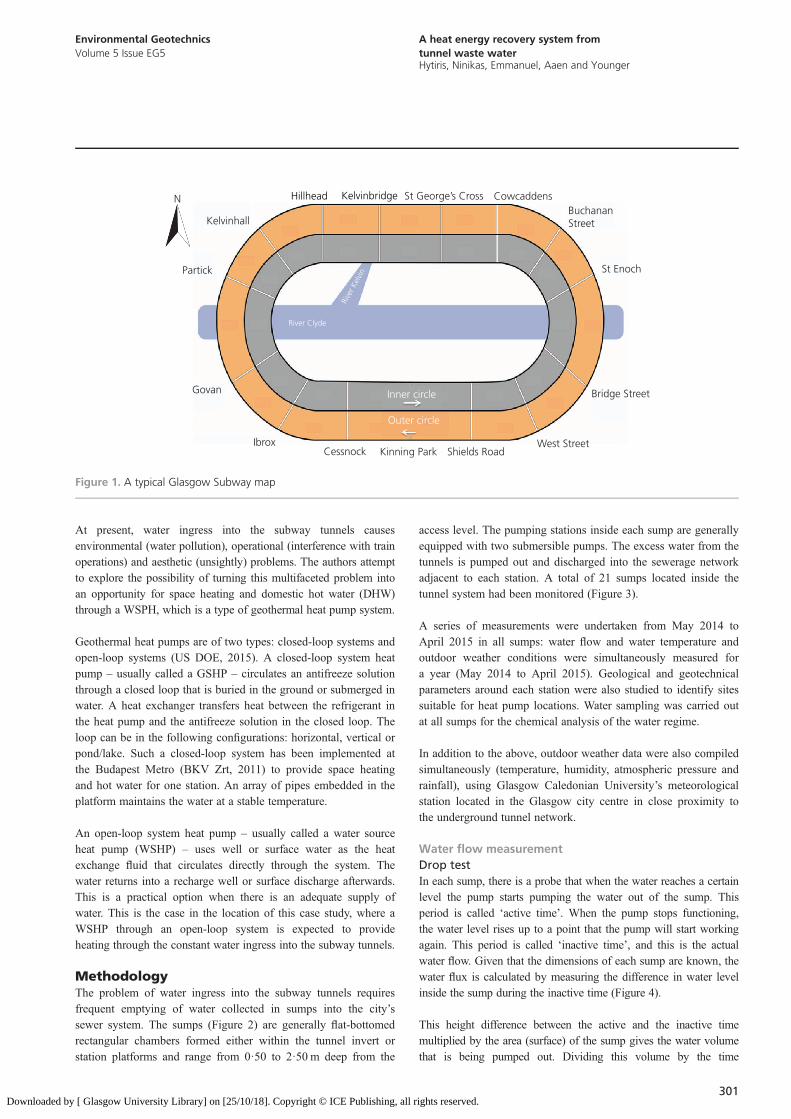
This study has investigated the possibility of harvesting heat fromthe water ingress inside Glasgow’s Subway tunnels by using aheat pump. The Glasgow Subway is a circular undergroundpassenger railway system in the centre and west of the city. Itcontains twin tunnels, allowing clockwise circulation of trains onthe ‘outer’ circle and anticlockwise on the ‘inner’ circle. Fifteenstations are distributed along the route length of just over 10 km.The River Clyde dissects the circular route, with eight stationsnorth of the river and seven to the south, as shown in Figure 1.
rights reserved.
Environmental GeotechnicsVolume 5 Issue EG5
A heat energy recovery system fromtunnel waste waterHytiris, Ninikas, Emmanuel, Aaen and Younger
Downloaded by
At present, water ingress into the subway tunnels causesenvironmental (water pollution), operational (interference with trainoperations) and aesthetic (unsightly) problems. The authors attemptto explore the possibility of turning this multifaceted problem intoan opportunity for space heating and domestic hot water (DHW)through a WSPH, which is a type of geothermal heat pump system.
Geothermal heat pumps are of two types: closed-loop systems andopen-loop systems (US DOE, 2015). A closed-loop system heatpump – usually called a GSHP – circulates an antifreeze solutionthrough a closed loop that is buried in the ground or submerged inwater. A heat exchanger transfers heat between the refrigerant inthe heat pump and the antifreeze solution in the closed loop. Theloop can be in the following configurations: horizontal, vertical orpond/lake. Such a closed-loop system has been implemented atthe Budapest Metro (BKV Zrt, 2011) to provide space heatingand hot water for one station. An array of pipes embedded in theplatform maintains the water at a stable temperature.
An open-loop system heat pump – usually called a water sourceheat pump (WSHP) – uses well or surface water as the heatexchange fluid that circulates directly through the system. Thewater returns into a recharge well or surface discharge afterwards.This is a practical option when there is an adequate supply ofwater. This is the case in the location of this case study, where aWSHP through an open-loop system is expected to provideheating through the constant water ingress into the subway tunnels.
MethodologyThe problem of water ingress into the subway tunnels requiresfrequent emptying of water collected in sumps into the city’ssewer system. The sumps (Figure 2) are generally flat-bottomedrectangular chambers formed either within the tunnel invert orstation platforms and range from 0·50 to 2·50 m deep from the
[ Glasgow University Library] on [25/10/18]. Copyright © ICE Publishing, all r
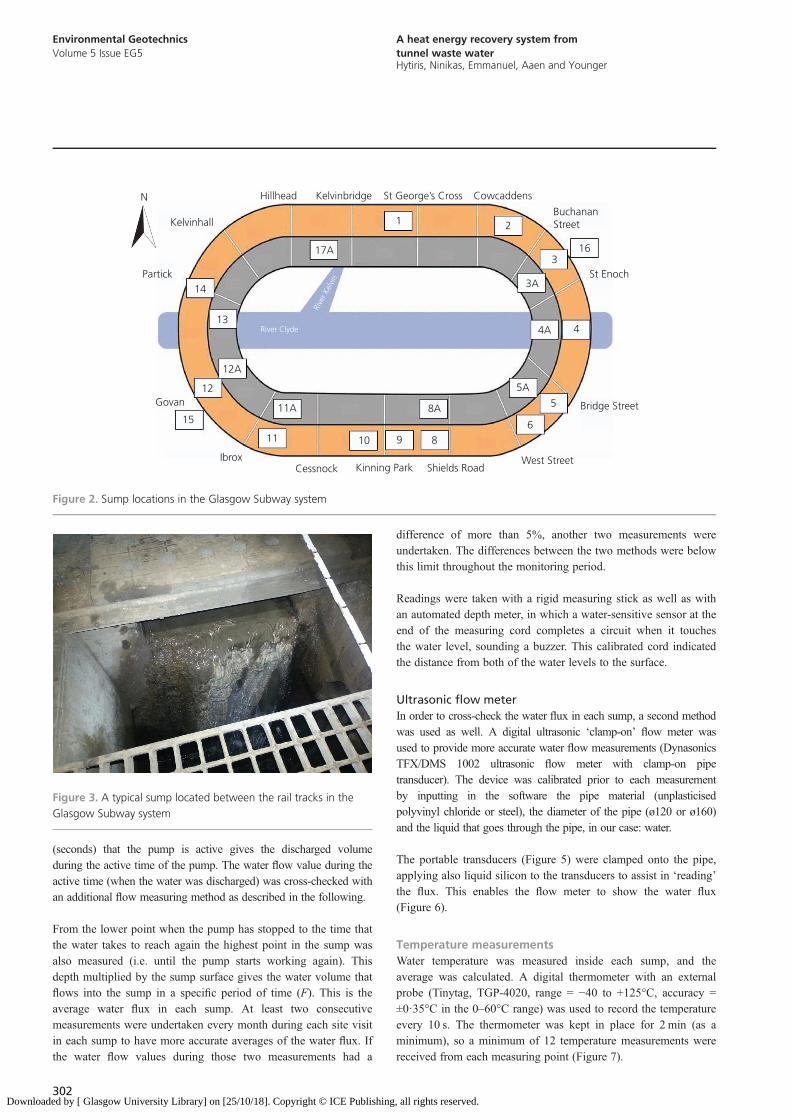
access level. The pumping stations inside each sump are generallyequipped with two submersible pumps. The excess water from thetunnels is pumped out and discharged into the sewerage networkadjacent to each station. A total of 21 sumps located inside thetunnel system had been monitored (Figure 3).
A series of measurements were undertaken from May 2014 toApril 2015 in all sumps: water flow and water temperature andoutdoor weather conditions were simultaneously measured fora year (May 2014 to April 2015). Geological and geotechnicalparameters around each station were also studied to identify sitessuitable for heat pump locations. Water sampling was carried outat all sumps for the chemical analysis of the water regime.
In addition to the above, outdoor weather data were also compiledsimultaneously (temperature, humidity, atmospheric pressure andrainfall), using Glasgow Caledonian University’s meteorologicalstation located in the Glasgow city centre in close proximity tothe underground tunnel network.
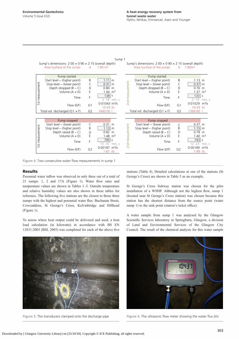
Water flow measurementDrop testIn each sump, there is a probe that when the water reaches a certainlevel the pump starts pumping the water out of the sump. Thisperiod is called ‘active time’. When the pump stops functioning,the water level rises up to a point that the pump will start workingagain. This period is called ‘inactive time’, and this is the actualwater flow. Given that the dimensions of each sump are known, thewater flux is calculated by measuring the difference in water levelinside the sump during the inactive time (Figure 4).
This height difference between the active and the inactive timemultiplied by the area (surface) of the sump gives the water volumethat is being pumped out. Dividing this volume by the time
Hillhead Kelvinbridge St George’s Cross Cowcaddens
Kelvinhall
Partick
Govan
IbroxCessnock Kinning Park Shields Road
West Street
Bridge Street
St Enoch
BuchananStreet
Inner circle
Outer circle
River Clyde
Rive
r Kel
vin
N
Figure 1. A typical Glasgow Subway map
301ights reserved.
Environmental GeotechnicsVolume 5 Issue EG5
A heat energy recovery system fromtunnel waste waterHytiris, Ninikas, Emmanuel, Aaen and Younger
Download
(seconds) that the pump is active gives the discharged volumeduring the active time of the pump. The water flow value during theactive time (when the water was discharged) was cross-checked withan additional flow measuring method as described in the following.
From the lower point when the pump has stopped to the time thatthe water takes to reach again the highest point in the sump wasalso measured (i.e. until the pump starts working again). Thisdepth multiplied by the sump surface gives the water volume thatflows into the sump in a specific period of time (F). This is theaverage water flux in each sump. At least two consecutivemeasurements were undertaken every month during each site visitin each sump to have more accurate averages of the water flux. Ifthe water flow values during those two measurements had a
302ed by [ Glasgow University Library] on [25/10/18]. Copyright © ICE Publishing
difference of more than 5%, another two measurements wereundertaken. The differences between the two methods were belowthis limit throughout the monitoring period.
Readings were taken with a rigid measuring stick as well as withan automated depth meter, in which a water-sensitive sensor at theend of the measuring cord completes a circuit when it touchesthe water level, sounding a buzzer. This calibrated cord indicatedthe distance from both of the water levels to the surface.
Ultrasonic flow meterIn order to cross-check the water flux in each sump, a second methodwas used as well. A digital ultrasonic ‘clamp-on’ flow meter wasused to provide more accurate water flow measurements (DynasonicsTFX/DMS 1002 ultrasonic flow meter with clamp-on pipetransducer). The device was calibrated prior to each measurementby inputting in the software the pipe material (unplasticisedpolyvinyl chloride or steel), the diameter of the pipe (ø120 or ø160)and the liquid that goes through the pipe, in our case: water.
The portable transducers (Figure 5) were clamped onto the pipe,applying also liquid silicon to the transducers to assist in ‘reading’the flux. This enables the flow meter to show the water flux(Figure 6).
Temperature measurementsWater temperature was measured inside each sump, and theaverage was calculated. A digital thermometer with an externalprobe (Tinytag, TGP-4020, range = −40 to +125°C, accuracy =±0·35°C in the 0–60°C range) was used to record the temperatureevery 10 s. The thermometer was kept in place for 2 min (as aminimum), so a minimum of 12 temperature measurements werereceived from each measuring point (Figure 7).
Hillhead Kelvinbridge St George’s Cross Cowcaddens
1 2
17A3
16
BuchananStreet
St Enoch3A
4A 4
5A
5
6
8A
8910
Bridge Street
West StreetShields RoadKinning ParkCessnock
11
11A
Ibrox
15
12
12A
Govan
13
14Partick
Kelvinhall
River Clyde
Rive
r Kel
vin
N
Figure 2. Sump locations in the Glasgow Subway system
Figure 3. A typical sump located between the rail tracks in theGlasgow Subway system
, all rights reserved.
Environmental GeotechnicsVolume 5 Issue EG5
A heat energy recovery system fromtunnel waste waterHytiris, Ninikas, Emmanuel, Aaen and Younger
Downloaded by
ResultsPerennial water inflow was observed in only three out of a total of21 sumps: 1, 2 and 17A (Figure 1). Water flow rates andtemperature values are shown in Tables 1–3. Outside temperatureand relative humidity values are also shown in these tables forreference. The following five stations are the closest to those threesumps with the highest and perennial water flux: Buchanan Street,Cowcaddens, St George’s Cross, Kelvinbridge and Hillhead(Figure 1).
To assess where heat output could be delivered and used, a heatload calculation (in kilowatts) in accordance with BS EN12831:2003 (BSI, 2003) was completed for each of the above five
[ Glasgow University Library] on [25/10/18]. Copyright © ICE Publishing, all r
stations (Table 4). Detailed calculations at one of the stations (StGeorge’s Cross) are shown in Table 5 as an example.
St George’s Cross Subway station was chosen for the pilotinstallation of a WSHP. Although not the highest flow, sump 1(located near St George’s Cross station) was chosen because thisstation has the shortest distance from the source point (watersump 1) to the sink point (station’s ticket office).
A water sample from sump 1 was analysed by the GlasgowScientific Services laboratory in Springburn, Glasgow, a divisionof Land and Environmental Services of the Glasgow CityCouncil. The result of the chemical analysis for this water sample
Figure 5. The transducers clamped onto the discharge pipe
Figure 6. The ultrasonic flow meter showing the water flux (l/s)Area (surface of the sump) 1·80 m2 Area (surface of the sump) 1·80m2
Start level − (higher point) 1·11 Start level − (higher point) 1·13Stop level − (lower point) 0·31 Stop level − (lower point) 0·37
Depth dropped (B − C) 0·80 Depth dropped (B − C) 0·76Volume (A × D) 1·44 Volume (A × D) 1·37
138 1332´ 18˝ 2´ 13˝
0·01043 0·0102910·43 10·29
Total vol. discharged (G1 × F) Total vol. discharged (G1 × F)
Start level − (lower point) 0·31 Start level − (lower point) 0·37Stop level − (higher point) 1·13 Stop level − (higher point) 1·15
Depth raised (B − C) 0·82 Depth raised (B − C) 0·78Volume (A × D) 1·48 Volume (A × D) 1·40
790 74313´ 10˝ 12´ 23˝
0·00187 0·001891·87 1·89
1st
mea
sure
men
t
Sump 1
1st
mea
sure
men
t
Pump started
2nd
mea
sure
men
t
Pump started
Time Time
Sump‘s dimensions: 2·00 × 0·90 × 2·15 (overall depth) Sump‘s dimensions: 2·00 × 0·90 × 2·15 (overall depth)
Flow (E/F) Flow (E/F)
Flow (E/F) G1 Flow (E/F)
Pump stopped
2nd
mea
sure
men
t
Pump stopped
Time Time
A
BCDE
F
1440·00G2
mmmm3
smin, sm3/sl/sl
mmmm3
smin, sm3/sl/s
CBDE
F
G2
mm
mm3
smin, sm3/sl/sl1368·00
A
BCDE
F
G1
G2
mm
mm3
smin, sm3/sl/s
CBDE
F
G2
Figure 4. Two consecutive water flow measurements in sump 1
303ights reserved.

Environmental GeotechnicsVolume 5 Issue EG5
A heat energy recovery system fromtunnel waste waterHytiris, Ninikas, Emmanuel, Aaen and Younger
Download
indicated a low percentage of iron (Fe; 0·042 mg/l), whichallowed the heating system to be designed by using copper pipes.
The heat energy, H (in kilowatts), can be calculated from thefollowing formula (Banks, 2009)
H ¼ Q � r � Svc � Dt1.
where Q is the water flow of the system (m3/s) (water flow insump 1 = 0·00307 m3/s), r is the density of the water (kg/m3)(1000 kg/m3), Svc is the heat capacity of water (kJ/(kg K))
304ed by [ Glasgow University Library] on [25/10/18]. Copyright © ICE Publishing
(4·18 kJ/(kg K); 1 kJ/s = 1 kW) and Dt is the temperaturedifference (°C) (temperature difference in sump 1 = 4°C).
The average water flow from May 2014 to April 2015 for sump 1(Table 1) is 3·07 l/s = 0·00307m3/s, which will yield the followingheat output: H = 0·00307 × 1000 × 4·18 × 4 = 51·33 kW.
However, the total heat load at St George’s Cross station is5·2 kW (Table 4); thus, the provision of heating and DHW fromsump 1 is feasible.
A basic design for the provision of heating and DHW from sump1 was undertaken (Table 6), and a WSHP of 9 kW output wasrequired to meet this subway station’s heating and DHW demand.
Month
Year WF1: l/s WT1: °C OMT: °C OMH: %May
2014 6·7 14·17 11·40 80 June 2014 6·3 13·45 16·70 83 July 2014 5·3 14·95 15·80 77 August 2014 3·9 16·03 16·00 88 September 2014 1·9 15·40 15·00 67 October 2014 1·8 16·13 12·00 67 November 2014 1·8 13·72 10·00 75 December 2014 2·0 13·20 4·10 96 January 2015 2·1 14·13 5·80 77 February 2015 2·2 12·12 5·70 80 March 2015 1·5 12·81 5·40 81 April 2015 1·6 14·02 9·40 68WF1, water flow; WT1, water temperature; OMT, outdoor meantemperature; OMH, outdoor mean humidity
Table 1. Readings from sump 1
Month
, all rights reser
Year
ved.
WF2: l/s
WT2: °C OMT: °C OMH: %May
2014 6·4 14·22 11·40 80 June 2014 6·8 15·28 16·70 83 July 2014 4·9 13·47 15·80 77 August 2014 3·6 15·76 16·00 88 September 2014 2·2 15·30 15·00 67 October 2014 2·1 15·88 12·00 67 November 2014 1·9 15·41 10·00 75 December 2014 2·1 13·45 4·10 96 January 2015 2·2 14·30 5·80 77 February 2015 2·1 12·62 5·70 80 March 2015 1·8 13·93 5·40 81 April 2015 2·0 14·24 9·40 68WF2, water flow; WT2, water temperature; OMT, outdoor meantemperature; OMH, outdoor mean humidity
Table 2. Readings from sump 2
Month
Year WF17A: l/s WT17A: °C OMT: °C OMH: %May
2014 11·5 12·60 11·40 80 June 2014 12·1 13·11 16·70 83 July 2014 12·1 13·62 15·00 77 August 2014 10·7 13·75 16·00 88 September 2014 9·8 13·80 15·00 67 October 2014 9·6 12·94 12·00 67 November 2014 9·4 10·71 10·00 75 December 2014 9·7 10·65 4·10 96 January 2015 10·3 11·84 5·80 77 February 2015 10·4 11·62 5·70 80 March 2015 10·6 13·63 5·40 81 April 2015 10·3 13·21 9·40 68WF17A, water flow; WT17A, water temperature; OMT, outdoor meantemperature; OMH, outdoor mean humidity
Table 3. Readings from sump 17A
Figure 7. Digital thermocouple taking readings from a sump
Environmental GeotechnicsVolume 5 Issue EG5
A heat energy recovery system fromtunnel waste waterHytiris, Ninikas, Emmanuel, Aaen and Younger
Downloaded by [ Glasgow University Library] on [25/10/18]. Copyright © ICE Publishing, all r
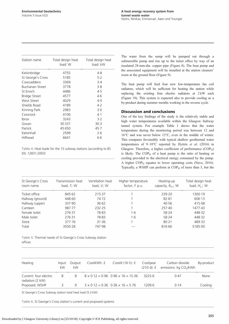
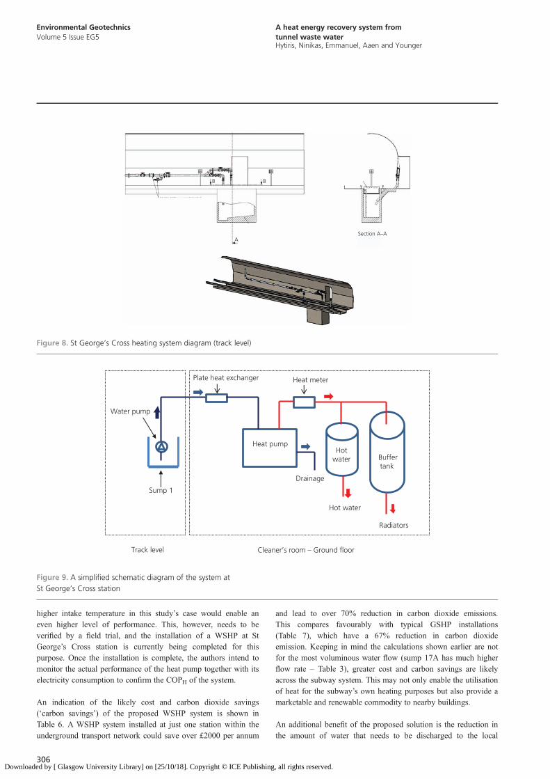
The water from the sump will be pumped out through asubmersible pump and rise up to the ticket office by way of aninsulated 28-mm-dia. copper pipe (Figure 8). The heat pump andthe associated equipment will be installed at the station cleaners’room at the ground floor (Figure 9).
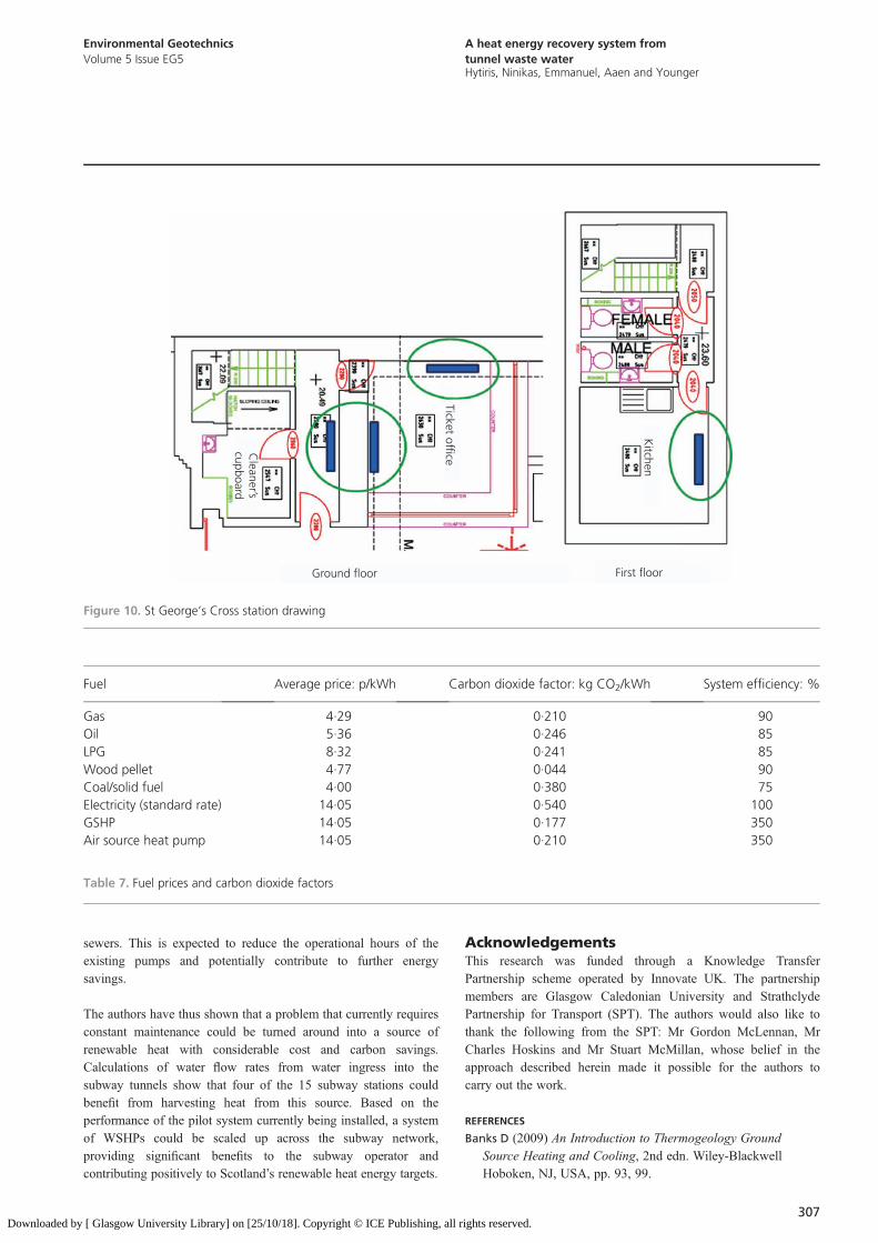
The heat pump will feed four new low-temperature fan coilradiators, which will be sufficient for heating the station whilereplacing the existing four electric radiators at 2 kW each(Figure 10). This system is expected also to provide cooling as aby-product during summer months working in the reverse cycle.
Discussion and conclusionsOne of the key findings of the study is the relatively stable andhigh water temperatures available within the Glasgow Subwaytunnel system. For example Table 1 shows that the watertemperature during the monitoring period was between 12 and16°C and was never below 12°C, even in the middle of winter.This compares favourably with typical shallow geothermal watertemperatures of 9–10°C reported by Hytiris et al. (2016) inGlasgow. Therefore, a higher coefficient of performance (COPH)is likely. The COPH of a heat pump is the ratio of heating orcooling provided to the electrical energy consumed by the pump.A higher COPH equates to lower operating costs (Nave, 2016).Typically, a WSHP can perform at COPH of more than 3, but the
St George’s Crossroom name
Transmission heatload, Ti: W
Ventilation heatload, Vi: W
Higher temperaturefactor, f: p.u.
ights reserved.
Heating-upcapacity, RH,i: W
Total design heatload, HL,i: W
Ticket office
845·62 215·37 1 239·20 1300·19 Hallway (ground) 448·60 74·72 1 82·81 606·13 Hallway (upper) 337·90 36·62 1 40·56 415·08 Canteen 987·77 232·25 1 257·40 1477·43 Female toilet 276·31 78·83 1·6 58·24 448·32 Male toilet 276·31 78·83 1·6 58·24 448·32 Store 377·76 31·36 1 80·21 489·33 Total 3550·28 747·98 — 816·66 5185·00Table 5. Thermal needs of St George’s Cross Subway stationoffices
Heating
Input:kWOutput:kW
Cost/kWh: £
Cost/d (16 h): £ Cost/year(210 d): £Carbon dioxideemissions: kg CO2/kWh
By-product
Current: four electricradiators (2 kW)
8
8 8 × 0·12 = 0·96 0·96 × 16 = 15·36 3225·6 0·47 NoneProposed: WSHP
3 9 3 × 0·12 = 0·36 0·36 × 16 = 5·76 1209·6 0·14 CoolingSt George’s Cross Subway station total heat load (5·2 kW)
Table 6. St George’s Cross station’s current and proposed systems
Station name
Total design heatload: WTotal design heatload: kW
Kelvinbridge
4755 4·8 St George’s Cross 5185 5·2 Cowcaddens 3369 3·4 Buchanan Street 3778 3·8 St Enoch 4486 4·5 Bridge Street 4577 4·6 West Street 4029 4·0 Shields Road 4189 4·2 Kinning Park 2983 3·0 Cessnock 4106 4·1 Ibrox 3243 3·2 Govan 30 331 30·3 Partick 45 650 45·7 Kelvinhall 2599 2·6 Hillhead 6641 6·6Table 4. Heat loads for the 15 subway stations (according to BSEN: 12831:2003)
305
Environmental GeotechnicsVolume 5 Issue EG5
A heat energy recovery system fromtunnel waste waterHytiris, Ninikas, Emmanuel, Aaen and Younger
Download
higher intake temperature in this study’s case would enable aneven higher level of performance. This, however, needs to beverified by a field trial, and the installation of a WSHP at StGeorge’s Cross station is currently being completed for thispurpose. Once the installation is complete, the authors intend tomonitor the actual performance of the heat pump together with itselectricity consumption to confirm the COPH of the system.
An indication of the likely cost and carbon dioxide savings(‘carbon savings’) of the proposed WSHP system is shown inTable 6. A WSHP system installed at just one station within theunderground transport network could save over £2000 per annum
306ed by [ Glasgow University Library] on [25/10/18]. Copyright © ICE Publishing
and lead to over 70% reduction in carbon dioxide emissions.This compares favourably with typical GSHP installations(Table 7), which have a 67% reduction in carbon dioxideemission. Keeping in mind the calculations shown earlier are notfor the most voluminous water flow (sump 17A has much higherflow rate – Table 3), greater cost and carbon savings are likelyacross the subway system. This may not only enable the utilisationof heat for the subway’s own heating purposes but also provide amarketable and renewable commodity to nearby buildings.
An additional benefit of the proposed solution is the reduction inthe amount of water that needs to be discharged to the local
B B
Section A–AA
Figure 8. St George’s Cross heating system diagram (track level)
Heat pump
Buffertank
Hotwater
Sump 1
Plate heat exchanger
Water pump
Heat meter
Drainage
Hot water
Radiators
Track level Cleaner’s room – Ground floor
Figure 9. A simplified schematic diagram of the system atSt George’s Cross station
, all rights reserved.
Environmental GeotechnicsVolume 5 Issue EG5
A heat energy recovery system fromtunnel waste waterHytiris, Ninikas, Emmanuel, Aaen and Younger
Downloaded by
sewers. This is expected to reduce the operational hours of theexisting pumps and potentially contribute to further energysavings.
The authors have thus shown that a problem that currently requiresconstant maintenance could be turned around into a source ofrenewable heat with considerable cost and carbon savings.Calculations of water flow rates from water ingress into thesubway tunnels show that four of the 15 subway stations couldbenefit from harvesting heat from this source. Based on theperformance of the pilot system currently being installed, a systemof WSHPs could be scaled up across the subway network,providing significant benefits to the subway operator andcontributing positively to Scotland’s renewable heat energy targets.
[ Glasgow University Library] on [25/10/18]. Copyright © ICE Publishing, all r
AcknowledgementsThis research was funded through a Knowledge TransferPartnership scheme operated by Innovate UK. The partnershipmembers are Glasgow Caledonian University and StrathclydePartnership for Transport (SPT). The authors would also like tothank the following from the SPT: Mr Gordon McLennan, MrCharles Hoskins and Mr Stuart McMillan, whose belief in theapproach described herein made it possible for the authors tocarry out the work.
REFERENCES
Banks D (2009) An Introduction to Thermogeology GroundSource Heating and Cooling, 2nd edn. Wiley-BlackwellHoboken, NJ, USA, pp. 93, 99.
Ground floor First floor
Cleaner’s
cupboard
Ticket office
Kitchen
Figure 10. St George’s Cross station drawing
Fuel
Average price: p/kWh Carbon dioxide factor: kg CO2/kWhights reserved.
System efficiency: %
Gas
4·29 0·210 90 Oil 5·36 0·246 85 LPG 8·32 0·241 85 Wood pellet 4·77 0·044 90 Coal/solid fuel 4·00 0·380 75 Electricity (standard rate) 14·05 0·540 100 GSHP 14·05 0·177 350 Air source heat pump 14·05 0·210 350Table 7. Fuel prices and carbon dioxide factors
307

Environmental GeotechnicsVolume 5 Issue EG5
A heat energy recovery system fromtunnel waste waterHytiris, Ninikas, Emmanuel, Aaen and Younger
Download
BKV Zrt (2011) Annual Report 2011. BKV Zrt, Budapest,Hungary. See http://static.bkv.hu/ftp/ftp/annual_report/annualreport2011en.pdf (accessed 12/04/2016).
Branz (Building Research Association of New Zealand) (2015)Heat Pumps. Branz, Wellington, New Zealand. See: http://www.level.org.nz/energy/space-heating/heat-pumps/ (accessed 10/04/2016).
BSI (2003) BS EN 12831:2003: Heating systems in buildings.Method for calculation of the design heat load. BSI, London, UK.
Climate Change Act 2008 (2008) Elizabeth II. Chapter 27. HerMajesty’s Stationery Office, London, UK. See http://www.legislation.gov.uk/ukpga/2008/27/contents (accessed 14/04/2016).
Ground Source Heat Pump Association (2015) What Is GroundSource Energy? Ground Source Heat Pump Association. Seehttp://www.gshp.org.uk/gshp.htm (accessed 14/04/2016).
Hytiris N, Emmanuel R, Aaen B et al. (2016) Heat recoveryfrom mineworkings: opportunities in the Glasgow area.
308ed by [ Glasgow University Library] on [25/10/18]. Copyright © ICE Publishing
Environmental Geotechnics, http://dx.doi.org/10.1680/envgeo.15.00007.
NRC (Natural Resources Canada) (2015) What Is a Heat Pumpand How Does It Work? NRC. Ottawa, ON, Canada. Seehttp://www.nrcan.gc.ca/energy/publications/efficiency/heating-heat-pump/6827 (accessed 14/04/2016).
Nave CR (2016) HyperPhysics: Coefficient of Performance.Georgia State University, Atlanta, GA, USA. See http://hyperphysics.phy-astr.gsu.edu/hbase/thermo/heatpump.html#c3(accessed 14/04/2016).
Scottish Government (2012) Scotland Beats 2011 Green EnergyTarget. Scottish Government, Edinburgh, UK. Seehttp://www.scotland.gov.uk/News/Releases/2012/03/geenenergytargets29032012 (accessed 14/04/2016).
US DOE (US Department of Energy) (2015) Geothermal HeatPumps. US DOE, Washington, DC, USA. See http://energy.gov/energysaver/geothermal-heat-pumps (accessed09/04/2016).
How can you contribute?
To discuss this paper, please submit up to 500 words tothe editor at [email protected]. Your contribution will beforwarded to the author(s) for a reply and, if consideredappropriate by the editorial board, it will be published as adiscussion in a future issue of the journal.
, all rights reserved.


![Waste Heat Recovery[1]](https://static.fdocuments.net/doc/165x107/577d28de1a28ab4e1ea56f01/waste-heat-recovery1.jpg)