A Guide to TracVision SA - RV Tech Library
59
KVH Industries, Inc. A Guide to TracVision SA • Installation Instructions • User’s Guide • Technical Manual
Transcript of A Guide to TracVision SA - RV Tech Library

KVH Industries, Inc.A Guide to TracVision SA• Installation Instructions• User’s Guide• Technical Manual

Congratulations!You have selected one of the most advanced land-mobile satellitetracking systems available today. KVH® Industries’ TracVision® SAis designed for use with DIRECTV® and the DISH™ Network.This manual provides detailed instructions on the properinstallation, use, and maintenance of your TracVision SA system.
Throughout this manual, important information is marked foryour attention by these icons:
Direct questions, comments, or suggestions to:
KVH Industries, Inc.50 Enterprise CenterMiddletown, RI 02842 USAtel: +1 401 847-3327fax: +1 401 849-0045e-mail: [email protected]: http://www.kvh.com
A helpful tip that either directs you to a related area within the manual or offers suggestions on getting the highest quality out of your system.
An alert to important information regarding procedures, product specifications, or product use.
An electrical safety warning to help identify electrical issues that can be a hazard to either this KVH product or a user.
Information about installation, maintenance, troubleshooting, or other mechanical issues.
TracVision SA Serial Number
This serial number will be requiredfor all troubleshooting or servicecalls made regarding this product.
KVH Part # 54-0149 B
© 2000, KVH Industries, Inc.

TracVision® and KVH® are registered trademarks of KVH Industries, Inc.
DIRECTV® is an official trademark of DIRECTV, a unit of GM Hughes Electronics Corporation.
DISH™ Network is an official trademark of EchoStar Communications Corporation.

Table of Contents1 Introduction . . . . . . . . . . . . . . . . . . . . . . . . . . . . . . .1-11.1 Digital Satellite Television . . . . . . . . . . . . . . . . . . . . . . . . . . . . . .1-1
1.2 TracVision SA System Overview . . . . . . . . . . . . . . . . . . . . . . . .1-1
1.2.1 TracVision SA Components....................................................1-2
1.2.2 Integrated Receiver Decoder..................................................1-2
1.3 Materials Provided with TracVision SA . . . . . . . . . . . . . . . . . . . .1-3
1.3.1 Additional Materials Required for TracVision SA Use ............1-3
2 Installation . . . . . . . . . . . . . . . . . . . . . . . . . . . . . . . .2-12.1 Overview of Installation . . . . . . . . . . . . . . . . . . . . . . . . . . . . . . .2-1
2.1.1 Installation Tools and Materials Required...............................2-1
2.1.2 Kitpack....................................................................................2-2
2.2 Choosing the Best Location . . . . . . . . . . . . . . . . . . . . . . . . . . . .2-2
2.3 Mounting the Antenna Unit . . . . . . . . . . . . . . . . . . . . . . . . . . . . .2-2
2.4 Connecting the Antenna Unit . . . . . . . . . . . . . . . . . . . . . . . . . . .2-6
2.4.1 Connecting the Antenna Data Cable to the IRD ....................2-8
2.4.2 Connecting the Antenna to Vehicle Power ...........................2-10
2.4.3 Connecting the Antenna RF Signal Cable to the IRD ..........2-11
2.5 Checking Out the System . . . . . . . . . . . . . . . . . . . . . . . . . . . . .2-13
2.6 Completing the Installation Process . . . . . . . . . . . . . . . . . . . .2-14
2.7 Configuring TracVision SA for Remote Satellite Dish Operation . . . . . . . . . . . . . . . . . . . . . . . . . . . . . .2-14
3 Operation . . . . . . . . . . . . . . . . . . . . . . . . . . . . . . . . .3-1
4 Troubleshooting . . . . . . . . . . . . . . . . . . . . . . . . . . . . .4-14.1 Causes and Remedies for Common Operational Issues . . . . . .4-1
4.1.1 Blown Fuse or No Power........................................................4-2
4.1.2 Satellite Signal Blocked..........................................................4-2
4.1.3 Outside Satellite Coverage Zone ...........................................4-2
4.1.4 Incorrect or Loose RF Connectors .........................................4-2
i54-0149 Rev. B

4.2 IRD Troubleshooting . . . . . . . . . . . . . . . . . . . . . . . . . . . . . . . . . .4-3
4.2.1 IRD Data Port or Cable/Wiring ...............................................4-3
4.2.2 AC Power Fluctuating.............................................................4-3
4.2.3 EchoStar IRD Commissioning Check.....................................4-3
4.2.4 Failed IRD Status Check ........................................................4-3
4.2.5 IRD Faulty...............................................................................4-4
4.3 LNB Faults . . . . . . . . . . . . . . . . . . . . . . . . . . . . . . . . . . . . . . . . . .4-4
4.4 Computer Diagnostics . . . . . . . . . . . . . . . . . . . . . . . . . . . . . . . .4-5
4.5 Maintenance Port Parser Commands . . . . . . . . . . . . . . . . . . . . .4-5
5 Maintenance . . . . . . . . . . . . . . . . . . . . . . . . . . . . . . .5-15.1 Warranty/Service Information . . . . . . . . . . . . . . . . . . . . . . . . . . .5-1
5.2 Preventive Maintenance . . . . . . . . . . . . . . . . . . . . . . . . . . . . . . .5-1
5.3 Replaceable Parts . . . . . . . . . . . . . . . . . . . . . . . . . . . . . . . . . . . .5-2
5.4 Field Replaceable Unit Procedures . . . . . . . . . . . . . . . . . . . . . .5-3
5.4.1 PCB Removal and Replacement............................................5-5
5.4.2 RF Detector ............................................................................5-6
5.4.3 Antenna LNB Replacement ....................................................5-6
5.4.4 EchoStar Adapter Replacement .............................................5-8
5.5 Preparation for Shipment . . . . . . . . . . . . . . . . . . . . . . . . . . . . . .5-8
Appendix A System Specifications . . . . . . . . . . . . . . . . . .A-1
Appendix B Functional Block Diagram . . . . . . . . . . . . . . . .B-1
Appendix C Data Cable Wiring . . . . . . . . . . . . . . . . . . . . .C-1C.1 Wiring TracVision SA to a 15-pin Data Connector . . . . . . . . . . .C-1
C.2 DB9 Data Connector Pin Assignments . . . . . . . . . . . . . . . . . . .C-2
Appendix D EchoStar IRD Commissioning Procedure . . . . . .D-1
Appendix E Startup Data Sequence . . . . . . . . . . . . . . . . . .E-1
ii

Appendix F Maintenance Port Parser Commands . . . . . . . . .F-1F.1 System Commands . . . . . . . . . . . . . . . . . . . . . . . . . . . . . . . . . . .F-1
F.2 Manual Positioning Commands . . . . . . . . . . . . . . . . . . . . . . . . .F-2
F.3 Operational Commands . . . . . . . . . . . . . . . . . . . . . . . . . . . . . . .F-3
F.4 Target and Signal Commands . . . . . . . . . . . . . . . . . . . . . . . . . .F-4
List of FiguresFigure 1-1 TracVision SA System Configuration . . . . . . . . . . . . . . . . .1-1
Figure 1-2 Primary Components of the TracVision SA . . . . . . . . . . . .1-2
Figure 2-1 Proper Orientation of the Antenna Unit . . . . . . . . . . . . . . .2-3
Figure 2-2 Forward Shipping Restraint (Arranged for Shipping) . . . . .2-3
Figure 2-3 TracVision SA Shipping Restraints (Top View) . . . . . . . . .2-3
Figure 2-4 Mounting the Unit on a Curved Surface . . . . . . . . . . . . . .2-4
Figure 2-5 Baseplate Dimensions . . . . . . . . . . . . . . . . . . . . . . . . . . .2-4
Figure 2-6a Connectors Facing Rear of Vehicle – Factory-drilled Drain Hole Locations . . . . . . . . . . . . . . . . .2-5
Figure 2-6b Connectors Facing Front of Vehicle – Recommended Drain Hole Locations . . . . . . . . . . . . . . . .2-5
Figure 2-7 Forward Shipping Restraint Storage . . . . . . . . . . . . . . . . .2-6
Figure 2-8 Proper Wire-to-Terminal Connection . . . . . . . . . . . . . . . . .2-6
Figure 2-9 Moving the Antenna Reflector . . . . . . . . . . . . . . . . . . . . . .2-7
Figure 2-10 Cable Port Assignments (Exterior of Baseplate) . . . . . . . .2-7
Figure 2-11 Cable Overlap within the TracVision SA Baseplate . . . . . .2-7
Figure 2-12 Proper Terminal Strip Wiring Arrangement – Data Cable . . . . . . . . . . . . . . . . . . . . . . . . . . . . . . . . . . . .2-8
Figure 2-13 DB9 Connector . . . . . . . . . . . . . . . . . . . . . . . . . . . . . . . .2-8
Figure 2-14 EchoStar Adapter Installation . . . . . . . . . . . . . . . . . . . . . .2-9
Figure 2-15 Proper Wire-to-Terminal Connection . . . . . . . . . . . . . . . .2-10
Figure 2-16 Proper Terminal Strip Wiring Arrangement – Power Cable . . . . . . . . . . . . . . . . . . . . . . . . . . . . . . . . .2-10
Figure 2-17 Wiring TracVision SA to Vehicle Power . . . . . . . . . . . . . .2-11
Figure 2-18 Connecting the RF Cable to TracVision SA . . . . . . . . . . .2-11
iii54-0149 Rev. B

Figure 2-19a-d Attaching the KVH-provided F-connector to an RF Cable . . . . . . . . . . . . . . . . . . . . . . . . . . . . . . . .2-12
Figure 2-20 Remote Dish Wiring Configuration . . . . . . . . . . . . . . . . .2-14
Figure 5-1 Antenna, PCB, and Rotating Plate . . . . . . . . . . . . . . . . . .5-3
Figure 5-2 Close-up of Linear Actuator, Pivot Bracket, and Pin . . . . .5-3
Figure 5-3 Antenna Assembly . . . . . . . . . . . . . . . . . . . . . . . . . . . . . .5-4
Figure 5-4 Close-up of RF Detector, PCB, and Cover . . . . . . . . . . . .5-4
Figure 5-5 PCB Connector Locations – Rear View (not to scale) . . . .5-5
Figure 5-6 Attaching the Shipping Restraints to the Antenna Baseplate . . . . . . . . . . . . . . . . . . . . . . . . . . . . . .5-9
Figure 5-7 Securing the Forward Shipping Restraint . . . . . . . . . . . . .5-9
Figure C-1 DB9 Male and Female Connector Arrangement . . . . . . . .C-2
List of TablesTable 1-1 TracVision SA Packing List . . . . . . . . . . . . . . . . . . . . . .1-3
Table 2-1 Kitpack Contents . . . . . . . . . . . . . . . . . . . . . . . . . . . . . .2-2
Table 2-3 DSS On-screen Messages . . . . . . . . . . . . . . . . . . . . .2-13
Table 2-2 TracVision SA Operational Messages . . . . . . . . . . . . .2-13
Table 3-1 TracVision SA Automated Procedures . . . . . . . . . . . . . .3-1
Table 4-1 Troubleshooting Matrix . . . . . . . . . . . . . . . . . . . . . . . . .4-1
Table 5-1 Field Replaceable Units . . . . . . . . . . . . . . . . . . . . . . . .5-2
Table A-1 TracVision SA System Specifications . . . . . . . . . . . . . .A-1
Table C-1 Alternate Wiring Arrangement for TracVision SAData Cable to DB15 (15-wire) Connector . . . . . . . . . . .C-1
Table C-2 DB9 Pin Functions and Color Code . . . . . . . . . . . . . . .C-2
Table F-1 System Commands . . . . . . . . . . . . . . . . . . . . . . . . . . . .F-1
Table F-2 Manual Positioning Commands . . . . . . . . . . . . . . . . . . .F-2
Table F-3 Operational Commands . . . . . . . . . . . . . . . . . . . . . . . .F-3
Table F-4 Target and Signal Commands . . . . . . . . . . . . . . . . . . . .F-4
iv

1 Introduction1.1 Digital Satellite TelevisionThe DIRECTV® and DISH™ Network systems transmit digitalaudio and video data from land-based transmitters to a satellite“parked” above the equator. Each satellite relays the signals inspot beams covering the continental United States andcontiguous waters. TracVision SA automatically identifies, lockson to and receives signals from the appropriate satellite whenyour vehicle is stationary.
1.2 TracVision SA System OverviewA complete satellite TV system includes the TracVision SAconnected to an Integrated Receiver Decoder (IRD), aka a“satellite receiver,” and a television set. A desktop or laptopcomputer is used to conduct diagnostics. The interrelationship ofunits is illustrated in Figure 1-1. System specifications and afunctional block diagram are provided in Appendices A and B,respectively.
1-1
Introduction
54-0149 Rev. B
Low-speedData Port
11-16 Volts DC
2.5-3.5 Amps
Satellite Receiver
9-Pin PC
Communications
PortCo-axial�Cable
Options Purchased Separately
Television
Figure 1-1TracVision SA SystemConfiguration
TracVision SA is equipped with asingle-port Low Noise Block (LNB)that can provide signals to a singleIRD. Should you wish to equip yourvehicle with multiple TVs and IRDs,a dual-port LNB is available as anoption (KVH Part Number 19-0056).
TracVision SA is a self-acquiringsatellite TV antenna for use whenyour vehicle is stationary. Thesystem is not designed to track theTV satellite when the vehicle ismoving.

1.2.1 TracVision SA ComponentsThe Antenna Unit includes the antenna positioning mechanism,signal front end, power supply and control elements. Theseinclude antenna drive controls and mechanisms, the cable wrapsubassembly, power conditioning and regulating circuits, and theRF detector. The antenna is a parabolic dish mounting a single-port low noise block (LNB) converter with built-in preamplifier.A molded ABS radome encloses the baseplate and is secured inplace with standard fasteners. Liquid-tight (watertight) fittingslocated on the back of the baseplate join the power, signal, andcontrol cabling from below-decks units.
1.2.2 Integrated Receiver DecoderThe IRD receives satellite signals from the Antenna Unit forsignal decoding, processing and channel selection, and sends thesignals to the TV set for viewing. Messages are sent from the IRDto the Antenna Unit and messages are received from the AntennaUnit for display on the television screen. The IRD also providesthe interface for the user to activate authorization for reception.Please refer to the User’s Manual provided with your selectedIRD for complete operating instructions.
1-2
A Guide to TracVision SA
Figure 1-2Primary Components of the
TracVision SA
On-screen messages are notavailable with a DISH Network IRD.
Radome
Antenna Unit
Mounting Plate
Antenna
Reflector
LNB
Always lift the antenna unit by thegray baseplate and not the radome,antenna reflector, or internalmechanical assemblies. NEVERpick up the unit by the LNB!

1.3 Materials Provided withTracVision SA
Table 1-1 lists the units, cables, and materials packed in theTracVision SA package by name and KVH part number.
Component KVH Part No.
Antenna Unit (comprising): 01-0225-02
Baseplate Assembly 02-0952-02
Radome Assembly 02-0953-02
RF Cable (30') 32-0589-30
Power Cable (30') 32-0590-30
Data Cable (30') 32-0591-30
Mounting Plate 20-0668
Kitpack* 72-0094
Installation and Operation Manual 54-0149
* A complete listing of kitpack contents is provided in Section 2.1.2, “Kitpack.”
1.3.1 Additional Materials Required forTracVision SA Use
To make full use of your new TracVision SA and receive satelliteTV on the road, you will need to provide/purchase thefollowing:
• Television
• Appropriate IRD for your selected satellite TV service (if using the DISH Network, a Model 4000 or 5000 IRD will be required)
• Sealing materials to weatherproof cable holes andseal mounting plate
• Optional KVH EchoStar Adapter (for use with theDISH Network service and IRD)
1-3
Introduction
54-0149 Rev. B
Operation of the DISH Networkrequires the purchase of anEchoStar IRD Adapter. To purchasean EchoStar Adapter, contact KVHor your local KVH dealer and askfor KVH Part Number 02-0899.
Table 1-1TracVision SA Packing List
Cables for the TracVision SA arestored beneath the antenna unitduring shipping.


2-1
Installation
54-0149 Rev. B
2 Installation2.1 Overview of InstallationTracVision SA is designed for simple installation and setup. Justfollow these easy steps:
1. Choose the antenna location.
2. Mount the antenna unit.
3. Connect the antenna unit cables.
4. Connect the antenna unit to the TV IRD.
5. Connect the TV IRD to the TV.
2.1.1 Installation Tools and Materials Required• Electric drill
• 3⁄16”-drill bit and 1⁄2” hole saw
• 1⁄2”-socket wrench
• #2 Phillips and #0 flat tip screwdrivers
• Augat Snap ‘n Seal Crimp/Strip Tool (PartNumber IT1000) if using the KVH-provided F-connector
• Silicone sealant or RTV
• Thread locker (as required)
• 7⁄16”-open end wrench
• Wire strippers
• Adhesive suitable for specific roof constructionand materials (e.g., butyl rubber adhesive tape orother liquid adhesive)
• Rivet Gun and 3⁄16”-rivets (or other fastener suitablefor specific roof construction)
• Terminal crimp tool
• Optional PC with terminal emulation softwaresuch as PROCOMM, Windows Terminal, orWindows 95 Hyperterminal
Plan the entire installation beforeproceeding! Take into accountcomponent placement, runningcable distances between units, andaccessibility to the equipment afterinstallation.
The product serial number may befound in front of the antennareflector on the rotating plate aswell as on the inside front cover ofthis manual.
While some DIRECTV IRDs offer on-screen messages, it isrecommended that a PC beavailable for all installations of both DIRECTV and EchoStar.

2-2
A Guide to TracVision SA
2.1.2 KitpackTable 2-1 lists the materials provided in the TracVision SAkitpack.
Part Qty. KVH Part No.
Rocker Switch 1 12-0048
Switch Plate 1 19-0167
RF F-Connector 2 23-0170
Terminal Crimp (female) 5 23-0188-03
1⁄4˝-20 x 5⁄8˝ hex screws 4 14-0250-0010
1⁄4˝ flat washers 4 14-0251
Tie-wraps 5 22-0013
Flash kit cable and adapter 1 02-1029
2.2 Choosing the Best Location• The ideal antenna site has a clear view of the
horizon/satellite all around.
• Keep the antenna clear of any obstructions on theroof (e.g., air conditioners).
• Consider the location of the antenna relative to thelocation of any equipment or necessary wiringwithin the vehicle.
• For best operation, mount the antenna on ahorizontal surface.
2.3 Mounting the Antenna Unit1. Remove antenna unit from shipping container.
2. Remove and save the 8 pan head screws andsealing washers that hold radome to baseplate.Carefully lift radome straight up until clear ofantenna assembly and set aside.
3. Position antenna unit in desired location on thecenterline of the vehicle with baseplate andmounting plate arrows facing in the samedirection (either forward or backward). The properorientation is illustrated in Figure 2-1 on thefollowing page.
Table 2-1Kitpack Contents
Always lift the antenna unit by thegray baseplate, never by theradome or any portion of theantenna assembly!
The liquid-tight connectors onTracVision SA may face eitherforward or backward along thecenterline of the vehicle for moreconvenient installation.

2-3
Installation
54-0149 Rev. B
4. While the baseplate is in place, mark location(s) onroof for cable access to permit convenient cableaccess to the liquid-tight fittings on the back of thebaseplate.
5. Cut tie-wraps holding antenna unit to the forwardshipping restraint.
6. Remove additional nuts and washers connectingbaseplate and shipping restraints to the mountingplate. The positions of all three shipping restraintsare pictured in Figure 2-3.
Figure 2-1Proper Orientation of the Antenna Unit
Vehicle
Cen
terline
Figure 2-2Forward Shipping Restraint(Arranged for Shipping)
2 tie-wraps used
to secure LNB arm
Forward Shipping Restraint
Forward Shipping Restraint
Nuts and Washers
Do not discard the shippingrestraints, washers, or the nuts.Save them for future use in casethe antenna unit needs to beremoved and shipped to anotherlocation. Four 1⁄4˝-20 x 5⁄8˝ hex headscrews have been provided in thekitpack for shipping as the boltsused to hold the shipping restraintduring initial shipping are integralparts of the mounting plate.
Rotating Plate�
Shipping Restraint
Rotating Plate�
Shipping Restraint
Forward Shipping �
Restraint for �
LNB Bracket
Figure 2-3TracVision SA Shipping Restraints(Top View)

2-4
A Guide to TracVision SA
7. Remove antenna unit from mounting plate.
8. The mounting plate allows the antenna unit to bemounted on a curved roof. While the perimeter ofthe mounting plate is secured to the vehicle withthe appropriate fasteners, two flexible wings allowthe rear mounting bolts to attach to the antennabaseplate. These may be angled upward to ensurea secure mounting, as shown in Figure 2-4.
9. Using the mounting plate as a template, drilltwenty-three 3⁄16”-holes through roof of vehicle.Remove plate and clean roof surface. Thedimensions of the baseplate are shown in Figure 2-5.
Figure 2-4Mounting the Unit on a
Curved Surface
Antenna Baseplate bolts to this “wing,”which can remain horizontal.
MountingPlate Wing
Mounting Plate can be tightened down to conform to a curved surface.
24.0"
28.8"
Figure 2-5Baseplate Dimensions
2-5
Installation
54-0149 Rev. B
10. Place a strip of black butyl rubber adhesive or an equivalent over all holes. If using a liquidconstruction adhesive, apply bead to mountingplate in a zig-zag pattern.
11. Reposition mounting plate over tape/adhesiveand attach using 3⁄16”-diameter rivets (orappropriate fasteners). Seal all rivet heads andedges with silicone.
12. Drill cable access hole(s) in vehicle.
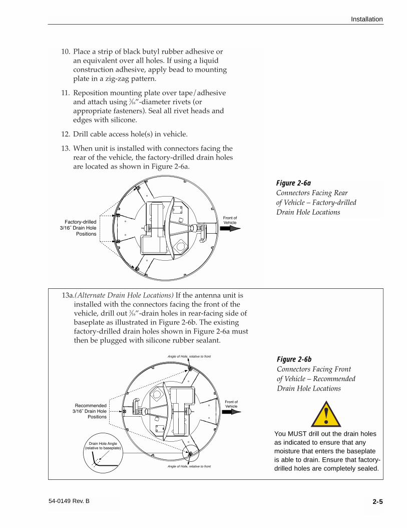
13. When unit is installed with connectors facing therear of the vehicle, the factory-drilled drain holesare located as shown in Figure 2-6a.
Figure 2-6aConnectors Facing Rear of Vehicle – Factory-drilledDrain Hole Locations
Factory-drilled
3/16ý Drain Hole
Positions
Front of
Vehicle
Recommended
3/16ý Drain Hole
Positions
Drain Hole Angle
(relative to baseplate)
Front of
Vehicle
Angle of Hole, relative to front
Angle of Hole, relative to front
Figure 2-6bConnectors Facing Front of Vehicle – Recommended Drain Hole Locations
You MUST drill out the drain holesas indicated to ensure that anymoisture that enters the baseplateis able to drain. Ensure that factory-drilled holes are completely sealed.
13a.(Alternate Drain Hole Locations) If the antenna unit isinstalled with the connectors facing the front of thevehicle, drill out 3⁄16”-drain holes in rear-facing side ofbaseplate as illustrated in Figure 2-6b. The existingfactory-drilled drain holes shown in Figure 2-6a mustthen be plugged with silicone rubber sealant.

2-6
A Guide to TracVision SA
14. Place antenna unit on mounting plate and secureusing nuts and washers removed in Step 2.
15. For convenient storage, the forward shippingrestraint may be rotated 180˚ and secured to itsorginal mounting bolts as pictured in Figure 2-7.
16. Proceed to Section 2.4, “Connecting the AntennaUnit,” to wire the TracVision SA system. Theradome will be placed back on the baseplate usingthe hardware removed in Step 2 after wiring andinitializing the system.
2.4 Connecting the Antenna UnitThe following sections provide instructions for properly wiringthe Antenna Unit to the IRD and to vehicle power.
Tips for Safe and Successful Wiring within the TracVision SA Baseplate
• When attaching cables to the TracVision SAterminal connector strips, make sure the insulationis stripped back approximately 1⁄4˝. Twist the wiresgently to help achieve a good connection. Do notpinch insulation inside the connector.
• After attaching the power and data cables to theappropriate terminal connector strips, tug gentlyto ensure a firm connection.
• After attaching cables within the TracVision SAbaseplate, eliminate any unnecessary slack in thecables before tightening the liquid-tight fittings.
Figure 2-8Proper Wire-to-Terminal
Connection
Insulation
Terminal Connector
1/4˝
DO NOT leave an extra length ofcable within the baseplate as aservice loop. All service loopsshould be stored within thevehicle’s cable access.
Forward Shipping Restraint
Installation Nuts and Washers
LNBFigure 2-7
Forward Shipping Restraint Storage
DO NOT store the rotating plateshipping restraints inside theTracVision SA baseplate.

2-7
Installation
54-0149 Rev. B
• Run the RF signal cable into the baseplate last. Itwill help keep the power and data cables clear ofthe antenna and LNB.
• After hooking up all of the wiring and removing anyslack, slowly rotate, raise, and lower the antennareflector to make certain that the cables are all clearof any moving elements.
• Check to be certain that the elevation axis actuatormotor shaft (pictured in Section 5, Maintenance,Figure 5-2) clears all cable connections.
• Completely seal all rooftop cable access holes.
TracVision SA Cable Ports
On one side of the baseplate are four liquid-tight fittings, whichserve the dual purpose of relieving strain on the cables as well asproviding a tight seal around the cable access ports.
When wiring is done properly, the sets of cables will overlap eachother, as illustrated in Figure 2-11.
Figure 2-10Cable Port Assignments (Exterior of Baseplate)
Not�Used
Power(#4)
RF(#2)
Data(#3)
Figure 2-9Moving the Antenna Reflector
Data
Power
RF Cable Figure 2-11Cable Overlap within theTracVision SA Baseplate

2-8
A Guide to TracVision SA
2.4.1 Connecting the Antenna Data Cable to the IRD
TracVision SA will not function properly unless you connect thedata cable, the procedures for which vary based on your selectedsatellite TV service. The end of the data cable fitted with two DB9connectors remains within the vehicle. This will be hooked up tothe IRD as discussed later. For your reference, the pinassignments for the data cable DB9 connectors are detailed inAppendix C. The other end of the data cable will be attached tothe TracVision SA as described in the following section.
TracVision SA Data Cable Wiring Process1. Feed the cable up to the roof and through the third
liquid-tight fitting (#3) from the left as pictured inFigure 2-10.
2. Refer to Figure 2-12 for the proper arrangement ofdata cable wires within the terminal strip.
3. After connecting the data cable to the TracVision SA, hook up the other end to the IRDas described in the next subsections.
DIRECTV
The data cable for TracVision SA is equipped with a male DB9 (low-speed data port) connector. Connect the DB9 connectoron the data cable to the low-speed data port on the back of theIRD.
Wiring to an IRD with a DB15 Connector
Should the IRD only be equipped with a DB15 connector, contactKVH for an adapter or follow the alternate wiring directionsprovided in Appendix C.
Figure 2-13DB9 Connector
Shield
Red
Black
Brown/White
Orange/White
White/Orange
Green/White
White/Blue
Blue/White
Shield
Grnd
+12v DC
Grnd
RTN
PC_RXD
PC_TXD
RTN
IRD_RXD
IRD_TXD
Grnd
1
2
3
4
5
6
7
8
9
10
Figure 2-12Proper Terminal Strip Wiring
Arrangement – Data Cable
All IRDs are susceptible to ACpower fluctuations that can result inthe IRD locking up and requiring areset. Refer to Section 4.2, “IRDTroubleshooting,” for a solution tothis issue.

2-9
Installation
54-0149 Rev. B
DISH Network
Unlike the DIRECTV IRDs, the EchoStar IRD used with the DISH Network is not equipped with a DB9 connector. As a result, you will need to purchase an EchoStar Adapter (KVH Part Number 02-0899).
The rear of the DISH Network IRD has a port labeled “HighSpeed Data Port.”
1. Remove the protective metal plate to expose theHigh Speed Data Port. (Save the screws and platein the IRD packing material in case the unit mustbe returned for repairs.)
2. Install the KVH EchoStar Adapter as shown inFigure 2-14. Secure the Adapter to the IRD usingthe captive screws in the Adapter.
3. Connect the DB9 connector on the data cable tothe EchoStar Adapter DB9.
Commissioning the IRD
Please refer to the user manual that accompanied your IRD forinstructions on properly commissioning the system.
EchoStar Commissioning Issues
EchoStar IRDs that have not been commissioned within severalmonths of manufacture require additional steps to complete theprocess. Refer to Appendix D for complete details.
Figure 2-14EchoStar Adapter Installation
High Speed Data Port
ECHOSTAR®
Adapter
This port is static-sensitive, soobserve the proper precautions.Before starting, make certain thatthe IRD is not plugged into an AC outlet.

2-10
A Guide to TracVision SA
2.4.2 Connecting the Antenna to Vehicle Power
Tips for Safe and Successful Wiring within the TracVision SA Baseplate
• When attaching cables to the TracVision SAterminal connector strips, make sure the insulationis stripped back approximately 1⁄4˝. Twist the wiresgently to help achieve a good connection. Do notpinch insulation inside the connector.
• After attaching the power and data cables to theappropriate terminal connector strips, tug gentlyto ensure a firm connection.
• After attaching cables within the TracVision SAbaseplate, eliminate any unnecessary slack in thecables before tightening the liquid-tight fittings.
Connecting to Vehicle Power
TracVision SA must be connected to a +12 volt DC, 2.5-3.5 amp power supply to operate. The supplied power cableshould be run up to the antenna unit, through the far rightliquid-tight fitting (#4 – refer to Figure 2-10), and wired to the terminal connector strip as illustrated in Figure 2-16.
TracVision SA comes equipped with a KVH standard 30-footpower cable, a rocker switch, and a switch panel. Power cables ofother lengths are also available through KVH distributors.
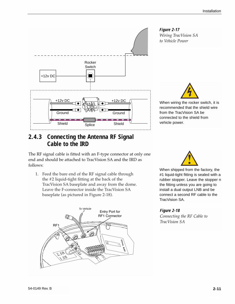
Figure 2-17 on the following page illustrates the internal wiringarrangement for TracVision SA within the vehicle, including thesupplied rocker switch. When wiring the rocker switch, it isrecommended that the shield wire from the TracVision SA beconnected to the shield from vehicle power.
Shield
Red
Black
Brown/White
Orange/White
White/Orange
Green/White
White/Blue
Blue/White
Shield
Grnd
+12v DC
Grnd
RTN
PC_RXD
PC_TXD
RTN
IRD_RXD
IRD_TXD
Grnd
1
2
3
4
5
6
7
8
9
10
Figure 2-16Proper Terminal Strip Wiring
Arrangement – Power Cable
Figure 2-15Proper Wire-to-Terminal
Connection
Insulation
Terminal Connector
1/4˝
DO NOT leave an extra length ofcable within the baseplate as aservice loop. All service loopsshould be kept inside the vehicle’scable access.
2-11
Installation
54-0149 Rev. B
2.4.3 Connecting the Antenna RF Signal Cable to the IRD
The RF signal cable is fitted with an F-type connector at only oneend and should be attached to TracVision SA and the IRD asfollows:
1. Feed the bare end of the RF signal cable throughthe #2 liquid-tight fitting at the back of theTracVision SA baseplate and away from the dome.Leave the F-connector inside the TracVision SAbaseplate (as pictured in Figure 2-18).
Figure 2-17Wiring TracVision SAto Vehicle Power
+12v DC
RockerSwitch
+12v DC
Ground
��������yyyyyyyy
Shield
��������yyyyyyyy
+12v DC
Ground
ShieldSplice
When wiring the rocker switch, it isrecommended that the shield wirefrom the TracVision SA beconnected to the shield fromvehicle power.
Figure 2-18Connecting the RF Cable toTracVision SA
Entry Port for
RF1 Connector
RF1
To Vehicle
When shipped from the factory, the#1 liquid-tight fitting is sealed with arubber stopper. Leave the stopper nthe fitting unless you are going toinstall a dual output LNB and beconnect a second RF cable to theTracVision SA.

2-12
A Guide to TracVision SA
2. Connect the RF signal cable’s F-connector to theplug labeled RF1.
3. Feed the bare end of the RF signal cable and passthrough the cable hole drilled earlier and into thevehicle.
4. Attach the provided F-connector to the end of theRF signal cable inside the vessel as illustrated inFigure 2-19a-d, using an Augat Snap ‘n SealCrimp/Strip tool to lock the connector on thecable.
a. Slide compression fitting onto raw cable before beginning connector termination.
b. Twist and break off connector body.
c. Use Augat tool to strip center conductor andtrim back overall jacket. Do not cut throughbraid.
d. Slide connector body onto the prepared cable. Slide the compression fitting up intothe connector body. Use Augat tool to snapon the connector.
5. Attach the cable to the IRD connector labeledSATELLITE IN.
Figure 2-19a-dAttaching the KVH-provided
F-connector to an RF Cable
Twist
0.25
0.25
KVH has provided an F-connectorfor use with the TracVision SA. Thisconnector specifically requires theAugat Snap ‘n Seal Crimp/StripTool, part number IT1000.
If you do not have this tool, you willneed to purchase a silicone-filled,weatherproof F-connector (RadioShack Part Number 278-236 orequivalent) to use instead.
2-13
Installation
54-0149 Rev. B
2.5 Checking Out the SystemPower up the TracVision SA system and IRD and observemessages on your TV screen to verify proper operation. Somemessages originate in the IRD, others are generated in theTracVision SA circuits.
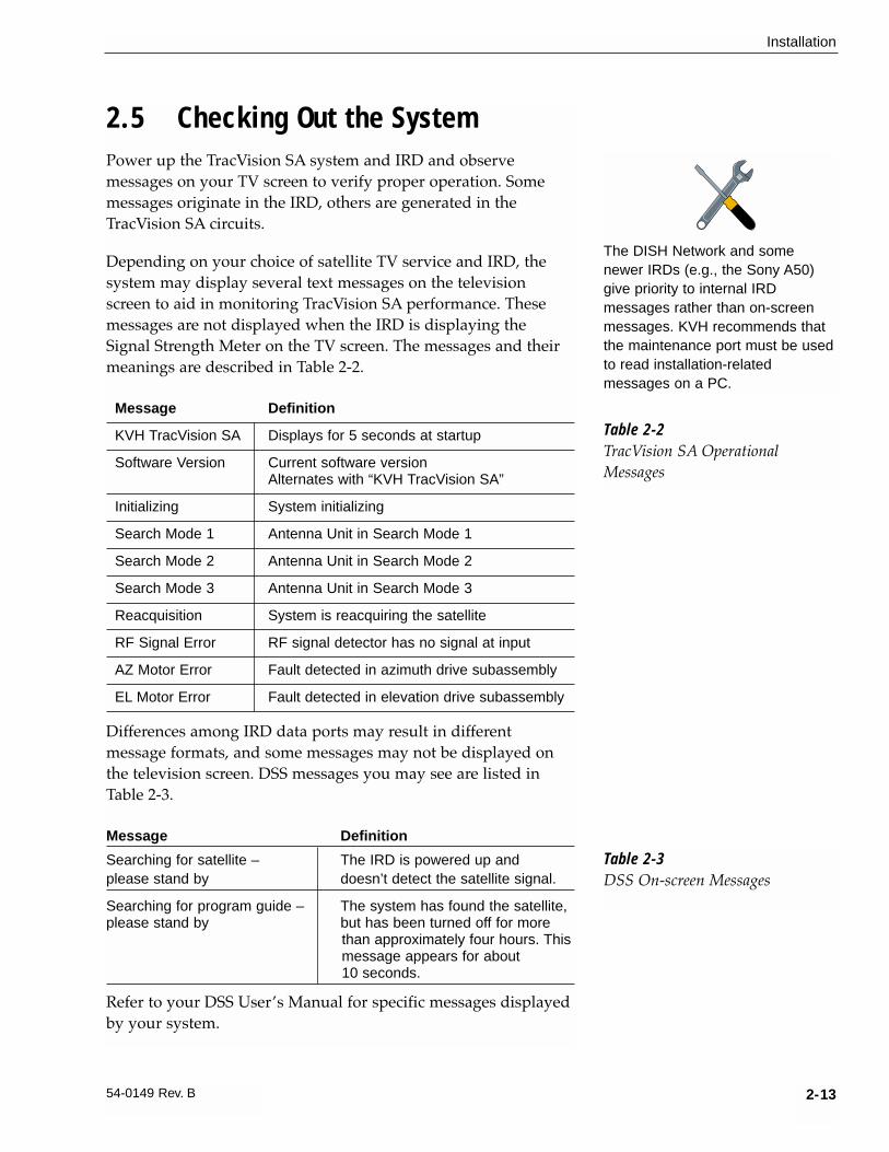
Depending on your choice of satellite TV service and IRD, thesystem may display several text messages on the televisionscreen to aid in monitoring TracVision SA performance. Thesemessages are not displayed when the IRD is displaying theSignal Strength Meter on the TV screen. The messages and theirmeanings are described in Table 2-2.
Message Definition
KVH TracVision SA Displays for 5 seconds at startup
Software Version Current software versionAlternates with “KVH TracVision SA”
Initializing System initializing
Search Mode 1 Antenna Unit in Search Mode 1
Search Mode 2 Antenna Unit in Search Mode 2
Search Mode 3 Antenna Unit in Search Mode 3
Reacquisition System is reacquiring the satellite
RF Signal Error RF signal detector has no signal at input
AZ Motor Error Fault detected in azimuth drive subassembly
EL Motor Error Fault detected in elevation drive subassembly
Differences among IRD data ports may result in differentmessage formats, and some messages may not be displayed onthe television screen. DSS messages you may see are listed inTable 2-3.
Message Definition
Searching for satellite – The IRD is powered up andplease stand by doesn’t detect the satellite signal.
Searching for program guide – The system has found the satellite,please stand by but has been turned off for more
than approximately four hours. Thismessage appears for about 10 seconds.
Refer to your DSS User’s Manual for specific messages displayedby your system.
The DISH Network and somenewer IRDs (e.g., the Sony A50)give priority to internal IRDmessages rather than on-screenmessages. KVH recommends thatthe maintenance port must be usedto read installation-relatedmessages on a PC.
Table 2-2TracVision SA OperationalMessages
Table 2-3DSS On-screen Messages

2.6 Completing the InstallationProcess
If the system has initialized properly and is functioning, replacethe radome on the baseplate (labels on the sides), securing it withthe eight pan head screws and flat washers removed at the startof the installation process.
As noted previously, while some DIRECTV IRDs offer on-screenmessages, it is recommended that a PC be available for allinstallations of both DIRECTV and EchoStar. This will permit theinstaller to record the TracVision SA startup sequence to verifythat the unit is functioning within specified parameters. Baselinestartup parameters (with optimal ranges) have been provided inAppendix E.
2.7 Configuring TracVision SA forRemote Satellite Dish Operation
In some campground locations, dense foliage will block thesatellite signal. In these situations, a remote portable antennamay be the only solution to satellite signal reception.
The wiring option for the remote dish is very simple and should be installed when the TracVision is installed. A high-quality “A/B switch” should be used to change from TracVisionto remote antenna operation. The recommended wiringarrangement for remote dish operation is illustrated in Figure 2-20.
2-14
A Guide to TracVision SA
If a need does arise to paint theradome, ONLY use non-metallicautomotive paint to avoiddegrading the RF signal strengthand the reception quality.
IRD
A/B Switch
A B
A B
Common
TV Out
SAT in
TracVision SA
Remote Dish
Figure 2-20Remote Dish Wiring
Configuration

3 OperationThe TracVision SA system is easy to use. Antenna unitinitialization and satellite acquisition is automatic and does notrequire any operator intervention.
To use the TracVision SA system, the vehicle must be stationary.Once the vehicle is parked:
1. Turn on the IRD and the television.
2. Apply operating power to the antenna unit.
Refer to your IRD user manual for complete operatinginstructions for the IRD.
A clear line of sight to the satellite helps ensure that the antennacan acquire and track the satellite.
The system carries out a number of automated steps at startup.For reference, these steps are outlined in Table 3-1.
Step Actions
Antenna Unit Initialization The microprocessor circuitry does abasic self-test of the hardware andsoftware associated with theantenna unit.
IRD Identification The microprocessor next queriesthe IRD to determine whether it is aDIRECTV or DISH Network IRD.Based on the IRD type, the systemwill then set various systemvariables to ensure that the correctsatellite is found during SearchMode.
Satellite RF Threshold The antenna is pointed at the north,south, east and west horizons todetermine the background noiselevel and to calculate the minimumsignal level required for satelliteacquisition.
Satellite Search Modes The system design includes threesearch modes to acquire thesatellite.
Search Mode 1 The antenna makes three completerevolutions at the saved elevation.
3-1
Operation
54-0149 Rev. B
As part of the startup process, theTracVision SA system will default toChannel 200, a program directory.This is the system’s means ofverifying that it has identified and istracking the correct satellite.
Once Channel 200 appears, wait atleast another 30 seconds beforechanging the channel to ensurethat the system has completed itsstartup routine.
Table 3-1TracVision SA AutomatedProcedures

Step Actions
Reacquisition Search The antenna will search in a(Search Mode 2) “window” of 6˚ around the satellite’s
last known elevation.
Search Mode 3 The antenna conducts a completesky search, making continuousrevolutions at steadily increasingelevations (from 20˚ to 70˚).
Fine-tuning/Satellite Verification When a signal is detected, theantenna interrupts the search modeand begins a procedure to fine-tunethe position for maximum signalstrength. When the signal peak isfound, the IRD is queried todetermine if it can decode thepeaked signal. If it is able todecode and lock onto the signal,then the system enters park mode.
Using Your TracVision SA When Parked
When your vehicle is stopped, it is not necessary for theTracVision SA to be turned on. After parking your vehicle andconfirming that the antenna is receiving the satellite signal, youmay turn off the TracVision SA unit to avoid unnecessary use ofpower. The antenna will continue to receive the satellite TVsignals and relay them to the IRD.
“Instant On” Operation
As part of its operation, TracVision SA routinely saves thesatellite position to memory and retains it when the system isturned off. When TracVision SA is powered up, the system looksat the satellite’s last saved position. If the vehicle has not changedits location, the antenna will immediately acquire the satellite andreceive the signal without initializing the antenna.
If the vehicle moves after TracVision SA is turned off, theAntenna Unit will quickly carry out its normal initializationroutine to reacquire the satellite.
3-2
A Guide to TracVision SA
It is highly recomended that youturn off the TracVision SA prior tomoving the vehicle. TracVision SAwill not track a satellite while thevehicle is in motion.

4 TroubleshootingThe troubleshooting matrix shown in Table 4-1 identifies sometrouble symptoms, their possible causes, and references totroubleshooting solutions.
4.1 Causes and Remedies forCommon Operational Issues
There are a number of common issues that can affect the signalreception quality or the operation of the TracVision SA. Thefollowing sections address these issues and potential solutions.
4-1
Troubleshooting
54-0149 Rev. B
Table 4-1Troubleshooting Matrix
Antenna non-functional X
No IRD status message X X X X
No picture on TV set X X X X X X
Intermittent picture for short intervals X X X X X X X
System will not find satellite X X X X X X X X
Snowy television picture X
IRD locks up X X
Outsidesatellitecoveragezone(Section4.1.3)
IRDdataportorcable/wiring(Section4.2.1)
LNBassemblyfaulty
(Section4.3)
IRDfaulty
(Section4.2.5)
Satellitesignal blocked(Section4.1.2)
Incorrectorloose
RFconnectors(Section4.1.4)
ACpowerfluctuating(Section4.2.2)
PO
SS
IBLE
CA
US
E (A
ND
SO
LUTI
ON
)
SYMPTOM EchoStarIRDcommissioning(Section4.2.3)
FailedIRDstatuscheck
(Section4.2.4)
Blownfuse
orlack
ofpower(Section4.1.1)

4.1.1 Blown Fuse or No PowerIf the Antenna Unit is installed but entirely non-responsive, thereare two key factors to check as part of the troubleshootingprocess:
1. Blown Fuse – The Antenna Unit is equipped witha fuse mounted on its CPU Board. If this fuse hasblown or been broken, the Antenna Unit will notoperate. Refer to Section 5.4.1, “PCB Removal andReplacement,” for details on the fuse location andhow to access the CPU Board.
2. Wiring – If the system has been improperly wired,it will prevent the Antenna Unit from operatingcorrectly. Refer to Section 2.4.2, “Connecting theAntenna to Vehicle Power,” for complete systemwiring information.
4.1.2 Satellite Signal BlockedSatellite signals can be blocked or degraded by trees andbranches, buildings, mountains, overpasses, or equipment on thevehicle itself. Refer to Section 2.2, “Choosing the Best Location,” tomake certain that the TracVision SA unit is in the optimallocation. Simply moving the vehicle to clear an externalobstruction will also restore signal quality.
4.1.3 Outside Satellite Coverage ZoneTracVision SA will provide outstanding reception throughout theentire coverage area for your satellite television service of choice.However, signal quality can be degraded as you approach thefringe coverage areas (e.g., Northern Maine). Refer to yoursatellite television service manual to check the viable coveragearea.
4.1.4 Incorrect or Loose RF ConnectorsAs part of preventive maintenance (described in Section 5,“Maintenance,”) KVH recommends checking the Antenna Unitcable connections. A loose RF connector can reduce the signalquality. Refer to Section 2.4.3, “Connecting the Antenna RF SignalCable to the IRD” for directions on proper Antenna Unit to RF cabling.
4-2
A Guide to TracVision SA
Baseline RF levels are included aspart of the startup sequenceprovided in Appendix E.
On-screen messages are notavailable with the DISH Networkand some newer IRDs (e.g., theSony A50).

4.2 IRD TroubleshootingThe IRD that was provided with your satellite television servicemay also be the cause of less-than-ideal operation.
4.2.1 IRD Data Port or Cable/WiringRefer to Section 2.4.1, “Connecting the Antenna Unit Data Cable tothe IRD” and your IRD user manual to confirm that the IRD isproperly connected to the Antenna Unit and the television.
4.2.2 AC Power FluctuatingIf the system periodically displays a picture for less than oneminute, then enters Search Mode 1, the IRD data port may belocked up as the result of power fluctuations and will require areset. This can be verified by hooking up a PC to the data portand checking for error messages. Reset must be done by:
1. Completely shutting down DC power to theantenna.
2. Remove the AC source, either at the breaker or byunplugging the IRD.
3. Wait at least 10 seconds before restoring powerfirst to the IRD and then to the antenna.
4.2.3 EchoStar IRD Commissioning CheckIf you have purchased a DISH Network system, there is a chancethat your EchoStar IRD will fail to acquire the satellite when youfirst activate it. This has been known to happen in IRDs that havenot been commissioned within several months of theirmanufacture. Appendix D provides the manual satelliteacquisition and commissioning procedure.
4.2.4 Failed IRD Status CheckAs detailed in Appendix E, TracVision SA completes a detailedstartup routine whenever it is turned on. One of the first checksis the IRD status test. As noted in the typical startup cycles, theexpectation is that the IRD and its communications link toTracVision SA will pass this test. There are, however, twoalternate results, each indicating a slightly different problem.
4-3
Troubleshooting
54-0149 Rev. B
The long-term fix, typically done atoriginal system installation, is toinstall an Uninterruptible PowerSupply (like those available for usewith computer systems) on the IRD.Be sure to specify a UPS withadequate available current for alldevices attached to it. (An IRDdraws approximately 200 watts.)

Test Result: NONE
If the system tests achieves a result of NONE, there is nocommunication at all between the antenna unit and the IRD.
Solution
Check to be certain the IRD and TracVision SA are connectedproperly at the low-speed data port. Refer to Section 2.4,“Connecting the Antenna Unit,” for correct Antenna Unit to IRD wiring procedures and diagrams. After verifying theconnection, cycle the power on and off and review the startuptest results.
Test Result: UNKNOWN
In the instance of a result of UNKNOWN, a communications linkexists, but the data received by the antenna unit is garbled andunrecognizable.
Solution
As with a result of NONE, first check to be certain the IRD andTracVision SA are connected properly at the low-speed data port.Refer to Section 2.4, “Connecting the Antenna Unit,” for correctAntenna Unit to IRD wiring procedures and diagrams. Afterverifying the connection, cycle the power on and off and reviewthe startup test results. If this does not initially succeed, refer toSection 4.2.2, “AC Power Fluctuating,” and follow the IRD resetprocedure.
4.2.5 IRD FaultyIn the case of a faulty IRD, refer to your IRD user manual forservice, replacement, and warranty information.
4.3 LNB FaultsSection 5, “Maintenance,” provides detailed instructions forauthorized service personnel who may be required to replacethe TracVision SA LNB.
4-4
A Guide to TracVision SA

4.4 Computer DiagnosticsTracVision SA has been designed to provide diagnostic readoutsviewed on the TV screen (DSS only) or on a personal computerhaving an RS-232 serial communication port. If you are unable toisolate a system problem with the foregoing troubleshootingtools, set up for computer diagnostics as described below. Systemproblems will most likely be found somewhere through thediagnostic readouts.
The diagnostics procedure requires terminal emulation softwaresuch as PROCOMM, Windows Terminal, or Windows 95Hyperterminal. Use the settings appropriate to your application.
1. Connect one end of the PC cable to the DB9connector on the switchplate. Connect the otherend to the serial port on the PC (a 9-pin/25-pinconnector adapter may be needed for some PCs).
2. Open the terminal emulation software andestablish the following settings:
• 9600 baud
• no parity
• 8 data bits
• 1 start bit
• 1 stop bit
• no flow control
3. Apply power to the TracVision SA system andallow the system to complete full initialization.Data should be scrolling on the PC display toidentify any system problems detected. If no datais seen, recheck your connections and the terminalsoftware setup.
4.5 Maintenance Port ParserCommands
TracVision SA system parser commands are detailed in Appendix F.
4-5
Troubleshooting
54-0149 Rev. B
Most terminal emulation programshave a parameter for localcharacter echo. Select thisparameter to see what is beingtyped without any system delay.


5-1
Maintenance
54-0149 Rev. B
5 Maintenance5.1 Warranty/Service InformationKVH Industries, Inc. warrants the KVH product purchasedagainst defects in materials for a period of TWO (2) years andagainst labor costs for a period of ONE (1) year from the date oforiginal retail purchase by the original purchaser. It is thecustomer’s responsibility to verify the date of purchase byreturning the warranty card included with the product to KVHwithin 30 days of purchase, or by providing a copy of a datedsales receipt for the KVH product under warranty with thewarranty claim. If this date cannot be verified, the warrantyperiod will begin 30 days after the date of manufacture of theoriginal product purchased.
For additional information on KVH warranty, repair, and liabilitypolicies, please refer to the complete warranty statementprovided at the conclusion of this manual.
5.2 Preventive MaintenanceTracVision SA requires minimal preventive maintenance. Thefollowing tasks are sufficient to maintain peak performance.
Monthly• Wash the exterior of the radome and baseplate
assembly with fresh water; a mild detergent maybe added to remove grime. Do not spray theradome directly with high-pressure water.
• Do not apply abrasive cleaners or volatile solventssuch as acetone to the ABS radome.
Annually• Remove the radome and examine the interior of
the Antenna Unit for signs of corrosion, looseconnections, or frayed or broken wires.
• Clean and wax the radome.
• Visually inspect the elevation drive shaft to becertain that it moves easily and is clear of grit anddebris. Clean and lubricate with silicone or whitelithium grease as required.
The serial number of yourTracVision SA will be requiredduring any troubleshooting orservice calls. You will find the serial number on the inside frontcover of this manual as well as infront of the antenna reflector on the rotating plate.

5-2
A Guide to TracVision SA
5.3 Replaceable PartsTracVision SA has been designed with durability and lowmaintenance in mind. If you experience an operating problem orotherwise require technical assistance, contact your localauthorized TracVision SA dealer/installer first. Have the AntennaUnit serial number ready with a list of the trouble symptoms. Ifan authorized dealer/installer is not located nearby, contact thefactory directly at the telephone, facsimile, or e-mail listingsinside the front cover.
Replacement part numbers for units that can be serviced in thefield are listed in Table 5-1. These parts may be obtained fromany KVH authorized dealer/installer.
Part Name Part Number
Radome Assembly 02-0953-02
Power Cable 32-0590-30
Data Cable 32-0591-30
EchoStar Adapter Unit * 02-0899
CPU PCB 02-0954
RF PCB 02-0826
System Fuse 16-0017-4000
LNB 19-0194
* Optional, purchased separately
It is recommended that all other technical difficulties be resolvedby returning the TracVision SA unit to an authorized serviceprovider.
Table 5-1Field Replaceable Units
Should the fuse ever need to bereplaced, TracVision SA uses a 5x20mm, 4-amp, 250-volt fast-blow fuse.

5-3
Maintenance
54-0149 Rev. B
5.4 Field Replaceable UnitProcedures
The following subsections provide detailed procedures forrepairing or swapping out field replaceable units. The proceduresrefer to labeled items presented on the following isometricdiagrams, which are based on KVH assembly drawings.
Figure 5-1Antenna, PCB, and Rotating Plate
2
33
60
21
1
11
14 7
8
Elevation Axis Motor Shaft
Figure 5-2Close-up of Linear Actuator, Pivot Bracket, and Pin
Always lift the antenna unit bythe gray baseplate, never by theradome or any portion of theantenna assembly!

5-4
A Guide to TracVision SA
Figure 5-4Close-up of RF Detector,
PCB, and Cover 2
59
Apply clamp directly behindferrite as shown
30
11
21
1
33
From Antenna Gyro
Figure 5-3Antenna Assembly

5-5
Maintenance
54-0149 Rev. B
5.4.1 PCB Removal and Replacement
Estimated Time to Repair: 1⁄2 hour
The microprocessor PCB assembly (Item 1) is protected by a cover (Item 21) fastened to the rotating plate (Item 11) – Fig. 5-1. The cover must be removed to gain access to the main power fuse and the PCB assembly.
1. Remove quick release pin (Item 14) from actuatorpivot bracket (Item 8) – Fig. 5-2.
2. Remove shaft from linear actuator (Item 7) – Fig. 5-2.
3. Remove 16 pan head screws (Item 60) from thecover flanges. Remove PCB cover – Fig. 5-1.
4. Remove cable connectors from PCB.
5. The PCB is mounted to the rotating plate with 10pan head screws. Figure 5-5 illustrates the PCBarrangement and connector locations.
6. Reverse this process to install the replacementPCB. Reinstall all cable connectors removed inStep 4.
7. Carry out the LNB calibration procedure (Section 5.4.3).
Figure 5-5PCB Connector Locations – Rear View (not to scale)
J5J3
J11J9
J2 J1
J4
Fu
se
J3
ToIRD
FromLNB
Pan Head Screws
TracVision SA is equipped with a5x220 mm, 4-amp, 250 volt fast-blow fuse, which is mounted on thePCB. To access and replace thefuse, remove the PCB cover.
When carrying out maintenance on the PCB, be sure to not dropany of the small screws inside themechanism. If a screw is lost withinthe baseplate, it must be retrievedto avoid causing any damage whenthe unit rotates.

5-6
A Guide to TracVision SA
5.4.2 RF Detector
Estimated Time to Repair: 1⁄2 hour
The RF Detector PCB (Item 2) receives operating voltages fromboth the CPU board and the IRD (via the RF cable) – Fig. 5-1.Ensure that all power is turned off before proceeding.
1. Remove 2 RF connectors from the coaxial fittingson the PCB. Tag the cables to ensure that they arereturned to the same connectors.
2. Remove the Molex connector from J3 – Fig. 5-5.
3. Remove 3 pan head screws (Item 33) – Fig. 5-4.Remove the RF Detector PCB from the rotatingplate.
4. Installation of the replacement RF Detector is thereverse of this procedure. Be sure that the RFcables are restored to their original positions. Besure that the center conductor pin is centered inthe connector before tightening the collar.
5.4.3 Antenna LNB Replacement
Estimated Time to Repair: 1⁄2 hour
The LNB (Item 19) receives preamplifier operating power fromthe IRD via the RF Detector PCB – Fig. 5-3. Be certain that theIRD is disconnected from its power source before removing orreconnecting the LNB.
1. Disconnect both RF coaxial connectors at the LNB.Remove 4 pan head screws and washers (Items 57and 58) – Fig. 5-3.
2. Remove LNB clamp (Item 23) – Fig. 5-3.
3. Remove LNB.
4. Replacement is the reverse of this procedure.Check the rotation to ensure that the LNB is notstriking any wires or the baseplate.
Antenna LNB Normalization and Stability Test1. Type HALT<cr> to put the system into Idle Mode.
2. Type DEBUGON<cr> to put the system intoDebug Mode.
When replacing the LNB, makecertain to restore it to its originalorientation, as shown in Figure 5-3.
Familiarity with the PC diagnosticapplication is required to carry outthis procedure. Refer to Table 2,Manual Positioning Commands, inAppendix F, Maintenance PortParser Commands, for furtherdetails.

5-7
Maintenance
54-0149 Rev. B
3. Use the PC 2, 4, 6, and 8 keys along with theSignal Strength Display Meter on the TV screen topeak the RF Signal.
4. Type =CALLNB<cr> to start the LNBNormalization Function.
Note: The CALLNB Function requires the antennato be pointed directly at the satellite peak beforeperforming this routine.
5. The system must respond with the followingmessage: CALLNB: PASS. If the system displaysCALLNB: FAIL, return to step 1 and retry theprocedure, making sure to achieve the highestpossible RF signal peak.
6. Record the Cold Sky Average and the RFGAINvalue reported in step 5.
7. Type ZAP<cr>. The system will re-initialize usingthe new RFGAIN and RFOFFSET scale factorsdisplayed following step 5.
8. Wait for the system to perform the backgroundnoise calculation. Read the Average Noise Levelvalue from the messages transmitted out themaintenance port. This value must be greater than300 and less than 1300. An example of the messagesequence and format is as follows:
*** Averaging Background Noise ***
Average Noise Level = 750
Noise Threshold = 1450
9. Wait for the system to search for, find the satellite,enter Tracking Mode and track the satellite for aminimum of 30 seconds. Record the average RFsignal value reported from the +POS: AZ, EL, RFmessages. An example of the message sequenceand format is as follows:
+POS: 154.5 33.2 2521
10. The RF signal values while tracking shall begreater than 2000 and less than 3000.

5-8
A Guide to TracVision SA
5.4.4 EchoStar Adapter Replacement
Estimated Time to Repair: 1⁄2 hour
Use the following procedure to replace the EchoStar Adapter:
1. Remove power from Antenna and unplug IRDfrom AC power.
2. Observe static precautions.
3. Unscrew and remove DB9 cable connector fromthe Adapter.
4. Unscrew thumbscrews securing Adapter to IRD.
5. Carefully remove Adapter from IRD card edge.
6. Install new Adapter on the IRD card edge. Securethe Adapter and reinstall cable.
5.5 Preparation for ShipmentEstimated Time: 1 hour
If it is necessary to repack the Antenna Unit for shipment, theshipping restraints removed during installation must be replaced.Follow these steps to reinstall the restraints.
1. Rotate the antenna unit so that the LNB is facingforward (away from the liquid-tight fittings).
2. Attach the three restraints to the baseplate usingthe 1⁄4˝-20 x 5⁄8˝ long hex screws (provided as part ofthe kitpack), washers, and nuts (removed fromshipping restraint during installation) as picturedin Figure 5-6 on the following page.
3. Place the antenna bracket on the forward shippingrestraint.
4. Secure the forward restraint and bracket bywrapping three tie-wraps around the bend in theforward restraint and the antenna bracket (at theend of the LNB bracket).
When rotating the azimuthmechanism by hand, go slowly!Hitting the mechanical stops withexcessive force will damage theazimuth limit switch.

5-9
Maintenance
54-0149 Rev. B
Figure 5-7Securing the ForwardShipping Restraint
2 tie-wraps used
to secure LNB arm
Forward Shipping Restraint
Forward Shipping Restraint
Nuts and Washers
Hex Screws and Washers
Figure 5-6Attaching the Shipping Restraintsto the Antenna Baseplate


Appendix ASystem SpecificationsPhysical Characteristics
Power 11-16 volts DC @ 2.5 ampsnominal, 3.5 amps peak
Dimensions/Weight 31˝ wide x 14.5˝ high/ 33 lbs
LNB Single Output
Maintenance Port 9600 bps, 8,N,1,EIA, RS232
Pointing System
Elevation Range 15˚ to 75˚
Azimuth Range 720˚
Position Repeatability 0.1˚
Environmental
Operating Temperature -25˚C to +55˚C
Storage Temperature -40˚C to +85˚C
Humidity to 100 percent
Table A-1TracVision SA SystemSpecifications
A-1
System Specifications
54-0149 Rev. B


Appendix BFunctional Block Diagram
B-1
Functional Block Diagram
54-0149 Rev. B
ElevationMotor
AzimuthMotor
TV
DSS orEchoStar
IRD
PC
Elevation Mechanism
Azimuth Mechanism
LNB
CPU/Motor Driver/Power Supply
AzimuthMotorSwitch
RFDetector
Power+12v DC
PowerSwitch
RF1
IRD
Maint.
Power
TracVision SA Antenna Unit Components/WiringIn-vehicle Components
TerminalConnectors
Cable AssignmentsRF1.........................RF Cable (32-0589-30)
IRD/Maint................Data Cable (32-0591-30)
Power......................Power Cable (32-0590-30)
ElevationLimitSwitch


Appendix CData Cable WiringC.1 Wiring TracVision SA to a
15-pin Data ConnectorIn some instances, the IRD provided with a satellite TV servicemay be equipped with a 15-pin connector (DB15 wide-band dataport), rather than a 9-pin connector (DB9 low-speed data port).There are two methods that will allow a TracVision SA system tofunction through a DB15 port.
Splicing a DB15 Connector to the Data Cable
It is possible to splice a DB15 connector to the TracVision SA datacable after removing the male DB9 connector. The alternatewiring arrangement is as follows:
DB9 Pin Wire Color Function DB15 Pin
2 Blue/White TXD 14
3 White/Blue RXD 6
5 Green/White GND 7
Creating a DB9-to-DB15 Adapter
It is also possible to construct a DB9-to-DB15 adapter that willremove the need to cut and splice the data cable. Whenconstructing such an adapter, follow the DB9-to-DB15 pinarrangement detailed in Table C-1.
C-1
Wiring TracVision SA to a 15-pin Data Connector
54-0149 Rev. B
Table C-1Alternate Wiring Arrangement forTracVision SA Data Cable to DB15(15-wire) Connector

C.2 DB9 Data Connector Pin Assignments
During the troubleshooting or maintenance process, it maybe necessary to check the DB9 data connectors to ensure thatit is operating properly. With that in mind, Figure C-1 and TableC-2 detail the pin assignments for both the male and female DB9connectors.
From Connector Wire Color Function
Male Connector Pin 2 Blu/Wht DSSTXD
Male Connector Pin 3 Wht/Blu DSSRXD
Male Connector Pin 5 Grn/Wht DSSGND
Female Connector Socket 2 Org/Wht PCRXD
Female Connector Socket 3 Wht/Org PCTXD
Female Connector Socket 5 Brn/Wht PCGND
C-2
A Guide to TracVision SA
Table C-2DB9 Pin Functions
and Color Code
Pin 1
Male Connector(to IRD)
Socket 1
Female Connector(to PC)
Figure C-1DB9 Male and Female
Connector Arrangement
Appendix DEchoStar IRD CommissioningProcedureIf you have purchased a DISH Network system, there is a chancethat your EchoStar IRD will fail to acquire the satellite when youfirst activate it. This has been known to happen in IRDs that havenot been commissioned within several months of theirmanufacture. The following process is a manual method ofacquiring the satellite for the first time so that the IRD candownload the most up-to-date satellite and programming data,allowing it to automatically acquire the satellite from then on.
Please refer to your EchoStar IRD user manual for completeinstructions on the IRD, the remote control, and the commandscreens.
Manual Satellite Acquisition and IRD Commissioning1. Turn on TV and EchoStar IRD.
2. Using EchoStar remote, press MENU.
- The Main Menu will come up on the Screen.
3. Select #6, System Setup.
4. Select #1, Installation.
5. Select #1, Point Dish/Signal.
- The Signal Strength Screen will appear.
6. Using remote, select the zip code box on thescreen, and input the local zip code.
- The screen will show you the Azimuth andElevation to the satellite. Write this down.
7. Connect a PC to the data port.
8. Turn on the TracVision SA.
9. Type HALT <CR> after receiving the message *** Entering Search Mode 1 ***.
10. Type in the elevation that you obtained in step 6.
D-1
EchoStar IRD Commissioning Procedure
54-0149 Rev. B
It will be necessary to have a PCavailable to complete the manualacquisition and commissioningprocedure.

- Type EL,xxx<CR>(e.g., Elevation of 30.2° = EL,302<CR>)
11. Using a compass, take a bearing on an object thatis approximately on the azimuth obtained in step6.
12. Type in an azimuth that points the antenna in thedirection of the object selected in step 11.
- Type AZ,xxxx<CR>(e.g., Azimuth of 233° = AZ,2330<CR>)
- Valid azimuth range is 0-360° (0000-3600)
13. Check to see if there is signal strength on theSignal Meter Screen.
14. Move antenna counter-clockwise in 5° incrementsuntil signal strength is acquired. If you do not findsatellite, point the antenna at the object selected instep 11 and move antenna clockwise in 5°increments until signal strength is acquired.
15. Once satellite is found, fine tune azimuth in 1°increments for maximum signal strength.
16. Fine tune in elevation in 1° increments formaximum signal strength.
17. Once the satellite is found, turn the EchoStar IRDoff, using the power button on the infrared remote.Do not turn off the IRD using the front panel. LeaveIRD in standby mode for approximately 5 minutes.The IRD will now download new software fromthe satellite.
- To verify that the IRD has been updated, put theIRD into the Signal Strength Screen mode, andthree satellite options will appear on the left sideof the screen: 61.5° West, 119° West, 148° West.Your EchoStar IRD is now updated.
18. Turn the TracVision SA off and then on. TheEchoStar IRD will now communicate with theTracVision SA system. To verify this, monitor dataport information. The following message willappear.
*** Initializing IRD ***
IRD STATUS: PASS ECHO
D-2
A Guide to TracVision SA
The Signal Strength Meter islocated on the bottom of the “PointDish and Signal Strength” screen.This Signal Strength Meter is Redin color, and turns Green when theproper satellite is located.
Turning the IRD off with the remoteputs IRD in standby mode. Turningthe IRD off from the front panelshuts IRD off.
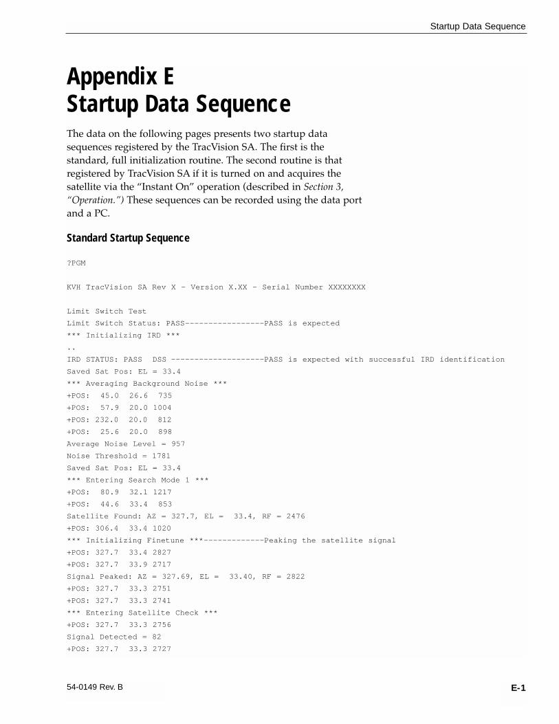
Appendix EStartup Data SequenceThe data on the following pages presents two startup datasequences registered by the TracVision SA. The first is thestandard, full initialization routine. The second routine is thatregistered by TracVision SA if it is turned on and acquires the satellite via the “Instant On” operation (described in Section 3,“Operation.”) These sequences can be recorded using the data portand a PC.
Standard Startup Sequence
?PGM
KVH TracVision SA Rev X - Version X.XX - Serial Number XXXXXXXX
Limit Switch Test
Limit Switch Status: PASS-----------------PASS is expected
*** Initializing IRD ***
..
IRD STATUS: PASS DSS --------------------PASS is expected with successful IRD identification
Saved Sat Pos: EL = 33.4
*** Averaging Background Noise ***
+POS: 45.0 26.6 735
+POS: 57.9 20.0 1004
+POS: 232.0 20.0 812
+POS: 25.6 20.0 898
Average Noise Level = 957
Noise Threshold = 1781
Saved Sat Pos: EL = 33.4
*** Entering Search Mode 1 ***
+POS: 80.9 32.1 1217
+POS: 44.6 33.4 853
Satellite Found: AZ = 327.7, EL = 33.4, RF = 2476
+POS: 306.4 33.4 1020
*** Initializing Finetune ***-------------Peaking the satellite signal
+POS: 327.7 33.4 2827
+POS: 327.7 33.9 2717
Signal Peaked: AZ = 327.69, EL = 33.40, RF = 2822
+POS: 327.7 33.3 2751
+POS: 327.7 33.3 2741
*** Entering Satellite Check ***
+POS: 327.7 33.3 2756
Signal Detected = 82
+POS: 327.7 33.3 2727
E-1
Startup Data Sequence
54-0149 Rev. B

E-2
A Guide to TracVision SA
+POS: 327.7 33.3 2734
+POS: 327.7 33.3 2748
Signal Detected = 81
+POS: 327.7 33.3 2731
+POS: 327.7 33.3 2712
+POS: 327.7 33.3 2674
+POS: 327.7 33.3 2713
Tracking DSS satellite at 101.5W
+POS: 327.7 33.3 2665
IRD Signal Quality = 79
+POS: 327.7 33.3 2681
+POS: 327.7 33.3 2708
Saved Sat Pos: AZ = 327.70, EL = 33.34
“Instant On” Startup Sequence
?PGM
KVH TracVision SA Rev K - Version 5.05 - Serial Number 12345678
Instant On--------------------------------System skips limit switch test
Limit Switch Status: PASS-----------------PASS is expected
*** Initializing IRD ***
...
IRD STATUS: PASS DSS --------------------PASS is expected with successful IRD identification
Saved Sat Pos: EL = 33.3
*** Initializing Finetune ***-------------Peaking the satellite signal
+POS: 360.0 33.9 2622
Signal Peaked: AZ = 0.00, EL = 33.30, RF = 2674
+POS: 0.0 33.3 2646
+POS: 0.0 33.3 2638
IRD Signal Quality = 79
+POS: 0.0 33.3 2640
+POS: 0.0 33.3 2616
+POS: 0.0 33.3 2614
IRD Signal Quality = 77
CH = 200 XP = 7 HI = 0 LO = 10
+POS: 0.0 33.3 2652
Saved Sat Pos: AZ = 0.00, EL = 33.30
+POS: 0.0 33.3 2617
+POS: 0.0 33.3 2616
IRD Signal Quality = 78
+POS: 0.0 33.3 2610

Appendix FMaintenance Port ParserCommandsTracVision SA system parser commands are parsed when thesystem receives an ASCII carriage return (Hex 0D). An ASCII linefeed (Hex 0A) is permitted but is ignored in any transmittedcommand. All system responses are terminated with an ASCIIcarriage return followed by a line feed and ending with either anacknowledge character (ASCII > (Hex 3E)) or a not-acknowledgecharacter (ASCII ? (Hex 3F)). The parser commands are shownbelow in boldface capital letters but they are not case-sensitive. Inmost cases the command is responded to with an echo; that is, ifyou type ZAP, for example, and press “ENTER,” the response willbe the command you have entered (i.e., ZAP). For other commandsthe response is specific for each command, such as VERSION,STATUS, or HELP.
F.1 System CommandsSoftware Version
Function reports software version
Command VERSION
Argument none
Response KVH TVSA Version XX.XX
System Status Report
Function: reports general system status
Command: STATUS
Argument: none
Response: system status string, (TBD)
Initialize the System
Function: initializes the system (perform a soft reset)
Command: ZAP
Argument: none
Response: echoes the command, then reinitializes the system
F-1
Maintenance Port Parser Commands
54-0149 Rev. B
Table F-1System Commands

F.2 Manual Positioning CommandsTo execute the following commands, first put the Antenna Unit inidle mode by typing HALT and pressing “ENTER.” Positioningcommands may be entered after the antenna comes to rest.
Help on Parser Commands
Function: lists parser commands
Command: HELP
Argument: none
Response: print a list of all parser commands
Azimuth Angle
Function: commands a manual azimuth angle that themechanism moves to
Command: AZ,xxxx (range is 0000-3599)
Argument: desired azimuth angle of the mechanism relative to vehicle reference, or baseplate fwd, 000˚-359.9˚(vehicle-referenced)
Response: echoes the command; mechanism moves at a fixedvelocity
Elevation Angle
Function: commands a manual elevation angle that themechanism moves to
Command: EL,xxx (range is 100-700)
Argument: desired elevation angle of the mechanism relativeto up, or external sensor attitude reference, 10.0˚-70.0˚
Response: echoes the command; mechanism moves at a fixedvelocity
Azimuth CW Step
Function: commands a 0.1 deg CW manual step in azimuthangle
Command: 6
Argument: none
Response: echoes the command
F-2
A Guide to TracVision SA
Table F-2Manual Positioning Commands

Azimuth CCW Step
Function: commands a 0.1 deg CCW manual step in azimuthangle
Command: 4
Argument: none
Response: echoes the command
Elevation UP Step
Function: commands a 0.1 deg UP manual step in elevation angle
Command: 8
Argument: none
Response: echoes the command
Elevation DOWN Step
Function: commands a 0.1 deg DOWN manual step in elevation angle
Command: 2
Argument: none
Response: echoes the command
F.3 Operational CommandsIdle Mode
Function: halts active tracking and conical scan, then enters idle mode
Command: HALT
Argument: none
Response: echoes the command
F-3
Maintenance Port Parser Commands
54-0149 Rev. B
Table F-3Operational Commands

F.4 Target and Signal CommandsReport Target Location
Function: reports the target (satellite) location in the baseplateframe and uses the saved satellite position
Command: TGTLOCATION
Argument: none
Response: Target Location = E XXX, A XXXX
Report RF Signal Strength
Function: reports the modified signal strength from the RF powerdetector circuit, and applies the RF gain and offsetcomputed during LNB calibration
Command: SIGLEVEL
Argument: none
Response: Signal Strength = XXXX
Report IRD Signal Quality
Function: reports the signal strength from the IRD; it uses the lastreceived signal quality and initiates a new signal qualityrequest command from the IRD
Command: SIGQUALITY
Argument: none
Response: Stale Signal Quality = XX
Report IRD Type
Function: reports the IRD connection type as DSS, EchoStar,untested, or none
Command: IRDTYPE
Argument: none
Responses: IRD type has not been tested yet.IRD type is Echostar.IRD type is DSS.IRD type cannot be determined.
F-4
A Guide to TracVision SA
Table F-4Target and Signal Commands

KVH Industries Limited Warranty TracVision SA
Limited Warranty on HardwareKVH Industries, Inc. warrants the KVH product purchased against defects in materials for a period of TWO (2) yearsand against labor costs for a period of ONE (1) year from the date of original retail purchase by the original purchaser.It is the customer’s responsibility to verify the date of purchase by returning the warranty card included with theproduct to KVH within 30 days of purchase, or by providing a copy of a dated sales receipt for the KVH product underwarranty with the warranty claim. If this date cannot be verified, the warranty period will begin 30 days after the date ofmanufacture of the original product purchased.
If you discover a defect, KVH will, at its option, repair, replace or refund the purchase price of the product at no chargeto you, provided you return it during the warranty period, transportation charges prepaid, to the factory direct. Pleaseattach your name, address, telephone number, a description of the problem and a copy of the bill of sale or salesreceipt as proof of date of original retail purchase, to each product returned to warranty service. Alternatively, you maybring the product to an Authorized KVH TracVision Dealer for repair. If the product was installed by an Authorized KVHTracVision Dealer (identified with the KVH Authorized TracVision dealer list), KVH will cover the dealers’ labor chargesfor warranty repairs, provided the dealer contacts KVH for pre-approval of the charges.
This Limited Warranty does not apply if the product has been damaged by accident, abuse, misuse or misapplicationor has been modified without the written permission of KVH; if any KVH serial number has been removed or defaced;or if any factory-sealed part of the system has been opened without authorization.
Return AuthorizationA Return Material Authorization is required prior to returning the product to KVH Industries. Please call our TechnicalSupport Department at (401) 847-3327 or send an e-mail to [email protected] to obtain the RMA number. Write thenumber in large, clear characters on the outside of the box. To avoid confusion and misunderstandings, shipmentswithout an RMA number clearly visible on the outside box will be refused and returned to you at your expense. Ifpossible, use the original box and packing material to protect the equipment from damage in shipment. KVH assumesno responsibility for warranty shipments from the customer to the factory if not shipped in the manner prescribedabove.
THE EXPRESS WARRANTIES SET FORTH ABOVE ARE THE ONLY WARRANTIES GIVEN BY KVH WITHRESPECT TO ANY PRODUCT FURNISHED HEREUNDER; KVH MAKES NO OTHER WARRANTIES, EXPRESS,IMPLIED OR ARISING BY CUSTOM OR TRADE USAGE, AND SPECIFICALLY DISCLAIMS ANY WARRANTY OFMERCHANTABILITY OR OF FITNESS FOR A PARTICULAR PURPOSE. SAID EXPRESS WARRANTIES SHALLNOT BE ENLARGED OR OTHERWISE AFFECTED BY TECHNICAL OR OTHER ADVICE OR SERVICE PROVIDEDBY KVH IN CONNECTION WITH ANY PRODUCT.
KVH's liability in contract, tort or otherwise arising out of or in connection with any product shall not exceed the pricepaid for the product. IN NO EVENT SHALL KVH BE LIABLE FOR SPECIAL, PUNITIVE, INCIDENTAL, TORT ORCONSEQUENTIAL DAMAGES OR LOST PROFITS OR GOODWILL (INCLUDING ANY DAMAGES RESULTINGFROM LOSS OF USE, DELAY IN DELIVERY OR OTHERWISE) ARISING OUT OF OR IN CONNECTION WITH THEPERFORMANCE OR USE OR POSSESSION OF ANY PRODUCT, OR ANY OTHER OBLIGATIONS RELATING TOTHE PRODUCT, EVEN IF KVH HAS BEEN ADVISED OF THE POSSIBILITY OF SUCH DAMAGES.
If any implied warranty, including implied warranties of merchantability and fitness for a particular purpose, cannot beexcluded under applicable law, then such implied warranty shall be limited in duration to ONE (1) YEAR from the dateof the original retail purchase of this product by the original purchaser.
Some states do not allow the exclusion or limitation of implied warranties or liability for incidental or consequentialdamages, so the above limitations may not apply to you. This warranty gives you specific legal rights, and you mayalso have other rights which vary from state to state.

KVH Industries, Inc. 50 Enterprise Center Middletown, RI 02842 U.S.A. Phone: (401) 847-3327 Fax: (401) 849-0045E-Mail: [email protected] Internet: http://www.kvh.com
KVH Europe A/SVed Klaedebo 12 2970 Hoersholm Denmark Phone: +45 45 160 180 Fax: +45 45 867 077
E-Mail: [email protected] Internet: http://www.kvh.com
KVH®, and TracVision® are registered trademarks of KVH Industries, Inc.
TVSA
O/M
Cov
er 3
/00
®