a mirafiori.com guide...Bosch L-Jetronic Fuel Injection Guide FIAT Fuel Injected Engines " First...
19
Bosch L-Jetronic Fuel Injection Guide FIAT Fuel Injected Engines " F irst Edition - July 2004 Brad Artigue a mirafiori.com guide
Transcript of a mirafiori.com guide...Bosch L-Jetronic Fuel Injection Guide FIAT Fuel Injected Engines " First...
Bosch L-Jetronic Fuel Injection GuideFIAT Fuel Injected Engines " F irst Edition - July 2004
Brad Artigue
a mirafiori.com guide
HowL-
Jetro
nicWork
s
Senso
rs
Regulators,In
jectors,
and Pumps
DoubleRelay and Ele
ctronic
Control Unit
Mechanica
l Components
Electr
ical Diagra
m
Lambda
The Fu
el Injecti
on Tune Up
Senso
r Testi
ng
Regulator, Injecto
r, and Pump Testi
ng
Perform
anceConsid
eratio
ns
35
79
1112
1314
1718
19
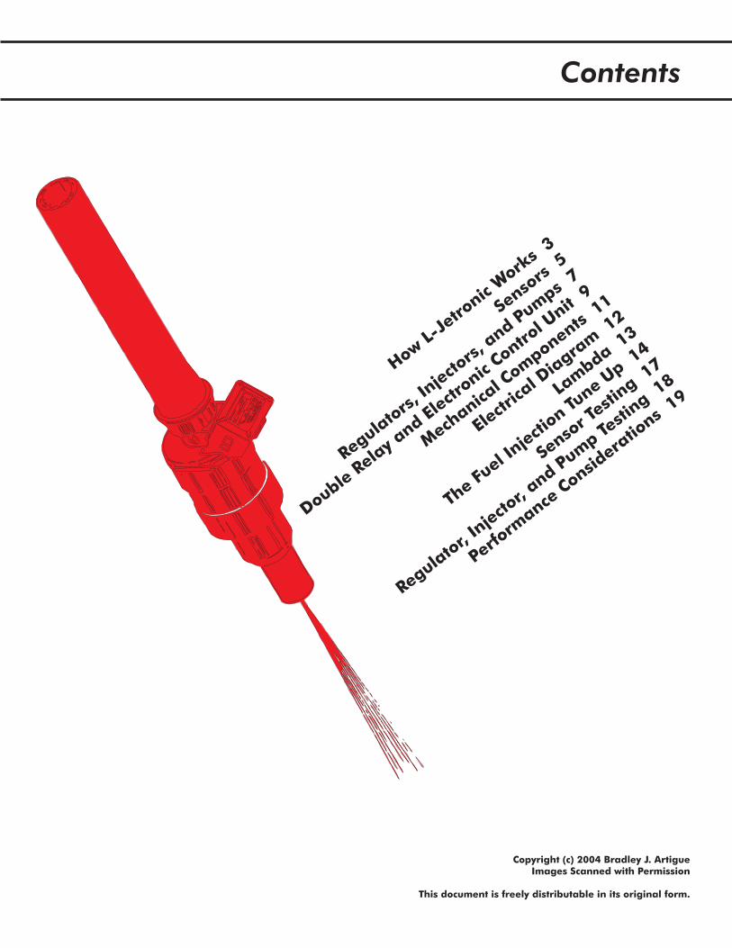
Contents
Copyright (c) 2004 Bradley J. ArtigueImages Scanned with Permission
This document is freely distributable in its original form.
In 1980 FIAT introduced a Bosch multiport fuel injection system in its vehicles. Introduced first onCalifornia-bound vehicles and, by 1981, on all U.S. vehicles, the Bosch system improved theperformance, efficiency, reliability, and quality of engine operations. Solely responsible for a 23horsepower increase on the 2 liter engines, this system, known as Bosch L-Jetronic, was popular not onlyon FIATs but on nearly every European car produced in the 1980's.
The L-Jetronic was the first mass-produced, fully electronic fuel injection system. Prior to L-Jetronic,mechanical fuel injection systems had proven that directly injecting atomized fuel into the cylinderresulted in better engine operation. Combining this direct injection theory with electronic sensors, valves,and meters - all controlled by a central computer - resulted in better operation than before.
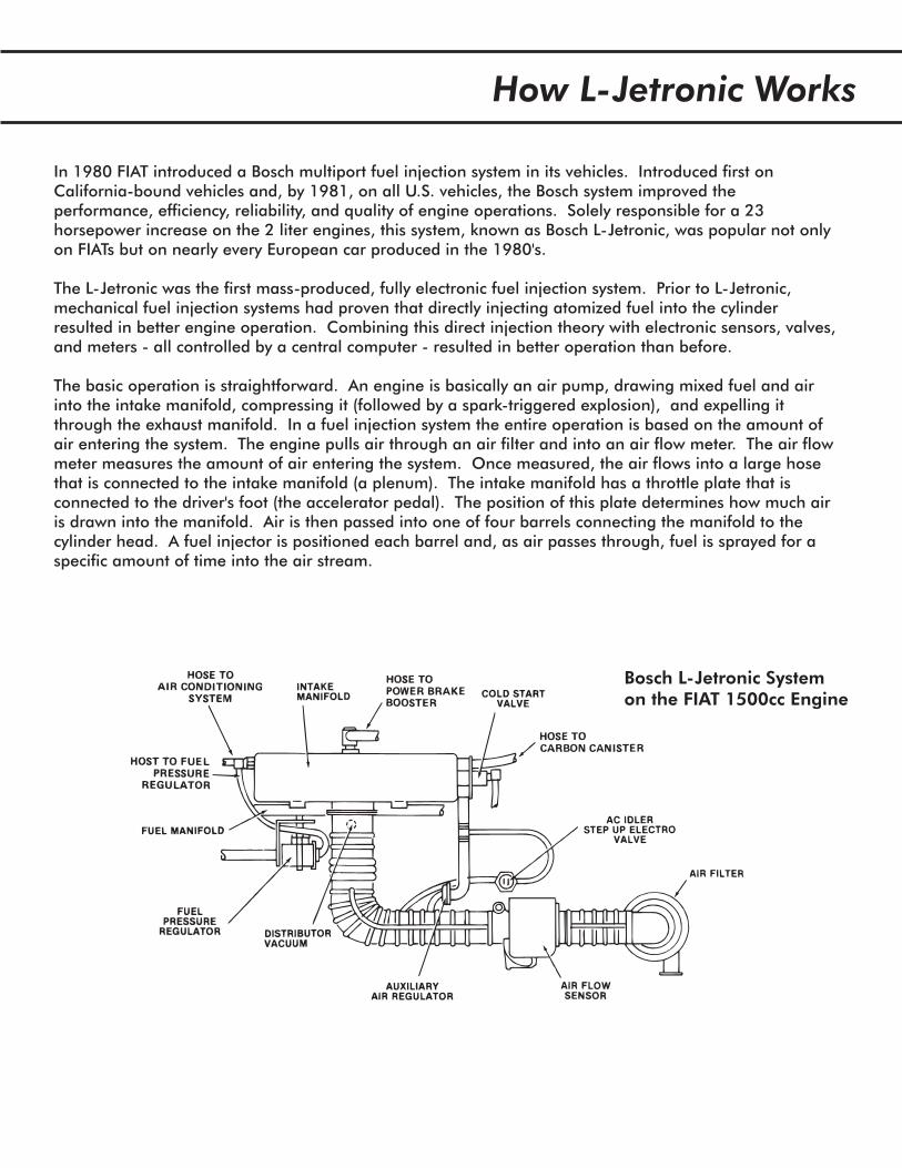
The basic operation is straightforward. An engine is basically an air pump, drawing mixed fuel and airinto the intake manifold, compressing it (followed by a spark-triggered explosion), and expelling itthrough the exhaust manifold. In a fuel injection system the entire operation is based on the amount ofair entering the system. The engine pulls air through an air filter and into an air flow meter. The air flowmeter measures the amount of air entering the system. Once measured, the air flows into a large hosethat is connected to the intake manifold (a plenum). The intake manifold has a throttle plate that isconnected to the driver's foot (the accelerator pedal). The position of this plate determines how much airis drawn into the manifold. Air is then passed into one of four barrels connecting the manifold to thecylinder head. A fuel injector is positioned each barrel and, as air passes through, fuel is sprayed for aspecific amount of time into the air stream.
Bosch L-Jetronic Systemon the FIAT 1500cc Engine
How L-Jetronic Works
This basic operation is achievable without an electronic fuel injection system. What an electronic systemoffers is precise control over fuel delivery and air flow. Utilizing sensors that determine air and enginetemperature, throttle position, exhaust gas content, and engine speed, an electronic system can preciselymeter the input of air and fuel. The result is a smooth, efficient engine.
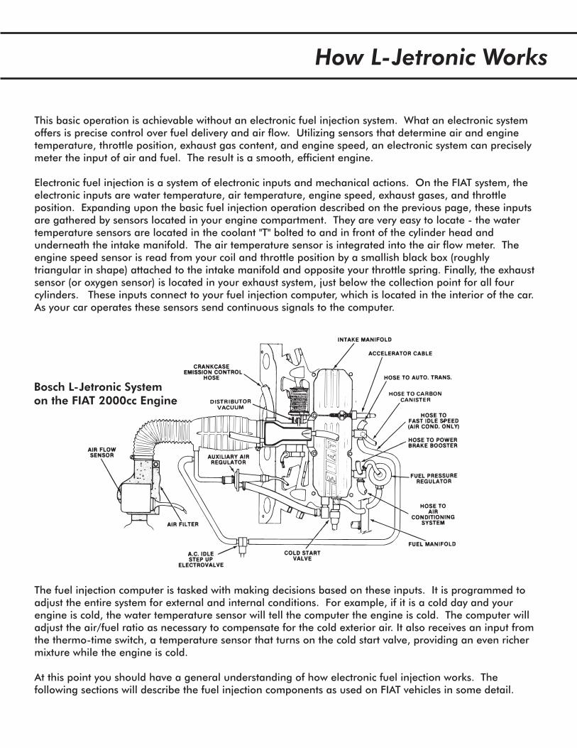
Electronic fuel injection is a system of electronic inputs and mechanical actions. On the FIAT system, theelectronic inputs are water temperature, air temperature, engine speed, exhaust gases, and throttleposition. Expanding upon the basic fuel injection operation described on the previous page, these inputsare gathered by sensors located in your engine compartment. They are very easy to locate - the watertemperature sensors are located in the coolant "T" bolted to and in front of the cylinder head andunderneath the intake manifold. The air temperature sensor is integrated into the air flow meter. Theengine speed sensor is read from your coil and throttle position by a smallish black box (roughlytriangular in shape) attached to the intake manifold and opposite your throttle spring. Finally, the exhaustsensor (or oxygen sensor) is located in your exhaust system, just below the collection point for all fourcylinders. These inputs connect to your fuel injection computer, which is located in the interior of the car.As your car operates these sensors send continuous signals to the computer.
The fuel injection computer is tasked with making decisions based on these inputs. It is programmed toadjust the entire system for external and internal conditions. For example, if it is a cold day and yourengine is cold, the water temperature sensor will tell the computer the engine is cold. The computer willadjust the air/fuel ratio as necessary to compensate for the cold exterior air. It also receives an input fromthe thermo-time switch, a temperature sensor that turns on the cold start valve, providing an even richermixture while the engine is cold.
At this point you should have a general understanding of how electronic fuel injection works. Thefollowing sections will describe the fuel injection components as used on FIAT vehicles in some detail.
Bosch L-Jetronic Systemon the FIAT 2000cc Engine
How L-Jetronic Works
The Bosch L-Jetronic system has a variety of sensors designed to signal the ECU (electronic control unit)throughout engine operation. There are two water temperature sensors, one throttle position sensor, oneexhaust sensor, and one air flow meter that all signal the ECU and must be operating correctly in orderfor your fuel injection system to remain efficient.
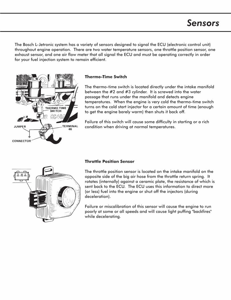
Thermo-Time Switch
The thermo-time switch is located directly under the intake manifoldbetween the #2 and #3 cylinder. It is screwed into the waterpassage that runs under the manifold and detects enginetemperatures. When the engine is very cold the thermo-time switchturns on the cold start injector for a certain amount of time (enoughto get the engine barely warm) then shuts it back off.
Failure of this switch will cause some difficulty in starting or a richcondition when driving at normal temperatures.
Throttle Position Sensor
The throttle position sensor is located on the intake manifold on theopposite side of the big air hose from the throttle return spring. Itrotates (internally) against a ceramic plate, the resistance of which issent back to the ECU. The ECU uses this information to direct more(or less) fuel into the engine or shut off the injectors (duringdeceleration).
Failure or miscalibration of this sensor will cause the engine to runpoorly at some or all speeds and will cause light puffing "backfires"while decelerating.
Sensors
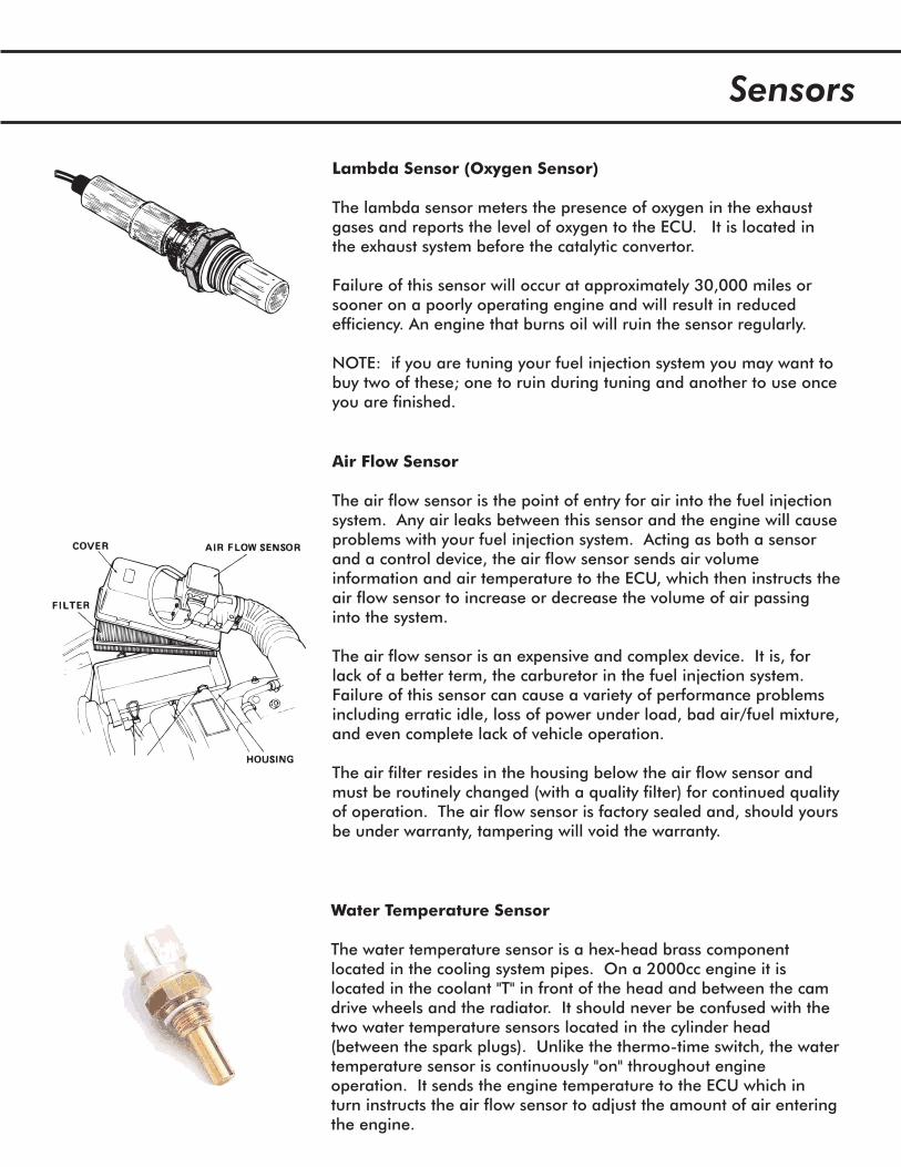
Air Flow Sensor
The air flow sensor is the point of entry for air into the fuel injectionsystem. Any air leaks between this sensor and the engine will causeproblems with your fuel injection system. Acting as both a sensorand a control device, the air flow sensor sends air volumeinformation and air temperature to the ECU, which then instructs theair flow sensor to increase or decrease the volume of air passinginto the system.
The air flow sensor is an expensive and complex device. It is, forlack of a better term, the carburetor in the fuel injection system.Failure of this sensor can cause a variety of performance problemsincluding erratic idle, loss of power under load, bad air/fuel mixture,and even complete lack of vehicle operation.
The air filter resides in the housing below the air flow sensor andmust be routinely changed (with a quality filter) for continued qualityof operation. The air flow sensor is factory sealed and, should yoursbe under warranty, tampering will void the warranty.
Lambda Sensor (Oxygen Sensor)
The lambda sensor meters the presence of oxygen in the exhaustgases and reports the level of oxygen to the ECU. It is located inthe exhaust system before the catalytic convertor.
Failure of this sensor will occur at approximately 30,000 miles orsooner on a poorly operating engine and will result in reducedefficiency. An engine that burns oil will ruin the sensor regularly.
NOTE: if you are tuning your fuel injection system you may want tobuy two of these; one to ruin during tuning and another to use onceyou are finished.
Water Temperature Sensor
The water temperature sensor is a hex-head brass componentlocated in the cooling system pipes. On a 2000cc engine it islocated in the coolant "T" in front of the head and between the camdrive wheels and the radiator. It should never be confused with thetwo water temperature sensors located in the cylinder head(between the spark plugs). Unlike the thermo-time switch, the watertemperature sensor is continuously "on" throughout engineoperation. It sends the engine temperature to the ECU which inturn instructs the air flow sensor to adjust the amount of air enteringthe engine.
Sensors
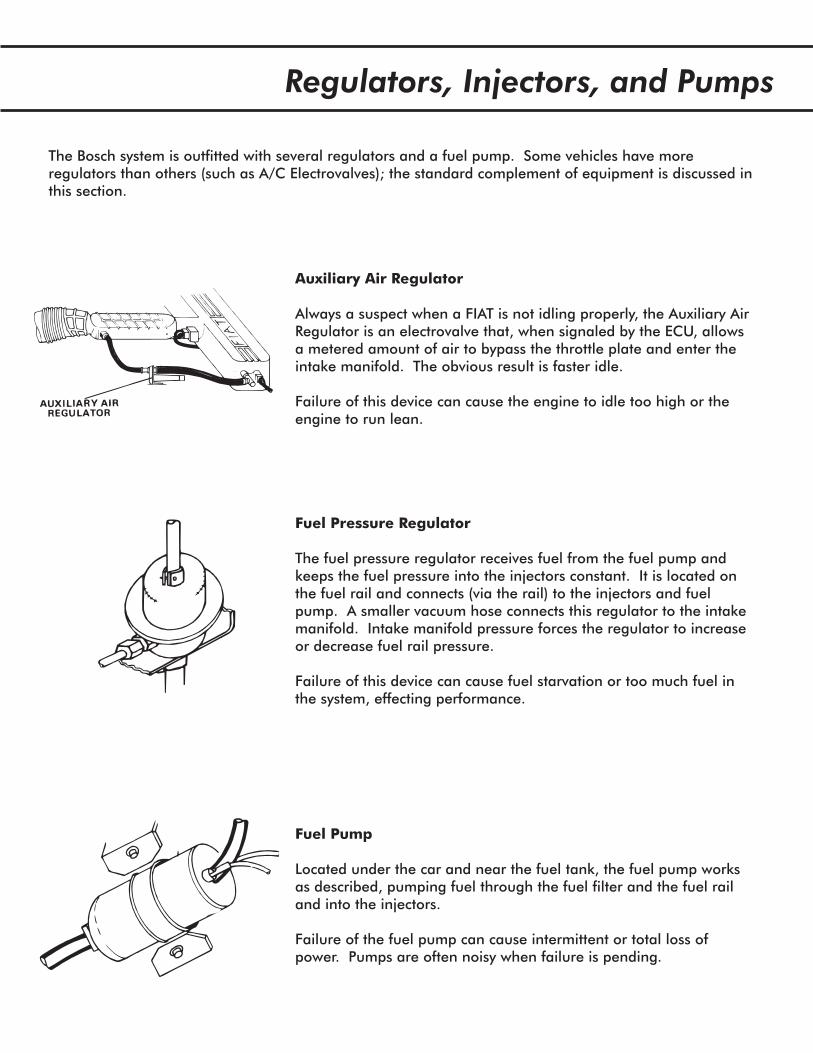
Auxiliary Air Regulator
Always a suspect when a FIAT is not idling properly, the Auxiliary AirRegulator is an electrovalve that, when signaled by the ECU, allowsa metered amount of air to bypass the throttle plate and enter theintake manifold. The obvious result is faster idle.
Failure of this device can cause the engine to idle too high or theengine to run lean.
Fuel Pressure Regulator
The fuel pressure regulator receives fuel from the fuel pump andkeeps the fuel pressure into the injectors constant. It is located onthe fuel rail and connects (via the rail) to the injectors and fuelpump. A smaller vacuum hose connects this regulator to the intakemanifold. Intake manifold pressure forces the regulator to increaseor decrease fuel rail pressure.
Failure of this device can cause fuel starvation or too much fuel inthe system, effecting performance.
Fuel Pump
Located under the car and near the fuel tank, the fuel pump worksas described, pumping fuel through the fuel filter and the fuel railand into the injectors.
Failure of the fuel pump can cause intermittent or total loss ofpower. Pumps are often noisy when failure is pending.
The Bosch system is outfitted with several regulators and a fuel pump. Some vehicles have moreregulators than others (such as A/C Electrovalves); the standard complement of equipment is discussed inthis section.
Regulators, Injectors, and Pumps
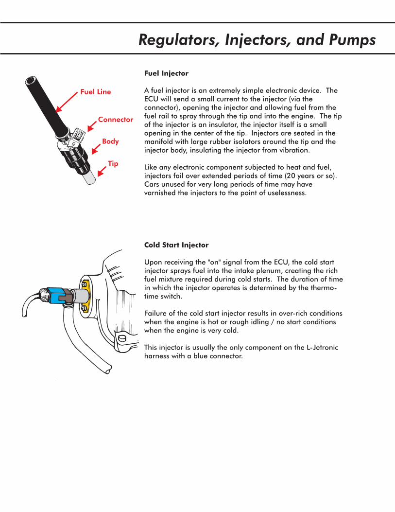
Connector
Fuel Line
Tip
Fuel Injector
A fuel injector is an extremely simple electronic device. TheECU will send a small current to the injector (via theconnector), opening the injector and allowing fuel from thefuel rail to spray through the tip and into the engine. The tipof the injector is an insulator, the injector itself is a smallopening in the center of the tip. Injectors are seated in themanifold with large rubber isolators around the tip and theinjector body, insulating the injector from vibration.
Like any electronic component subjected to heat and fuel,injectors fail over extended periods of time (20 years or so).Cars unused for very long periods of time may havevarnished the injectors to the point of uselessness.
Body
Cold Start Injector
Upon receiving the "on" signal from the ECU, the cold startinjector sprays fuel into the intake plenum, creating the richfuel mixture required during cold starts. The duration of timein which the injector operates is determined by the thermo-time switch.
Failure of the cold start injector results in over-rich conditionswhen the engine is hot or rough idling / no start conditionswhen the engine is very cold.
This injector is usually the only component on the L-Jetronicharness with a blue connector.
Regulators, Injectors, and Pumps
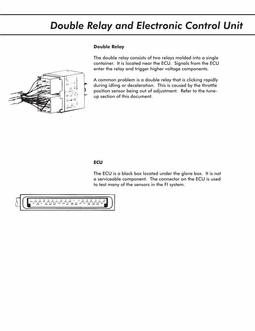
Double Relay and Electronic Control Unit
ECU
The ECU is a black box located under the glove box. It is nota serviceable component. The connector on the ECU is usedto test many of the sensors in the FI system.
Double Relay
The double relay consists of two relays molded into a singlecontainer. It is located near the ECU. Signals from the ECUenter the relay and trigger higher voltage components.
A common problem is a double relay that is clicking rapidlyduring idling or deceleration. This is caused by the throttleposition sensor being out of adjustment. Refer to the tune-up section of this document.
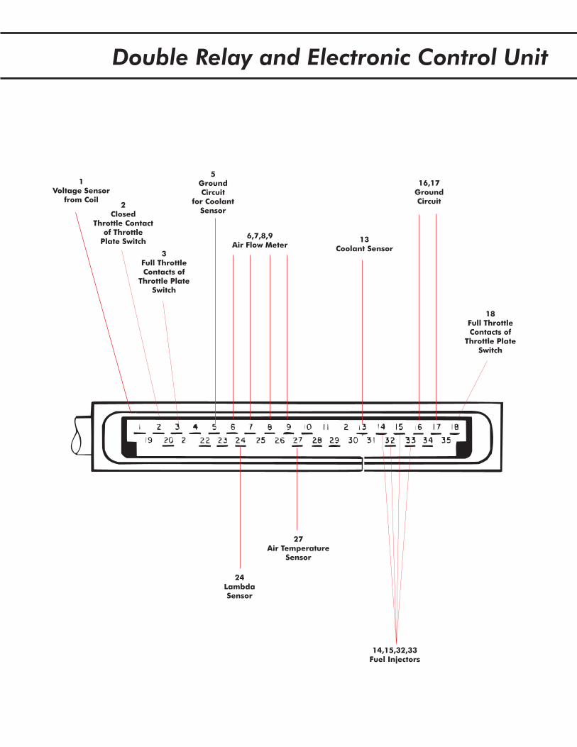
Double Relay and Electronic Control Unit
13Coolant Sensor
27Air Temperature
Sensor
24LambdaSensor
3Full ThrottleContacts of
Throttle PlateSwitch
18Full ThrottleContacts of
Throttle PlateSwitch
1Voltage Sensor
from Coil2
ClosedThrottle Contact
of ThrottlePlate Switch
5GroundCircuit
for CoolantSensor
16,17GroundCircuit
14,15,32,33Fuel Injectors
6,7,8,9Air Flow Meter
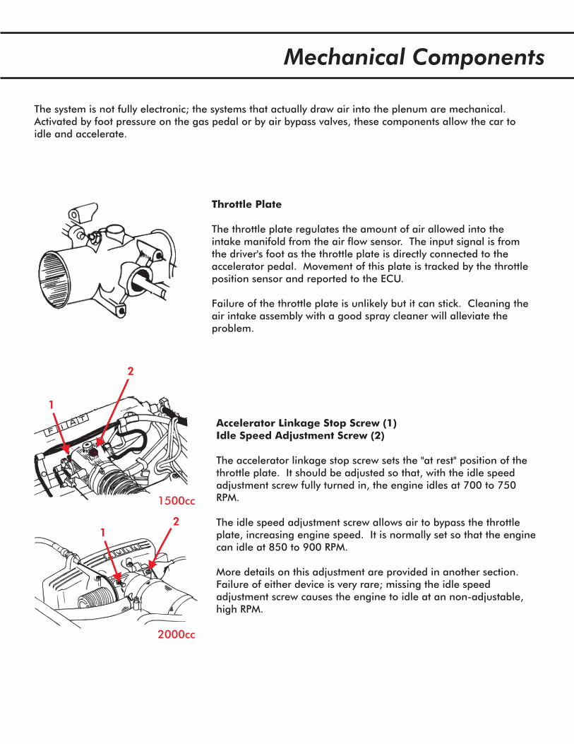
Throttle Plate
The throttle plate regulates the amount of air allowed into theintake manifold from the air flow sensor. The input signal is fromthe driver's foot as the throttle plate is directly connected to theaccelerator pedal. Movement of this plate is tracked by the throttleposition sensor and reported to the ECU.
Failure of the throttle plate is unlikely but it can stick. Cleaning theair intake assembly with a good spray cleaner will alleviate theproblem.
Accelerator Linkage Stop Screw (1)Idle Speed Adjustment Screw (2)
The accelerator linkage stop screw sets the "at rest" position of thethrottle plate. It should be adjusted so that, with the idle speedadjustment screw fully turned in, the engine idles at 700 to 750RPM.
The idle speed adjustment screw allows air to bypass the throttleplate, increasing engine speed. It is normally set so that the enginecan idle at 850 to 900 RPM.
More details on this adjustment are provided in another section.Failure of either device is very rare; missing the idle speedadjustment screw causes the engine to idle at an non-adjustable,high RPM.
1
2
1500cc
2000cc
12
The system is not fully electronic; the systems that actually draw air into the plenum are mechanical.Activated by foot pressure on the gas pedal or by air bypass valves, these components allow the car toidle and accelerate.
Mechanical Components
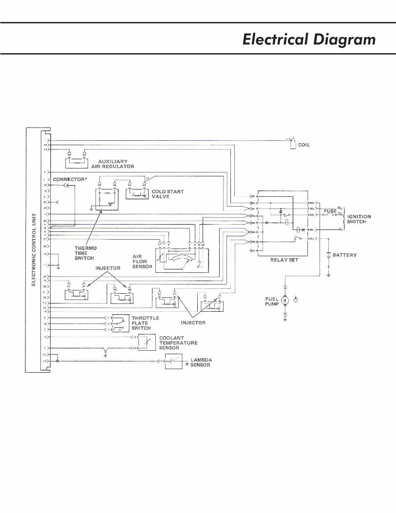
Electrical Diagram
Lambda
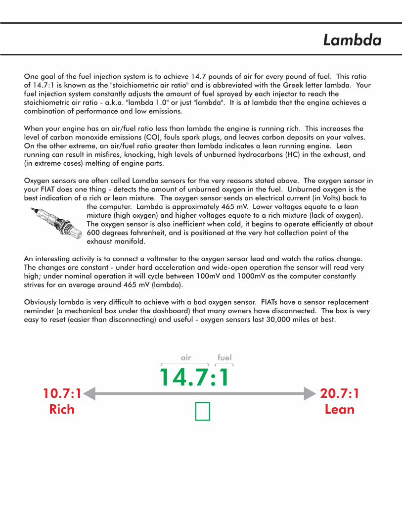
One goal of the fuel injection system is to achieve 14.7 pounds of air for every pound of fuel. This ratioof 14.7:1 is known as the "stoichiometric air ratio" and is abbreviated with the Greek letter lambda. Yourfuel injection system constantly adjusts the amount of fuel sprayed by each injector to reach thestoichiometric air ratio - a.k.a. "lambda 1.0" or just "lambda". It is at lambda that the engine achieves acombination of performance and low emissions.
When your engine has an air/fuel ratio less than lambda the engine is running rich. This increases thelevel of carbon monoxide emissions (CO), fouls spark plugs, and leaves carbon deposits on your valves.On the other extreme, an air/fuel ratio greater than lambda indicates a lean running engine. Leanrunning can result in misfires, knocking, high levels of unburned hydrocarbons (HC) in the exhaust, and(in extreme cases) melting of engine parts.
Oxygen sensors are often called Lamdba sensors for the very reasons stated above. The oxygen sensor inyour FIAT does one thing - detects the amount of unburned oxygen in the fuel. Unburned oxygen is thebest indication of a rich or lean mixture. The oxygen sensor sends an electrical current (in Volts) back to
the computer. Lambda is approximately 465 mV. Lower voltages equate to a leanmixture (high oxygen) and higher voltages equate to a rich mixture (lack of oxygen).The oxygen sensor is also inefficient when cold, it begins to operate efficiently at about600 degrees fahrenheit, and is positioned at the very hot collection point of theexhaust manifold.
An interesting activity is to connect a voltmeter to the oxygen sensor lead and watch the ratios change.The changes are constant - under hard acceleration and wide-open operation the sensor will read veryhigh; under nominal operation it will cycle between 100mV and 1000mV as the computer constantlystrives for an average around 465 mV (lambda).
Obviously lambda is very difficult to achieve with a bad oxygen sensor. FIATs have a sensor replacementreminder (a mechanical box under the dashboard) that many owners have disconnected. The box is veryeasy to reset (easier than disconnecting) and useful - oxygen sensors last 30,000 miles at best.
14.7:110.7:1 20.7:1Rich Lean
air fuel
�
The Fuel Injection Tune Up
Those of you who read my guide on carburetion, intake, and exhaust are familiar with my approach togetting the most out of your engine. The first step is understanding how it all works (which I hope theprevious sections of this guide explained). The second step is to get everything working exactly as it wasdesigned to. The third step is to tweak it - or not - and achieve what consider optimal performance.
Install new spark plugs and gap them appropriately. Get the correct plug for your engine (don'tget fancy here and don't waste money on platinum plugs until after the car is set up).
Most FIAT owners I've spoken with are looking for optimal performance in their car. Regardless of howperformance is defined, many owners share perception that their Spider (or Brava, X1/9, or whatever) isperforming under its capability and - this is the important part- that the car never really had greatperformance to begin with. Let's take the latter statement first - it is flat out wrong. Anyone who hasdriven a new or properly tuned FIAT knows that the fuel injected engines performed quite well. Theformer statement - the one about the vehicle's capability - is a relative term. For example, a tired enginewon't perform very well regardless of how well it is tuned.
To further confuse you I'll leave you with a final thought before delving into how to get your engine tunedup. That is: you have no idea if your engine is under performing if your engine is not set up properly. Ifyou've decided that you like 15 degrees advance at TDC then you're not set up properly. If you'vedecided to disconnect the oxygen sensor because "that's emissions control equipment" (I love that, by theway, because it's so wrong) then your not set up properly. If your vacuum advance diaphragm is simply agateway for air entering the intake manifold, you're not set up properly. Getting the picture here?
The goal of this section is to get your fuel injection system and engine set to the proper specifications sothat you can judge what is really wrong and what to start tweaking. I may as well say it now - beprepared to spend some amount of money on sensors, fuel injectors, air and fuel hose, a gasket or two,distributor parts, and spark plugs. Hopefully no one ever told you that working on cars was free orcheap!
Checklist for your tune up:
1. Change the oil with the correct grade for your climate zone. This usually results in 15W40,20W50, or 10W40. Check your owner's manual.
2. Flush the cooling system and refill it properly.
3. Replace the air cleaner filter (the maintenance interval is 30,000 miles but FIAT recommends15,000 miles).
4.Install new
spark plug wires if necessary. Brittle or cheap wires can arc, causing the fuel injection system to haveall kinds of bad electrical interference and loads of bad spark.
5. Install a new distributor cap, rotor, pickup, and vacuum advance diaphragm if necessary. The firstthree are standard tune-up parts; the advance diaphragm is important because your car just won'taccelerate correctly if it is bad. To diagnose it, start the engine and look down at the diaphragm's rod.Have someone tap the gas - the rod should move (advancing the distributor). If it does not, replace it.
6. How old is your oxygen sensor? Don't know? Replace it.
7. Set the engine timing to the exact spot appropriate for your model year. On most FIATs this is 10degrees BTDC.
The Fuel Injection Tune Up
1. Check the valve lash and adjust as necessary.
2. Start the car and warm the engine.
3. Once the engine is warm, note how it sounds and operates.
4. Set the idle speed according to the factory procedure.
Out of spec valve lash can make an engine run rough and noisy. Check the valve lash, adjust it, andreplace the cam cover gaskets if necessary. On the fuel injected Spider you may have to remove theintake plenum lid to get the intake side cam cover off the car. If you do, replace the plenum gasket aswell and clean out the plenum with carburetor cleaner.
Note: a plenum full of fuel varnish is getting fuel sprayed back into it. In other words, something isor was wrong with the operation of the engine. Engines suck air from the plenum, not into it.
In order to properly tune the system you must operate the engine at 190 degrees. In FIAT terms thismeans start the car and let it run through two fan cycles. If your engine does not run then you mightwant to work through the troubleshooting section of this guide before you try and tune the engine.
This isn't lambda zen or something like that. Make notes on the idle RPM, engine misfires, the smellof gas, the sound of leaking air, clacking of valves, etc. This is your opportunity to identify what youmay need to address as you work through these procedures.
The procedure is:
A. Run the engine to normal operating temperature (step 2above).
B. On cars with automatic transmissions, set the parkingbrake, block the wheels, and put the transmission in "D".
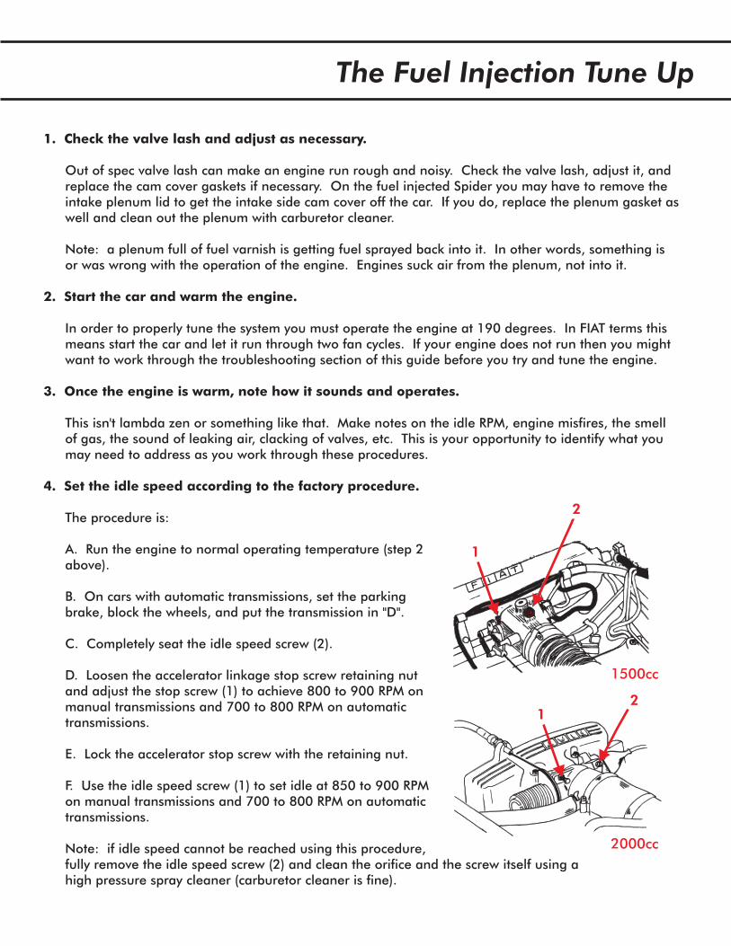
C. Completely seat the idle speed screw (2).
D. Loosen the accelerator linkage stop screw retaining nutand adjust the stop screw (1) to achieve 800 to 900 RPM onmanual transmissions and 700 to 800 RPM on automatictransmissions.
E. Lock the accelerator stop screw with the retaining nut.
F. Use the idle speed screw (1) to set idle at 850 to 900 RPMon manual transmissions and 700 to 800 RPM on automatictransmissions.
Note: if idle speed cannot be reached using this procedure,fully remove the idle speed screw (2) and clean the orifice and the screw itself using ahigh pressure spray cleaner (carburetor cleaner is fine).
1
2
1500cc
2000cc
12
The Fuel Injection Tune Up
5. Throttle Position Sensor Adjustment
6. Test the vehicle and determine what to do next.
Tuned up?
The throttle position sensor tells the ECU to turn off the injectors during deceleration. It also tells theECU when the throttle is fully open, allowing the full flow of the injectors.
A. Unplug the throttle plate switch. Note the connector blades (on the plate switch, not the connectoritself) are marked 3 18 and 2 .
B. Connect an ohmmeter between terminals 2 and 18 of the switch.
C. Loosen the two screws holding the switch in place.
D. Rotate the switch clockwise until the ohmmeter indicates a closed circuit.
E. Tighten the two screws.
F. Reconnect the switch.
A. Run the engine and drive the car. Note irregularities (puffs, misses, smells, etc.). Stop the engineand pull the spark plugs.
B. Considerations for moving forward:
- Missing and puffing: Check all of the air hoses for tightness and leaks. Any suspect hosesshould be replaced. Air leaks are a primary cause of poor performance in fuel injected systems.
- Fuel smell: check the hoses leading from the fuel rail into the injectors and to and from the fueltank and cold start injector. Hoses are 7.5mm - - and can be purchased at AlfaRomeo, BMW, VW, and Porsche dealers. Also replace both seals!
- Black plugs? Check the ignition timing and ignition components and be sure the throttle plate isopening fully. Other causes are leaky injectors, a bad cold start valve, a bad air flow sensor, or aa bad coolant temperature sensor resistance. Refer to the next section.
- White plugs? How white? L-jetronic systems typically run slightly lean and plugs have a whitish-brown color. An air leak is the most common cause or the failure of one of the FI sensors. Airleaks can occur in the injector seals as well - if you are unsure of the age it may be worthwhile toreplace the seals. Refer to the next section and check the sensors for proper operation.
If your vehicle is performing well and your spark plugs are whitish-brown then you are probably welltuned. The fuel injection system results in smooth acceleration and deceleration without puffs or pops. Inthe next section we ll look at how to test your sensors to make sure they are all working well.
NOT 8mm
Sensor Testing
Coolant Temperature Sensor Resistance
Thermo Time Switch
Cold Start Valve
Air Flow Sensor
Oxygen Sensor
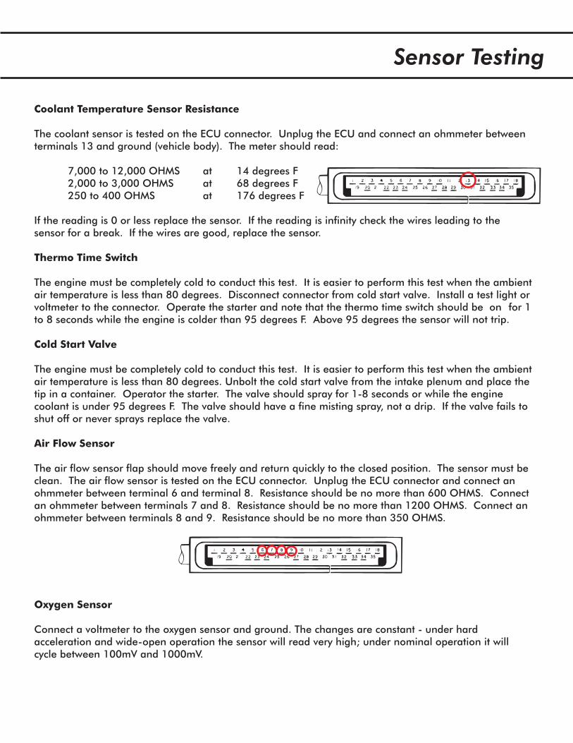
The coolant sensor is tested on the ECU connector. Unplug the ECU and connect an ohmmeter betweenterminals 13 and ground (vehicle body). The meter should read:
7,000 to 12,000 OHMS at 14 degrees F2,000 to 3,000 OHMS at 68 degrees F250 to 400 OHMS at 176 degrees F
If the reading is 0 or less replace the sensor. If the reading is infinity check the wires leading to thesensor for a break. If the wires are good, replace the sensor.
The engine must be completely cold to conduct this test. It is easier to perform this test when the ambientair temperature is less than 80 degrees. Disconnect connector from cold start valve. Install a test light orvoltmeter to the connector. Operate the starter and note that the thermo time switch should be on for 1to 8 seconds while the engine is colder than 95 degrees F. Above 95 degrees the sensor will not trip.
The engine must be completely cold to conduct this test. It is easier to perform this test when the ambientair temperature is less than 80 degrees. Unbolt the cold start valve from the intake plenum and place thetip in a container. Operator the starter. The valve should spray for 1-8 seconds or while the enginecoolant is under 95 degrees F. The valve should have a fine misting spray, not a drip. If the valve fails toshut off or never sprays replace the valve.
The air flow sensor flap should move freely and return quickly to the closed position. The sensor must beclean. The air flow sensor is tested on the ECU connector. Unplug the ECU connector and connect anohmmeter between terminal 6 and terminal 8. Resistance should be no more than 600 OHMS. Connectan ohmmeter between terminals 7 and 8. Resistance should be no more than 1200 OHMS. Connect anohmmeter between terminals 8 and 9. Resistance should be no more than 350 OHMS.
Connect a voltmeter to the oxygen sensor and ground. The changes are constant - under hardacceleration and wide-open operation the sensor will read very high; under nominal operation it willcycle between 100mV and 1000mV.
Regulator, Injector, and Pump Testing
Auxiliary Air Regulator
Fuel Pump and Pressure Regulator
Injector Fuel Delivery
Injector Voltage
The auxiliary air regulator voltage can be tested by connecting a test light or volt meter to the connectorpoles. Voltage will be apparent when the engine is running. If voltage is not apparent replace thedouble relay.
The air regulator may be suspect if the vehicle is idling poorly and all idle-related tests have beencompleted successfully. The regulator hose can be pinched off for testing. When off the regulator willnot allow air to pass through it.
The fuel pump should never be noisy. Voltage at the pump terminals should be approximately 12V;terminals are prone to getting dirty and cleaning them may improve connectivity. Terminals should haverubber boots over them; if not, consider covering connections with electrical tape or silicone.
Fuel pump operation can be tested by opening the fuel system in the engine compartment. You shouldconsult a factory shop manual for this procedure. Fuel feed pressure is 36 +/- 3 psi with the fuelpressure regulator disconnected. Pressure is 28 psi with the regulator connected.
Injectors can be tested by removing the injector and placing the nozzle in a glass container. Operate theengine and check that the fuel spray is a mist. There should be no drips. Injectors pulse during normaloperation (see the injector voltage test).
You can test the injector voltage pulse with a voltmeter or test light. Disconnect an injector plug andconnect to each plug in the connector. Operate the starter (the car may or may not start) and note thatvoltage should pulse - making the light flicker weakly or the voltage to fluctuate. If there is no fluctuationthen the ECU may be bad.
Performance Considerations
The L-Jetronic system is not highly customizable. As a rule, modifications to the combustioncharacteristics of the engine (such as radical camshaft modifications) create difficulties with the system.However, some modifications do improve performance.
There is little that can be done to the air flow meter to improve performance. The meter has a flap that istensioned by a spring. The spring tension is set by a geared wheel held in place by a metal rod. Bymanipulating the geared wheel and tightening the tension one can fool the ECU into a slightly richercondition. If you are considering this modification keep these things in mind: 1) A minor change is allthat is required. Radical shifts in the spring tension result in over-rich conditions. 2) Mark the originalposition of the spring before moving the wheel. 3) This will void the AFM warranty.
My favorite fuel injected Spider had all standard engine components except for the pistons. I installed aset of 8.9:1 CR Kolbenschmidt pistons and was impressed at two things. First, there was no effect on thefuel injection system s operation. The car still ran smooth, passed emissions, and had good fueleconomy. Second, the performance was dramatically improved. Acceleration was wonderful andresponse was much better than the stock 8.1:1 pistons.
My second favorite fuel injected Spider had the 8.1:1 pistons but an 1800cc cylinder head with stockvalves. The head was surfaced slightly (enough to get some minor dings off the mating surface). Like thepiston swap mentioned above the acceleration was much better. The 1800cc head is not as efficient atspeed; therefore the overall experience at speed was the same as a stock car.
By lightening engine components - namely the cam shaft pulleys, flywheel and clutch, and connectingrods - the engine can wind up faster and respond to changes quickly. This offers a great performanceboost across all areas of engine components and does not affect the fuel injection system.
I have had limited success implementing cams more radical than 40/80 in a fuel injected engine. Franklythe mild performance change from stock to 40/80 wasn t worth the cost of the cams. The 40/80 did notaffect the fuel injection system except that fuel economy dropped slightly.
I do not profess that 10 degrees BTDC is the right timing for your engine. In fact I doubt that the timingindicator on your 20+ year old car is actually at 10 degrees BTDC and is probably off by a few degrees. Ilike to set an engine timing by ear. I find that the correct tuning is the point where the engine runs fastestwithout any puffs during operation. On one of my cars this resulted in 13 degrees BTDC, in another itresulted in 8 degrees BTDC. Different engines, different heads, different timing.
The engine with the Kolbenschmidts (mentioned above) also had a Marelliplex, a rather rare mechanicaladvance replacement for the electronic distributor. I noted no difference in quality of operation.
Air Flow Meter Modifications
Compression Increases
Light Components
Camshaft Changes
Ignition Timing
Marelliplex and Mechanical Advance Distributors


![Информация о Product Information ESI[tronic] 2.0 Off Highway - Bosch … · 2019. 6. 20. · BAE SYSTEMS, BOSCH REXROTH, CASE CONSTRUCTION, CATERPILLAR, FIAT KOBELCO, GROVE,](https://static.fdocuments.net/doc/165x107/60bf308697d2a66b07450eb8/-product-information-esitronic-20-off-highway-bosch.jpg)