
A Geosynchronous Imaging Fourie r Transform Spectrometer ...
12
A Geosynchronous Imaging Fourier Transform Spectrometer (GIFTS) for Hyperspectral Atmospheric Remote Sensing: Instrument Overview & Preliminary Performance Results J.D. Elwell 1 , G.W. Cantwell 1 , D.K. Scott 1 , R.W. Esplin 1 , G.B. Hansen 1 , S.M. Jensen 1 , M.D. Jensen 1 , S.B. Brown 1 , L.J. Zollinger 1 , V.A. Thurgood 1 , M.P. Esplin 1 , R.J. Huppi 2 , G.E. Bingham 1 , H.E. Revercomb 3 , F.A. Best 3 , D.C. Tobin 3 , J.K. Taylor 3 , R.O. Knuteson 3 , W.L. Smith 4 , R.A. Reisse 5 , and R. Hooker 6 1 Space Dynamics Laboratory, Utah State University, Logan, UT; 2 ZEL Technologies, LLC, Hampton, VA 3 Space Science & Engineering Center, Univ. of Wisconsin, Madison, WI; 4 Center for Atmospheric Sciences, HU, Hampton, VA 5 NASA Langley Research Center, Hampton, VA 6 NASA Headquarters, Washington, DC ABSTRACT The Geosynchronous Imaging Fourier Transform Spectrometer (GIFTS) was developed for the NASA New Millennium Program (NMP) Earth Observing-3 (EO-3) mission. This paper discusses the GIFTS measurement requirements and the technology utilized by the GIFTS sensor to provide the required system performance. Also presented are preliminary results from the recently completed calibration of the instrument. The GIFTS NMP mission challenge was to demonstrate new and emerging sensor and data processing technologies to make revolutionary improvements in meteorological observational capability and forecasting accuracy using atmospheric imaging and hyperspectral sounding methods. The GIFTS sensor is an imaging FTS with programmable spectral resolution and spatial scene selection, allowing radiometric accuracy and atmospheric sounding precision to be traded in near-real time for area coverage. System sensitivity is achieved through the use of a cryogenic Michelson interferometer and two large-area, IR focal plane detector arrays. Due to funding limitations, the GIFTS sensor module was completed as an engineering demonstration unit, which can be upgraded for flight qualification. Capability to meet the next generation geosynchronous sounding requirements has been successfully demonstrated through thermal vacuum testing and rigorous IR calibration activities. Keywords: Geosynchronous, Fourier transform spectrometer (FTS), Michelson interferometer, hyperspectral, climate 1. INTRODUCTION Efforts to increase the spectral and spatial resolution of satellite based atmospheric sounding instruments began more than twenty-five years ago when it became obvious that the spectral resolution limitations of filter based instruments limited profile recovery accuracy and resolution. For example, the United States has launched the Advanced InfraRed Sounder (AIRS), which is providing high resolution infrared data aboard the EOS Aqua platform (http://aqua.gsfc.nasa.gov/), with similar capability provided for trace gases by the TES sensor (http://aura.gsfc.nasa.gov/tes/). Operationally, the NPOESS series satellites will carry the Crosstrack Infrared Sounder (CrIS), which will use a Michelson interferometer to provide AIRS quality data in a much smaller and less expensive package. Similar advances are being developed by other countries to replace their research and operational sensors. These sensors build on previous applications of interferometers in aircraft and space applications 1-7 . The Geosynchronous Imaging Fourier Transform Spectrometer (GIFTS), built by the Space Dynamics Laboratory of Utah State University, was a NASA New Millennium Program (NMP) sponsored instrument designed to validate the technologies required to provide at least an order of magnitude improvement in the next generation measurement Infrared Spaceborne Remote Sensing XIV, edited by Marija Strojnik, Proc. of SPIE Vol. 6297, 62970S, (2006) · 0277-786X/06/$15 · doi: 10.1117/12.684135 Proc. of SPIE Vol. 6297 62970S-1 Downloaded from SPIE Digital Library on 03 Oct 2011 to 128.104.110.39. Terms of Use: http://spiedl.org/terms
Transcript of A Geosynchronous Imaging Fourie r Transform Spectrometer ...

A Geosynchronous Imaging Fourier Transform Spectrometer (GIFTS) for Hyperspectral Atmospheric Remote Sensing: Instrument Overview
& Preliminary Performance Results
J.D. Elwell1, G.W. Cantwell1, D.K. Scott1, R.W. Esplin1, G.B. Hansen1, S.M. Jensen1, M.D. Jensen1, S.B. Brown1, L.J. Zollinger1, V.A. Thurgood1, M.P. Esplin1, R.J. Huppi2, G.E. Bingham1, H.E.
Revercomb3, F.A. Best3, D.C. Tobin3, J.K. Taylor3, R.O. Knuteson3, W.L. Smith4, R.A. Reisse5, and R. Hooker6
1Space Dynamics Laboratory, Utah State University, Logan, UT; 2ZEL Technologies, LLC, Hampton, VA
3Space Science & Engineering Center, Univ. of Wisconsin, Madison, WI; 4Center for Atmospheric Sciences, HU, Hampton, VA
5NASA Langley Research Center, Hampton, VA 6NASA Headquarters, Washington, DC
ABSTRACT
The Geosynchronous Imaging Fourier Transform Spectrometer (GIFTS) was developed for the NASA New Millennium Program (NMP) Earth Observing-3 (EO-3) mission. This paper discusses the GIFTS measurement requirements and the technology utilized by the GIFTS sensor to provide the required system performance. Also presented are preliminary results from the recently completed calibration of the instrument. The GIFTS NMP mission challenge was to demonstrate new and emerging sensor and data processing technologies to make revolutionary improvements in meteorological observational capability and forecasting accuracy using atmospheric imaging and hyperspectral sounding methods. The GIFTS sensor is an imaging FTS with programmable spectral resolution and spatial scene selection, allowing radiometric accuracy and atmospheric sounding precision to be traded in near-real time for area coverage. System sensitivity is achieved through the use of a cryogenic Michelson interferometer and two large-area, IR focal plane detector arrays. Due to funding limitations, the GIFTS sensor module was completed as an engineering demonstration unit, which can be upgraded for flight qualification. Capability to meet the next generation geosynchronous sounding requirements has been successfully demonstrated through thermal vacuum testing and rigorous IR calibration activities.
Keywords: Geosynchronous, Fourier transform spectrometer (FTS), Michelson interferometer, hyperspectral, climate
1. INTRODUCTION Efforts to increase the spectral and spatial resolution of satellite based atmospheric sounding instruments began more than twenty-five years ago when it became obvious that the spectral resolution limitations of filter based instruments limited profile recovery accuracy and resolution. For example, the United States has launched the Advanced InfraRed Sounder (AIRS), which is providing high resolution infrared data aboard the EOS Aqua platform (http://aqua.gsfc.nasa.gov/), with similar capability provided for trace gases by the TES sensor (http://aura.gsfc.nasa.gov/tes/). Operationally, the NPOESS series satellites will carry the Crosstrack Infrared Sounder (CrIS), which will use a Michelson interferometer to provide AIRS quality data in a much smaller and less expensive package. Similar advances are being developed by other countries to replace their research and operational sensors. These sensors build on previous applications of interferometers in aircraft and space applications1-7.
The Geosynchronous Imaging Fourier Transform Spectrometer (GIFTS), built by the Space Dynamics Laboratory of Utah State University, was a NASA New Millennium Program (NMP) sponsored instrument designed to validate the technologies required to provide at least an order of magnitude improvement in the next generation measurement
Infrared Spaceborne Remote Sensing XIV, edited by Marija Strojnik, Proc. of SPIEVol. 6297, 62970S, (2006) · 0277-786X/06/$15 · doi: 10.1117/12.684135
Proc. of SPIE Vol. 6297 62970S-1
Downloaded from SPIE Digital Library on 03 Oct 2011 to 128.104.110.39. Terms of Use: http://spiedl.org/terms

capabilities from geosynchronous orbit. NMP was managed by NASA’s Jet Propulsion Laboratory, and the GIFTS project was managed by the NASA Langley Research Center (LaRC). GIFTS is a revolutionary new instrument, capable of providing from geosynchronous orbit the high spatial density temperature, moisture and trace gas profiles with the high vertical and temporal resolution typical of low Earth orbit sensors. GIFTS implements the atmospheric remote sensing desires that were explored earlier in the GHIS8 program, but provides the vast improvements in spatial coverage and sensitivity achievable using the parallel spatial measurement advantages of an imaging interferometer.
The GIFTS sensor was originally intended to fly on NASA’s Earth Observing-3 geosynchronous satellite in a mission jointly sponsored by NASA, NOAA, the US Navy and Air Force. However, funding limitations forced the program to terminate flight qualification activities and to complete the instrument as an engineering demonstration unit (EDU). The GIFTS EDU was completed and thermal-vacuum tested and characterized using prototype electronics and some other components. This paper provides an overview of the as-built GIFTS EDU and summarizes the sensor’s performance.
The GIFTS design achieves the mass and performance technology advances by combining several technologies. Large-area (128 x 128 pixel) format focal plane arrays (FPAs) enable frequent high spatial resolution coverage over large areas, while the Fourier Transform Spectrometer (FTS) provides simultaneous high spectral resolution. The imaging interferometer concept is not new. A patent on the idea was awarded to A.E Potter in 19729. A fieldable system was developed by SDL and utilized to collect upper atmosphere data from balloons in the mid through late 1970s10. With the advent of large area FPAs and high capacity electronics and microprocessors, SDL expanded the concept from the 4x4 detector system used in the 1970s into the GIFTS design. Other spectral imaging systems utilizing FPA detectors have been published previously11, 12.
The fundamental advantage of the GIFTS concept is demonstrated by the spectral images shown in Figure 1. During thermal-vacuum testing of the GIFTS EDU the instrument was configured to view down-welling radiance of the sky and Moon. The images in Figure 1 are all from a single data cube collected in ~11 seconds. Figure 1a shows the moon in the visible spectrum, as collected by the visible imager. Figures 1b and 1c show spectral slices at 9.2 cm-1 resolution in transparent and opaque regions of the atmosphere, respectively. Figure 1d shows the full long-wave (LWIR) and short/mid-wave (SMWIR) spectrum at 0.57 cm-1 resolution for two different pixels in the image, one viewing the moon, and one viewing clear sky. The test configuration for collection of the data shown in Figure 1 included a 12-meter horizontal path through warm atmosphere, which explains the detailed line structure in the opaque region of the 6.3 micron water vapor region, as well as emissions from a ZnSe window and a 45-degree turning mirror. The figure illustrates the power of the GIFTS concept: high-resolution spectral information at each spatial location in the image.
1.1. Measurement objectives
The GIFTS measurement concept can improve temperature, water vapor and trace gas sounding and IR imaging from geosynchronous orbit in several areas: faster area coverage, higher spatial and spectral resolution, with lower mass and volume. Sensing the atmosphere of the Earth disk at high spatial resolution requires a high data collection rate. An advantage of the GIFTS Michelson interferometer is the ability to trade off spectral resolution for coverage area to support varying requirements, as summarized in Table 1. GIFTS resolution can be programmed on a scan by scan basis in powers of 2.
Table 1. Example GIFTS spectral resolutions and their associated area coverage rates.
Resolution Coverage Mode
Spectral OPD Area Time*
Collection Modes 0.57-36 cm-1 0.014-0.872 cm 512 km sq. 1 to 11 sec
Regional Imaging 36 cm-1 0.014 cm 6,000 km sq. 3 min
Global Sounding 18 cm-1 0.027 cm 10,000 km sq. 7 min
Regional Sounding and Chemistry 0.57 cm-1 0.872 cm 6,000 km sq. 25 min
Self Validation** 0.57 cm-1 0.872 cm 10,000 km sq. 60 min
*Assumes a constant data rate associated with a Michelson mirror scan velocity of 0.17 cm/sec and 1-second telescope pointing step time. **Provides radiometric precision better than 0.1K over all wavelengths
Proc. of SPIE Vol. 6297 62970S-2
Downloaded from SPIE Digital Library on 03 Oct 2011 to 128.104.110.39. Terms of Use: http://spiedl.org/terms

1sIbIe Uncalibrats Image
IJIb.SSpE,.I
L.Iib..0d 104132
Fig. 1. Results from a single interferometer scan of the moon, viewed in the visible, mid-wave IR, and long-wave IR. Also the spectral intensities of two selected pixels from the IR images, one viewing the moon, the other the clear sky background.
1.2. GIFTS wind profile measurement concept
In addition to providing state-of-the-science temperature, water vapor, and trace gas soundings, GIFTS was designed to allow further processing of the data to provide wind profiles. It has been demonstrated by model simulation and aircraft based instruments7 that clear air vertical profiles of wind velocity can be achieved by tracking the movement of small-scale, non- condensed moisture features observed as a function of altitude. This measurement cannot be made by low Earth orbit observational satellites. Viewing from a geosynchronous satellite, the instrument can repeatedly sample regions of convective instability to develop fine scale image motion displacements and derive the wind profile. GIFTS’s high spectral and spatial resolution capability supports this goal. The high spectral resolution (0.57 cm-1) measurement mode provides infrared radiance over a large area (512 x 512 km) of the Earth at 11-second intervals. A visible-band camera is included in the system to provide cloud images at 1-km spatial resolution for each IR view. Extended Earth coverage is achieved by stepping the instrument FOV across the desired area of the Earth. The radiance measured at each time step are transformed to high vertical resolution (1-2 km) temperature and water vapor mixing ratio profiles using profile retrieval algorithms similar to those proven by AIRS. These profiles are obtained on a 4-km grid and then converted to relative humidity profiles to track moisture movement. Details of the GIFTS mission concept are provided by Smith13.
a.
b.
c. d.
Proc. of SPIE Vol. 6297 62970S-3
Downloaded from SPIE Digital Library on 03 Oct 2011 to 128.104.110.39. Terms of Use: http://spiedl.org/terms

2. GIFTS SENSOR DESIGN The GIFTS sensor was completed as an engineering demonstration unit (EDU) when funding cuts eliminated flight preparation activities. Because of the instrument status at that time, the GIFTS EDU design was completed and implemented on a deck simulating the nadir deck of an NGST T310 spacecraft. Fig. 2 shows the GIFTS EDU solid model on the nadir deck of a simulated spacecraft. An overview of the GIFTS EDU design and optical concept is presented in this section.
Fig. 2. The location and configuration of the GIFTS sensor on a generic spacecraft.
2.1. Functional overview
An overall functional block diagram of GIFTS is presented in Fig. 3. The original flight instrument consisted of two subsystems: the sensor module (built by SDL) containing all the optics and control and data acquisition electronics, and the control module (which was to be built by NASA LaRC), containing spacecraft interface electronics and payload control. When the project was descoped to an engineering demonstration unit the blocks shown shaded in Fig. 3 were eliminated.
The major components of the GIFTS engineering demonstration unit are shown in Fig. 4 and are discussed in the following sections.
Proc. of SPIE Vol. 6297 62970S-4
Downloaded from SPIE Digital Library on 03 Oct 2011 to 128.104.110.39. Terms of Use: http://spiedl.org/terms

rM EbV85
Eb2
2M
VM Eb5Ot9
Vb2
HK
bO!U!LaVI!LLOL
BISCKPO(!e2
C0UL0IP
COULOI B!92
2CSU COULO
Vb2
cwq2
rM Df
VM
bLOCS229q
wq
A2bOMSL
C
COULOI iiocirl6
2
bL!WSL
BSCKfl
IUGLGLOWGGL
S2SL
29L ±LSCKGL
COAGLCfl9fOI
CL1OCOOIGL E
CL1OCOOIGL
COAGL C0UL0II9I
L!AG
92SL
VflLLOL D
yI!äuWeu
VIflIf!bIexeLLLSC H°Iq
22OLVUSIOä bLOCE
bLocea2!uarewo
ki W6L!CE!IfeL
DH
EOLWSW
2NC0UL0IIl
bO!U!La
CLAOCOOIGL
CLAOCOOIGL E
COAGL
Df
CWq2
rM
2M VM Df
26U20L joqn16
IU2fLrIWE
VMA!
DL
HK Df
bLOCS22VI9!U
Hap U
DOMUI!UK
EOLWSW
OM LSEE2
wq
2±0C 29L!9vir 223
2l29LAoIsä62
2A29L
CIOCF
CI0CK2
c3GUGLSOL
29L±LSCKGL
t55E2
Ibfl
k1O wbIeweueq tu
bL/ C0UL0II9L
EDfl
Fig. 3. Electrical and component block diagram of GIFTS showing those completed as an EDU.
Fig. 4. Major GIFTS EDU components.
Proc. of SPIE Vol. 6297 62970S-5
Downloaded from SPIE Digital Library on 03 Oct 2011 to 128.104.110.39. Terms of Use: http://spiedl.org/terms

Wavelength (m),4e!' 1.50 10.00 7.14 5.25 S.5S 5.00 E.ffS 4.17 3.55 3.!?
I
1.451
CHS320
•u •u —00P260
I N20260
240
220
CI FTS320
300
280S
S 260
240
220
I -I.I_. IGOES—S Sounder Sands
[TC02
800 800 1000 1200 1400 1800 1800 2000 2200 2400 2800 2800 3000Wavenumber(crV')
2.2. Data rate reduction
A prime consideration in the GIFTS design was to reduce the high native data rate that was to be generated at the FPAs to a manageable telemetry rate (>60 Mb/s) without loss of information. The first step in this effort was to sub-sample the IR spectrum, using only two FPAs, as shown in Fig. 5. Sounding water vapor using the short wavelength side of the 6 µm water vapor band allows the SMWIR FPA to provide the water vapor, N2O, temperature and short wave CO2 band information required for accurate low altitude profiling. Sounding water vapor using this portion of the band, while untraditional, provides a much cleaner retrieval, as it avoids contamination by the trace gases (N2O & CH4) that also radiate in the longer wavelength wing of the H2O band.
To further reduce the data rate, the data stream from both FPAs is over-sampled, numerically filtered and decimated, which results in a ~55 Mbit/second data rate. The GIFTS EDU implemented this digital signal processing (DSP) in software, after un-filtered/decimated data was collected and stored during real-time data collection.
Fig. 5. The IR spectral regions used for sounding of the atmosphere by other GOES and the hyperspectral LEO sounders compared with the two bands being used by the GIFTS sensor.
2.3. Telescope and relay optics
A diagram of the optical system is shown in Fig. 6. The pointing mirror and off-axis telescope (M1, M2, and M3) are made of high thermal conductivity silicon carbide to minimize solar radiation effects and reduce mass. The telescope baffle cover (Fig. 2), which would provide a contamination seal for the optics during launch, orbital insertion and extended thruster firings, was not implemented in the EDU. The two-axis scene selection mirror provides a field-of-regard (FOR) of ±12.9° in both the cross and vertical Earth directions, allowing clear space views on all sides of the globe.
The FPA FOVs are 14.3 mr square, providing a 512 x 512 km footprint from geosynchronous orbit. The geometrical IR pixel FOV is 112 µr square (4 km square ground footprint at nadir), and the visible pixel FOV is 27.9 µr (1 km square ground footprint at nadir). The 240-mm aperture of the GIFTS EDU telescope provides a diffraction blur circle diameter (Rayleigh criterion) of 5.1 km at 14.6 µm (685 cm-1). This causes the single-pixel FOV to have a slight broadening of the spatial weighting function for temperature sounding from the 15 µm CO2 band, but for water vapor the blur circle is less than 2.2 km. Mirror M3 interfaces the telescope to the dichroic beam-splitter for the visible imaging array and the interferometer. Solar intrusion and off axis thermal energy entering the system is limited by a cold field stop. A flip-in mirror that allows the system to view the in-flight calibration sources (IFCs) doubles as a quick response solar shutter should the sun approach the system FOV.
Proc. of SPIE Vol. 6297 62970S-6
Downloaded from SPIE Digital Library on 03 Oct 2011 to 128.104.110.39. Terms of Use: http://spiedl.org/terms

SMWIR Filter and Detector Array (60 K)LWIR Filter and Detector Array (60 K)
Aft-opticsIR imager(150 K)
FTS (150 K)Visible/IR Dichroics (150 K)
M3
M1
M2
Pointing Mirror(250 – 290 K)
Afocal Telescope Fore-optics (200 - 220 K)
Field Stop
IR Dichroic
Lyot Stop (60 K)
Flip-in Mirror, Blackbodies
Filter (240 K)
5 Element Lens & APS (240 K)
Aperture Stop
Fig. 6. A conceptual optical system ray trace for the GIFTS sensor.
2.4. On-board calibration sources
A primary GIFTS design objective was to provide high calibration accuracy and stability over the life of the mission. The radiometric reproducibility goal is less than or equal to 0.2 K (3-σ) brightness temperature over 24 hours for scene brightness temperature >240 K (SMWIR) and >190 K (LWIR). To meet this requirement GIFTS uses two on-board blackbody calibration sources operating at 286K and 260K along with a space look to provide high accuracy radiometric calibration (Fig. 7). These sources are viewed at regular, programmable intervals. The difference between the two internal blackbody views provides the responsivity term in the calibration equation, while the deep space look corrects for radiant emission from the telescope by establishing the offset term. The calibration system design and performance for the GIFTS instrument are discussed in more detail by Best et al.13-15. The two blackbody sources are mounted on a slide that positions either one in the FOV of the interferometer when the flip-in mirror is activated. A careful error analysis16 indicates that this approach may be more accurate than the single, large aperture plate in front of the scene selection mirror that is currently used on the GOES instruments. The emissivity of the mirrors in front of the calibration sources are measured during ground calibration and monitored during flight16.
2.5. Visible camera
The visible FPA is a 512 x 512 pixel camera optimized to provide cloud information during data analysis. The array provides four times the IR spatial resolution and is clocked to collect a single frame during each interferogram. The camera is located behind a 425 mm focal length f 1.77 telescope and is bandpass filtered to 0.725 to 0.875 µm. The camera bandpass was narrowed from the original 0.5 – 0.8 µm range to enhance cloud contrast. The camera also provides star field views for pointing assessment, with imaging capability for magnitude 6 stars. The camera is a JPL-provided Active Pixel Sensor (APS). The APS, one of the NMP demonstration technologies, is an ultra-low power, miniature, integrated, single-chip digital imager. The imager consists of the 512 × 512 pixel array; timing and control for the self-sequencing of the array; serial analog, serial digital, or parallel digital output via a 512-column parallel array of 10-bit analog-to-digital converters; registers that allow the user to dial in exposure time, speed of operation, bias setting, region-of-interest definition, gain, and output data formats; and a set of digital-to-analog converters for on-chip generation of bias voltages.
Proc. of SPIE Vol. 6297 62970S-7
Downloaded from SPIE Digital Library on 03 Oct 2011 to 128.104.110.39. Terms of Use: http://spiedl.org/terms

Vcavity —Aperture
AluiTlinuniCavity
Theri,rnfoiIHeater
G Ias liedNoryl Cavity
Support Tube/ Th ernial
isolator
GIass-iIIedNoryl BaseN
AID ininuniEn to St j r e
— CavitySurfaceAeroglaze1306
11. er in 1st erAssen. blies'memo in et n C SSP—60
echanicaIivi for
re
Fig. 7. The GIFTS internal blackbody precision calibration system: left, the dual cavity and flip-in mirror and ray trace; right, the
mechanical model of an individual blackbody17.
2.6. FTS subsystem
The GIFTS interferometer system is similar to the space proven, cryogenic, 45° beam-splitter designs flown successfully on several missions (EXCEDE I, II, SPIRIT I, II, & III, CIRRIS-1A and BAMM). The design is a precision machined, solid block flex-pivot porch swing suspended carriage driven by a digital control system. Accelerated life testing at 80 K of the porch swing system has shown no failure indications after a nine-year equivalent life. The cryogenic compatible porch swing mechanism maintains the required alignment accuracy over long periods. Alignment can be re-established, if required, by a programmable alignment system.
The optical path difference (OPD) scan mechanism has redundant drive motors and utilizes the laser sampled mirror position as input. The GIFTS beam-splitter and compensator use ZnSe substrates, coated to provide transmission over the full 4.4 – 15 µm range of the instrument. The FTS etendue (AΩ) is ≥ 0.09 cm2-sr. To minimize the background emission from the beam splitter and provide calibration stability, the optical system from the forward field stop back to the Lyot stop is controlled at 140 K.
2.7. Laser metrology system
Metrology is provided by a dual quadrature sampling control system, based on a stabilized 1064.55 nm diode pumped laser system. The Nd:YAG Reference Laser Unit (RLU) provides the optical frequency standard for the spectrometer (FTS), referencing the IR spectrum of atmospheric soundings within the 5 ppm goal. The RLU is lightweight (900 g), low in volume and electrical power consumption (9 w), features good thermal and frequency stability (50 MHz over 24 hrs), multiple pump diodes for redundancy, and high multi-year system reliability. At a wavelength of 1064 nm, the single mode fiber output of the RLU is injected into the FTS, where the laser’s interference fringes are monitored to check the FTS scan function. The laser is mounted in a warm (15° C) thermal zone of the SM. The laser output is connected to the interferometer metrology system via polarization maintaining fiber optics. To minimize errors that arise from velocity variations, a precision scan drive and an OPD velocity error compensation system have been developed that use the quadrature laser fringe counts in the control loop.
2.8. Vibration monitoring and mitigation
As with all FTS systems, environmental vibration levels are an issue with the GIFTS sensor. However, as has been demonstrated by CrIS, existing, commercially available vibration damping systems are sufficient to mitigate this requirement. GIFTS was designed assuming a flexible coupling to the spacecraft, with a star tracker and IRU on the GIFTS optical bench to allow precision pointing independent of the spacecraft jitter and vibration. In the thermal-vacuum chamber where the GIFTS EDU was calibrated, the vibration levels at the nadir deck (the mounting interface of the instrument) were about 16 mg rms. At this level, the NESR performance for a representative pixel from both infrared focal planes is significantly lower than the EDU requirement and is at or lower than the GIFTS flight specification. GIFTS utilizes a vibration insensitive remote alignment system for the fixed mirror. However, the SDL porch swing
Proc. of SPIE Vol. 6297 62970S-8
Downloaded from SPIE Digital Library on 03 Oct 2011 to 128.104.110.39. Terms of Use: http://spiedl.org/terms

mechanism that provides the OPD variation is susceptible to induced velocity error when exposed to vibration levels at the interferometer above about 20 mg. GIFTS utilizes a three laser beam system to quantify both velocity error and mirror tilt and wobble, and these values have been quantified for the EDU.
Because of the decision to deviate from flight designs when the project was descoped to an EDU, some vibration issues have been identified in the EDU during thermal vacuum testing. The isolation system used for the EDU is an existing system that was designed to isolate only launch loads and is not suitable for rejecting on orbit operational vibration sources. These sources include non-compensated cryocooler vibration, momentum wheel imbalance and solar panel induced motion. At the low temperatures being used in thermal vacuum testing the EDU mounts allowed some of the non-cancelled cryocooler vibrations to couple into the EDU, subjecting it to higher vibration levels than would be expected in space. In thermal vacuum testing, the primary source of vibration was the cryocooler, which is mounted on the simulated spacecraft nadir deck. Because of funding limitations, cooler vibration cancellation circuitry tuning was not completed.
The cooler vibrations not only affect the interferometer, but some of the optical and electronic components as well. In the EDU, the laser metrology subsystem mounts were not fabricated into the interferometer cube as would have been done on a flight unit. As a result, the laser signals were modulated at some of the cooler harmonics and added erroneous signals to the servo controller. At room temperature, the measured OPD velocity error with the cryocooler operating was measured at 1.3% RMS. During the calibration the OPD error was approximately 2.3% RMS, due principally to the vibration isolation limitations in the EDU. It should be noted that the NESR results presented in section 3.2 were achieved at these higher vibration levels.
2.9. Aft optics / electronics
The GIFTS aft optics system is a multi-mirror refocusing system that places the detector image on the interferometer fixed mirror. Because emissions of the beamsplitter and aft optics are reflected back to the detector by the interferometer, controlling the temperature and emissivity of these components are critical for stable performance. The interferometer and aft optics sections are controlled at 140K by a thermal link from the cryocooler.
One of the biggest technology development tasks for GIFTS was the LWIR focal plane. GIFTS mission objectives included the validation of LWIR and SMWIR 128 x 128 staring focal planes operating at 60 K. To meet GIFTS requirements, these focal planes had to operate at high frame rates with large charge capacities and low read noise and also with the clocking control flexibility needed to make them operable in interferometer applications. The sensor arrays are LPE grown HgCdTe P-on-N mesa-delineated photovoltaic detectors. The spectral bands are 4.44 to 6.06 µm for the SMWIR focal plane and 8.5 to 14.6 µm for the LWIR focal plane. A high speed CMOS readout multiplexer was hybridized to the detector substrate. The focal planes operate in a snapshot mode with overlapping readout to maximize the integration efficiency. Quantum efficiencies of both FPAs exceed 85%, and the readouts provide 13 bit data at 8 Mb/s frames rates. In the EDU FPAs, some of the desired clock signal timing circuitry was not completely functional, and a final modification of the silicon was not completed due to funding constraints. However, GIFTS has demonstrated that the technology is now mature enough to provide the next generation of geosynchronous sounders with the high capacity, high responsivity, and high operability FPAs required for a flight sensor
The detector assembly is cooled by a thermal strap from the second stage of the cryocooler. A 60 K Lyot stop confines detector views to the low emissivity optical train. A dichroic beamsplitter splits the energy into the LWIR and SMWIR detector assemblies.
The FPA outputs are passed to fourteen bit ADCs (13.2-bit effective). For the LWIR, the detector readout well depth was specified to balance the ADC requirements and the number of taps (16). The SMWIR sampling rate is driven by the 2.6 x Nyquist sampling criteria and uses 4 taps. A 14-bit ADC is required for quantization noise considerations. Weight and power margins are met utilizing highly integrated, ultra low-power radiation-hardened A/D converters. The flight GIFTS design processed the data via processing (LWIR) and digital filtering and decimation (both bands). For the EDU, raw ADC data was collected and stored, and these functions were implemented in post-processing software.
2.10. Mechanical cooler and thermal management
The GIFTS flight design utilized redundant pulse-tube mechanical coolers to cool the focal planes and the optics after the visible beamsplitter (including the interferometer subsystem). For the EDU only a single cooler was completed. The
Proc. of SPIE Vol. 6297 62970S-9
Downloaded from SPIE Digital Library on 03 Oct 2011 to 128.104.110.39. Terms of Use: http://spiedl.org/terms

cooler has two stages, a cold stage (55 K) to allow the FPAs to be maintained at 60 K and a warm stage to maintain the cold optics at 140 K. The cold stage provides a cooling capacity of 1.3 W, and the warm stage provides an additional 7 W. This 8.3 W total includes the margin needed to maintain constant system temperatures as the solar loading changes diurnally and seasonally. To save mass, GIFTS does not include a flight dewar. The FPAs are mounted on the Fiber Support Technology (FiST) thermal isolation system developed by SDL for NASA’s Sounding of the Atmosphere Using Broadband Emission Radiometry (SABER) instrument, and are attached to the cold heads through improved flexible (solderless) thermal links.
The external instrument structure is a critical part of the thermal management system. The interferometer and aft optics are enclosed in a radiatively cooled thermal shield to reduce cooler loading. The forward telescope components are thermally isolated from the interferometer and are radiatively cooled to 190 - 250 K. The scene selection mirror and pointing system are also cooled by radiators, limiting their temperature range to 250 – 290 K. A window in the radiator panel allows the telescope baffle to also view cold space, controlling its temperature to less than 290 K under full solar load.
3. GIFTS EDU PRELIMINARY PERFORMANCE RESULTS As of May 2006, data collection for characterization and calibration of the GIFTS EDU has just been completed. Approximately 30 TBytes of calibration data were collected, using a large number of source configurations. Data were collected to characterize parameters such as offsets, linearity, spectral radiance responsivity, instrument line shape and position, point response functions, distortion, NESR, and medium- and long-term repeatabilities. Analysis of this large volume of data is just beginning, with the detailed results expected to be provided over the next several months.
3.1. Preliminary performance results vs. requirements
Quick-look analysis during calibration data collection, as well as analysis of data collected during earlier engineering tests, is very promising. Table 2 summarizes the principal requirements of the GIFTS EDU, as well as the current state of knowledge of the instrument performance.
3.2. GIFTS EDU noise performance
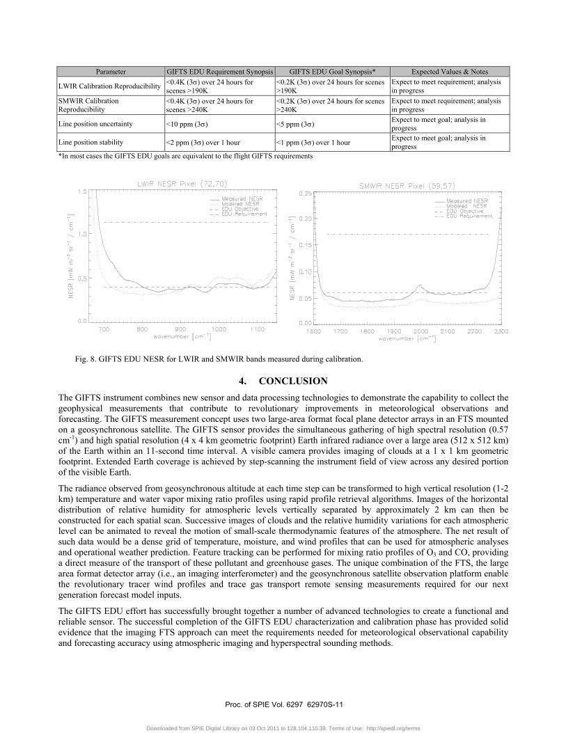
Noise equivalent spectral radiance (NESR) is a fundamental performance criterion of an interferometer-based sensor. The dominant noise source for the GIFTS EDU is readout noise in both the LWIR and the SMWIR bands. The GIFTS design was optimized to achieve a reasonable balance among the requirements for the critical subsystems, including the focal plane cooler, the ADCs, and the detector readout well capacity. Thermally generated noise is the second largest contributor to the instrument NESR for the LWIR. For the SMWIR band, the thermally generated noise contribution is insignificant. Overall noise performance of the GIFTS EDU is shown in Fig. 8. As the figure shows, the GIFTS EDU easily meets the EDU requirement, and meets or is close to the goal, or flight requirement, over almost all of the spectral bands.
Table 2. Summary of GIFTS EDU requirements and expected performance.
Parameter GIFTS EDU Requirement Synopsis GIFTS EDU Goal Synopsis* Expected Values & Notes
LWIR NESR
<0.4 mW/(m2·sr·cm-1) for wavenumbers >700 cm-1; 1.2 cm-1 resolution; scenes <276 K, 2x2 pixel
<0.4 mW/(m2·sr·cm-1) for wavenumbers >700 cm-1, 0.57 cm-1 resolution scenes < 276 K; single pixel
Meets requirement Meets goal over most of spectral range (see Fig. 8)
SMWIR NESR <0.06 mW/(m2·sr·cm-1) for 1.2 cm-1
resolution, scenes <260 K, 2x2 pixel
<0.06 mW/(m2·sr·cm-1) for 0.57 cm-1 resolution, scenes <260 K; single pixel
Meets requirement Meets goal over most of spectral range (see Fig. 8)
LWIR Dynamic Range 197K to 309K Meets requirement SMWIR Dynamic Range 204K to 286K Meets requirement LWIR Operability >50% >75% >95%, meets goal SMWIR Operability >60% >85% >95%, meets goal Ensquared energy at 11 µm >0.55 >0.67 Meets requirement
LWIR Calibration error <1K (3σ) for scenes between 197K and 309K Expect to meet requirement; analysis
in progress
SMWIR Calibration Error <1K (3σ) for scenes between 204K to 286K Expect to meet requirement; analysis
in progress
Proc. of SPIE Vol. 6297 62970S-10
Downloaded from SPIE Digital Library on 03 Oct 2011 to 128.104.110.39. Terms of Use: http://spiedl.org/terms
Parameter GIFTS EDU Requirement Synopsis GIFTS EDU Goal Synopsis* Expected Values & Notes
LWIR Calibration Reproducibility <0.4K (3σ) over 24 hours for scenes >190K
<0.2K (3σ) over 24 hours for scenes >190K
Expect to meet requirement; analysis in progress
SMWIR Calibration Reproducibility
<0.4K (3σ) over 24 hours for scenes >240K
<0.2K (3σ) over 24 hours for scenes >240K
Expect to meet requirement; analysis in progress
Line position uncertainty <10 ppm (3σ) <5 ppm (3σ) Expect to meet goal; analysis in progress
Line position stability <2 ppm (3σ) over 1 hour <1 ppm (3σ) over 1 hour Expect to meet goal; analysis in progress
*In most cases the GIFTS EDU goals are equivalent to the flight GIFTS requirements
Fig. 8. GIFTS EDU NESR for LWIR and SMWIR bands measured during calibration.
4. CONCLUSION The GIFTS instrument combines new sensor and data processing technologies to demonstrate the capability to collect the geophysical measurements that contribute to revolutionary improvements in meteorological observations and forecasting. The GIFTS measurement concept uses two large-area format focal plane detector arrays in an FTS mounted on a geosynchronous satellite. The GIFTS sensor provides the simultaneous gathering of high spectral resolution (0.57 cm-1) and high spatial resolution (4 x 4 km geometric footprint) Earth infrared radiance over a large area (512 x 512 km) of the Earth within an 11-second time interval. A visible camera provides imaging of clouds at a 1 x 1 km geometric footprint. Extended Earth coverage is achieved by step-scanning the instrument field of view across any desired portion of the visible Earth.
The radiance observed from geosynchronous altitude at each time step can be transformed to high vertical resolution (1-2 km) temperature and water vapor mixing ratio profiles using rapid profile retrieval algorithms. Images of the horizontal distribution of relative humidity for atmospheric levels vertically separated by approximately 2 km can then be constructed for each spatial scan. Successive images of clouds and the relative humidity variations for each atmospheric level can be animated to reveal the motion of small-scale thermodynamic features of the atmosphere. The net result of such data would be a dense grid of temperature, moisture, and wind profiles that can be used for atmospheric analyses and operational weather prediction. Feature tracking can be performed for mixing ratio profiles of O3 and CO, providing a direct measure of the transport of these pollutant and greenhouse gases. The unique combination of the FTS, the large area format detector array (i.e., an imaging interferometer) and the geosynchronous satellite observation platform enable the revolutionary tracer wind profiles and trace gas transport remote sensing measurements required for our next generation forecast model inputs.
The GIFTS EDU effort has successfully brought together a number of advanced technologies to create a functional and reliable sensor. The successful completion of the GIFTS EDU characterization and calibration phase has provided solid evidence that the imaging FTS approach can meet the requirements needed for meteorological observational capability and forecasting accuracy using atmospheric imaging and hyperspectral sounding methods.
Proc. of SPIE Vol. 6297 62970S-11
Downloaded from SPIE Digital Library on 03 Oct 2011 to 128.104.110.39. Terms of Use: http://spiedl.org/terms

REFERENCES
1. Hanel, R.A., B.Schlachman, F.D. Clark, C.H. Prokesh, J.B. Taylor, W.M. Wilson and L.Chaney, 1970: The Nimbus III Michelson interferometer. Appl. Optics, 9, 1767
2. Ahmadjian, M., R.M. Nadile, J.O. Wise, and B. Bartschi. 1990: CIRRIS – 1A Space Shuttle Experiment. J. Spacecraft, 27, 669-674
3. Bartschi, B., J.C. Kemp, D.A. Burt, G.D. Allred, and L.J. Zollinger. 1987: Optical Techniques for Sensing and Measurement in Hostile Environments. Proceedings SPIE, 787, 119-127
4. Revercomb, H.E., D.D. LaPorte, W.L. Smith, H. Buijs, D.G. Murcray, F.J. Murcray, and L.A. Sromovsky. 1988: High-altitude aircraft measurements of upwelling IR radiance: prelude to FTIR from geosynchronous satellite. Mikrochim. Acta, II, 439-444
5. Smith, W.L., H.M. Woolf, H.B. Howell, H.L. Huang and H.E. Revercomb, 1988: The simultaneous retrieval of atmospheric temperature and water vapor profiles – applications to measurements with the High spectral resolution Interferometer Sounder (HIS), RSRM 87; Advances in Remote Sensing Retrieval Methods. A. Deepak, H. Fleming and j. Theon, Eds, A Deepak
6. Cousins, D., and W. L. Smith, "National Polar-Orbiting Operational Environmental Satellite System (NPOESS) Airborne Sounder Testbed-Interferometer (NAST-I)", Proceedings of SPIE, 3127, 323–331, 1997.
7. Smith, W.L., D.K. Zhou, A.M. Larar. 2000: Hyperspectral remote sensing of atmospheric profiles from satellites and aircraft. In Hyperspectral Remote Sensing of the Land and Atmosphere, Remote Sensing of the Atmosphere, Environment, and Space, Sendai, Japan, October 9-12
8. Smith, W.L., H.E. Revercomb, H.B. Howell, H.L. Huang, R.O. Knuteson, E.W. Koenig. D.D. LaPorte, S. Silverman, L.A. Sromovsky, and H.M. Woolf, 1990: GHIS – The GOES High-Resolution Interferometer Sounder. J. Meterology, 29, 1189-1204
9. Potter, A.E. Jr., 1972: Multispectral Imaging System, U.S. Patent # 3702735, November 14 10. Huppi, R.J., R.B. Shipley, and E.R. Hippi, 1979: Balloonborne Fourier Spectrometer Using a Focal Plane Detector
Array, SPIE Proceedings, 191 11. Fetrow, M.P. and R.J. Huppi. 1993: Experimental and Modeling Investigation of a 3-5 µm Imaging Spectrometer,
SPIE Proceedings, 2019 12. Bennett, C.L., M.R. Carter, D.J. Fields, 1995; Hyperspectral Imaging in the Infrared using LIFTIRS, Infrared
Technology XXI, SPIE Proceedings, 1937, 274-283 13. Best, F.A., H.E. Revercomb, G.E. Bingham, R.O. Knuteson, D.C. Tobin, D.D. LaPorte, and W.L. Smith. 2000:
Calibration of the Geostationary Imaging Fourier Transform spectrometer (GIFTS). In Hyperspectral Remote Sensing of the Land and Atmosphere, Remote Sensing of the Atmosphere, Env. & Space, Sendai, Japan, Oct. 9-12 2000.
14. Tobin, D. C., H. E. Revercomb, R. O. Knuteson, 2003: “On-orbit Spectral Calibration of the Geosynchronous Imaging Fourier Transform Spectrometer (GIFTS)” in Proceedings of CALCON 2003, Characterization and Radiometric Calibration for Remote Sensing, Space Dynamics Laboratory/USU, Logan, UT, 15-18 Sept. 2003.
15. Elwell, J. D., D. K. Scott, H. E. Revercomb, F. A. Best, R. O. Knuteson, 2003 : “An overview of Ground and On-orbit Characterization and Calibration of the Geosynchronous Imaging Fourier Transform Spectrometer (GIFTS)” in Proceedings of CALCON 2003, Characterization and Radiometric Calibration for Remote Sensing, Space Dynamics Laboratory/USU, Logan, UT, 15-18 Sept. 2003.
16. Elwell, J. E., D. K. Scott, 2003: “A Method for Correcting for Telescope Spectral Transmission in the Geosynchronous Imaging Fourier Transform Spectrometer (GIFTS)” in Proceedings of CALCON 2003, Characterization and Radiometric Calibration for Remote Sensing, Space Dynamics Laboratory/USU, Logan, UT, 15-18 Sept. 2003.
17. Best, F. A., H. E. Revercomb, R. O. Knuteson, D. C. Tobin, S. D. Ellington, M. W. Werner, D. P. Adler, R. K., Garcia, J. K. Taylor, N. N. Ciganovich, W. L. Smith, G. E. Bingham, J. D. Elwell, and D. K. Scott, 2004: “The Geosynchronous Imaging Fourier Transform Spectrometer (GIFTS) On-board Blackbody Calibration System” In: Proceedings of the SPIE, Fourth International Asia-Pacific Environmental Remote Sensing Symposium, 8 Nov. 2004, Honolulu, Hawaii.
Proc. of SPIE Vol. 6297 62970S-12
Downloaded from SPIE Digital Library on 03 Oct 2011 to 128.104.110.39. Terms of Use: http://spiedl.org/terms