A Generalized Method to Investigate the Bistability of ... · A Generalized Method to Investigate...
12
2 nd International and 17 th National Conference on Machines and Mechanisms iNaCoMM2015-73 A Generalized Method to Investigate the Bistability of Curved Beams using Buckling Analysis Safvan P *, 1 , Darshan S *, 2 , Anirudh N Katti *, 3 , G.K.Ananthasuresh *, 4 Abstract In this paper, an initially straight beam with torsional springs at its two hinged ends is subjected to an axial force and its buckling mode shapes are found. Any shape which is a linear combination of the modes is taken as the as-fabricated stress-free form and then subjected to a transverse actuating force. Post-buckling analysis is used to compute the force-displacement characteristic of such a beam and thereby check if bistability exists. Two special cases of the torsion spring constants being very large and zero are presented. The former is a known result where a cosine curve is the fundamental buckling mode that does not give bistability unless its asymmetric second mode shape is avoided by a physical constraint. When the spring constant is zero, a single sine curve profile, which is the fundamental mode, can be made bistable without having to physically constrain the asymmetric buckling modes. This is realized when pinned-pinned boundary condition is used, which further allows the element to have enhanced range of travel between its two stable states, reduced switching force, and provision for secondary lateral actuation. To realise a monolithic compliant bistable element without any kinematic joints, torsion springs are substituted with equivalent revolute flexures. Physical embodiments of three types of bistable curved beams, namely, fixed-fixed, pinned- pinned, and revolute flexure-based, are presented. Keywords: Fully-compliant mechanisms, revolute flexures, buckling modes 1 Introduction Mechanisms which have two force-free stable equilibrium positions in their range of motion are called bistable mechanisms. Their characteristic force and energy graphs are shown in Fig. 1. Bistable mechanisms are used in both macro-scale and micro- scale applications. Relays [1][2], micro-actuators [3] micro-valves [4] and mechanical memory components [5] are examples of bistable micro devices. Circuit breakers, switches, easy-chairs [6] and rear trunk lids of cars [7] are examples of macro-scale bistable devices. In this paper we present a generalized method to investigate the bistability of curved beams and to design monolithic fully-compliant bistable mechanisms with enhanced performance. One way to obtain bistability in curved beams is to use linear combinations of buckling mode shapes of a straight beam. Most bistable mechanism reported in the literature employ fixed-fixed boundary conditions. For fixed-fixed boundary conditions, the mode shapes of a straight beam are as shown in Fig. 2. If the first cosine buckling mode shape is used as the bistable mechanism’s as-fabricated shape, Qui et at. [8] proved that the mechanism does not exhibit bistability unless its ________________ * Department of Mechanical Engineering, Indian Institute of Science, Bengaluru, India 1 Email: [email protected] 2 Email: [email protected] 3 Email: [email protected] 4 (Corresponding author) Email: [email protected] 1
Transcript of A Generalized Method to Investigate the Bistability of ... · A Generalized Method to Investigate...

2nd International and 17th National Conference on Machines and Mechanisms iNaCoMM2015-73
A Generalized Method to Investigate the Bistability of Curved Beams using Buckling Analysis
Safvan P*, 1, Darshan S*, 2, Anirudh N Katti*, 3, G.K.Ananthasuresh*, 4
Abstract
In this paper, an initially straight beam with torsional springs at its two hinged
ends is subjected to an axial force and its buckling mode shapes are found. Any shape which is a linear combination of the modes is taken as the as-fabricated stress-free form and then subjected to a transverse actuating force. Post-buckling analysis is used to compute the force-displacement characteristic of such a beam and thereby check if bistability exists. Two special cases of the torsion spring constants being very large and zero are presented. The former is a known result where a cosine curve is the fundamental buckling mode that does not give bistability unless its asymmetric second mode shape is avoided by a physical constraint. When the spring constant is zero, a single sine curve profile, which is the fundamental mode, can be made bistable without having to physically constrain the asymmetric buckling modes. This is realized when pinned-pinned boundary condition is used, which further allows the element to have enhanced range of travel between its two stable states, reduced switching force, and provision for secondary lateral actuation. To realise a monolithic compliant bistable element without any kinematic joints, torsion springs are substituted with equivalent revolute flexures. Physical embodiments of three types of bistable curved beams, namely, fixed-fixed, pinned-pinned, and revolute flexure-based, are presented.
Keywords: Fully-compliant mechanisms, revolute flexures, buckling modes
1 Introduction Mechanisms which have two force-free stable equilibrium positions in their range of motion are called bistable mechanisms. Their characteristic force and energy graphs are shown in Fig. 1. Bistable mechanisms are used in both macro-scale and micro-scale applications. Relays [1][2], micro-actuators [3] micro-valves [4] and mechanical memory components [5] are examples of bistable micro devices. Circuit breakers, switches, easy-chairs [6] and rear trunk lids of cars [7] are examples of macro-scale bistable devices. In this paper we present a generalized method to investigate the bistability of curved beams and to design monolithic fully-compliant bistable mechanisms with enhanced performance. One way to obtain bistability in curved beams is to use linear combinations of buckling mode shapes of a straight beam. Most bistable mechanism reported in the literature employ fixed-fixed boundary conditions. For fixed-fixed boundary conditions, the mode shapes of a straight beam are as shown in Fig. 2. If the first cosine buckling mode shape is used as the bistable mechanism’s as-fabricated shape, Qui et at. [8] proved that the mechanism does not exhibit bistability unless its
________________ * Department of Mechanical Engineering, Indian Institute of Science, Bengaluru, India 1 Email: [email protected] 2 Email: [email protected] 3 Email: [email protected] 4 (Corresponding author) Email: [email protected]
1

2nd International and 17th National Conference on Machines and Mechanisms iNaCoMM2015-73
asymmetric second mode shape is prevented by a physical constraint. They proposed a monolithic compliant bistable mechanism that uses two cosine curved centrally-clamped parallel beams shown in Fig. 3 as its as-fabricated shape. Such a shape is given by 𝑤𝑤� =
ℎ2�1 − cos �
2𝜋𝜋𝜋𝜋𝐿𝐿�� (1)
where ℎ is the apex height of the beam and 𝐿𝐿 distance between the ends.
Fig. 1. Bistable mechanism force and energy behaviour
Fig. 2. Fixed-fixed boundary condition mode shapes
Fig. 3. Two cosine curved centrally-clamped parallel beams bistable mechanism
On the other hand, if pinned-pinned boundary conditions are used, the modes shapes are as shown in Fig. 4. A single sine curve profile, which is the fundamental mode, can be made bistable without having to physically constrain the asymmetric buckling modes. It is given by 𝑤𝑤� = ℎ sin �
𝜋𝜋𝜋𝜋𝐿𝐿� (2)
A bistable curved beam with pinned-pinned boundary conditions possesses advantages over the curved fixed-fixed beam. They have enhanced range of travel between its two stable states, reduced switching force, and provision for secondary lateral actuation. However, pin joints at micro scale lead to difficulties in manufacturing and problems in operation due to friction and wear. Therefore, the intermediate case of hinged ends with rotational flexures is an option worth
Ener
gy
State 2 Position State 1
F=0
Forc
e
Mode 3
Mode 2
Mode 1
2

2nd International and 17th National Conference on Machines and Mechanisms iNaCoMM2015-73
exploring. This approach, as demonstrated in this paper, gives rise to hinge-free monolithic designs while retaining the aforementioned three advantages.
Fig. 4. Pinned-pinned boundary condition mode shapes
In this paper, we propose to replace the pin joints with compliant revolute joints. Towards this, a bistable element is designed by following a systematic buckling analysis-based procedure. The torsional stiffness is lumped into a torsion spring at the revolute joint for the purposes of modelling. The buckling mode shapes for such a beam are found in Section 2. The as-fabricated profile is taken as a linear combination of the buckling modes. The potential energy of the system is found and minimized with respect to mode weights to obtain the force-displacement relationship, which can be used to check if the mechanism is bistable. In Section 3, we present designs of three types of bistable elements, namely, fixed-fixed, pinned-pinned, and revolute flexure-based.
2 Analysis of the beam with general boundary conditions
2.1 Buckling Analysis
The governing differential equation for a generally constrained beam shown in Fig. 5, subjected to axial load 𝑃𝑃 is given by
𝐸𝐸𝐸𝐸𝑑𝑑4𝑤𝑤𝑑𝑑𝜋𝜋4
+ 𝑃𝑃𝑑𝑑2𝑤𝑤𝑑𝑑𝜋𝜋2
= 0 (3)
where 𝑤𝑤 is the transverse displacement of the beam perpendicular to the axial force, 𝐸𝐸 is the Young’s modulus of the material, and 𝐸𝐸 is area moment of inertia of the cross-section of the beam. Further, the length of the beam is 𝐿𝐿, the axial force 𝑃𝑃 and the torsional spring constant is 𝜅𝜅.
Fig. 5. A generally constrained beam subjected to axial force
We use the notation 𝑀𝑀 to condense the force, material property and cross-section property. Note that 𝑀𝑀 here does not stand for the bending moment.
P 𝜅𝜅 𝜅𝜅
x=0 x=L
3

2nd International and 17th National Conference on Machines and Mechanisms iNaCoMM2015-73
𝑀𝑀 = �𝑃𝑃
𝐸𝐸𝐸𝐸 (4)
The solution to Eq. (3) is of the form 𝑑𝑑2𝑤𝑤
𝑑𝑑𝜋𝜋2= 𝐴𝐴 cos(𝑀𝑀𝜋𝜋) + 𝐵𝐵 sin(𝑀𝑀𝜋𝜋) (5)
By integrating twice, we get 𝑤𝑤 = −
𝐴𝐴𝑀𝑀2 cos(𝑀𝑀𝜋𝜋) −
𝐵𝐵𝑀𝑀2 sin(𝑀𝑀𝜋𝜋) + 𝐶𝐶𝜋𝜋 + 𝐷𝐷 (6)
where 𝐴𝐴, B, 𝐶𝐶 and 𝐷𝐷 are constants. The boundary conditions are given by 𝑤𝑤|𝑥𝑥=0 = 𝑤𝑤|𝑥𝑥=𝐿𝐿 = 0 (7)
𝐸𝐸𝐸𝐸𝑑𝑑2𝑤𝑤𝑑𝑑𝜋𝜋2
�𝑥𝑥=0
= 𝜅𝜅𝑑𝑑𝑤𝑤𝑑𝑑𝜋𝜋
�𝑥𝑥=0
, 𝐸𝐸𝐸𝐸𝑑𝑑2𝑤𝑤𝑑𝑑𝜋𝜋2
�𝑥𝑥=𝐿𝐿
= 𝜅𝜅𝑑𝑑𝑤𝑤𝑑𝑑𝜋𝜋
�𝑥𝑥=𝐿𝐿
(8)
By applying the boundary conditions in Eq. (5) and Eq. (6), we get 𝐶𝐶 =
𝐸𝐸𝐸𝐸𝐴𝐴𝜅𝜅
+𝐵𝐵𝑀𝑀
𝐷𝐷 =𝐴𝐴𝑀𝑀2
(9)
Using Eqs. (5), (6), (7), (8) and (9) to reduce to a system of two equations in two unknowns 𝐴𝐴 and 𝐵𝐵 gives rise to
�−
cos(𝑀𝑀𝐿𝐿)𝑀𝑀2 +
1𝑀𝑀2 +
𝐸𝐸𝐸𝐸𝐿𝐿𝜅𝜅
−sin(𝑀𝑀𝐿𝐿)𝑀𝑀2 +
𝐿𝐿𝑀𝑀
cos(𝑀𝑀𝐿𝐿) −𝜅𝜅 sin(𝑀𝑀𝐿𝐿)𝑀𝑀𝐸𝐸𝐸𝐸
− 1 sin(𝑀𝑀𝐿𝐿) +𝜅𝜅 cos(𝑀𝑀𝐿𝐿)𝑀𝑀𝐸𝐸𝐸𝐸
−𝜅𝜅
𝑀𝑀𝐸𝐸𝐸𝐸
� �𝐴𝐴𝐵𝐵� = �00�
(10)
For a non-trivial solution, we equate the determinant of the matrix in Eq. (10) to zero, which yields the condition:
𝑠𝑠𝑠𝑠𝑠𝑠 �𝑀𝑀𝐿𝐿2� �𝑐𝑐𝑐𝑐𝑠𝑠 �
𝑀𝑀𝐿𝐿2� �𝐸𝐸2𝐸𝐸2𝐿𝐿𝜅𝜅2
+𝐿𝐿𝑀𝑀2� −
2𝑀𝑀3 𝑠𝑠𝑠𝑠𝑠𝑠 �
𝑀𝑀𝐿𝐿2�� = 0 (11)
Eq. (11) can be used to find the buckling mode shapes. For 𝜅𝜅 = 0, the mode shapes are the sine mode shapes as shown in Fig. 4. For 𝜅𝜅 = ∞, the mode shapes are the cosine mode shapes as shown in Fig. 2. For intermediate values, with geometric and material parameters shown in Table 1, the buckling mode shapes are as shown in Fig. 6. Here 𝑏𝑏 is the out-of-plane depth of the beam and 𝑡𝑡 is the thickness of the beam.
Table 1. Geometric and material parameters of a beam
S.No. Parameter Value 1 L 0.125 m 2 b 0.005 m 3 t 0.001 m 4 E 2.1 GPa
5 h 0.011 m
4

2nd International and 17th National Conference on Machines and Mechanisms iNaCoMM2015-73
a. 𝜅𝜅 = 0.00525 Nm/rad
b. 𝜅𝜅 = 0.01 Nm/rad
c. 𝜅𝜅 = 0.2 Nm/rad
Fig. 6. Buckling mode shapes for a beam with different torsional stiffness values
For 𝜅𝜅 > 0.503 Nm/rad, the mode shapes closely resemble those of fixed-fixed boundary condition. For 𝜅𝜅 < 0.01 Nm/rad, the mode shapes closely resemble those of pinned-pinned boundary condition.
2.2 Post-buckling analysis
Any shape which is a combination of the buckling modes can be taken as the as-fabricated shape of the bistable element (𝑤𝑤�). When the element of such a shape is subjected to a transverse force, it may or may not exhibit bistability. We now discuss a method to check for the bistability.
The buckling mode shapes found in Section 2.1 are orthonormal to one another. They form the basis vectors for the given torsional stiffness, i.e., any shape can be written as a linear combination of these basis vectors. Hence, the deformed shape of the bistable beam can also be written as a linear combination of the basis vectors. For simplicity, we will first assume the deformed shape (𝑤𝑤) of the beam to be a linear combination of the first two mode shapes, i.e. 𝑤𝑤 = 𝐴𝐴1𝑤𝑤1 + 𝐴𝐴2𝑤𝑤2 (11) where 𝐴𝐴1 and 𝐴𝐴2 are the mode weights. In order to determine the force-displacement curve of the bistable element, we will minimize the potential energy of the system with respect to both 𝐴𝐴1 and 𝐴𝐴2. The potential energy is given by
5

2nd International and 17th National Conference on Machines and Mechanisms iNaCoMM2015-73
𝑃𝑃𝐸𝐸 = 𝑆𝑆𝐸𝐸𝑏𝑏 + 𝑆𝑆𝐸𝐸𝑐𝑐 −𝑊𝑊𝑃𝑃𝑓𝑓 +
12𝜅𝜅 �𝑑𝑑𝑤𝑤𝑑𝑑𝜋𝜋
�𝑥𝑥=0
�2
+12𝜅𝜅 �𝑑𝑑𝑤𝑤𝑑𝑑𝜋𝜋
�𝑥𝑥=𝐿𝐿
�2
(12)
where 𝑆𝑆𝐸𝐸𝑏𝑏 is the strain energy associated with the bending of the element, 𝑆𝑆𝐸𝐸𝑐𝑐 is the strain energy associated with deformation due to compression and 𝑊𝑊𝑃𝑃𝑓𝑓 is the work potential due to transverse force 𝑓𝑓. When more than one beam element is used, the bending energy and compression energy for each element has to be accounted for. The work potential term however, remains the same. For example, in the two cosine curved mechanism (Fig. 3), an additional 𝑆𝑆𝐸𝐸𝑏𝑏 + 𝑆𝑆𝐸𝐸𝑐𝑐 should be added to Eq. (13) as there are two beam elements. 𝑆𝑆𝐸𝐸𝑏𝑏 and 𝑆𝑆𝐸𝐸𝑐𝑐 for a single beam element are given by
𝑆𝑆𝐸𝐸𝑏𝑏 =𝐸𝐸𝐸𝐸2� �
𝑑𝑑2𝑤𝑤�𝑑𝑑𝜋𝜋2
−𝑑𝑑2𝑤𝑤𝑑𝑑𝜋𝜋2
�2
𝑑𝑑𝜋𝜋𝐿𝐿
0 (13)
𝑆𝑆𝐸𝐸𝑐𝑐 = −
𝐿𝐿2𝑏𝑏𝑡𝑡𝐸𝐸
�𝑠𝑠 −𝑠𝑠2
2�̅�𝑠−�̅�𝑠2�
𝑠𝑠 = � �1 + �𝑑𝑑𝑤𝑤𝑑𝑑𝜋𝜋
�2
𝑑𝑑𝜋𝜋𝐿𝐿
0≈ � �1 +
12�𝑑𝑑𝑤𝑤𝑑𝑑𝜋𝜋
�2
�𝐿𝐿
0𝑑𝑑𝜋𝜋
�̅�𝑠 = � �1 +12�𝑑𝑑𝑤𝑤�𝑑𝑑𝜋𝜋
�2
�𝐿𝐿
0𝑑𝑑𝜋𝜋
(14)
𝑊𝑊𝑃𝑃𝑓𝑓 = −𝑓𝑓𝑑𝑑 (15) 𝑑𝑑 = 𝑤𝑤� �
𝐿𝐿2� − 𝑤𝑤 �
𝐿𝐿2� (16)
For static equilibrium, we have: 𝜕𝜕(𝑃𝑃𝐸𝐸)
𝜕𝜕𝐴𝐴1= 0 (17)
𝜕𝜕(𝑃𝑃𝐸𝐸)𝜕𝜕𝐴𝐴2
= 0 (18)
Equations (17), (18) and (19) become a system of three equations in three unknowns: 𝑓𝑓, 𝐴𝐴1 and 𝐴𝐴2. There are two possible solutions to this system: one when the energy of the system does not equal the energy of the second buckling mode, and the other when it does. Solving both numerically gives the force-displacement curve. Similarly, when we consider more than two mode shapes, we get additional equations to solve.
2.3 An illustrative example
To illustrate the method, we consider the split-tube flexure described in [9] where torsional stiffness is 𝜅𝜅 = 0.00525. The mode shapes can be found using Eq. (11) are shown in Fig. 6a. The as-fabricated shape is taken to be the first mode. For the first mode, the values of constants in Eq. (6) are given by 𝐴𝐴 = 0.2205,𝐵𝐵 = −1.0000,𝐶𝐶 = −0.002,𝐷𝐷 = 0.0003,𝑀𝑀 = 27.1263 (19)
Then Eq. (6) becomes 𝑤𝑤 = (2.9887 cos(27.1623𝜋𝜋) + 14 sin(27.1623𝜋𝜋) − 20𝜋𝜋 + 3)10−4 (20)
6

2nd International and 17th National Conference on Machines and Mechanisms iNaCoMM2015-73
Removing the constant terms and modifying the equation such that ℎ would be the apex height in meters, the equation of the as-fabricated shape of the bistable element is given by 𝑤𝑤� = ℎ(−0.1918 cos(27.1623𝜋𝜋) + 0.8699 sin(27.1623𝜋𝜋) − 1.2836𝜋𝜋
+ 0.1925) (21)
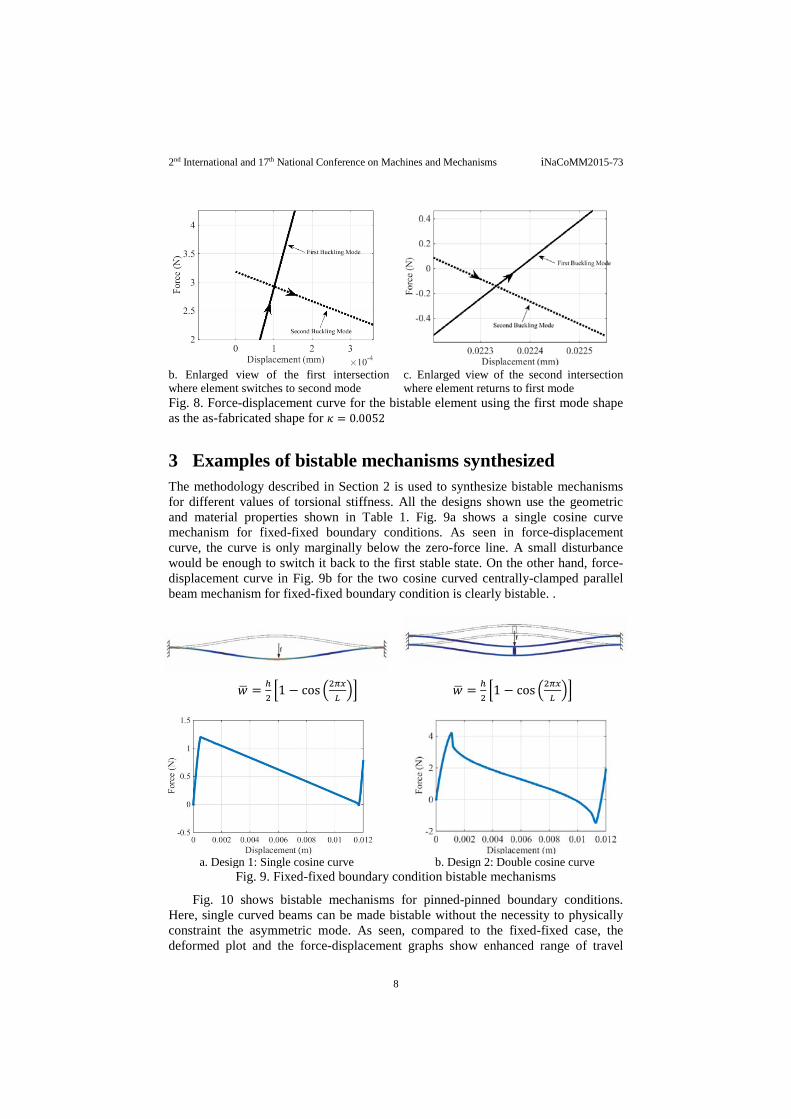
The bistable element is shown in Fig. 7 and the force-displacement curve is shown in Fig. 8. Fig. 8 shows a curve and a straight line, corresponding the two solutions discussed in the end of Section 2.2. As the element is deformed, it travels along the curve until it reaches the dotted line, corresponding to the second buckling mode, as shown in Fig. 8a. At the point the curve intersects the straight line, it deforms into the second buckling mode shape (Fig. 8b). It then travels along the straight line till it once again intersects the curve. At this point, the element returns to the first buckling mode shape (Fig. 8c) and reaches the second equilibrium state. Hence, the actual force-displacement curve is a hybrid that switches between the curve and the straight line at the intersections. It should be observed in Fig. 8c, that the point at which the element returns to the first buckling mode is below the zero force line, and hence, the element is bistable. If on the other hand, the intersection point was above the zero-force line, the mechanism would bounce back when the actuating force is released, and hence, wouldn’t be bistable.
Fig. 7. Bistable element using the first mode shape as the as-fabricated shape for 𝜅𝜅 =0.00525
a. Hybrid force-displacement curve for both solutions
7
2nd International and 17th National Conference on Machines and Mechanisms iNaCoMM2015-73
b. Enlarged view of the first intersection where element switches to second mode
c. Enlarged view of the second intersection where element returns to first mode
Fig. 8. Force-displacement curve for the bistable element using the first mode shape as the as-fabricated shape for 𝜅𝜅 = 0.0052
3 Examples of bistable mechanisms synthesized The methodology described in Section 2 is used to synthesize bistable mechanisms for different values of torsional stiffness. All the designs shown use the geometric and material properties shown in Table 1. Fig. 9a shows a single cosine curve mechanism for fixed-fixed boundary conditions. As seen in force-displacement curve, the curve is only marginally below the zero-force line. A small disturbance would be enough to switch it back to the first stable state. On the other hand, force-displacement curve in Fig. 9b for the two cosine curved centrally-clamped parallel beam mechanism for fixed-fixed boundary condition is clearly bistable. .
𝑤𝑤� = ℎ2�1 − cos �2𝜋𝜋𝑥𝑥
𝐿𝐿�� 𝑤𝑤� = ℎ
2�1 − cos �2𝜋𝜋𝑥𝑥
𝐿𝐿��
a. Design 1: Single cosine curve b. Design 2: Double cosine curve
Fig. 9. Fixed-fixed boundary condition bistable mechanisms
Fig. 10 shows bistable mechanisms for pinned-pinned boundary conditions. Here, single curved beams can be made bistable without the necessity to physically constraint the asymmetric mode. As seen, compared to the fixed-fixed case, the deformed plot and the force-displacement graphs show enhanced range of travel
8

2nd International and 17th National Conference on Machines and Mechanisms iNaCoMM2015-73
between its two stable states and reduced switching force. Fig. 10b shows the optimized bistable curve for pinned-pinned boundary condition. Optimization was carried for maximum range of travel for a given actuation force taking first three mode weights, 𝐴𝐴1,𝐴𝐴2 and 𝐴𝐴3, as the design variables.
𝑤𝑤� = ℎ sin �𝜋𝜋𝜋𝜋𝐿𝐿� 𝑤𝑤� = 33.8 �0.4634 sin �
𝜋𝜋𝜋𝜋𝐿𝐿� + 0.0653 sin �
3𝜋𝜋𝜋𝜋𝐿𝐿�
− 0.0724 sin �5𝜋𝜋𝜋𝜋𝐿𝐿��
a. Design 1: Sine curve b. Design 2 : Optimized curve
Fig. 10. Pinned-pinned boundary condition bistable mechanisms
Prototypes of the mechanisms shown in Fig. 9 and Fig. 10 are shown in Fig. 11. Fig. 11a is the single cosine curve mechanism with fixed-fixed boundary condition. This mechanism isn’t bistable and hence has only one state. Fig. 11b is the double cosine curve mechanism with fixed-fixed boundary condition. This mechanism is bistable. We measure the apex height ℎ and the travel 𝑡𝑡𝑟𝑟 in each mechanism. As ℎ could be different in the prototypes, the ratio 𝑡𝑡𝑟𝑟
ℎ is an indicative of the travel between
the two states factoring in the apex height. The greater the ratio, the greater the travel.
a. Fixed-fixed single cosine curve monostable mechanism
Prototype in state 1 Prototype in state 2 b. Fixed-fixed double cosine curve mechanism [8] (𝑡𝑡𝑟𝑟
ℎ= 18
11= 1.64)
Prototype in state 1 Prototype in state 2
c. Pinned-pinned sine curve mechanism (𝑡𝑡𝑟𝑟ℎ
= 2111
= 1.90)
9

2nd International and 17th National Conference on Machines and Mechanisms iNaCoMM2015-73
Prototype in state 1 Prototype in state 2
d. Pinned-pinned first three sine modes linear combination mechanism (𝑡𝑡𝑟𝑟ℎ
= 3011
= 2.72) Fig. 11. Fixed-fixed and pinned-pinned bistable mechanisms
In Fig. 11c, the sine curve mechanism is shown. In this mechanism, the pin
joints are used to add an appendage which would allow for lateral actuation. Fig. 11d shows an optimized mechanism for pinned-pinned boundary condition. This mechanism has the largest 𝑡𝑡𝑟𝑟
ℎ ratio.
Fig. 12 shows a bistable mechanism with revolute flexures. The basic shape used is a cosine curve. Revolute flexures at both ends prevent axial motion but allow rotation. As with the case with pinned-pinned boundary conditions, the deformed shape and the force-displacement curve show enhanced range of travel between its two stable states and reduced switching force compared to the fixed-fixed case.
a. Deformation plot of the mechanism
b. FEA force-displacement curve
c. Prototype in state 1
10

2nd International and 17th National Conference on Machines and Mechanisms iNaCoMM2015-73
d. Prototype in state 2
Fig. 12. Prototype of revolute flexure bistable mechanisms (𝑡𝑡𝑟𝑟ℎ
= 178
= 2.215)
4 Conclusions This paper proposed a methodology to investigate bistable mechanisms with compliant revolute flexures at both ends and to aide in their design. The flexures, being close to pinned-pinned boundary allow for the design of efficient bistable mechanisms, i.e., they allow the element to have enhanced range of travel between its two stable states, reduced switching force, and provision for secondary lateral actuation. Based on the analysis, we have synthesised and presented bistable mechanisms: two for pinned-pinned boundary condition and one with revolute flexures. Acknowledgement The authors gratefully acknowledge the financial support from the Department of Science and Technology (DST) and Technology Initiative for the Disabled and the Elderly (TIDE) of the Government of India. References [1] Qiu, Jin, Jeffrey H. Lang, Alexander H. Slocum, and Alexis C. Weber. “A bulk-
micromachined bistable relay with U-shaped thermal actuators”, Journal of Microelectromechanical Systems, No. 5, 2005, pg 1099-1109
[2] Troy Gomm, Larry L Howell and Richard H Selfridge, “In-plane linear displacement bistable microrelay”, Journal of Micromechanics and Microengineering, Vol. 12, 2002, Pages 257-264
[3] Matoba, Hirotsugu, Toshio Ishikawa, Chang Jin Kim, and Richard S. Muller. "A bistable snapping microactuator." In Micro Electro Mechanical Systems, 1994, MEMS'94, Proceedings, IEEE Workshop on, pp. 45-50. IEEE, 1994.
[4] Rajesh Luharuka and Peter J Hesketh , “A bistable electromagnetically actuated rotary gate microvalve”, Journal of Micromechanics and Microengineering, Vol. 18, 2008, doi:10.1088/0960-1317/18/3/035015
[5] Hälg, B. "On a nonvolatile memory cell based on micro-electro-mechanics." In/Micro Electro Mechanical Systems, 1990. Proceedings, An Investigation of Micro Structures, Sensors, Actuators, Machines and Robots. IEEE/, pp. 172-176. IEEE, 1990
[6] S Darshan, T.J.Lassche, J.L.Herder, G.K.Ananthasuresh, “A Compliant Two-Port Bistable Mechanism with Application to Easy-Chair Design”, 14th World Congress in Mechanism and Machine Science, Taipei, Taiwan, October 25-30, 2015
[7] Zhang, Shouyin, Guimin Chen, “Design of compliant bistable mechanism for rear trunk lid of cars”, Intelligent Robotics and Applications, Springer Berlin, Heidelberg, pp291-299, 2011
[8] Jin Qiu, Jeffrey H. Lang, Alexander H. Slocum, “A Curved-Beam Bistable Mechanism”, Journal of Microelectromechanical Systems, Vol. 13, No. 2, April 2004, pg 137-146
11

2nd International and 17th National Conference on Machines and Mechanisms iNaCoMM2015-73
[9] Goldfarb, Michael, and John E. Speich. "A well-behaved revolute flexure joint for compliant mechanism design." Journal of Mechanical Design 121.3 (1999): 424-429.
12