A Fuzzy PID Controller for Exhaust Gas Recirculation System (2)
8
A Fu zzy PID Co n tr ol l er fo r Ex hau s t Gas Rec i r cu lat io n Sys tem Zhao Wenrui 1 ,Pan Haibing 2 1 Department of Mechanical and Electronic Engineerin g ,Beijing Modern Vocational and Technical College 2 College of Engineering ,Huazhong Agricultural University Keywords: Fuzzy PID ; Optimization; Gasoline Engine Abstract. As environment problem is one of the world issues, the emission limits for vehicle are becoming stricter and s tricter. To fulfill the requirements, many new technologies are adopted, such as the technology of combustion controlling, EGR, the three way catalytic converter for gasoline engine and the particulate trap for the diesel engines. This paper focus on develop a suitable controller for the EGR system of a 1.5L gasoline engine. At first, a GT-power model is built and verified, and then a PID controller and a fuzzy PID controller are established by Simulink and coupled with GT-power model. Comparisons between the two strategies are investigated. 1. Introduction There are two difficulties in the technology of EGR for gasoline engine: first, the HC and CO emission increases contrarily if the EGR rate controls unsteadily and improperly; second, the EGR affects the stability of the engine when it is in its low power output, and also decreases the torque when the engine in its high power output. The work conditions for gasoline engine changes frequently. In order to satisfy the demand of emission and power, an excellent and steady EGR rate control system is demanded. Xie Hui studied a control system that coupled the EGR and the internal residual exhaust gas for a gasoline HCCI engine. Peter Shih dev eloped a nov el reinforcement learn ing-based du al- control methodolog y adaptive NN (neural network) controller to control the EGR operation of a SI (spark ignition) engine. The controller is stable under higher EGR conditions [8]. In this paper, a fuzzy PID EGR control strategy for a gasoline EGR system is developed. First, a GT-power model was built and verified for the gasoline engine. Then a PID and a fuzzy PID control model are constructed based on the GT-power model. The step signal, the real time signal and interference signal are used to test the response and anti-interference performance of the two models. 2. The Engine Model The engine is a four-cylinder, 1.5L gasoline engine. In order to simplify the research, people tend to use the mathematics functions [9-11] or some approximate models to represent the engine performance. For example, to construct an automatic NO control system, Yoshio Yoshioka built a neural net to learn the relation among the engine output power, EGR and NO concentration which represents the engine system [12]. Studies reveal that such an approximate model has a simpler structure, but a mass of experiment data is needed to train and adjust it. Otherwise it could not avoid errors. A GT -power model is used here to represent the engine system The GT-power mode was built based on th e engine parameters, as shown in Fig. 1. The performance of the GT -power model is verified by the experiment data. It is shown in Fig. 2, the errors between the simulation and the experiment results are less than 5%. 32
-
Upload
ahmad-ragab-elsheemy -
Category
Documents
-
view
221 -
download
0
Transcript of A Fuzzy PID Controller for Exhaust Gas Recirculation System (2)

8/12/2019 A Fuzzy PID Controller for Exhaust Gas Recirculation System (2)
http://slidepdf.com/reader/full/a-fuzzy-pid-controller-for-exhaust-gas-recirculation-system-2 1/7
A Fuzzy PID Control ler for Exhaust Gas Recirculat ion SystemZhao Wenrui1 ,Pan Haibing2
1Department of Mechanical and Electronic Engineering ,Beijing Modern Vocational andTechnical College
2College of Engineering ,Huazhong Agricultural University
Keywords: Fuzzy PID ; Optimization; Gasoline Engine
Abstract. As environment problem is one of the world issues, the emission limits for vehicle are
becoming stricter and stricter. To fulfill the requirements, many new technologies are adopted, suchas the technology of combustion controlling, EGR, the three way catalytic converter for gasoline
engine and the particulate trap for the diesel engines. This paper focus on develop a suitable
controller for the EGR system of a 1.5L gasoline engine. At first, a GT-power model is built and
verified, and then a PID controller and a fuzzy PID controller are established by Simulink and
coupled with GT-power model. Comparisons between the two strategies are investigated.
1. Introduction
There are two difficulties in the technology of EGR for gasoline engine: first, the HC and CO
emission increases contrarily if the EGR rate controls unsteadily and improperly; second, the EGR
affects the stability of the engine when it is in its low power output, and also decreases the torquewhen the engine in its high power output.
The work conditions for gasoline engine changes frequently. In order to satisfy the demand of
emission and power, an excellent and steady EGR rate control system is demanded. Xie Hui studied
a control system that coupled the EGR and the internal residual exhaust gas for a gasoline HCCI
engine. Peter Shih developed a novel reinforcement learning-based dual- control methodology
adaptive NN (neural network) controller to control the EGR operation of a SI (spark ignition) engine.
The controller is stable under higher EGR conditions [8].
In this paper, a fuzzy PID EGR control strategy for a gasoline EGR system is developed. First, a
GT-power model was built and verified for the gasoline engine. Then a PID and a fuzzy PID control
model are constructed based on the GT-power model. The step signal, the real time signal and
interference signal are used to test the response and anti-interference performance of the two models.
2. The Engine Model
The engine is a four-cylinder, 1.5L gasoline engine. In order to simplify the research, people tend to
use the mathematics functions [9-11] or some approximate models to represent the engine
performance. For example, to construct an automatic NO control system, Yoshio Yoshioka built a
neural net to learn the relation among the engine output power, EGR and NO concentration which
represents the engine system [12]. Studies reveal that such an approximate model has a simpler
structure, but a mass of experiment data is needed to train and adjust it. Otherwise it could not avoid
errors.
A GT -power model is used here to represent the engine system The GT-power mode was built based on the engine parameters, as shown in Fig. 1.
The performance of the GT -power model is verified by the experiment data. It is shown in Fig. 2,
the errors between the simulation and the experiment results are less than 5%.
32

8/12/2019 A Fuzzy PID Controller for Exhaust Gas Recirculation System (2)
http://slidepdf.com/reader/full/a-fuzzy-pid-controller-for-exhaust-gas-recirculation-system-2 2/7
3. The EGR Control Model
3.1 EGR Principle
The primary mechanisms of EGR system is to introduce part of the exhaust gas into the intake
manifold and mix it with the fresh air from the atmosphere. Thus the concentration of O 2 is
decreased, which results in less combustion. And the exhaust gas has higher value of cp, which
means it has more heat capacity. The higher value of cp would cool down the combustion
temperature which leads to the reduction of NO2 emission. The most important parameter for EGR
system is the EGR ratio. The EGR ratio can be described as (1).
Figure 1. the GT -power model of the gasoline engine
(a) (b)
Figure 2. The comparison of the experiment and the simulation results of the engine torque (a) and the engine power (b)
100% EGR
e i
m x
m m= ×
+
(1)
Where XEGR is the ratio of EGR, em
is the mass flow rate of recycling exhaust gas and im
is themass flow rate of fresh air.
3.2 PID Control Model
The gasoline engine, as is mentioned above, has stricter requirement for its EGR control system than
the diesel engine. Therefore, the main purpose of this work is to develop a steady and excellent EGR
control system based on the PID controller.
PID controllers are widely used in the automotive industry and have an intuitively attractive
performance. The PID control equation of PID algorithm is as (2).
( ) ( )k k
d u t kd kp ki dt e t
dt
⎛ ⎞= + +⎜ ⎟
⎝ ⎠∫i i (2)
Where the kp is the proportional factor, kd is the derivative factor, ki is the integral factor, e k is
the error and the uk is the output of the PID controller.
33
8/12/2019 A Fuzzy PID Controller for Exhaust Gas Recirculation System (2)
http://slidepdf.com/reader/full/a-fuzzy-pid-controller-for-exhaust-gas-recirculation-system-2 3/7
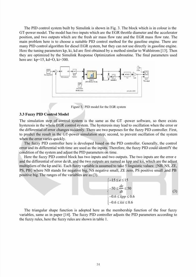
The PID control system built by Simulink is shown in Fig. 3. The block which is in colour is the
GT-power model. The model has two inputs which are the EGR throttle diameter and the accelerator
position, and two outputs which are the fresh air mass flow rate and the EGR mass flow rate. The
main problem here is to choose a suitable PID control method for the gasoline engine. There are
many PID control algorithm for diesel EGR system, but they can not use directly in gasoline engine.
Here the tuning parameters kp, ki, kd are first obtained by a method similar to Wahlstrom [13]. Then
they are optimized by the Simulink Response Optimization subroutine. The final parameters used
here are: kp=15, kd=O, ki=300.
Figure 3. PID model for the EGR system
3.3 Fuzzy PID Control Model
The simulation step of control system is the same as the GT -power software, so there exists
hysteresis in the whole EGR control system. The hysteresis may lead to oscillation when the error or
the differential of error changes suddenly. There are two purposes for the fuzzy PID controller. First,
to predict the result in the GT-power simulation step; second, to prevent oscillation of the system
when the error varies quickly.
The fuzzy PID controller here is developed based on the PID controller. Generally, the control
error and its differential with time are used as the inputs. Therefore, the fuzzy PID could identifY the
condition of the system and adjust the PID parameters on time.
Here the fuzzy PID control block has two inputs and two outputs. The two inputs are the error e
and the differential of error de/dt, and the two outputs are named as kpp and kii, which are the adjust
multipliers of the kp and ki. Each fuzzy variable is assumed to take 5 linguistic values: {NB, NS, ZE,
PS, PB} where NB stands for negative big, NS negative small, ZE zero, PS positive small ,and PB
positive big. The ranges of the variables are as (3).
15 15
50 50
0.6 0.6
0.6 0.6
e
de
dt
kpp
kii
− ≤ ≤⎧⎪⎪− ≤ ≤⎪⎨⎪− ≤ ≤⎪
− ≤ ≤⎪⎩
(3)
The triangular shape function is adopted here as the membership function of the four fuzzy
variables, same as in paper [14]. The fuzzy PID controller adjusts the PID parameters according to
the fuzzy rules, here the fuzzy rules are shown in table 1.
34

8/12/2019 A Fuzzy PID Controller for Exhaust Gas Recirculation System (2)
http://slidepdf.com/reader/full/a-fuzzy-pid-controller-for-exhaust-gas-recirculation-system-2 4/7
Table 1 The Fuzzy Rules
kpp,kiie
NB NS ZE PS PB
de/dt
NB
NS
ZE
PS
PB
NB,NB
NS,NB
PS,NB
NS,NB
NB.NB
NS,NB
NS,NB
ZE,NS
ZE,NS
NS,NS
ZE,NB
ZE,NB
ZE,ZE
ZE,PS
ZE,PB
PS,NS
ZE,NS
NS,ZE
NS,NS
PS,NS
PB,NB
PS,NB
NB,PS
NS,NB
PB,NB
The EGR fuzzy PID control system constructed by Simulink is shown in Fig. 4. It can be seen
that the fuzzy logic controller block adjusts the PID parameters by (4).
(1 )
(1 )
KP kp kpp
KI ki kii
= +⎧⎨
= +⎩ (4)
Where KP is the proportional factor of the fuzzy PID control, and KI is the integral factor.
Figure 4. fuzzy PID model for the EGR system
4. The Comparison of the Two Control Strategies
4.1 Response Characteristics Analysis of the Step Signal
Traditionally step signal is used to test the response time, maximum overshoot and convergence time
of the system. Here a simple step signal is set up when the speed of the engine is 2000 rpm. The
EGR system is closed at first, and then the EGR ratio is set to 15%. The response of the PID
controller is shown in Fig. 5.
Figure 5. The response characteristics of the PID controller to a step signal
35

8/12/2019 A Fuzzy PID Controller for Exhaust Gas Recirculation System (2)
http://slidepdf.com/reader/full/a-fuzzy-pid-controller-for-exhaust-gas-recirculation-system-2 5/7
As we can see, both of the two systems take only 0.05s to reach the target EGR value and
converge within 0.5s. But the difference of the two systems is also obvious. The maximum overshoot
of the PID system is 22.51 % while that of the fuzzy PID is only 4.67%. The fuzzy PID controller
decreases the maximum overshoot of the system while not prolonging the convergence time.
4.2 Tracking Characteristics of Real Time Signals
The working conditions of gasoline engine vary from time to time, which requires the EGR
controller to follow the change quickly without any oscillation. Fig. 6 shows how the two controllers
respond to the real time signals. The two control strategies can follow the tracks of the variational
objective when the differential of target signal is not O. But when the differential of the target signal
is 0, the PID control system could not avoid a short oscillation, while the fuzzy PID control system
can follow the target all the same.
4.3 Performance of Anti-interference
Anti-interference characteristic is one of the basic characteristics to a real time control system. In the
gasoline engine, the interferences may come from the changing of the accelerator position, the
pressure wave and the instability of the sensors. A good controller can adjust the EGR throttle
rapidly to ensure that the EGR ration would not change too much. Fig. 7 (b) shows the performance
of the two control systems with a interference signal (a) adding to the two systems.
Figure 6. Tracking characteristics of real time signals
(a) (b)
Figure 7. The anti-interference performance of the two controllers (b) under the interference of the accelerator throttleangle (a)
The connection of the interferences signal using in Fig.7 (a) and the EGR control system can be
seen in Fig. 4. It should be noted that the two control systems can return to original position quickly,
but obviously the amplitude of fuzzy PID control system is smaller than that of PID control system.
36

8/12/2019 A Fuzzy PID Controller for Exhaust Gas Recirculation System (2)
http://slidepdf.com/reader/full/a-fuzzy-pid-controller-for-exhaust-gas-recirculation-system-2 6/7

8/12/2019 A Fuzzy PID Controller for Exhaust Gas Recirculation System (2)
http://slidepdf.com/reader/full/a-fuzzy-pid-controller-for-exhaust-gas-recirculation-system-2 7/7
[12] Yoshio Yoshioka, Yasuharu Tabata and Hayato Hatakenaka, "Automatic Control Method of
NO Removal by a Combination of Ozone Injection and Exhaust Gas Recirculation". IEEE
TRANSACTIONS ON INDUSTRY APPLICATIONS, MAY/JUNE 2010, 46(3): 1166-1174.
[13] J. Wahlstrom, L. Eriksson and L. Nielsen, "PID controllers and their tuning for EGR and VGT
control in diesel engines", IFAC World Congress, Prague, Czech Republic, 2005.
[14] Hu Han-hui and Tan Qing. "Decoupling fuzzy PID control for magnetic suspended table",
Journal of Central South University (Science and Technology), Aug 2009, 40(4) 963-968.
38