A flow field study of the interaction between a centrifugal compressor impeller and two different...
13
345 A flow field study of the interaction between a centrifugal compressor impeller and two different volutes Y Dai 1 , A Engeda 1∗ , M Cave 2 , and J-L Di Liberti 2 1 Turbomachinery Lab, Department of Mechanical Engineering, Michigan State University, Michigan, USA 2 Solar Turbines Inc., San Diego, California, USA The manuscript was received on 14 January 2009 and was accepted after revision for publication on 22 July 2009. DOI: 10.1243/09544062JMES1522 Abstract: The interaction between an impeller with one large and one small overhung volute was investigated by both computational fluid dynamics simulation and experimental methods. The large volute was mainly generated by increasing the small volute axial length. The computational model, with k–ε turbulence model and wall function, has been used to predict the internal flow of both volutes. The effect of volute tongue on the flow in the impeller was analysed at off-design conditions. The flow structure in the volutes was also investigated in detail. The performance test of the two configurations was carried out in the aero test facility at Solar Turbines Inc. A good agreement between experimental data and numerical simulation results was found on both the whole compressor stage performance and the impeller performance. The largest deviation is close to 10 per cent for the compressor stage performance prediction at high mass flowrate only. Keywords: centrifugal compressor, volute flow, effect of volute 1 INTRODUCTION A volute is an important component whose function is to collect the flow from the periphery of a diffuser and deliver it to the outlet pipe. Even in low-speed com- pressor and pump applications where simplicity and low cost count for more than efficiency, it is the diffuser not the volute that is omitted. Nowadays, one popu- lar design objective is to achieve a uniform pressure distribution at the volute inlet because the circumfer- ential pressure distortion that occurs inside the volute would propagate upstream and cause flow fluctua- tions in the impeller. This would create an efficiency drop in the whole compressor stage. Recently, stud- ies on volute–impeller interaction have attracted more and more interest. Elholm et al.[1] investigated the three-dimensional (3D) velocity distributions in two different cross-sections of a pump volute by means of laser doppler velocimetry (LDV). They found that the ∗ Corresponding author: Turbomachinery Lab, Department of Mechanical Engineering, Michigan State University, 2555 EB, East Lansing, MI 48824, USA. email: [email protected] leakage flows around the tongue region could increase or decrease the flow in the volute and therefore influ- ence the circumferential pressure distribution. Ayder et al.[2, 3] measured the variations of total and static pressure distribution at the vaneless diffuser exit and at different volute cross-sections in a centrifugal com- pressor with an elliptic-shaped volute. They concluded that the flow in volutes is affected more by the losses in the core than by the wall boundary layer. Bound- ary layer blockage can be neglected. Hence, Euler solver, not the Navier–Stokes equation, with an added second-order dissipation and wall shear force, was employed in their simulation. The simulation depar- tures were believed to be from the complexity of volute geometry and test data uncertainty. Hillewaert andVan den Braembussche [4] simulated the volute–impeller interaction using an unsteady flow calculation in the impeller and a time-averaged flow calculation in the volute. There was no average total pressure reduction found in this calculation method and was explained as a no-mix-out in the diffuser, contrarily to the rapid mixing at the impeller exit. Again, the authors used the same methods as what Ayder et al. used in order not to solve Navier–Stokes equations. The simulation results gave a correct trend for the overall performance JMES1522 Proc. IMechE Vol. 224 Part C: J. Mechanical Engineering Science
description
Centrifugal compressor volute
Transcript of A flow field study of the interaction between a centrifugal compressor impeller and two different...
345
A flow field study of the interaction betweena centrifugal compressor impeller andtwo different volutesY Dai1, A Engeda1∗, M Cave2, and J-L Di Liberti2
1Turbomachinery Lab, Department of Mechanical Engineering, Michigan State University, Michigan, USA2Solar Turbines Inc., San Diego, California, USA
The manuscript was received on 14 January 2009 and was accepted after revision for publication on 22 July 2009.
DOI: 10.1243/09544062JMES1522
Abstract: The interaction between an impeller with one large and one small overhung volute wasinvestigated by both computational fluid dynamics simulation and experimental methods. Thelarge volute was mainly generated by increasing the small volute axial length. The computationalmodel, with k–ε turbulence model and wall function, has been used to predict the internal flowof both volutes. The effect of volute tongue on the flow in the impeller was analysed at off-designconditions. The flow structure in the volutes was also investigated in detail.
The performance test of the two configurations was carried out in the aero test facility at SolarTurbines Inc. A good agreement between experimental data and numerical simulation resultswas found on both the whole compressor stage performance and the impeller performance. Thelargest deviation is close to 10 per cent for the compressor stage performance prediction at highmass flowrate only.
Keywords: centrifugal compressor, volute flow, effect of volute
1 INTRODUCTION
A volute is an important component whose function isto collect the flow from the periphery of a diffuser anddeliver it to the outlet pipe. Even in low-speed com-pressor and pump applications where simplicity andlow cost count for more than efficiency, it is the diffusernot the volute that is omitted. Nowadays, one popu-lar design objective is to achieve a uniform pressuredistribution at the volute inlet because the circumfer-ential pressure distortion that occurs inside the volutewould propagate upstream and cause flow fluctua-tions in the impeller. This would create an efficiencydrop in the whole compressor stage. Recently, stud-ies on volute–impeller interaction have attracted moreand more interest. Elholm et al. [1] investigated thethree-dimensional (3D) velocity distributions in twodifferent cross-sections of a pump volute by means oflaser doppler velocimetry (LDV). They found that the
∗Corresponding author: Turbomachinery Lab, Department of
Mechanical Engineering, Michigan State University, 2555 EB, East
Lansing, MI 48824, USA.
email: [email protected]
leakage flows around the tongue region could increaseor decrease the flow in the volute and therefore influ-ence the circumferential pressure distribution. Ayderet al. [2, 3] measured the variations of total and staticpressure distribution at the vaneless diffuser exit andat different volute cross-sections in a centrifugal com-pressor with an elliptic-shaped volute.They concludedthat the flow in volutes is affected more by the lossesin the core than by the wall boundary layer. Bound-ary layer blockage can be neglected. Hence, Eulersolver, not the Navier–Stokes equation, with an addedsecond-order dissipation and wall shear force, wasemployed in their simulation. The simulation depar-tures were believed to be from the complexity of volutegeometry and test data uncertainty. Hillewaert andVanden Braembussche [4] simulated the volute–impellerinteraction using an unsteady flow calculation in theimpeller and a time-averaged flow calculation in thevolute. There was no average total pressure reductionfound in this calculation method and was explainedas a no-mix-out in the diffuser, contrarily to the rapidmixing at the impeller exit. Again, the authors usedthe same methods as what Ayder et al. used in ordernot to solve Navier–Stokes equations. The simulationresults gave a correct trend for the overall performance
JMES1522 Proc. IMechE Vol. 224 Part C: J. Mechanical Engineering Science

346 Y Dai, A Engeda, M Cave, and J-L Di Liberti
except at low mass flowrate. Gu et al. [5] obtainedsatisfactory results by solving Navier–Stokes equationswith the k–ε turbulence model and wall function builtin TASCFlow. This article limits the discussion to theflow axial distortion since the exit flow at the impellerexit was averaged circumferentially.
For the study presented here, two flat-top overhungvolutes with the same impeller were investigated bysolving Navier–Stokes equations. The k–ε turbulencemodel and wall function built in TASCFlow are alsoused in this study. See reference [6] for more details.As far as the code methodology and validation appliedon compressors, see references [7] to [9]. Attentionwas focused on the effect of the volute tongue, vol-ume and cross-section channel curve on the impellerand compressor performance. The first part of thisarticle compares the computational fluid dynamics(CFD) results with experimental data in order to vali-date the simulation model. The second part is mainlyon the effect of the volute tongue on different impellerpassages. The last part describes the flow structure involutes.
2 COMPRESSOR GEOMETRY
The shrouded impeller (shown in Fig. 1) has 13 bladeswith −60◦ of blade angle from the radial. The tip–diameter ratio (b4/D4) of the impeller is 0.036. Thegeometry of the compressor is given in Fig. 2.The vane-less diffuser is pinched 40 per cent, which means thepinch ratio (b5/b4) is 0.60. The radius ratio of R5/R4
is 1.1. The radius ratio of R6/R4 of the small voluteconfiguration is 2.0. The width of the vaneless diffuseris the same for both configurations. The large volutewas generated mainly by increasing the axial posi-tion and decreasing the diffuser height of the smallvolute. The tongue positions of the two volutes startat zero azimuth angle (see Fig. 2). The two volute con-tours at tongue position (station 7) are shown in Fig. 3.Volute wall has been divided into four parts to facili-tate the later discussion. There is no obvious borderbetween the adjacent walls, for example, the border
Fig. 1 Shrouded impeller
Fig. 2 Compressor configuration
Fig. 3 Volute geometry at station 7
Proc. IMechE Vol. 224 Part C: J. Mechanical Engineering Science JMES1522

Interaction between a centrifugal compressor impeller and two different volutes 347
between the outer wall and the shroud wall. Thesedefinitions of walls are only qualitative. Circumferen-tially, the cross-sectional area ratio of the two volutesis the same as the ratio in the tongue position. Forthe exit cone part, the area ratio of the two volutesat the same circumferential position is also the same.Hence, the differences between the two configurationsare that the large volute has a larger volume and big-ger throat, and the vaneless diffuser length is a little bitshorter.
3 COMPUTATIONAL METHOD
3D, compressible, steady flow computations were car-ried out using the commercial computational fluiddynamics code, CFX-TASCflow. This code solves theReynolds averaged Navier–Stokes equations in prim-itive variable form. The k–ε turbulence model wasemployed for these simulations.
‘Wall functions’ were supplied to model the momen-tum and heat transfer processes for turbulent flowsin the near-wall region that makes it feasible to use arelatively coarse grid. The wall function is based ona function of y+, which avoids problems at separa-tion points. The coefficients in the equations beloware determined such that the three equations are con-tinuous in value and first derivative. See reference [6]for more detail
u+ = y+, y+ � 5
u+ = d1y+3 + d2y+2 + d3y+ + d4, 5 � y+ � 30
u+ = 1κ
ln(y+) + C , 30 � y+ � 500 (smooth wall)
where
u+ = ut
uτ
κ and C are constants depending on wall roughness(κ is the von Karman constant for smooth walls).
The impeller grid was generated from the commer-cial impeller grid generator, TASCgen. A FORTRANcode was written for the generation of the input filesfor TASCgrid that was used to generate the volute anddiffuser meshes. The volute meshes are of butterflysection (see Fig. 4) so as to reduce the grid skewnessbecause bad grid skewness may cause convergenceproblems. The control points in each circumferentialvolute cross-section create the butterfly core individu-ally. In addition to the control points, the code can alsodistribute grid points along the volute and diffuser sur-faces and interior areas as well, though the distributionis based on the positions of the control points. Theversatility to create control and grid points freely foreach circumferential cross-section of volute and dif-fuser not only facilitates the structure grid generation
Fig. 4 Volute butterfly section and grid distribution(black dots are control points)
but also improves the grid quality that in turn makesthe convergence easier and faster.
Because the impeller and volute meshes are gener-ated separately, and one side is in a rotating frame ofreference and the other in a stationary frame of ref-erence, it is important to apply a frame change andallow a non-matching grids connection at the interfacein between. The multiple frame of reference capabil-ity in CFX-TASCflow3D uses ‘stage’ and ‘frozen’ rotorconcepts (Fig. 5) to have the job done.
In the stage rotor, it is assumed that all the otherpassages of the impeller grid experience the sameflow as in the impeller passage shown in Fig. 5(a).The impeller exit flow is averaged circumferentially.Therefore, only one passage of the impeller needs tobe modelled and the periodic condition needs to bedefined for this impeller passage. In the frozen rotor,Fig. 5(b), all impeller passages are simulated together.The two frames of reference connect in such a waythat they each have a fixed relative position throughoutthe calculation. If the frame changes the appropriateequation transformations are made. The impeller exitflow is no longer assumed to be uniform and the flowsin each passage are not assumed to be periodic either.Thus, frozen rotor analysis can be used to investi-gate the circumferential variation of the impeller outletflow in steady state. The transient effects at the inter-face between the impeller and volute are not modelled.However, based on reference [4], this should not be aconcern. Also, there is no need to keep the impellergrid number and shape the same as the diffuser gridnumber and shape at the connection interface. Formore details on the stage and frozen rotor concepts,see reference [6]. In this study, all the results are fromthe ‘frozen rotor’ concept.
For each impeller passage, the grid size was 32 851points. Hence the whole impeller had 427 063 points.The size of the volute and diffuser was 231 710 points.
JMES1522 Proc. IMechE Vol. 224 Part C: J. Mechanical Engineering Science

348 Y Dai, A Engeda, M Cave, and J-L Di Liberti
Fig. 5 Three-dimensional view of the discretized flow domain
Another coarse mesh size is 235 248 points for thewhole impeller (18 096 points for each passage) and145 535 points for the volute and diffuser. The resultsfrom the two different meshes are less than 0.5 percent based on the compressor efficiency and pressureratio computation. The flow patterns in both mesh set-tings also exhibit the same trend. Hence, the solutionis believed as grid-independent.
As mentioned above, for the smooth wall and k–ε
turbulence model, the software recommends that they+ value needs to be less than 500. The maximum y+
value from this mesh setting in the worst case wasabout 400 in a very small region that well fits in therecommended range.
The inflow boundary conditions were based on thetotal pressure, total temperature, inflow velocity direc-tion, turbulence intensity, and turbulence eddy lengthscale, where the turbulence intensity is 5.0 per centand the turbulence eddy length scale is 0.15 mm.Based on experience, with the standard k–ε turbulencemodel and wall function turned on, the inlet turbu-lence only has a small effect on the final solution aslong as the first grid point is in the logarithmic sublayerof boundary layers. In this study, the inlet averaged y+
value is about 72 and the minimum y+ value is stilllarger than 30, which guarantee that the first nodes getinto the log-law region while still staying away fromthe viscous sublayer where the software’s assumptionused in the derivation of the k and ε equations willno longer be fully valid (when y+ value is <30). Themass flowrate was used as the outlet boundary con-dition. Experience shows that this kind of boundarycondition is very robust in the simulation.
The calculation was considered to be convergedwhen the non-dimensionalized maximum residualsare reduced to 1.0 × 10⁻⁴, and it was also con-firmed that the final solutions were unchanged afterfurther iterations reduced these errors to 1.0 × 10⁻⁵ or1.0 × 10−6.
4 TEST FACILITY AND EXPERIMENTAL SET-UP
The Aero Test Facility (ATF), located at Solar TurbinesInc., is a research facility with specialized instrumen-tation capability. Figure 6 is the sketch of the testfacility. The compressor is driven by a 100 HP vari-able speed electric motor coupled to a gear box.The piping maximum allowable pressure is 150 psia.The mass flowrate was measured by a venturi thatwas located between the heat exchanger and com-pressor inlet, and controlled by three parallel valvesdownstream of the discharge flange. The inlet tem-perature was maintained by adjusting the coolingwater flowrate of the heat exchanger upstream of thecompressor inlet. The entire test article and the closed-loop piping are indoors. Air was the test gas for allthe tests even though the ATF is capable of usingother gases. Temperatures are determined by usingan signal conditioning extension for instrumentation(SCXI) temperature system with type T thermocou-ples. Calibration coefficients are developed to provide
Fig. 6 A sketch of the test facility
Proc. IMechE Vol. 224 Part C: J. Mechanical Engineering Science JMES1522

Interaction between a centrifugal compressor impeller and two different volutes 349
an accuracy of ±0.2 ◦F in the anticipated temperaturerange. Pressures are acquired with a Pressure SystemsInc. (PSI) 8400 system. All measured pressures are cali-brated on-line during the test and up to 256 pressurechannels may be monitored. The data acquisition sys-tem (DAS) is proprietary software designed by Solar.The DAS obtains all measurements data and performson-line data reduction.
The maximum test uncertainty of the head for thistest is +0.21 to −0.42 per cent and the uncertaintyof efficiency is +0.23 to −0.45 per cent. As the testaccuracy is pretty good, the small uncertainties werenot plotted in the results.
In this test, the compressor stage was insulatedand equipped with four total pressure probes, fourstatic pressures, and four total temperatures at thecompressor inlet and discharge port. After complet-ing a flange–flange test, Kiel probes were installedat three different pinch positions (V probe is at 72◦,the N probe at 180◦, and the F probe at 288◦. SeeFig. 2) at a fixed angle. The Kiel probe installationfixed angle is used for an accurate measurement of thetotal pressure. Hence the impeller performance can beestimated from the measurement of the probes at theposition R5, which is only 1.1 times that of the R4.
Flow enters the compressor through an inlet guidevanes (IGV). The IGV deswirls the inlet flow, providinga flow with zero swirl to the impeller eye.
Performances at several rotational speeds weremeasured. However, only the 19 240 r/min speed ispresented here. References [10] and [11] give moreinformation about the ATF and the experimentalset-up.
5 RESULTS AND DISCUSSION
5.1 Comparison of simulation and test data
The design point and three off-design conditions wererun for both volute configurations. The design pointwas always the first point to run in each simulation.Thereafter, the results of the design point were usedas the initial guesses for the off-design conditions. Forall the simulations, the machine Mach number is 0.66(19 240 r/min).
Figure 7 shows the whole compressor performance.First, it can be seen that the CFD simulation hassatisfactory results except at high mass flow. Second,because the CFD simulation did not incorporate theleakage flow in the labyrinth between the shroud outerwall and the machine case, and the ‘smooth’ wall wasan assumption in the simulation, the CFD curves arealways above the experimental data curves. It canalso be noted that, for the small volute, the differ-ence between the CFD points and experimental pointsbecome bigger and bigger from low mass flow to highmass flow. But, for the large volute, the difference is
Fig. 7 Compressor performance
almost a constant. Since the leakage flow is alwaysthere, this might be because the surface roughness hasmore effect in the small volute. Fourth, the small voluteperformance is better when the normalized flow coef-ficient is lower than 0.86; the profit lies on the largevolute if the normalized flow coefficient is bigger thanthis value. The same cross-point is around 1.0 in theCFD results.
Fig. 8 Impeller performance
Fig. 9 Compressor efficiency
JMES1522 Proc. IMechE Vol. 224 Part C: J. Mechanical Engineering Science
350 Y Dai, A Engeda, M Cave, and J-L Di Liberti
Because the three probes (V , N , and F ) wereinstalled on the pinch position circumferentially in thetest rig as mentioned above, the performance from theimpeller inlet to the pinch position was selected asthe estimation of the impeller performance in order tocompare with the test data. The comparison is shownin Fig. 8. The experimental data are averaged values ofthe three probes. It can be seen that the experimentaldata of the two volutes are pretty close with the excep-tion of slight difference at low mass flow. The CFDresults match the experimental data very well through-out the flow range. This indicates that the volute designdoes not affect the impeller performance.
Comparing Figs 7 and 8, it can be seen thatthe surface roughness almost has no effect on theimpeller performance, but has some effects on thewhole compressor performance. ‘Smooth’ wall wasan assumption in the CFD simulation and this is ingood agreement with the conclusion in reference [12]
that claimed ‘impeller flow is not affect by the volutesurface roughness’.
The flange–flange (from stations 1 to 8) isentropicefficiency is presented in Fig. 9. From this figure, wecan see that simulation is only in qualitative agree-ment with the experimental ones at high mass flow,namely, simulation can only predict the efficiency‘trend’. When the flow coefficient is 1.25, the largevolute improved the efficiency significantly, whichhas also been proven by test data. At low mass flow,the efficiency drop of the larger volute is kind ofsmall. The discrepancy at high mass flow is from themodelling method that neglects the losses incurredin the real situation as the flow mixed betweenthe impeller and diffuser is not modelled. Here, the‘big’ difference between simulation and test is alsopartly from the reference efficiency used for thenormalization that is more than 15 per cent lessthan 1.
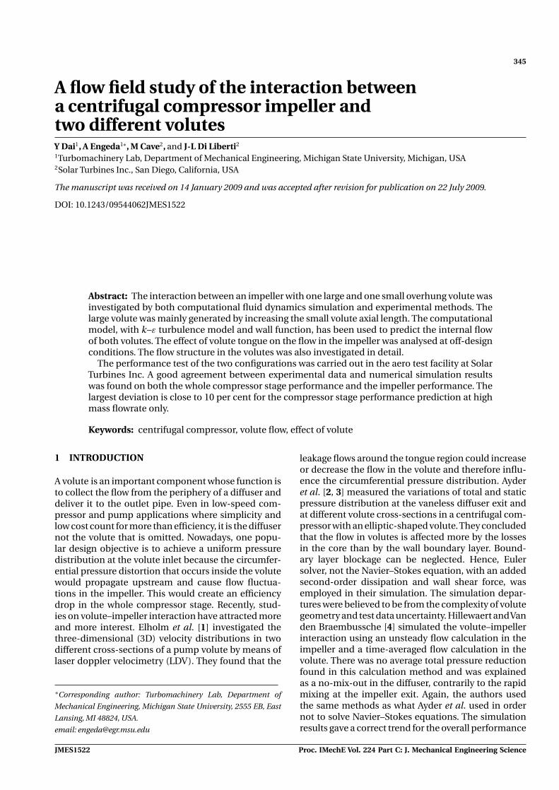
Fig. 10 Static pressure at high mass flow
Proc. IMechE Vol. 224 Part C: J. Mechanical Engineering Science JMES1522

Interaction between a centrifugal compressor impeller and two different volutes 351
5.2 Flow analysis in the impeller
Figure 10 represents the static pressure distributionbetween blades; part (a) is nearest to the tongue andpart (b) is farthest from the tongue. The static pres-sure at station 2 near the tongue region (Fig. 10(a))shows a gradient in the hub-to-shroud direction dueto the high centrifugal acceleration at high mass flow.At this station, the pressure on the suction side (SS)is higher than that on the pressure side (PS). Hencethe impeller has a negative loading on the leadingedge at high mass flow. And the low-pressure region islocated on the shroud–pressure-side corner. At station3, the pressure gradient is no longer hub-to-shroud.Moreover, positive blade loading occurs at this station,and the low-pressure region changes to the shroud–suction-side corner. At station 4, the pressure exhibitsan almost symmetrical distribution. The low-pressureregion is on both the shroud–suction-side and hub–pressure-side corners. No matter in which station, thepressure in the configuration with the large volute atthe same location is lower than the pressure with thesmall volute. The largest adverse pressure gradient ofthe static pressure between different stations is onthe shroud–pressure-side corner at station 3, whichis more than two times than all other corners at least.This pressure rise occurs as the fluid turns through thebend when the relative velocity is reduced.
The position farthest from the tongue is shown inFig. 10(b). The impeller also has a negative loadingat station 2 and the pressure gradient also becomespressure-to-suction direction at stations 3 and 4. But,it can be seen that the two volutes exhibit almost thesame trend and magnitude in all the three stations.
Hence, the tongue effect can be neglected around thislocation.
Since the pressure gradient is pressure-to-SS on sta-tions 3 and 4, the midspan pressure distributions atthese two stations should represent the field pres-sure distribution of the whole station. Among the 13blades, the two extreme curves, minimum and maxi-mum pressure curves, have been given in Fig. 11for each configuration. For the large volute configu-ration, the minimum pressure distribution betweenadjacent blades is nearest to the tongue position; themaximum pressure distribution is between 277◦ and305◦. For the small volute, the phenomenon reversed,the maximum pressure distribution is nearest to thetongue position; the minimum pressure distributionis between 277◦ and 305◦. The minimum pressure dis-tributions for both configurations are almost the same.The discrepancy between maximum curves becomesbigger when the flow goes to the impeller exit, andthe small volute configuration has a wider pressuredistribution range, which means a more non-uniformpressure distribution circumferentially. Therefore, athigh mass flow, the tongue position gives rise to amore severe pressure distortion in blades in smallvolute configuration, and one extreme is always atthe nearest tongue position; another extreme is alwaysaround 290◦, i.e. upstream of the tongue. The distor-tion between blades is caused by the distortion involute.
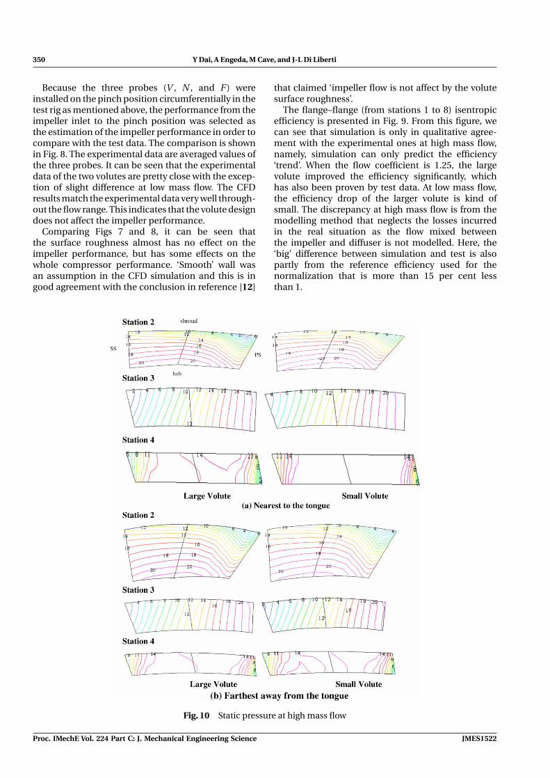
At low mass flow, the static pressure gradient at sta-tion 2 is no longer hub-to-shroud direction (Fig. 12).At stations 3 and 4, the trends at low mass flow are thesame as the trends at high mass flow cases. Far awayfrom the tongue, both configurations exhibit almost
1
1.02
1.04
1.06
1.08
1.1
1.12
1.14
1.16
azimuth angle
P/P
ref
nearest tongue with large volutenearest tongue with small volute277-305 deg with large volute277-305 deg with small volute
SS PS
(a) station 3
1.18
1.19
1.2
1.21
1.22
1.23
azimuth angle
P/P
ref
nearest tongue with large volutenearest tongue with small volute277-305 deg with large volute277-305 deg with small volute
SS PS
(b) station 4
Fig. 11 Midspan static pressure distribution at high mass flow
JMES1522 Proc. IMechE Vol. 224 Part C: J. Mechanical Engineering Science
352 Y Dai, A Engeda, M Cave, and J-L Di Liberti
Fig. 12 Static pressure at low mass flow
the same pressure distribution. Nearest to the tongueposition, the tendency is the same, but the pressureamong blades with the large volute is a little bit smallerthan the pressure among blades with the small voluteat the same position.
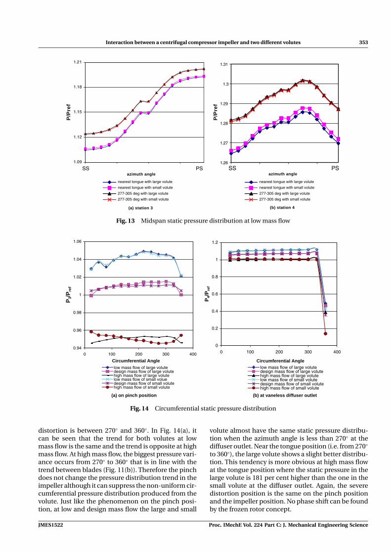
Figure 13 shows the midspan pressure distribu-tion at stations 3 and 4 at low mass flow based onthe same reason mentioned above. It can be seenthat the minimum pressure distribution is nearest tothe tongue position for both volutes this time. Themaximum pressure distribution is between 277◦ and305◦ for both configurations. At low mass flow, thetongue effect on the pressure distribution influencesthe minimum pressure curves more (close to tongue),and only very little effect on other circumferential
positions. It seems that the small volute causes lesssevere pressure distortion among the blades becausethe ranges of small volute cases between maximumand minimum pressure curves are smaller at low massflow.
Comparing Figs 11 and 13, it can be concluded thatthe distortion in different impeller passages at lowmass flow is severer than the one at high mass flow.
5.3 Flow analysis in the vaneless diffuser
Figure 14 shows mass averaged pressure value dis-tribution on the pinch position (Fig. 14(a)) and atthe diffuser outlet (Fig. 14(b)). The severest pressure
Proc. IMechE Vol. 224 Part C: J. Mechanical Engineering Science JMES1522
Interaction between a centrifugal compressor impeller and two different volutes 353
1.09
1.12
1.15
1.18
1.21
azimuth angle
P/P
ref
SS PS
(a) station 3
1.26
1.27
1.28
1.29
1.3
1.31
azimuth angle
P/P
ref
nearest tongue with large volute
nearest tongue with small volute
277-305 deg with large volute
277-305 deg with small volute
nearest tongue with large volute
nearest tongue with small volute
277-305 deg with large volute
277-305 deg with small volute
SS PS
(b) station 4
Fig. 13 Midspan static pressure distribution at low mass flow
0.94
0.96
0.98
1
1.02
1.04
1.06
0 100 200 300 400
Circumferential Angle
P3/
Pre
f
low mass flow of large volutedesign mass flow of large volutehigh mass flow of large volutelow mass flow of small voluedesign mass flow of small volutehigh mass flow of small volute
(a) on pinch position
0
0.2
0.4
0.6
0.8
1
1.2
0 100 200 300 400
Circumferential Angle
P4/
Pre
f
low mass flow of large volutedesign mass flow of large volutehigh mass flow of large volutelow mass flow of small volutedesign mass flow of small volutehigh mass flow of small volute
(b) at vaneless diffuser outlet
Fig. 14 Circumferential static pressure distribution
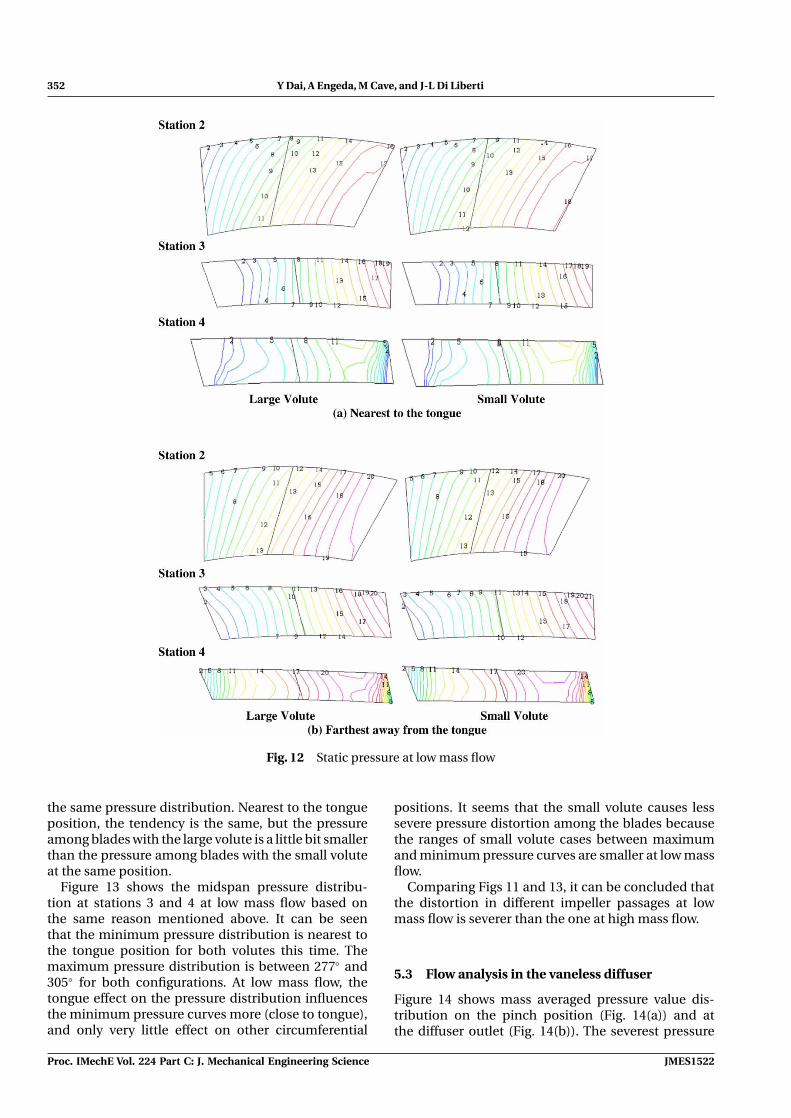
distortion is between 270◦ and 360◦. In Fig. 14(a), itcan be seen that the trend for both volutes at lowmass flow is the same and the trend is opposite at highmass flow. At high mass flow, the biggest pressure vari-ance occurs from 270◦ to 360◦ that is in line with thetrend between blades (Fig. 11(b)). Therefore the pinchdoes not change the pressure distribution trend in theimpeller although it can suppress the non-uniform cir-cumferential pressure distribution produced from thevolute. Just like the phenomenon on the pinch posi-tion, at low and design mass flow the large and small
volute almost have the same static pressure distribu-tion when the azimuth angle is less than 270◦ at thediffuser outlet. Near the tongue position (i.e. from 270◦
to 360◦), the large volute shows a slight better distribu-tion. This tendency is more obvious at high mass flowat the tongue position where the static pressure in thelarge volute is 181 per cent higher than the one in thesmall volute at the diffuser outlet. Again, the severedistortion position is the same on the pinch positionand the impeller position. No phase shift can be foundby the frozen rotor concept.
JMES1522 Proc. IMechE Vol. 224 Part C: J. Mechanical Engineering Science
354 Y Dai, A Engeda, M Cave, and J-L Di Liberti
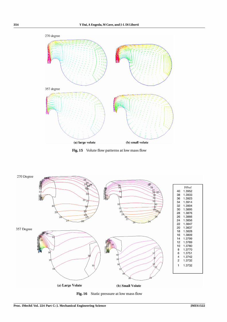
Fig. 15 Volute flow patterns at low mass flow
Fig. 16 Static pressure at low mass flow
Proc. IMechE Vol. 224 Part C: J. Mechanical Engineering Science JMES1522

Interaction between a centrifugal compressor impeller and two different volutes 355
Fig. 17 Total pressure at low mass flow
5.4 Flow structure in volutes
It was well known that swirling flow exists in the volute.Gu et al. [5] indicated that the more energy loss at highmass flow is from the exist of the twin vortex down-stream of the tongue, which is induced by the lowradial velocity at the shroud side; at low mass flow,more loss is from the recirculation upstream of thetongue that is caused by the fluid at the hub side andcannot exit the volute. According to the analysis in theimpeller, the zone between blades that is affected mostby the volute is from 270◦ to 360◦. Therefore the com-parison of the swirling flow of the two volutes at lowmass flow in this range is shown in Fig. 15. Ayder andVan den Braembussche [3] presented that the secondflow existed in the inner-hub wall corner in his rect-angular volute. Two volute cross-sections, 270◦ and357◦, are selected to be shown here. It can be seenthat at low mass flow the twin vortex exists at 357◦
(upstream, not downstream of the tongue) in bothvolutes, and the position is around the interface of theinner-shroud wall. At 270◦, the twin vortex occurs onlyin the large volute, not in the small volute. No twinvortex flow is found for both volutes at high mass flow(not shown here) because of the large radial velocityat the volute inlet. This proves that the twin vortex isnot relative to how big the mass flow is. Gu et al. [5]found that the twin vortex only existed at high massflow. It strongly depends on the flow structure in thevolute that is affected by the volute channel curvatureand the leakage around the tongue region.
The static and total pressure distributions at lowmass flow are presented in Figs 16 and 17, respectively.In the large volute, the pressure ranges from number26 to 36 at 270◦ and from number 33 to 37 at 357◦,which is more uniform. The same thing happens inthe small volute. Comparison of the two volutes at 270◦
shows that the pressure gradient is bigger in the smallvolute. This is because the sharp volute cross-sectioncurvature is ‘strong’ enough to make the pressure gra-dient in the inner–outer wall direction. This is helpfulto suppress the secondary flow – twin vortex. Aroundthe tongue (i.e. at 357◦), both volutes curvature can-not keep this pressure gradient, which is the reasonwhy the twin vortex occurs from the shroud-inner wallinterface. Hence it would be a good idea to change thelarge volute cross-section curvature from 270◦ basedon the small volute shape to get a better performanceat low mass flow since no twin vortex occurs in thesmall volute at low mass flow.
6 CONCLUSIONS
The interaction between one impeller and two differ-ent volutes is investigated by computing 3D Navier–Stokes equations. The frozen rotor concept built in thecommercial code, TASCFlow, is used in the simulation.The following conclusions may be drawn based on theanalysis above.
Although the whole compressor performance will beaffected by different volute designs, the volute designs
JMES1522 Proc. IMechE Vol. 224 Part C: J. Mechanical Engineering Science

356 Y Dai, A Engeda, M Cave, and J-L Di Liberti
investigated here do not affect the impeller perfor-mance (from the impeller inlet to pinch position).
No pressure distortion position shift from the vane-less diffuser outlet to the stations inside the blades wasfound by using the steady-state frozen method.
At high mass flow, negative blade loading was foundin the blade leading edge. The distortion in differentimpeller passages at low mass flow is severer than theone at high mass flow. The same phenomenon can befound on the pinch position.
At high mass flow, the large volute tongue benefitsthe performance more.
For the flat-top overhung volute, the second flowusually starts from the inner-shroud interface, and thesecond flow strongly depends on the volute channelcurvature and the leakage around the tongue region.This phenomenon occurs either at low mass flow orat high mass flow, not only in low mass flow as somereferences indicated.
The extreme pressure values always are locatednearest to the tongue and upstream tongue regions.More attention should be paid to these locationsduring the volute design process.
ACKNOWLEDGEMENT
The authors would like to thank Solar Turbines Incor-porated for supporting this project.
© Authors 2010
REFERENCES
1 Elholm, T., Ayder, E., and Van Den Braembussche, R.Experimental study of the swirling flow in the voluteof a centrifugal pump. ASME J. Turbomach., 1992, 114,366–372.
2 Ayder, E., Van den Braembussche, R., and Brasz, J. J.Experimental and theoretical analysis of the flow ina centrifugal compressor volute. ASME J. Turbomach.,1993, 115, 582–589.
3 Ayder, E. and Van den Braembussche, R. Numericalanalysis of the three-dimensional swirling flow in cen-trifugal compressor volutes. ASME J. Turbomach., 1994,116, 462–468.
4 Hillewaert, K. and Van den Braembussche, R. A. Nume-rical simulation of impeller–volute interaction in cen-trifugal compressor. ASME J. Turbomach., 1999, 121,603–608.
5 Gu, F., Engeda, A., Cave, M., and Di Liberti, J.-L. A nume-rical investigation on the volute/diffuser interaction dueto the axial distortion at the impeller exit. ASME J. FluidsEng., 2001, 123, 475–483.
6 TASCflow User Manual, Version 2.9, 1999, AdvancedEngineering Computing.
7 Flathers, M. B., Bache, G. E., and Rautensberger, R. Anexperimental and computational investigation of flowin a radial inlet of an industrial pipeline centrifugalcompressor. ASME paper 94-GT-134, 1994.
8 Flathers, M. B. and Bache, G. E. Aerodynamicallyinduced radial forces in a centrifugal gas compressor:part 2 – computational investigation. ASME J. Eng. GasTurbines Power, 1999, 121, 725–734.
9 Galpin, P. F., Broberg, R. B., and Hutchinson, B. R. Three-dimensional Navier–Stokes predictions of steady staterotor/stator interaction with pitch change. 1995 (CFD 95 –CFD Society of Canada, Banff, Alberta, Canada).
10 Di Liberti, J.-L. Effect of exit system on the performanceof a low specific speed industrial centrifugal compressorstage. ASME, GT-2003-38570, 1978.
11 David, T., Zhang, D., and Cave, M. Frictional effects on abase and a flow – trimmed impeller of a low specific speedindustrial compressor. ASME GT2006-90998, 1978.
12 Varghese, G., Kumar, T. C., and Rao, Y. V. N. Influ-ence of volutes surface roughness on the performanceof a centrifugal pump. ASME J. Fluids Eng., 1978, 100,473–476.
APPENDIX
Notation
b passage widthCp pressure recoveryD diameterp pressurePS pressure sideR radius from axialSS suction side
η efficiencyφ flow coefficientψ head coefficientω loss coefficient
Subscripts
0 stagnation/atmosphere condition1 impeller inlet2 impeller leading edge3 impeller bend4 impeller tip5 pinch6 diffuser outlet/volute inlet7 volute tongue8 cone outletref reference condition
Proc. IMechE Vol. 224 Part C: J. Mechanical Engineering Science JMES1522

Reproduced with permission of the copyright owner. Further reproduction prohibited without permission.