A Feedforward Amplifier using a Modulation Pilot and Bi...
24
Confidential & Proprietary A Feedforward Amplifier using a Modulation Pilot and Bi-Orthogonal Demodulation for Loop Alignment Control R. Neil Braithwaite Powerwave Technologies IEEE Topical Symposium on Power Amplifiers for Wireless Communications Sept. 2009 1
Transcript of A Feedforward Amplifier using a Modulation Pilot and Bi...
Confidential & Proprietary
A Feedforward Amplifier using a Modulation Pilot and Bi-Orthogonal
Demodulation for Loop Alignment Control
R. Neil Braithwaite Powerwave Technologies
IEEE Topical Symposium on Power Amplifiers for Wireless Communications
Sept. 2009 1
2Confidential & Proprietary
Goal
• Linear amplification of RF signals with large instantaneous bandwidths.– 100 MHz BW planned for LTE-Advanced.
• Pilot-based adaptive feedforward compensation.– Out-of-band pilots measurements are too far away from
the actual signal for large BW’s.
– In-band pilots are acceptable.
• Reasonable cost.– Implement a modulation pilot approach.
3Confidential & Proprietary
Other Goal
• Seeking collaboration.– The math shows potential for LTE.
– Need to build a prototype and test.
• Warning.– This technique has been abandoned numerous times.
4Confidential & Proprietary
Outline
• Background– Feedforward structure for linearization.
• Modulation pilot approach to 2nd loop adaptation.– Review original method proposed by Matz.
– Discuss the short-comings which include biases.
• Propose a new modulation approach.– Use bi-orthogonal demodulation to avoid biases.
• Summary
5Confidential & Proprietary
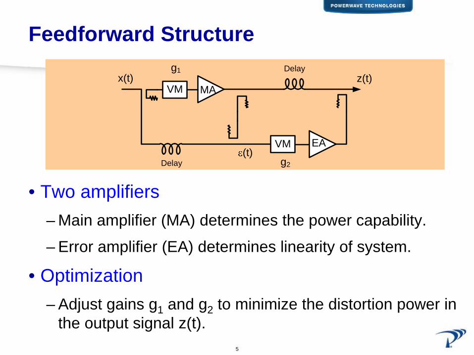
Feedforward Structure
• Two amplifiers– Main amplifier (MA) determines the power capability.
– Error amplifier (EA) determines linearity of system.
• Optimization– Adjust gains g1 and g2 to minimize the distortion power in
the output signal z(t).
x(t) z(t)
g2
MA
EA
g1
VM
VM
(t)
Delay
Delay
6Confidential & Proprietary
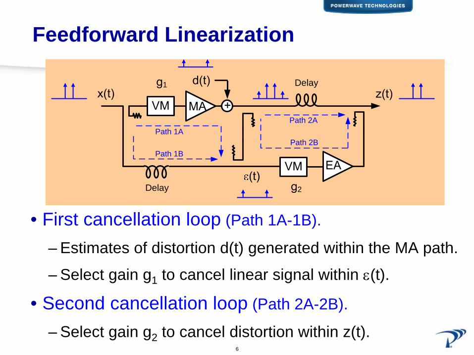
Feedforward Linearization
• First cancellation loop (Path 1A-1B).
– Estimates of distortion d(t) generated within the MA path.
– Select gain g1 to cancel linear signal within ε(t).
• Second cancellation loop (Path 2A-2B).
– Select gain g2 to cancel distortion within z(t).
2
1
Path 1A
Path 1B
Path 2A
Path 2B
Delay
Delay

7Confidential & Proprietary
Modulation Pilot (Matz, US Patent 5491454)
• Modulate 1st loop to control 2nd loop alignment.– Two modulation pilots, γm and γφ
(sine waves, ωm and ωφ
).
– Control (m2 ,φ2 ) by demodulating |z|2 with γm and γφ
.
Inte
grat
e

8Confidential & Proprietary
Modulation Pilot (Matz)
• Amplifier gainMain amplifier + coupling loss: Go. Error amplifier + coupling losses: gEA.
• First loop alignmentg1,static = exp{ m1 + j φ1 }γm and γφ are modulation pilots.g1 = g1,static * exp(γm + j γφ)
9Confidential & Proprietary
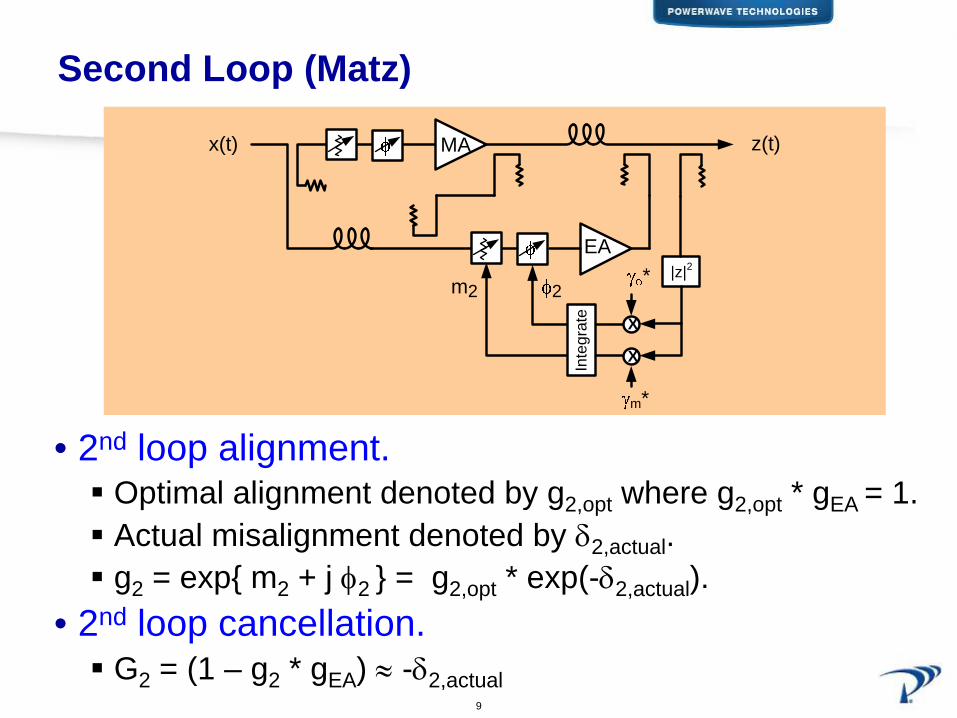
Second Loop (Matz)
• 2nd loop alignment.Optimal alignment denoted by g2,opt where g2,opt * gEA = 1.Actual misalignment denoted by δ2,actual.g2 = exp{ m2 + j φ2 } = g2,opt * exp(-δ2,actual).
• 2nd loop cancellation.G2 = (1 – g2 * gEA) ≈ -δ2,actual
z(t)MA
EA
x(t)
|z|2m2 2
X
X
m*
*
Inte
grat
e
10Confidential & Proprietary
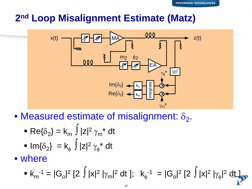
2nd Loop Misalignment Estimate (Matz)
• Measured estimate of misalignment: δ2 .Re{δ2} = km ∫ |z|2 γm* dt
Im{δ2} = kφ ∫ |z|2 γφ* dt• where
km-1 = |Go|2 [2 ∫ |x|2 |γm|2 dt ]; kφ
-1 = |Go|2 [2 ∫ |x|2 |γφ|2 dt ]
z(t)MA
EA
x(t)
|z|2
m2 2
X
X
m*
Im{ 2}
Re{ 2}
*
Inte
grat
e
k
km

11Confidential & Proprietary
FF Output (Matz)
• FF output z(t)z(t) = linear signal + residual in-band pilotz(t) = Go * x(t) + δ2 * (γm + j γφ) * Go * x(t)
• Residual pilot• Modulation index |γm + j γφ
|• 2nd loop misalignment |δ2 |.

12Confidential & Proprietary
Demodulation Offsets (Matz)
Demodulated squared magnitude of FF output∫ |z|2 γm dt = |Go|2 * [ A1 + |δ2|2 * (A2+A6) + Re{δ2} * B1 ]
∫ |z|2 γφ dt = |Go|2 * [ A3 + |δ2|2 * (A4 +A5)+ Im{δ2} * B2 ]
• Offset termsA1 = ∫ |x|2 γm* dt A2 = ∫ |x|2 |γm|2 γm* dt
A3 = ∫ |x|2 γφ* dt A4 = ∫ |x|2 |γφ|2 γφ* dt
A5 = ∫ |x|2 |γm|2 γφ* dt A6 = ∫ |x|2 |γφ|2 γm* dt
• A1 and A3 are the most significant offset terms.B1 = 2 ∫ |x|2 |γm|2 dt > 0 B2 = 2 ∫ |x|2 |γφ|2 dt > 0
13Confidential & Proprietary
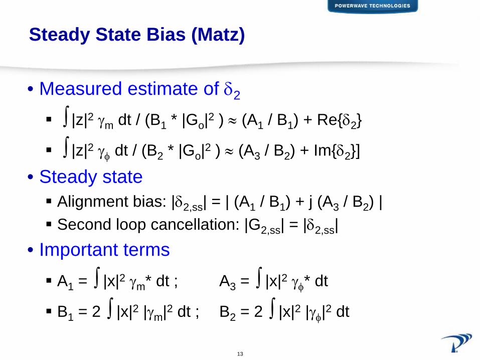
Steady State Bias (Matz)
• Measured estimate of δ2
∫ |z|2 γm dt / (B1 * |Go|2 ) ≈ (A1 / B1) + Re{δ2}
∫ |z|2 γφ dt / (B2 * |Go|2 ) ≈ (A3 / B2) + Im{δ2}]
• Steady stateAlignment bias: |δ2,ss| = | (A1 / B1) + j (A3 / B2) |Second loop cancellation: |G2,ss| = |δ2,ss|
• Important termsA1 = ∫ |x|2 γm* dt ; A3 = ∫ |x|2 γφ* dt
B1 = 2 ∫ |x|2 |γm|2 dt ; B2 = 2 ∫ |x|2 |γφ|2 dt
14Confidential & Proprietary
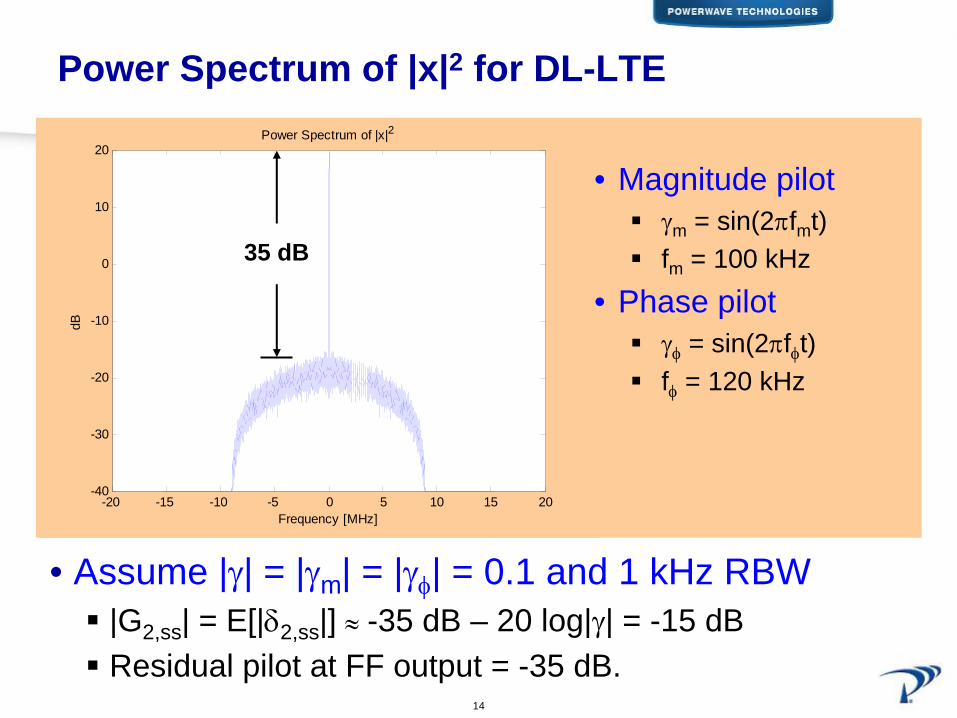
Power Spectrum of |x|2 for DL-LTE
• Assume |γ| = |γm | = |γφ
| = 0.1 and 1 kHz RBW|G2,ss| = E[|δ2,ss|] ≈ -35 dB – 20 log|γ| = -15 dBResidual pilot at FF output = -35 dB.
-20 -15 -10 -5 0 5 10 15 20-40
-30
-20
-10
0
10
20Power Spectrum of |x|2
Frequency [MHz]
dB
35 dB
• Magnitude pilotγm = sin(2πfmt)fm = 100 kHz
• Phase pilotγφ = sin(2πfφt)fφ = 120 kHz
15Confidential & Proprietary
Summary (Matz)
• Steady state offset– Fundamental limitation of Matz approach.– Pilots are not orthogonal to |x|2.
• Distortion cancellation– Determined by steady state offset.– Can be improved by increasing pilot modulation level |γ|.
• Residual pilot– Determined by the power spectrum of |x|2 and pilot
frequency.– Independent of pilot modulation level.– Increases EVM of transmitted DL-LTE.
16Confidential & Proprietary
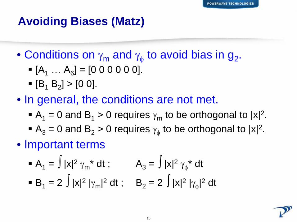
Avoiding Biases (Matz)
• Conditions on γm and γφ
to avoid bias in g2 .[A1 … A6] = [0 0 0 0 0 0].[B1 B2] > [0 0].
• In general, the conditions are not met.A1 = 0 and B1 > 0 requires γm to be orthogonal to |x|2. A3 = 0 and B2 > 0 requires γφ to be orthogonal to |x|2.
• Important termsA1 = ∫ |x|2 γm* dt ; A3 = ∫ |x|2 γφ* dt
B1 = 2 ∫ |x|2 |γm|2 dt ; B2 = 2 ∫ |x|2 |γφ|2 dt
17Confidential & Proprietary
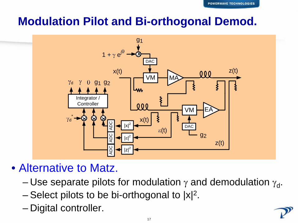
Modulation Pilot and Bi-orthogonal Demod.
• Alternative to Matz.– Use separate pilots for modulation γ
and demodulation γd .
– Select pilots to be bi-orthogonal to |x|2.– Digital controller.
z(t)
g2
MA
EA
g1
VM
VM
(t)
x(t)
x(t)
z(t)| |2
|x|2
|z|2
d*
X1 + ej
Integrator /Controller
XXX
d g1 g2
AD
CA
DC
AD
C
DAC
DAC

18Confidential & Proprietary
Differences from Matz’s Implementation
• Modulate g1 along one dimension at a given time.– Modulation direction θ.– Fewer orthogonality conditions to fulfill.
• Select a modulation and demodulation pilot pair (γ,γd ) such that
A1 = ∫ |x|2 γd * dt = 0
A2 = ∫ |x|2 |γ|2 γd * dt = 0
B1 = 2 ∫ |x|2 γ γd * dt > 0.
• Choose γd as a function of |x|2 to fulfill orthogonality condition.
19Confidential & Proprietary
Bi-Orthogonal Pilot
• Select binary modulation pilot γ
= ±ρ.Reduces orthogonality to one equation.A2 = |ρ|2 A1
• Select demodulation pilot γdγd(t) = γ(t) or 0 (masked).γγd* = |γd|2 which makes B1 > 0.
B1 = t1∫t2|x|2 |γd|2 dt > 0.
Adjust t1, t2, and masking of γd to make offset zero.A1 = t1∫
t2|x|2 γd* dt = 0.
Adjustments made in DSP after |x|2 and |z|2 have been digitized and captured.
20Confidential & Proprietary
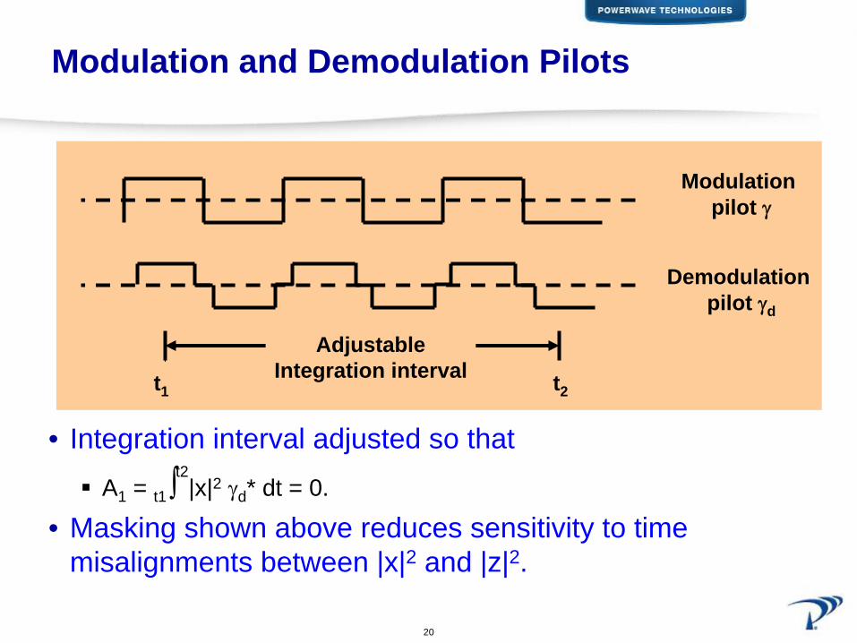
Modulation and Demodulation Pilots
• Integration interval adjusted so thatA1 = t1∫
t2|x|2 γd* dt = 0.
• Masking shown above reduces sensitivity to time misalignments between |x|2 and |z|2.
Modulation pilot γ
Demodulation pilot γd
AdjustableIntegration intervalt1 t2
21Confidential & Proprietary
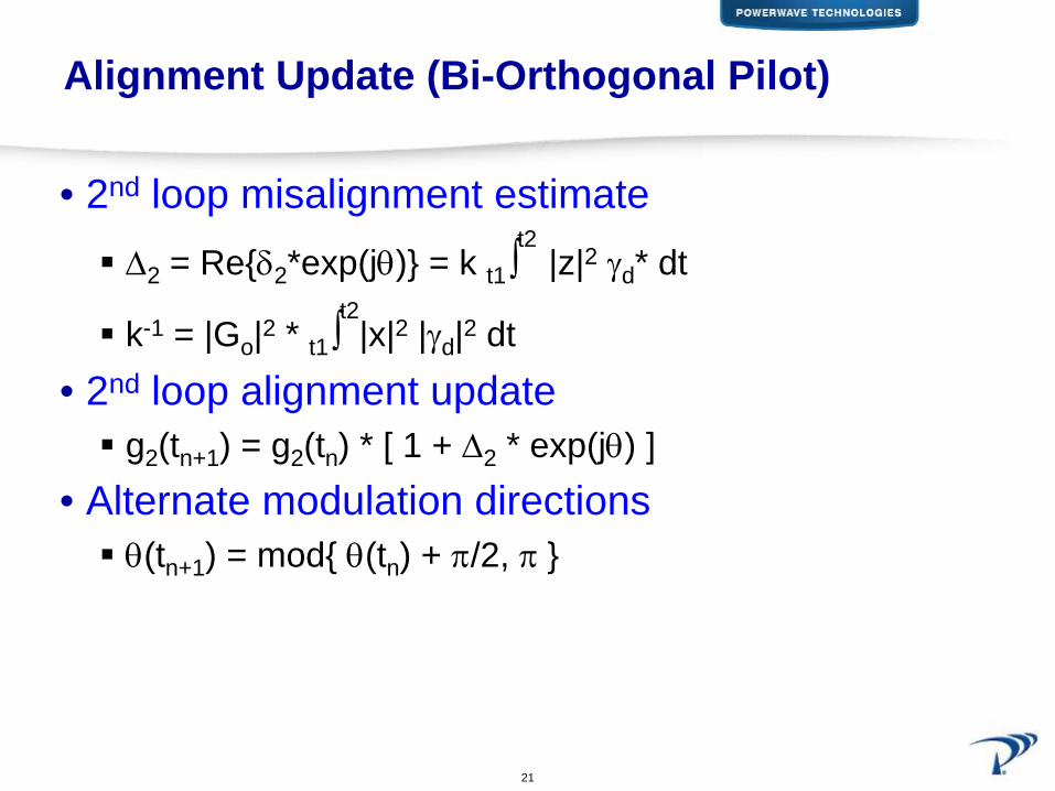
Alignment Update (Bi-Orthogonal Pilot)
• 2nd loop misalignment estimateΔ2 = Re{δ2*exp(jθ)} = k t1∫
t2|z|2 γd* dt
k-1 = |Go|2 * t1∫t2|x|2 |γd|2 dt
• 2nd loop alignment updateg2(tn+1) = g2(tn) * [ 1 + Δ2 * exp(jθ) ]
• Alternate modulation directionsθ(tn+1) = mod{ θ(tn) + π/2, π }

22Confidential & Proprietary
Challenges
• Square law responses, |x|2 and |z|2, need to be matched.• Signals need to be time aligned.• Distortion from main amplifier not considered in analysis.• Masking and calibration can reduce these problem.
z(t)
g2
MA
EA
g1
VM
VM
(t)
x(t)
x(t)
z(t)| |2
|x|2
|z|2
d*
X1 + ej
Integrator /Controller
d g1 g2
DAC
DAC
23Confidential & Proprietary
Conclusion
• Second loop control of a feedforward PA– In-band pilot obtained by modulating the alignment
control of the first loop.
• Bi-orthogonal demodulation pilot– Avoids steady state alignment offsets.
• Has potential for DL-LTE Advanced applications.

24Confidential & Proprietary
Thank You.
• Questions?


![&o Æ]À¡ y vÇ - GatesAir | TV/Radio Broadcast … Transmitter Power Supply Cabinet Output Network Cabinet RF Amplifier Cabinet Serial Modulation Encoder Module RF Power Amplifier](https://static.fdocuments.net/doc/165x107/5b4f5f9c7f8b9a396e8c3094/o-aa-y-vc-gatesair-tvradio-broadcast-transmitter-power-supply-cabinet.jpg)