![FOURIER -TRANSFORM INFRARED SPECTROMETER [FTIR]](https://static.fdocuments.net/doc/165x107/587539961a28abe7728b6867/fourier-transform-infrared-spectrometer-ftir.jpg)
A far-infrared vacuum grating spectrometer · A Far-Infrared Vacuum Grating Spectrometer 1. R....
9
JOURNAL OF RES EARCH of the National Bureau of Standards-C. Engineering and Instrumentation Vol. 67C, No.3, July-September 1963 A Far-Infrared Vacuum Grating Spectrometer 1. R. Blaine l ( March 4, 1963) . A f ar -infrar ed vac uum gr at in g s pectr omete r has been designed, built and tested at the Bur e au of Stand ar ds. This in st rume nt ha s been in oper at ion a nd und er cons tant for the past two years. Its useful range of operat ion is fr om 30 to 400 cm- I. . r he detectllll? an d dls persmg are a Go l ay pn eu matic det ecto r a nd a seri es of X 3 111 . pl a ne gratlllgs. A spectr al resolutIOn of from 0.5 to 1.0 cm- I h as been attai ned in t he r egio n betwee n 30 an d 200 em- I. The far-infr ared abso rpt ion s of seve ral halo ge nate d e thanes in the li qu id s tat e h ave been ob served and meas ur ed. Th e abso rp t io ns obser ved were: pen tac hlor oetha ne, 175.5 em- I, 164.5 cm- I, a nd 85 cm- I; symm etri c-tet r ac hloroet hane, 172.0 Clll - I a nd 87 cm- I; 1 bromo-2- chlor oet h ane, 202.0 ern-I and 123 em- I. 1. Introduction n recent years a reJl ewed a nd e nl arged int erest ha s be en aroused in th e dire ct J11 easuremen t or spect ra below 200 cm -I. It is in this low frequency reg ion that .o ne observ es absorption band s arisin g from the bendll1 g and twi stin g mod es or complex mol ec ulcs. This work is primarily co ncern cd with lhc C0 11 - s tru ction of a.n in s trument or medium r cs oluti on th at would be capabJ e of observing n,nd measuring the se low ly in g frequencies. J 2. Equipment In or eler to design a vaeuumV in stnu11 cn t that would possess the convenience n, nd a cl apln,bility necessary for. t he. num erous phases of infrar ed research, four baslc alms were used as guid es : (1) the ma int aini11 g of. a m aXllllum level of s our ce ell er gy, (2 ) t he use or moun ts th at co uld eas il y be ada pLed Lo many sltuatlOn s, (3 ) the accessibili ty or optical component s for con venient ad just m en t in ter change, a nd (4) the allowan ce for sub se qu ent impro vemen ts on the in strum ent , both in size and quality. 2.1. Instrument Housing The instr ument housing as shown in figures 1 and 2 is divided into four sep arate chambers each of is accessible tlu' ?ugh one or mor e cov'er plates. I hese chamber s are mter connected by three fo cal plal!e windows. window. and covel' plate is O-rmg sealed and has ltS mountm g holes indexed for rapid in terchange an d adaptation. The main section, composed of c hamb ers C2 and C3, was fabricated from 9{6 -i n. aluminum plate. was rolled into a cylinder 72 in. long X 22 m. 111 chameter. All of the joints we re heli-arc welded. Chamb ers C1 ftnd C4 were fabricated from the same material an d can be detached from tbe main housin g. 1 This work was done in partial fulfillment of the r eq uir ement s for Ill e degree of Master of SCience for the Gradu a te Chool of tI,e UniverS ity of M aryl and. Clmmber C1 houses the source and source optics ( fi g. 2) . Lt Inft y be flu shed with ft dr y inert gftS or eva.c ua ted as the reseftrch all ows. Liquid or gas absorption cells . up to 10 cm in len gth m ay be pbced in the p ftt h between M2 n,nd VV1. Oh am bel' 02 is esse ll tially a var iable pftth gftS cell. Th e pn,th leng th m ay be varied from 2 to 6 m.. Th e refl ector, MR , is ft six- position t urr et th at is controlled from cover A3 . On this t urr et plane refl ectors are mounted and selected as needed. The monochromator chambel' C3 is of su ffi cient size to hou se n, sp ec trolll eter Imvi ng a fo cal lel lO'th of 60 cm. At pr esen t ft mod ifi ed 'monochromn1or section of a Perkin-Elmer Model ] 2 single-beam is being use d. Th e grftting tur n Lable IS by an extern ally located synchronous motor. An O-rlllg scaled shaf t transmits the power through th e vacuum wftll ftt cover AS. Th e monochromator slits are driv en by an electric motor lo cate d within the VftCll Um ch ft mb er. Sli t motor and d etector arc brought outside through the Ko var seals m cover A 7. Cover A6 provides fo r access to the gr ating and co n tain s ft gl ftss window for ob servation p\lrposes. 02 and 03 there is a sep arating wmdow W2, WhlOh can be removed or inst alled as the research demands. This allows one to mftke use of the added p ath l ength of the monochrom ator whenever noncorrosive gases arc being studied. Chamb er 04 is used specifically to house the Golay pn eumatic det ector and may be flu sh ed with dry nitrog en or evacuated. Th e covel' of this chamber is hin ged and is fi tted with Kovar seals for signal and power connection s. In t hi s ch am b e l' liquid and gas absorption cells up to 15 cm in length may be in trodu ced into the opticftl pftth ftt window W3. . Th.e vB:cu um system is of a forcpump, oil dlffu slOn pump, ftncl strat eglcally lo cated cold traps ( fi g. 1) . Cham bel' S C2 and C3 are evacua,ted t hrou gh 4-in. co pp er tubing beginning at cover s A2 an d A5 and joining at th e cold trap 'h . Preceding the cold trap 'II , th ere is ft 4-in . 30 0 lit er/sec oil diffusion pump PI. Preceding PI is a pacld ess 207
-
Upload
phungthuan -
Category
Documents
-
view
216 -
download
0
Transcript of A far-infrared vacuum grating spectrometer · A Far-Infrared Vacuum Grating Spectrometer 1. R....
JOURNAL OF RESEARCH of the National Bureau of Standards-C. Engineering and Instrumentation Vol. 67C, No.3, July-September 1963
A Far-Infrared Vacuum Grating Spectrometer 1. R. Blaine l
(March 4, 1963)
. A far-infrared vacuum gratin g spectrometer has bee n des igned , bui lt a nd tested at the ~at lonal Bureau of Standar ds. This instrument has been in operation a nd under constant ~r;tprovement for the past two years. Its useful r a nge of operation is fr om 30 to 400 cm- I . . r he detectllll? and dls persmg ele)nen~s are a Golay pneu ma t ic detector and a series of 2~~ X 3 111 . pla ne gratlllgs. A spectral resolu tIOn of from 0.5 to 1.0 cm- I has been a t tained in t he r egio n between 30 and 200 em- I.
The far-infrar ed absorpt ions of severa l haloge nated etha nes in t he li qu id state h ave been obser ved and meas ured . The a bsorpt ions obser ved were: p entachloroethane, 175.5 em- I, 164.5 cm- I, and 85 cm- I; sy mmetri c-tetrac hloroeth a ne, 172.0 Clll- I and 87 cm- I; 1 bromo-2-chloroet hane, 202.0 ern- I and 123 em- I.
1. Introduction
n recent years a reJl ewed a nd enlarged interest has been aroused in the direct J11 easuremen t or spectra below 200 cm - I . It is in this low frequ ency region that .one observes absorp tion bands arisin g from the bendll1g and twisting modes or complex moleculcs.
This work is primarily concern cd with lhc C0 11 -struction of a.n in strument or m edium rcsolution tha t would be capabJe of observin g n,nd measurin g these low lyin g frequencies. J
2. Equipment
In oreler to design a vaeuumVinstnu11 cn t that would possess the convenience n,nd aclapln,bility necessary for. the. num erous phases of infrared research , four baslc alms wer e used as guides : (1) the maintaini11 g of. a m aXllllum level of source ell ergy, (2) t he use or '~71Odo.w moun ts that could easily be adapLed Lo many sltuatlOns, (3) the accessibili ty or optical compon ents for con venient ad justmen t ~l.llcl in ter change, and (4) the allowance for subsequent improvemen ts on the instrum ent, both in size and quality.
2.1. Instrument Housing
The instrumen t housing as shown in figures 1 and 2 is divided into four separate chambers each of ;~hich is accessible t lu'?ugh one or more cov'er plates. I hese chambers are mterconn ected by t hree focal plal!e windows. Eac~ window. and covel' plate is O-rmg sealed and has ltS mountmg holes indexed for rapid in terchange an d adaptation.
The main section , composed of chambers C2 and C3, was fabricated from 9{6-in. aluminum plate. :rhe'plat~ was rolled into a cylinder 72 in. long X 22 m. 111 chameter. All of the join ts were h eli-arc welded. Chambers C1 ftnd C4 were fabricated from the same material and can be detached from tb e main housing.
1 This work was done in partial fulfillment of the r eq uirements for Ille degree of Mas ter of SCience for th e Graduate Ch ool of tI,e UniverSity of M aryland.
Clm mber C1 houses the source and source opti cs (fi g. 2) . Lt Infty be flu shed with ft dry inert gftS or eva.cua ted as the reseftrch allows. Liquid or gas absorp tion cells . up to 10 cm in length may be pbced in the pftth between M2 n,nd VV1.
Oh am bel' 02 is essell tially a variable pftth gftS ~bsorp tion cell . The pn,th length may be varied from 2 to 6 m.. The reflector, MR, is ft six-position turret that is controlled from cover A3 . On this turret plane reflectors are mounted an d selected as needed.
The monochrom ator cham bel' C3 is of su ffi cient size to hou se n, spectrolll eter Imvi ng a focal lel lO'th of 60 cm. At presen t ft modifi ed 'monochromn1or section of a Perkin-Elmer Model ] 2 single-beam ~pcc~rom eter is being used. The gr ftting turn Lable IS clnve~l by an externally located synchronous motor. An O-rlllg scaled shaf t tran smits the power through the vacuum wftll ftt cover AS. The monochromator slits are driven by an electric motor located within th e VftCllUm ch ft mber. Sli t motor and detector ~ eftds arc brough t outside through the Kovar seals m cover A 7. Cover A6 provides for access to the gr ating and con tains ft glftss window for observation p\lrposes. Betw~en 02 and 03 there is a separating wmdow W2, WhlOh can be removed or installed as the research demands. This allows one to mftke use of the added path length of th e monochromator whenever noncorrosive gases arc being studi ed.
Chamber 04 is used specifically to hou se the Golay pneumatic detector and may be flu shed with dry nitrogen or evacuated . Th e covel' of this chamber is hinged and is fi tted with Kovar seals for signal and power connections. In this ch am bel' liquid and gas absorption cells up to 15 cm in length may be in troduced into the opticftl pftth ftt window W3.
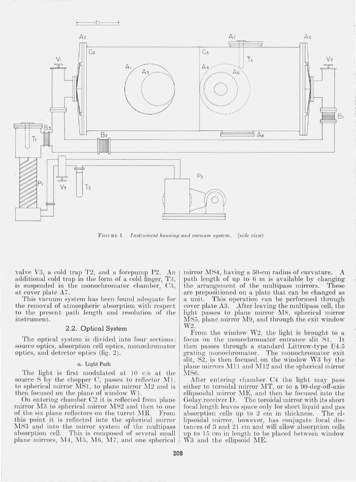
. Th.e vB:cuum system is compo~ed of a forcpump, oil dlffu slOn pump, ftncl strateglcally located cold traps (fig. 1) . Cham bel'S C2 and C3 are evacua,ted through 4-in. copper tubin g beginning at covers A2 and A5 and joining at the cold trap 'h. Preceding the cold trap 'II , there is ft 4-in . 300 liter/sec oil diffusion pump PI. Preceding PI is a pacld ess
207
A5
A~ __ ----- -- ____ \
-,
FJG URE 1. Instrument h01lsing and vacuum system. (side view)
valve V3, a cold trap T2, and a forepump P2. An additional cold trap in the form of a cold finger, T3, is suspended in the monochromator chamber, C3, at cover plate A7.
This vacuum system has been found adequate for the removal of atmospheric absorption with respect to the present path length and resolution of the instrument.
2.2. Optical System
The optical system is divided into four sections: source optics, absorption cell optics, monochromator optics, and detector optics (fig. 2).
a. Light Path
The light is first modulated at 10 cis at the source S by the chopper C, passes to reflector M:l , to spherical mirror MSl , to plane mirror ::'12 and is then focused on the plane of window vn .
On entering chamber C2 it is reflected from plane mirror M3 to spherical mirror MS2 and then to one of the six plane reflectors on the turret MR. From this point it is reflected into the spherical mirror MS3 and into the mirror system of the multipass absorption cell. This is composed of several small plane mirrors, 1\14, M5, M6 , M7, and one spherical
208
mirror MS4, having a 50-cm radius of curvature. A path length of up to 6 m is available by changing the arrangement of the multipass mirrors. These are prepositioned on a plate that can be changed as a unit. This operation can be performed through cover plate A3. After leaving the multipass cell, the light passes to plane mirror M8, spherical mirror MS5, plane mirror M9, and throngh the exit window W2.
From the window W2, the light is brought to a focus on the monochromator entrance slit S1. It then passes through a standard Littrow-type f /4.5 grating monochromator. The monochromator exit slit, S2, is then fo cused on the window W3 by the plane mirrors MIl anel M12 and the spherical mirror MS6.
After entering chamber C4 the light may pass either to toroidal mirror MT, or to a 90-deg-off-axis ellipsoidal mirror ::,;fE, ftnd then be focused into the Golay receiver D. The toroidal mirror with its short focal length leaves space only for short liquid and gas absorption cells up to 2 cm in thickness. The ellipsoidal mirror, however, has conjugate focal distances of 3 and 21 cm and will allow absorption cells up to 15 cnl in length to be placed between window W3 and the ellipsoid ME.

1ft ·1
M r----------,
IE~- 1 0 t:J I~ ~ __________ J
MS6
,--'--'-7'-------.1.-----.- --, W4 ,--'----, __________ ___
s
c FlGum: 2.
1. Monochromator and Modifications
(1) Grating drive. The P .E . 12 is a prism instrument and its Li ttrow mirror is ro tated by a sine bar which allows only 10 deg of angular rotation. In order to elimina te this inconvenience and ob tain 360 deg of rotational freedom the sine bar was remo ved and a precision worm gear subs t ituted. Connection was then made to the power shaft at AS. The prism table was removed and a suitable grating mount was substitu ted for the standard Li ttrow mirror mount.
The grating turntable driving system consists of a synchronous motor, standard three-speed transmission , sever al precision worm gears, a rotation counter , fLn O-ring sealed drive shaft, and an independen t rapid traverse drive motor. The synchronous motor havinlS a variable speed-reducer gives a r ange of scanmng speeds from 1.2 to 0.16 deg of ar c per minu te of tim e. This provides scanning speeds compatible with the tim e constan ts of the detector system .
The rapid traverse drive is specifLcally designed for rapid posi tioning of th e grating and gives a scanning !'fLte of 31.4 cleg/min of tim e.
Opt ical system .
(2) Slits. The bilater fLl sli ts are geared to an electric motor which is located within the vacuum chamb er C3, and controlled from an outside switch panel. A Veeder-Roo t ro tation counter located in the gear train enables one to determine th e slit wid th to within a few microns. This counter is readily observed through the window in cover A6.
(3) Optical modijication. In order tbat the Golay detector could be placed in chamber C4, under atmospheric pressure, t he standard optical system behind the monochromator exit slit, 82, bad to be rearranged so as to focus the image of 82 on the window W3. This was accomplished by installing the plane mirrors M1l and M1 2 and the spherical mirror M86.
(4) E lectrical system. Con trols for the sli t drive, grating drives and vacuum gages are mounted on a con tro l panel which is located on the instrum ent suppor t frame. The electric motors that power these componen ts are single phase ratio-motors 2 having a rating or approxim ately 1/100 hp. P ower or signal
2 Electric motors equipped with a built·in speed reducer.
209
leads that pass in and out of the individual chambers are fed through the cover plates with Kovar seals.
The signal detection system 3 consists of a Golay pneumatic detector and associated equipment so that the signal is amplified and ultimately recorded on a strip chart.
3. Spectroscopy in the Far Infrared
3.1. Sources
The choice of a good SOUTce for far infrared absorption studies is somewhat limited. The region from 400 to 100 cm- I is efficiently covered by the global'. Below 100 cm- Ia high pressUTe mercUTy arc is used.
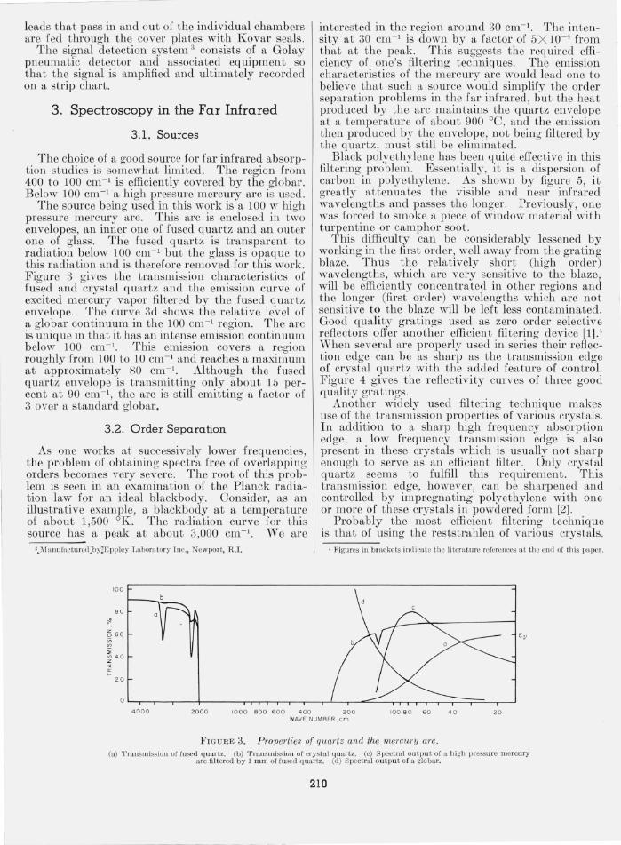
The SOUTce being used in this work is a 100 w high preSSUTe mercUTY arc. This arc is enclosed in two envelopes, an inner one of fused quartz and an outer one of glass. The fused quartz is transparent to radiation below 100 cm- l but the glass is opaque to this radiation and is therefore removed for this work. FigUTe 3 gives the transmission characteristics of fused and crystal quartz and the emission CUTve of excited mercUTY vapor filtered by the fused quartz envelope. The CUTve 3d shows the relative level of a global' continuum in the 100 cm- l region. The arc is unique in that it has an intense emission continuum below 100 cm- l . This emission covers a region roughly from 100 to 10 cm- l and reaches a maximum at approximately 80 cm- l . Although the fused quartz envelope is transmitting only abou t 15 percent at 90 cm- l , the arc is still emitting a factor of 3 over a standard global'.
3.2. Order Separation
As one works at successively lower frequencies , the problem of obtaining spectra free of overlapping orders becomes very severe. The root of this problem is seen in an examination of the Planck radiation law for an ideal blackbody. Consider, as an illustrative example, a blackbody at a temperature of about 1,500 OK. The radiation CUTve for this source has a peak at about 3,000 cm- I. vVe are
3 ... Manuractured~by2Eppley I"aboratory Inc. , Newport, R.I.
100
8 0
56 0
~ '" V> 4 0 z " '" ...
20
interested in the region around 30 cm- I. The intensity at 30 cm-I is down by a factor of 5X 10- 4 from that at the peale This suggests the required efficiency of one's filtering techniques. The emission characteristics of the mercury arc would lead one to believe that such a SOUTce would simplify the order separation problems in the far infrared, but the heat produced by the arc maintains the quartz envelope at a temperatUTe or about 900 DC, and the emission then produced by the envelope, not being filtered by the quartz, must s till be eliminated.
Black polyethylene has been quite effective in this filtering problem. Essentially, it is a dispersion of carbon in polyethylene. As shown by figure 5, it greatly attenuates the visible and near infrared wavelengths and passes the longer. Previously, one was forced to smoke a piece of window material with tUTpentine or camphor soot.
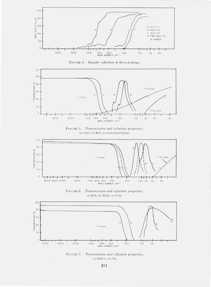
This difficulty can be considerably lessened by working in the first order, well away from the grating blaze. Thus the relatively short (high order) wavelengths, which are very sensitive to the blaze, will be efficiently concentrated in other regions and the longer (first order) wavelengths which are not sensitive to the blaze will be left less contaminated. Good quality gratings used as zero order selective reflectors offer ano ther efficient filtering device [1].4 When several are properly used in series their reflection edge can be as sharp as the transmission edge of crystal quartz with the added feature of control. FigUTe 4 gives the reflectivity CUTves of three good quality gratings.
Another widely used filtering technique makes use of the transmission properties of various crystals. In addition to a sharp high frequency absorption edge, a low frequency transmission edge is also present in these crystals which is usually not sharp enough to serve as an efficient filter. Only crystal quartz seems to fulfill this requirement. This transmission edge, however, can be sharpened and controlled by impregnating polyethylene with one or more of these crystals in powdered form [2] .
Probably the most efficient filtering technique is that of using the reststrahlen of various crystals.
4 Figures in bracke ts indicatc the litera ture references a t the end of th is pa per.
4 000 2000 1000 800 6 00 4 00 20 0 100 8 0 60 4 0 20 WAVE NUMBER ,em
FIGURE 3. Properties of quartz and the mercury arc. (a) T ransmi ssion of fused quartz. (b) Transmission of crysta l quartz. (c) Spectral output of a high pressure mercury
a rc filtered by 1 mill of fused q uartz. (d) Spectral output of a global'.
210
- - - - --------
100
., 80 >--I-
;; 6 0 l-V W ..J 4 0 "-w a:
20
0
4000 2000 1000 600 4 00 200 100 WAVE NUMBER ,cm- I
FIG U RE 4. Regldar reflection of three gmtings .
1875 I/in
10001/ 1n .
6001/in .
TWO 600 I/in .
I N SE RIES
60 4 0
120 r---------------------------------------------------------------------------------,
lao I-______________ ""_~
~ 8 0 z o Vi ~ 60
" '" z g 4 0
20
100
80
Q 60
'" '" " '" 4 0 z " a: I-
20
o
4000
8000 6000 4 000
t= Smm
2000 1000 600 400 200 lao WAVE NUMBER I cm- t
F 1GU RE 5. Transmission and 1'eflecti on properties. (a) NaC l, (b) K Cl, (c) b lack pol yeth y lene.
t =5 mm
60 40
2000 1000 8 00 600 400 200 100 80 60 WAVE NU M BER, em-I
FIG U RE 6. Transmission and Tejlection properties . (a) KBr, (b) Rb13r, (e) Cs 13 r.
20
t =O.2 mm
40
lOO r----------------------------------------------------------------------------------,
., 80 .-_______________________________________ ___
g 60
~ ~ '" 40 z " ::
20
8000 4000
t=smm
2000 1000 600 400 200 10 0 WAVE NUMBER. cm-I
FI G UR1, 7. Transmission and 1'eflection properties. (a) KRS-5, ( I)) CsT.
211
a,
60
Many of these crystals h ave a peak reflectivity of 90 percent and cover a reasonably narrow spectral interval.
In all cases the separation of spectral orders requires st,rategic use of the reflective, scattering, and transmissive properties of m any materials. Figures 5, 6, and 7 give a sequence of transmission and reflection curves for a number of materials. They are arranged in order of their usefulness with respect to decreasing frequency.
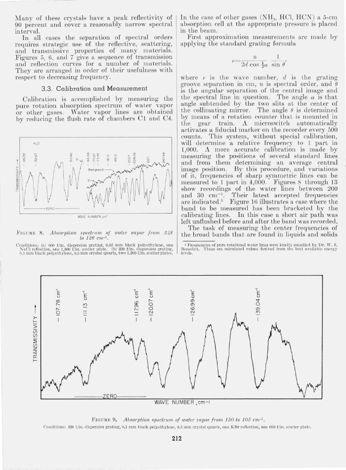
3 .3 . Calib ration and Mea surement
Calibration is accomplished by measuring the pure rotation absorption spectrum of water vapor or other gases. W ater vapor lines are obtained by reducing the flush rate of chambers C1 and C4.
H,O
:g '- ~ N " ~ " ! '" <ri g ~ ~ 'f> ro
--- lERO----
WAVE NUMBER,cm·'
FIG U RE 8. AbsoTption spectTum of water va pOl' fTom 248 to 126 em-I.
Conditions: (a) 600 l /ill. dispersion grating, 0.05 mm black polyethylene, one ~aCl refl ection, olle 1,800 l /in. sca tter plate. (b) 320 l /in. dispersion grating, 0. 1 mm black polyethylene, 0.5 mm crystal quartz, two 1,200 l/in. sca tter plates .
ZERO
In the case of other gases (NH 3, H CI, H CN) a 5-cm absorption cell at the appropriate pressure is placed in the b eam.
First approximation measmements are made by applying the standard grating formula
n 1 v
2d coS!a sin 0'
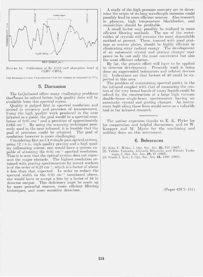
where v is the wave number, cl is th e grating groove separation in cm, n is spectral order, and 0 is the angular separation of the central image and the spectral line in question. The angle a is that angle sub tended by the two slits at the center of the collimating mirror. The angle e is determined by means of a rotation counter tha t is mounted in the gear train. A microswitch automatically activates a fiducial marker on the recorder every 500 counts. This system, without special calibration, will determine a relative frequency to 1 part in 1,000. A 1I1Ore accurate calibra tion is made by measuring the positions of several s tandard lines and from them determining an average central image position. By this procedure, and variations of it, frequencies of sh arp symmetric lines can be measured to 1 part in 4,000. Figures 8 through 13 show recordings of the water lines between 200 and 30 em- I. Their latest accepted frequencies are indicated! Figure 16 illustrates a case where the band to be measured has been bracketed by the calibrating lines. In this case a shor t air path was left unflushed b efore and after the band was recorded.
The task of measuring the center frequencies of the broad bands that are found in liquids and solids
• Frequcncies of pure rotational water lines were kindly supplied by Dr. W . S. Benedict. These are calcula ted values derived from the bes t available energy lm'els.
WAVE NUMBER, cm- l
FIGU RE 9. Absorption spectrum of water vapor from 150 to 105 em-I. Conditions: 320 l/in, dispersion gra t ing, 0.1 mm black polyethylcne, 0.5 mm crystal quartz , one KBr reflection, one 600 l/in , scatter pla te.
212

>f-;; (f) (f)
~' (f) z <J: cr f-
o N N r---
- - - ----- -_ .. _- --
ZERO WAV E NUMBER,cm-'
FIGURE 10. Absorption spectrum of water vapor /1'om 115 to 70 em-I. Conditions: 320 liin. dispersion grating, 0.1 mm black polyethylene, l.0 mm crystal qnar tz, one CsEr reflection, two 600 I/in. scaLter p lates.
>f-
2 (j) (j)
~ (j) Z <l 0:: f-
----ZERO----
WAVE NUMBER ,em-I
FI GUlm 11 . Absorption spectnt?n oj water vap01' from 92 to 59 em-I.
Conditions: 180 liin. dispersion gratin g, 0.2 mm black pol yethylene, l.0 m111 crystal quartz, one KRS-5 renecLion, two 320 l iin. scatter plates.
presents a difficulty which greatly reduces the precision and accuracy of measm ement. Those bands having widths 6 between 5 and 20 cm- I are in general no problem except in that their wid th makes it impossible to determine their centers precisely. A special problem is presented by those bands having widths greater than 20 cm- I . This is due to the fact that in r egions where the reststrahlen of a crystaJ are a necessary par t of the filtering technique, the energy con tom is usually no wider than th e absorption band to b e measm ed . In many cases the band contolLl' is never directly observed, but must be ob tained by sub tracting ou t the reststrahlen b ackground. The band center is t hen measm ed from a plo tted con tour. This greatly reduces the attainable precision and acc uracy.
, Line widths = rull li ne width a t half intensity.
)0-f-0; ifi (f)
~ (f) Z <! 0: f-
---ZERO---
WAVE NUMBER ,em-I
F I GURE 12. Absorption spectrwn oj water vapor from 64-to 50 em-I.
Conditions: 180 l iin. dispersion gra ting, 0.2 111111 black polye thylene, l.0 mm crystal q uartz, 0.5 mill LiP, one KRS-5 reflection, two 320 li in. sca Ller plates.
4. Observations and Measurements
In addi tion to the spectra of water vapor, the low lying absorptions of some haloethanes were observed . The compounds (E astman Kodak) examined were of high purity. The high purity was affirmed by an examination of their infrared spectrum from 4 ,000 to 150 cm- I .
The compounds observed were: pentachloroethane, I -bromo-2-chloroethane, and symmetric-tetrachloroethane. The b ands observed are lis ted in table 1. Those bands that were directly observable are shown in figures 14, 15, and 16 and are given t o ± 0.5 cm- 1. The 10\Ver frequency b ands, however , were extremely broad (25 to 50 cm- 1) Hnd l11'e correspondingly less precise.
213
L
>-f-;; ifi (f)
~ (f)
Z <l 0:: f-
>f-
2 (f) (f)
~ (f) Z <l 0:: f-
N
'"
------- ZERO
WAVE NUMBER,em'
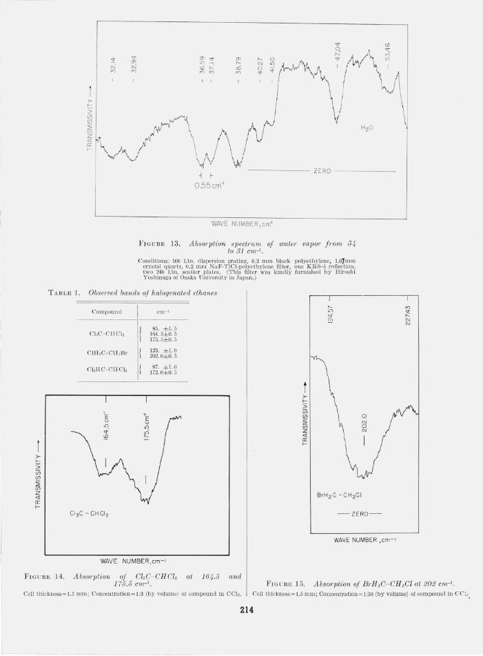
FIGURE 13. Absorption speetl'um oJ water vapor Jrom 54 to 31 em-I.
Conditions: 100 1/in. dispersion grating, 0.2 mm black polyethylene, 1.0:rmm cr ystal quartz, 0.2 mm NaF-TICI-polyethylene filter, one KRS-5 reflection , two 240 1/ill. sca tter plates. (This filter was kindly furnished by Hiroshi Yoshinaga of Osaka University in Japan.)
TABLE 1. Observed bands oJ halogenated ethanes
Compound cm- 1
85. ±1.5 CbC- CnCJ, 164. 5±0. 5
175. 5±0. 5
ClIT,C-Cn,Br 123. ±l.O 202.0±0.5
ChHC-CHCJ, 87. ±1.0 172. O±O. 5
t >-f-;; ifi <£? :2' (f) Z <! 0:: f-
CI 3C-CHCI 2 -ZERO-
WAVE NUMBER ,em-I
WAVE NUMBER,cm- 1
'" ;2: N N
FIGURE 14. Absorption of CI3C-CHCI2 at 164.5 and 175.5 em-I. FI GClm ] 5, Absorption oJ BI'H 2C-CH 2CI at 202 em-I,
Cell thickness~ 1.5 mm ; Concentratiol1~1:3 (by volume) of co mpound in CCk Cell thickncss~ 1. 5 mm; Coneentration~1:30 (by volume) of componnd in Cel, .
214
>lS; iii (/) .:!' (/) z <{
'" I-
flushed region
I
WAVE NUMBER,crn-1
FIG U RE 16. Calibration of Ihe 172.0 em-! absorption band of CI2H C- CH CI2•
Cell thickness~ 1.5 mm; Concc ll tration ~ l:l0 (b y volume) of compound ill CCI, .
5. Discussion
The far~infrared offers many ch.allengin g problems thatfmust" be solved bef'ore high quali ty data will be available from this spectral region.
Quality is judged fll'St in spectra1 r esolution fL nd second in n.ccuracy fL nd precision of meaSUl'emen t. Using the high qUfLlity work produced in the ncar infrared as fL guide, t he gOfLl would be a spectral resolution of 0.03 cm- 1 and a precisioll of a pproximately 0.005 em- I. By using t he scan nin g techniques presently used in the ncar in frn.red, it is r easible t hat the goal of precision could be a.ttain ed. The goal of resolution however is more challengin g.
Considering first fL ll 1' /4.0 sin gle pass opLical system , usin g 12 X 8 in . high quality graLing and a high quali ty collim ating mirror , one would hcwe a system . capable of fLttainin g Lile 0.03 CI11- 1 spectral resolution. Thus it is seen Lhat t he opLicnl system docs no t r epresen t the major obsLaele. The highest r esoluLion aLtained with grating spectrometers by recent workers is of the order of 0.25 em- I, which is a ffl.ctor of about 8 less than Lhat expected. In order to r educe t ltO spectral width to t he 0.03 em- I men.tioned ~bov.e, one would h ave to accept n. loss by a lactor 01 64 In detector output. This deficiency must be made up by more powerful sources , more efficient filtering techniques, and more sensitive detectors .
A study of the high pressure mercury arc to determine the origin of its lon g wfl.velength emission could possibly lead to more efficien t sources . Also resefLrch in plasm as, high tempemture blackbodies, and cmissi vi ties should be profitable.
A small fa.cLOl' ma.y possibly be reali zed in more effi cicn t filteri ng meLllOds. Th e use of t he r eststm hlen of crysb{ls still remains Lhc 11l 0sL c1e])end fLble met hod fLt prescnt. Thesc, Le<llllcd with good gratin gs as scat tcr platcs, SllOUld be highly cificienL in eliminfLLin g sLray mdia nL Cll crgy. Thc devclopmcnt or an a utomat ic c/'ysLal ~Lllcl gmLill g c1mllge/' m ay prove to be no t only LitO m ost cO ll velllcllL but n,lso thc most efficiell t solution.
By far , t he greaLer effort will ha vc Lo be H ppliecl to deLect.or developmenL. Prescll tly work is bein g don e on supercooled bolomcLers cLnd l'Chl Led deviccs [3]. Indications arc Lltctt fn.cLors 01' 40 co uld bc expec ted in t Itis <1.1'Cc1.
The problem or ll1 a ill L~linill g spcclml purity ill Lhe far i llfmred cou pled wiLit LltaL or measurin g the cenLers or tite very broad ballds or lll any li qu id s ('ould be solved by Lhc consLruct ion 01' ~L large Itig lt vac uum double-beall1- singlc-becLIll s pccLromeLer hn.vill g a n a uLomatic cl'ysLal ~mcl gmLillg elUl ll gCl'. AllinsLl'ulll enL built along thesc lill cs would scr vc as a vcl lu able tool in far infrarcclrescal'ch.
The autilOr exprcsses Lltan ks Lo E. E:. Plyler for his coopera.t ion and helpful disc ussions, and to Tfl. Koep pel' and 1\1£. .Myers 1'01' the IWLc hinin g fLnd wcldin g clon c 011 this in strument.
6. References
[1] John U. Whi te , J. Opt. Soc. Am. 37 , 713 (1947) . [2] Yahiko Yamada, Akiyoshi Mit~ui s hl, and Hirosh i Yoshi
naga, J . Opt. Soc. Am . 52, 17 (1962) . [3] Frank J. Low, J. Opt. Soc. Am. 51, 1300 (1961).
(Paper 67C3- 131)
215