A FAILURE SURVEY DF FREESTANDING WALLS - … · A FAILURE SURVEY DF FREESTANDING WALLS ... the...
10
936 A FAILURE SURVEY DF FREESTANDING WALLS JOHN MORTON The Brick Development Association Woodside House, Winkfield, Windsor, Berkshire SL4 2DX R 5 NARAYANAN and N J HUBAND 5 B Tietz & Partners Consulting Engineers 10/ 14 Macklin Street, London WC1B 5NF ABSTRACT When strong winds occur in a particular locality they often result in failures of some freestanding walls and other structural and non- structural damage. This paper addresses the question of why freestanding walls blow over - sometimes even when the wind load applied is less than the design wind load. It also addresses the technical question of whether it is correct to use a "flexure plus gravity" design approach or whether freestanding walls should be designed solely on a gravity basis. The majority of walls are small - of the order of 2 m or less in height. Ta ll walls are usually stable by gravity even if there is no flexural bond. This is not the case with small walls: any loss of bond impairs the stability. Consequently for small walls the method of design greatly affects the cost; gravity walls become much more expensive than similar height walls which are designed on a gravity and flexure basis. To gain a greater understanding of why freestanding walls fail case studies of failures were collected and analysed. Twenty recent wall failures were found and analysed structurally and physically to determine the cause of failure. When alI the facts were assessed it was found that alI the wall failures could have been predicted. The paper concludes that there is no evidence to suggest that it is unsound to design walls on a gravity plus flexure basis. The evidence , however, does indicate a need for a greater educational effort to ensure that walls are designed and not merely "put up": similarly it is important to ensure that the leveI of workmanship is appropriate and fulfils the . design requirements.
-
Upload
trinhkhanh -
Category
Documents
-
view
223 -
download
0
Transcript of A FAILURE SURVEY DF FREESTANDING WALLS - … · A FAILURE SURVEY DF FREESTANDING WALLS ... the...
936
A FAILURE SURVEY DF FREESTANDING WALLS
JOHN MORTON The Brick Development Association
Woodside House, Winkfield, Windsor, Berkshire SL4 2DX R 5 NARAYANAN
and N J HUBAND
5 B Tietz & Partners Consulting Engineers
10/ 14 Macklin Street, London WC1B 5NF
ABSTRACT
When strong winds occur in a particular locality they often result in failures of some freestanding walls and other structural and nonstructural damage. This paper addresses the question of why freestanding walls blow over - sometimes even when the wind load applied is less than the design wind load. It also addresses the technical question of whether it is correct to use a "flexure plus gravity" design approach or whether freestanding walls should be designed solely on a gravity basis. The majority of walls are small - of the order of 2 m or less in height. Tall walls are usually stable by gravity even if there is no flexural bond. This is not the case with small walls: any loss of bond impairs the stability. Consequently for small walls the method of design greatly affects the cost; gravity walls become much more expensive than similar height walls which are designed on a gravity and flexure basis.
To gain a greater understanding of why freestanding walls fail case studies of failures were collected and analysed. Twenty recent wall failures were found and analysed structurally and physically to determine the cause of failure. When alI the facts were assessed it was found that alI the wall failures could have been predicted. The paper concludes that there is no evidence to suggest that it is unsound to design walls on a gravity plus flexure basis. The evidence , however, does indicate a need for a greater educational effort to ensure that walls are designed and not merely "put up": similarly it is important to ensure that the leveI of workmanship is appropriate and fulfils the. design requirements.
937 • INTRDDUCTION
That freestanding walls collapse under strong within the design and construction industry. strong gust occurs, one or more free standing - together, it has to be said , with the other suffer local storm damage .
seasonal winds is well known Whenever a particularly walls in the locality fail forms of construction which
The question is WHY these walls collapse has exercised much attention recently. This quest-ion may have been raised, perhaps, because Df the recent debate on whether free standing boundary walls should be subject to Building Regulation approval.
BASIS DF DESIGN
The question Df which method should be used to design freestanding walls has been the subject Df discussion on many occasions both within the brick industry and within the relevant Code Technical Drafting Committees.
This is somewhat more than a matter of academic debate since according to government statistics there have been 9 fatalities* resulting from wall failures Df free stand i ng walls in the past 20 years.
In the BDA Design Guide on Free St anding Walls ( 1 ) various design methods are reviewed and a design approach based on a combination Df flexural strength and dead load is advocated.
Equally it is clear that if this design approach is adopted, and the flexural strength then "fails" or "disappears" the wall ' s ability to res ist load is impaired. Furthermore t his effect becomes more pronounced in smaller walls. There is s imply insufficient height in such walls to generate enough dead load to provide the stability moment: bending tension across the mortar joint has to be relied on. By the large, this means that for walls Df ~2 m or less in height the 'loss' Df flexural bond will result in the wall being unstable when analysed theoretically.
Taller walls can more readi l y be justified by the 'gravity method' because, although the design moment increased, the moment Df resistance increased at a greater rate.
Needless to say small walls predominate in Britain as simple boundary walls. It is therefore this major type Df wall which could be considered to be at risk.
Which method should be advocated - purely gravity design or a combination Df flexural resistance and dead load?
To answer this question it was necessary to decide whether, by and large, walls failed because
* Up to date Df December 31st 1986

938
1) the flexural bond is 'lost' with time DR 2) they were originally incorrectly constructed either with an
inadequate section or faults in construction.
lo seek an answer to this question it was decided to collate as much information on as many wall failures as possible. It was recognised that when investigating failures not only is the 'portcullis' lowered but the 'draw bridge' is generally raised as well. Nothwithstanding this by a careful approach a seIection of wall failures was collated and analysed to see whether failure could be predicted or noto It is not suggested, therefore, that this survey is 'full' or 'complete'. Nonetheless the survey is a genuine attempt to obtain and analyse wall failures to gain an understanding of why failure occurred.
Obtaining the evidence 5tandard pro forma sheets were sent to a number of organisation to collect the data. Primarily these were aimed at finding out the location, the thickness and height of the walls. Information on any DPC at the base of the walls was also sought .
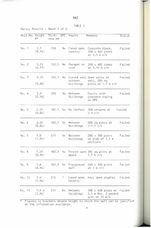
Data on 20 cases were received. Df these 19 related to actual failures; the other one was a potentially dangerous wall. Data was also offered on 3 other failures; this was not sufficiently detailed to do an engineering check and was therefore left out of the survey. lhe summary of the data received is shown in lable 2.
Current Design Practice Freestanding walls are normally designed on the following basis.
Wind loads on the walls are assessed using the British 5tandard Code of Practice CP3 Chapter V Part 2. Normally walls are designed to class B exposure. lhe force coefficient is taken as 1.2. Although the shelter offered by surrounding buiIdings will tend to reduce the wind pressures, this is not normally quantifiable and is therefore not taken advantage of in design: the possibility of the 10ss of the shelter should be considered as a limiting case. Until recentIy the Code of Practice did not relate to wind speeds to the direction of the wind but a recent amendment now al10ws this to be taken into account. lhis offers a considerable reduction in the appIied wind forces depending on the aspect of the wall. It is, however, perhaps less beneficiaI to free standing wall design than to other buiIding forms.
Where the walls are subject to vehicIe impact, forces are estimated using the British 5tandard Code of Practice B5 6399 Part 1.
Free standing boundary walls are designed for strength using the British 5tandard Co de of Practice B5 5628:Parts 1 and 2. lhe partial safety factor is normally taken as 1.2 for Ioads and 3.1 for materiaIs. lhe provision of two courses, in Iapped bond, of DPC bricks (type 2) to B5 3921 (bricks with w.a. 7%) in a mortar designation (i) permits both DPC provision and the maintenance of fIexural bond. If, however, a fIexibIe DPC is used at the base of the wall, a design based on flexural tension should not be used. Where such a DPC is present the wall is designed using the moment of resistance developed from the gravity seIf load onl y .
•

939 • While durability requirements are important for servieeability the
thrust of this investigation eoneerned struetural stability. Normally the workmanship aspeets of masonry should eomply with BS 5628 Part 3.
Many engineers use the BOA publieation "Oesign of Freestanding Walls' whieh brings together the methods noted above.
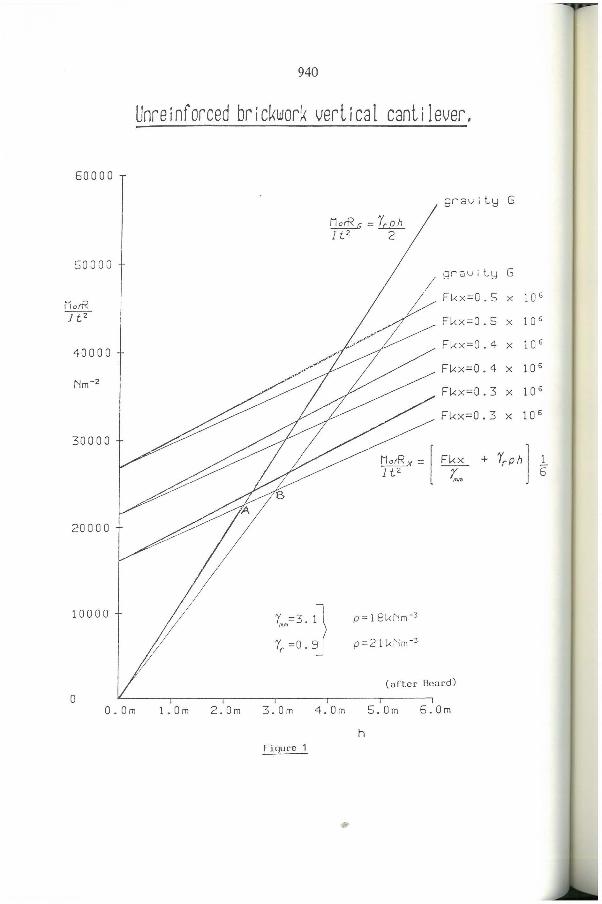
Gravity Design versus Flexure + Gravity Fig 1 shows a plot of the two different methods.
It demonstrates that:-
1. When H> ~ 3.5 - 4.5 M the wall eould be safe even if the flexural bond is zero.
2. When H<~ 2 - 3 m the eontrary is true and the wall eannot be justified by gravity design if it was originally designed using flexure plus gravity and the flexural bond beeomes zero.
An understanding of this relationship is important. For example it ean be seen that for a small wall (to the left of A, Fig 1), designed on the basis of flexure, it eannot be justified if a membrane type DPe is ineorporated on site. For tal ler walls to the right of B, ineluding sue h a DPe (by design or by default) does not influenee the stability of the wall. It is still stable with no flexural bond present.
Table 1 presents this information in a different manner. It shows the thiekness of a single leaf wall required for a given height and basie windspeed for both the 'gravity plus flexure' and 'gravity' only design methods.
940
Unreinforced brickwork verlical canlilever.
60000
gravil~ G
MorR G = Y( oh lU 2
50000 orc;vil~ G
/~
iíotT< FL<x=0.5 x 10 6
Jt2 FL<x=0.5 x 10 6
40000 FL<x=0.4 X 10 6
Fl-<x=0.4 X 10 6
Nm-2
Fl-<x=0.3 X 10 6
30000
~ Fl-<x=0.3 X 10 6
~t~X = [Fl-<X + YrPh] 1 ~ 5
20000
10000 p= 18L<Nm-3
p =21 L<l'lm- 3
Ymm=3.1J Y( =0.9
(aftcr Bcard)
o O.Om 100m 2.0m 3.0m 4.0m 5.0m 5.0m
h Figure 1
•

941 •
TABLE Thickness of Single Leaf (in mm ) For Various Heights and Wind Speeds
h Uncracked Section Cracked Section (m) Basic Windspeed m/sec Basic Windspeed m/sec
38 40 42 44 46 48 50 52 38 40 42 44 46 48 50 52
1.0 134 141 148 155 162 169 176 183 178 188 197 206 216 225 235 244
1.3 162 171 179 188 196 205 213 222 200 211 221 232 242 252 263 274
1.6 189 199 209 219 229 239 249 259 219 231 242 254 266 277 289 300
1. 9 215 226 238 249 260 272 283 294 237 250 262 275 287 300 312 325
2 . 2 240 253 265 278 290 303 316 328 253 267 281 294 307 321 334 348
2.5 264 278 292 305 319 333 347 361 270 284 298 312 326 340 355 369
2.8 287 302 317 332 347 362 377 392 284 299 314 329 344 359 374 389
3.1 336 353 371 389 406 424 442 459 324 341 359 376 393 410 427 444
3.4 359 378 397 416 435 453 472 491 339 357 375 393 411 428 446 464
3. 7 382 402 422 442 462 482 502 522 353 372 391 409 428 447 465 484
4.0 404 425 446 467 489 510 531 552 367 386 406 425 445 464 483 503
4.3 42 5 447 470 492 515 537 55 1 582 380 401 421 441 461 481 501 521
4.6 446 469 493 516 540 563 586 610 393 414 435 456 477 497 518 539
4.9 466 491 515 540 564 589 613 638 406 428 449 471 492 513 535 556
942
TABLE 2 Survey Results - Sheet 1 of 2
Wall No. Height Thick- DPC Aspect Remarks Status
No . 1
No. 2
No. 3
No. 4
No . 5
No . 6
No . 7
No. 8
No. 9
No. 10
No . 11
M* ness mm
1.3 (0.94 )
2. 25 (0.97)
2.25
(0.80 )
1. 9 (0.94)
2 . 25 (0 . 84 )
2.25 (0.84 )
5.0 (1.94 )
1 .25 (0 . 94 )
1.8 (0 . 94 )
3 m (1 . 94 )
1 . 9 m (1.94 )
150 No Faced open country
102 . 5 No Parapet on roof
Concrete block, 300 x 400 piers at 1.5 m c/c
200 x 400 piers at 1.75 m c/c
Failed
Failed
102.5 No Curved wall Open slits in Failed between wall, 200 sq buildings piers at 1.5 m c/ c
250 No Between Buildings
102.5 No By CarPark
102.5 No Between Buildings
215 No Between buildings
Cavity with Failed concrete coping on DPC
300 returns at Failed 2 m c/ c
200 sq piers at Failed 1-1 . 5 c/ c
200 x 300 piers Failed at ends of 1.5 m sections
102 . 5 No Fenced open 200 sq piers at Failed
102.5
215
215
space 1.5 m c/ c
No Playground wall
? Faced open country
No Between buildings
200 x 300 piers Failed at 2 m c/ c
Very open country Failed
300 x 400 piers at Failed 2.5 m Max. 3 second gust at 25 m/ s
* Figures in brackets denote height to which the wall can be justified on the information available.
"

• 943
TABLE 2 Sheet 2 of 2
Wall No. Height Thick- DPC Aspect Remarks Status M* ness mm
No . 12 2.1 102.5 No ? 9 m long, 215 sq Failed (0.94) piers of 3m c/ c
No. 13 2.0 102.5 3 Cs Enclosing 1.5 m length, Failed (0 .84 ) Eng. courtyard returned 215 at
bk. on one ends between side vision panels
No. 14 1.8 102.5 No Encloses 215 sq piers at Failed (0.94) a garden 3 m c/c
suburban
No. 15 1.8 102.5 Yes Encloses Cracked and Failed (0.85) a garden deflected visibly
suburban in wind, failed shortly after
No. 16 1.8 102 .5 Yes Exposed 102.5 stagger at Part (0 .95 ) 3170 c/c calcium failed/
silicate bricks rest at risk
No. 17 1.8 102.5 No Exposed 340 piers at 6m Failed (0.89) c/c Wall fa iled
shortly after site was cleared
No. 18 1.8 102.5 ? Enclosed No further infor- Failed (0 .89 ) a garden mation known
No . 19 1. 75 102.5 No Enclosed 3 m long, 215 piers Failed (0.89) a garden at ends
No. 20 2.5 215 Yes Garden No piers, still At Risk (1.85 ) Wall okay
* As note on Sheet ? Unknown

944
Analysis of Data Despite calls for information on wall collapses ma de in the columns of the relevant professional journals and magazines, the response was small . Indeed the majority of collapses were 'found' by the personal effor ts of the authors. Having regard to the present prevalence for litigation this is perhaps not surprising: on the other hand the gaining of professional knowledge through unsuccessful structures does seem an important and valuable are a from which better design practice will resulto
The data so collected and shown in Table 1 consisted, predominantly, of failures in the South East of England. The thickness of most of the walls were 102.5 mm or 215 mm. Theoretical calculations were ma de to test the maximum height to which the wall sections could be justified using wind speeds of 38 m/ second and 42 m/ second. The actual height was then compared with the theoretical requirements .
The following general points emerge:
In alI cases the failed walls could not be justified using the current practice for the design of the walls . In two instances (wa lls 16 & 20) walls which could not be justified remained standing . These are vulnerable, in the authors' view, when they experience the next 'blow' from the right direction. One of these walls (no. 16) had already collapsed in part and had been rebuilt, using'the same section but to a much reduced height.
There were two cases of walls wh i ch had not yet failed but which were potentially dangerous since the thickness of the walls with DPe at the base could not be justified for the height.
There are a number of reasons why these walls have not collapsed; they include:-
a ) The full design wind force may not have been experienced by the wa 11s as yet.
b) The surrounding buildings may be offering considerable shelter to the walls thus limiting the maximum value of wind pressure which is likely to act to a lower value than the current wind code.
c ) The aspect of the walls (on which there was no information) may be such that the walls do not receive the high wind pressure assumed in the calculations.
Wall No 17 had stood for some years. It was sheltered by a block of buildings and failed shortly after this block was demolished.
One of the walls which could not be included in the analysis because of lack of available details had collapsed twice and been rebuilt twice. It was only when it collapsed for the third time that advice was sought and the section found to be wanting for the wind pressure to which it was subjected and for the height required.
•
945 • CONCLUSIDNS
This limited study has not demonstrated that wall collapses are occurring when the walls are designed al10wing for f1exure and gravity. On the contrary the failed walls were all toa high for the section adopted and/or the OPC condition negated the basis of designo Since knowledge on the method of design is available, this 1imited study suggests that in many cases wa11s are not designed but merely constructed without any attempt to check their structural adequacy.
There would appear to be a need to a1ert the construction industry to the need for free-standing walls to be "designed" or at least checked for stabi1ity. Although BOA publication "Oesign of Freestanding Walls" is a useful and authoritative document, consideration shou1d be given to the production of a briefer less technical document on the design of smal1 free standing walls for builders/deve1opers. There would require to be clearly stated 1imitations on the use of such a brief documento When a proposed wall goes beyond any of the 1imitations set, a more complete analysis can be done.
It is clear that undue re1iance is being placed on the efficiency of tee-section piers in freestanding walls. These are general1y not sufficient to reduce the tensile stresses in the masonry except 10ca1ly to the piers. In any case they are only efficient in one direction name1y where the piers are on the lee-ward face af the wal1s.
Final1y, the difficu1ty in obtaining information on fai1ures was most acute. The authors are conscious of the value of 'learning from mistakes' and yet there is difficulty in accessing information. This wou1d appear to be an area which needs to be addressed.