A Dialog engine Metamodel for the Transformation-Driven ... · A Dialog Engine Metamodel for the...
20
SCIENTIFIC PAPERS, UNIVERSITY OF LATVIA, 2010. Vol. 756 COMPUTER SCIENCE AND INFORMATION TECHNOLOGIES 151–170 P. A Dialog engine Metamodel for the Transformation-Driven Architecture 1 Sergejs Kozlovics University of Latvia, Faculty of Computing, Raina bulv. 19, Riga, LV-1586, Latvia Institute of Mathematics and Computer Science, University of Latvia Raina bulv. 29, Riga, LV-1459, Latvia [email protected] Many metamodel-based tools provide only limited features for specifying dialog windows by means of the metamodel. Is there a way of specifying complex dialogs while still using the metamodel-based ap-proach? The metamodel proposed in this paper permits specifying rather complex dialogs in a simple and intuitive way. It has been successfully used within the context of the transformation-driven architecture (TDA). Keywords: dialogs, GUI, dialog engine, TDA, transformation-driven architecture. 1 Introduction It is hard to imagine a graphical tool without a graphical user interface (GUI). Classical dialog boxes with input fields and buttons are well-known and accus- tomed. We will not invent the wheel in this paper; we concentrate on already familiar dialog windows. We present a simple yet expressive metamodel for describing such dialogs and comment on the corresponding engine for handling dialogs specified by means of that metamodel. Since this is a metamodel, it may be used in the world of model transformations. Our metamodel has already been successfully used with the transformation-driven architecture [1], which is a system-building approach that incorporates model transformations and metamodels with their engines. The above mentioned dialog metamodel is the main contribution of this paper. The metamodel has been developed in such a way that, given an instance of it, the dialog engine is able to automatically create the real dialog box at runtime and to show it to the user. One of the important features of the metamodel is the possibility to specify the layout of dialog elements. If we sketch a dialog box on a sheet of paper, we usually do not bother about exact coordinates, but we think about the layout and grouping of components and aesthetics. The same kind of layout information is expected in instances of the proposed metamodel. One may be interested whether the metamodel uses exact sizes and/or co-ordinates for components. A dilemma arises: on the one hand, exact coordinates may guide the dialog engine on the desired sizes of components in case the components with the default (or in some way calculated) sizes are not aesthetic. On the other hand, the system font 1 This research is partially supported by European Social Fund.
Transcript of A Dialog engine Metamodel for the Transformation-Driven ... · A Dialog Engine Metamodel for the...

SCIENTIFIC PAPERS, UNIVERSITy OF LATVIA, 2010. Vol. 756COMPUTER SCIENCE AND INFORMATION TEChNOLOGIES 151–170 P.
S. KozlovicsA Dialog engine Metamodel for the Transformation-Driven Architecture
A Dialog engine Metamodel for the Transformation-Driven Architecture1
Sergejs KozlovicsUniversity of Latvia, Faculty of Computing, Raina bulv. 19, Riga, LV-1586, Latvia
Institute of Mathematics and Computer Science, University of LatviaRaina bulv. 29, Riga, LV-1459, Latvia
Many metamodel-based tools provide only limited features for specifying dialog windows by means of the metamodel. Is there a way of specifying complex dialogs while still using the metamodel-based ap-proach? The metamodel proposed in this paper permits specifying rather complex dialogs in a simple and intuitive way. It has been successfully used within the context of the transformation-driven architecture (TDA).
Keywords: dialogs, GUI, dialog engine, TDA, transformation-driven architecture.
1 IntroductionIt is hard to imagine a graphical tool without a graphical user interface (GUI).
Classical dialog boxes with input fields and buttons are well-known and accus-tomed. We will not invent the wheel in this paper; we concentrate on already familiar dialog windows. We present a simple yet expressive metamodel for describing such dialogs and comment on the corresponding en gine for handling dialogs specified by means of that metamodel. Since this is a metamodel, it may be used in the world of model transformations. Our metamodel has already been successfully used with the transformation-driven architecture [1], which is a system-building approach that incorporates model transformations and metamodels with their engines.
The above mentioned dialog metamodel is the main contribution of this paper. The metamodel has been developed in such a way that, given an instance of it, the dialog engine is able to automatically create the real dialog box at runtime and to show it to the user. One of the important features of the metamodel is the possibility to specify the layout of dialog elements. If we sketch a dialog box on a sheet of paper, we usually do not bother about exact coordinates, but we think about the layout and grouping of components and aesthetics. The same kind of layout information is expected in instances of the proposed metamodel.
One may be interested whether the metamodel uses exact sizes and/or co-ordinates for components. A dilemma arises: on the one hand, exact coordinates may guide the dialog engine on the desired sizes of compo nents in case the components with the default (or in some way calculated) sizes are not aesthetic. On the other hand, the system font
1 This research is partially supported by European Social Fund.
152 Computer SCienCe and information teChnologieS
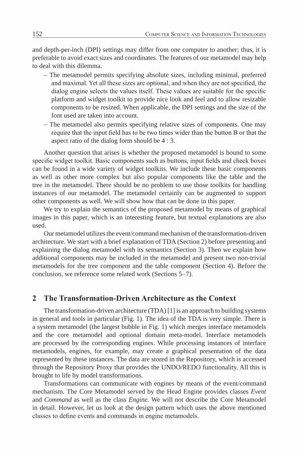
and depth-per-inch (DPI) settings may differ from one computer to another; thus, it is preferable to avoid exact sizes and coordinates. The features of our metamodel may help to deal with this dilemma.
− The metamodel permits specifying absolute sizes, including minimal, preferred and maximal. Yet all these sizes are optional, and when they are not specified, the dialog engine selects the values itself. These values are suitable for the specific platform and widget toolkit to provide nice look and feel and to allow resizable components to be resized. When applicable, the DPI settings and the size of the font used are taken into account.
− The metamodel also permits specifying relative sizes of components. One may require that the input field has to be two times wider than the button B or that the aspect ratio of the dialog form should be 4 : 3.
Another question that arises is whether the proposed metamodel is bound to some specific widget toolkit. Basic components such as buttons, input fields and check boxes can be found in a wide variety of widget toolkits. We include these basic components as well as other more complex but also popular components like the table and the tree in the metamodel. There should be no problem to use those toolkits for handling instances of our metamodel. The metamodel certainly can be augmented to support other components as well. We will show how that can be done in this paper.
We try to explain the semantics of the proposed metamodel by means of graphical images in this paper, which is an interesting feature, but textual explanations are also used.
Our metamodel utilizes the event/command mechanism of the transformation-driven architecture. We start with a brief explanation of TDA (Section 2) before presenting and explaining the dialog metamodel with its semantics (Section 3). Then we explain how additional components may be included in the metamodel and present two non-trivial metamodels for the tree component and the table component (Section 4). Before the conclusion, we reference some related work (Sections 5−7).
2 The Transformation-Driven Architecture as the ContextThe transformation-driven architecture (TDA) [1] is an approach to building systems
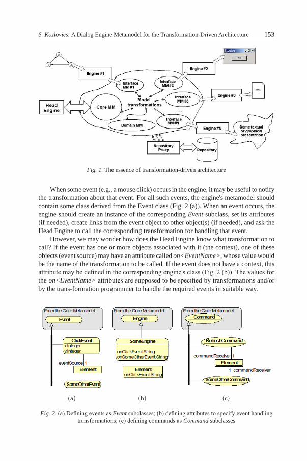
in general and tools in particular (Fig. 1). The idea of the TDA is very simple. There is a system metamodel (the largest bubble in Fig. 1) which merges interface metamodels and the core metamodel and optional domain meta-model. Interface metamodels are processed by the corresponding engines. While processing instances of interface metamodels, engines, for example, may create a graphical presentation of the data represented by these instances. The data are stored in the Repository, which is accessed through the Repository Proxy that provides the UNDO/REDO functionality. All this is brought to life by model transformations.
Transformations can communicate with engines by means of the event/command mechanism. The Core Metamodel served by the head En gine provides classes Event and Command as well as the class Engine. We will not describe the Core Metamodel in detail. however, let us look at the design pattern which uses the above mentioned classes to define events and commands in engine metamodels.
153S. Kozlovics. A Dialog Engine Metamodel for the Transformation-Driven Architecture
When some event (e.g., a mouse click) occurs in the engine, it may be useful to notify the transformation about that event. For all such events, the engine's metamodel should contain some class derived from the Event class (Fig. 2 (a)). When an event occurs, the engine should create an instance of the corresponding Event subclass, set its attributes (if needed), create links from the event object to other object(s) (if needed), and ask the head Engine to call the corresponding transformation for handling that event.
however, we may wonder how does the head Engine know what transformation to call? If the event has one or more objects associated with it (the context), one of these objects (event source) may have an attribute called on<EventName>, whose value would be the name of the transformation to be called. If the event does not have a context, this attribute may be defined in the corresponding engine's class (Fig. 2 (b)). The values for the on<EventName> attributes are supposed to be specified by transformations and/or by the trans-formation programmer to handle the required events in suitable way.
Fig. 1. The essence of transformation-driven architecture
Fig. 2. (a) Defining events as Event subclasses; (b) defining attributes to specify event handling transformations; (c) defining commands as Command subclasses
Fig. 1. The essence of the Transformation-Driven Architecture.
simple. There is a system metamodel (the big cloud in Fig. 1), which merges in-terface metamodels along with the core metamodel and optional domain meta-model. Interface metamodels are “understood” by the corresponding engines.While processing instances of interface metamodels, engines, for example, maycreate a graphical presentation of the data represented by these instances. Thedata are stored in the Repository, which is accessed through the RepositoryProxy that provides the UNDO/REDO functionality. All these is “brought tolive” by model transformations.
Transformations can communicate with engines by means of theevent/command mechanism. Thus, the Core Metamodel served by the Head En-gine provides classes Event and Command as well as the class Engine. We won’tgo into the detail about the Core Metamodel. However, let’s look at a designpattern, which uses just mentioned classes, for defining events and commands inengines’ metamodels.
When some event (e.g., a mouse click) occurs in the engine, it may be usefulto notify the transformation about that event. For all such events the engine’smetamodel should contain some class derived from the Event class (Fig. 2(a)).When an event occurs, the engine should create an instance of the correspondingEvent subclass, set its attributes (if needed), create links from the event objectto other object(s) (if needed), and ask the Head Engine to call the correspondingtransformation for handling that event.
However, someone may be wondered how does the Head Engine know whattransformation to call? If the event has one or more objects associated with it(the context), then one of these objects (event source) may have an attributecalled on<EventName>, whose value would be the name of the transformationto be called. If the event doesn’t have a context, this attribute may be defined in
(a) (b) (c)
Fig. 2. (a) Defining events as Event subclasses. (b) Defining attributes for specifyingevent handling transformations. (c) Defining commands as Command subclasses.
the corresponding engine’s class (Fig. 2(b)). The values for the on<EventName>attributes are supposed to be specified by transformations and/or by the trans-formation programmer to handle the required events in the suitable way.
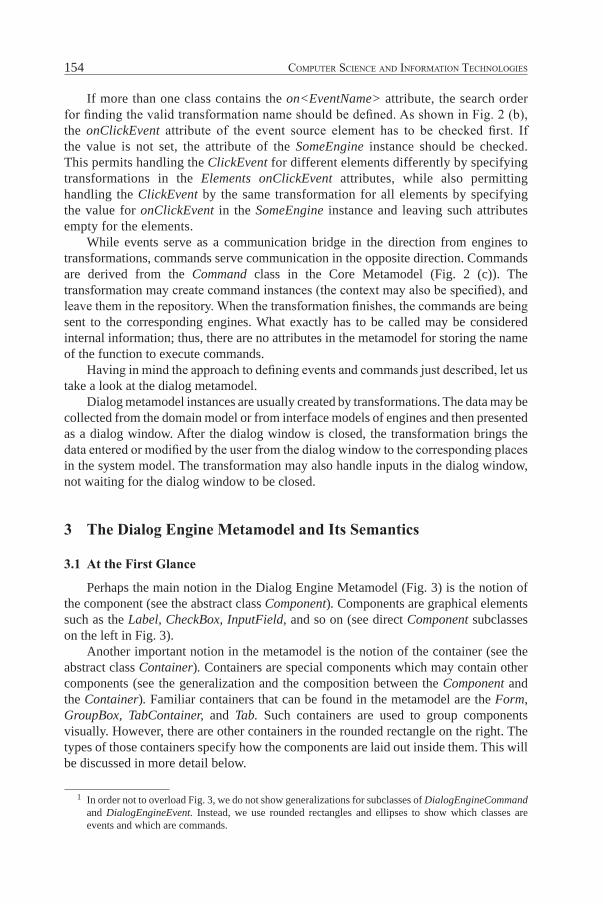
If more than one class contains the on<EventName> attribute, the searchorder for finding the valid transformation name should be defined. For Fig. 2(b)we may say that the onClickEvent attribute of the event source element has tobe checked first. If the value is not set, then the attribute of the SomeEngineinstance should be checked. This allows handling the ClickEvent for different el-ements differently by specifying transformations in the Element’s onClickEventattributes, while also allowing handling the ClickEvent by the same transforma-tion for all elements by specifying the value for onClickEvent in the SomeEngineinstance and leaving such attributes empty for the elements.
While events serve as a communication bridge in the direction from enginesto transformations, commands are used in the opposite direction. Commandsare derived from the Command class in the Core Metamodel (Fig. 2(c)). Thetransformation may create command instances (also, the context may be spec-ified), and leave them in the repository. When the transformation finishes, thecommands are being sent to the corresponding engines. What exactly has to becalled may be considered internal information, thus there are no attribute in themetamodel for storing the name of the function for executing commands.
Having in mind the approach for defining events and commands just de-scribed, let’s take a look at the dialog metamodel.
Dialog metamodel instances are usually created by transformations. The datamay be collected from the domain model or from interface models of engines andthen presented as a dialog window. After the dialog is closed, the transformationbrings the data entered or modified by the user from the dialog window to thecorresponding places in the system model. The transformation may also handleinputs in the dialog window “on-line”, not waiting for the dialog to be closed.
154 Computer SCienCe and information teChnologieS
If more than one class contains the on<EventName> attribute, the search order for finding the valid transformation name should be defined. As shown in Fig. 2 (b), the onClickEvent attribute of the event source element has to be checked first. If the value is not set, the attribute of the SomeEngine instance should be checked. This permits handling the ClickEvent for different el ements differently by specifying transformations in the Elements onClickEvent attributes, while also permitting handling the ClickEvent by the same transformation for all elements by specifying the value for onClickEvent in the SomeEngine instance and leaving such attributes empty for the elements.
While events serve as a communication bridge in the direction from engines to transformations, commands serve communication in the opposite direction. Commands are derived from the Command class in the Core Metamodel (Fig. 2 (c)). The transformation may create command instances (the context may also be specified), and leave them in the repository. When the transformation finishes, the commands are being sent to the corresponding engines. What exactly has to be called may be considered internal information; thus, there are no attributes in the metamodel for storing the name of the function to execute commands.
Having in mind the approach to defining events and commands just described, let us take a look at the dialog metamodel.
Dialog metamodel instances are usually created by transformations. The data may be collected from the domain model or from interface models of engines and then presented as a dialog window. After the dialog window is closed, the transformation brings the data entered or modified by the user from the dialog window to the corresponding places in the system model. The transformation may also handle inputs in the dialog window, not waiting for the dialog window to be closed.
3 The Dialog engine Metamodel and Its Semantics
3.1 At the First Glance
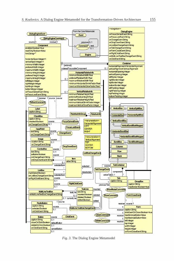
Perhaps the main notion in the Dialog Engine Metamodel (Fig. 3) is the notion of the component (see the abstract class Component). Components are graphical elements such as the Label, CheckBox, InputField, and so on (see direct Component subclasses on the left in Fig. 3).
Another important notion in the metamodel is the notion of the container (see the abstract class Container). Containers are special components which may contain other components (see the generalization and the composition between the Component and the Container). Familiar containers that can be found in the metamodel are the Form, GroupBox, TabContainer, and Tab. Such containers are used to group components visually. however, there are other containers in the rounded rectangle on the right. The types of those containers specify how the components are laid out inside them. This will be discussed in more detail below.
1 In order not to overload Fig. 3, we do not show generalizations for subclasses of DialogEngineCommand and DialogEngineEvent. Instead, we use rounded rectangles and ellipses to show which classes are events and which are commands.
155S. Kozlovics. A Dialog Engine Metamodel for the Transformation-Driven Architecture
Fig. 3. The Dialog Engine MetamodelFig. 3. The Dialog Engine Metamodel
156 Computer SCienCe and information teChnologieS
There are certain events and commands that may be assigned to components. As we can see at the top of Fig. 3, the Dialog Engine Metamodel follows the design pattern mentioned in Sect. 2. Each DialogEngineCommand and DialogEngineEvent 1 has a context which must include a component to which the command/event refers to; see roles source and receiver of the class Component. For instance, a ClickEvent may be linked to a Button or to a RadioButton.
The class DialogEngine contains on<EventName> attributes for specifying event handling transformations. Note that components also have such attributes for the events they may refer to; see, for example, the Button's onClick-Event attribute.
After the first glance at the metamodel, let us look closer at the basic components and the layout specification.
3.2 The Basic Components with Their events and Commands
We start from the features common to all components.There is a readOnly attribute in the Component class. Different compo nents may
implement their semantics differently, but the main meaning is that if readOnly= true, the user is not able to change the value of the component.
The readOnly attribute is recursive, i.e., its value applies to the component itself, and, in case the component is a container, to the child components, and so on. In case another value is specified for some child/descendant, that new value is propagated recursively. Such recursive semantics of the readOnly attribute may be useful when a non-editable form has to be shown, for instance, in read-only mode, or when the user does not have access to change the values in the form. It suffices to specify readOnly= true only for the Form instance, leaving readOnly undefined for all other components in that form.
The Component class also has two events: the FocusGainedEvent and the FocusLostEvent. These events occur when the component gains or loses the input focus. Not all components may produce such events (e.g., the Label does not).
Furthermore, a RefreshCommand may be associated with the component. The semantics of this command is to re-read value(s) for the component from the repository.2 If the component is a container, then, besides refreshing the compo nent itself, the RefreshCommand reloads its descendants — one may think of it as if the previous descendants have been deleted, and the current descendants have been added.
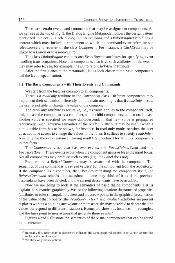
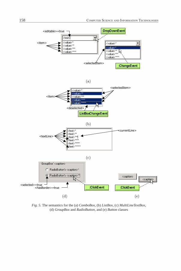
Now we are going to look at the semantics of basic dialog components. Let us explain the semantics graphically. We use the following notation: the names of properties (attributes or roles) in angular brackets and the arrow points to the graphical presentation of the value of that property (the <caption>, <text> and <value> attributes are present at places without a pointing arrow; one or more asterisks may be added to denote that the values correspond to different instances). Events are shown as instances in rectangles, and the lines point to user actions that generate these events.3
Figures 4 and 5 illustrate the semantics of the visual components that can be found in the metamodel.
2 Internally this action may be performed either on the same graphical control or on a new control that replaces the previous one.
3 We show only mouse actions.
157S. Kozlovics. A Dialog Engine Metamodel for the Transformation-Driven Architecture
(a)
(b)
(c) (d) (e)
(f)
Fig. 4. The semantics for the (a) Form, (b) TabContainer and Tab, (c) Label, (d)CheckBox, (e) InputField and (f) Image classes.
Fig. 4. The semantics for the (a) Form, (b) TabContainer and Tab, (c) Label, (d) CheckBox, (e) InputField and (f) Image classes
158 Computer SCienCe and information teChnologieS
(a)
(b)
(c)
(d) (e)
Fig. 5. The semantics for the (a) ComboBox, (b) ListBox, (c) MultiLineTextBox, (d)GroupBox and RadioButton, and (e) Button classes.
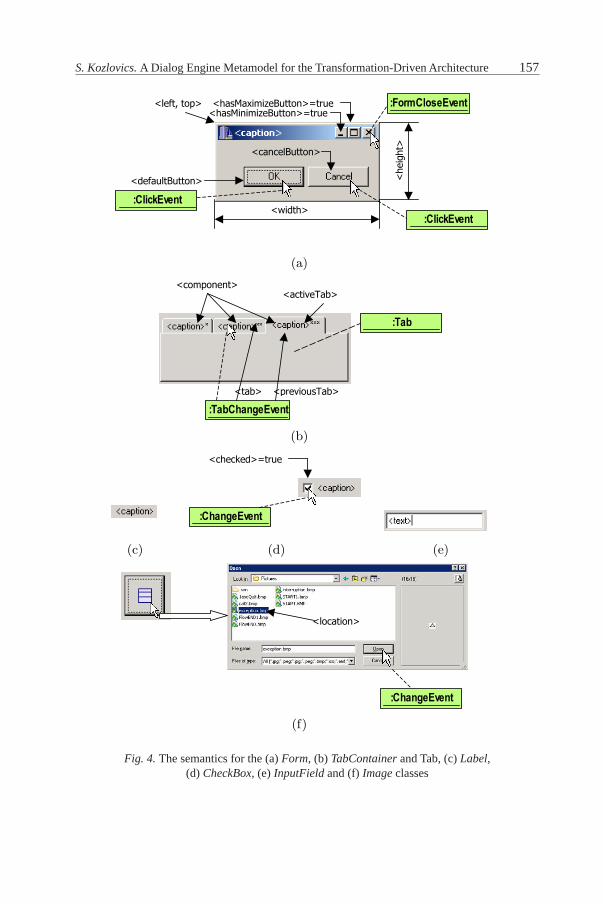
Fig. 5. The semantics for the (a) ComboBox, (b) ListBox, (c) MultiLineTextBox, (d) GroupBox and RadioButton, and (e) Button classes
159S. Kozlovics. A Dialog Engine Metamodel for the Transformation-Driven Architecture
Let us explain some aspects not explicitly shown in Fig. 4 and 5.– The semantics for the event produced when the user clicks the “close” ("X")
button of the form (Fig. 4 (a)) is as follows: if <clickEventOnClose> = false or there is neither the “cancel”, nor “default” button4, the FormCloseEvent is generated. Otherwise, a ClickEvent for the “cancel” button is generated. In case there is no “cancel” button, a ClickEvent is attached to the “default” button (this is useful when the form contains only one "OK" button).
– The MultiLineTextBox (Fig. 5 (c)) continues to be linked to those TextLines which have already been deleted from the screen and have deleted = true. This may be useful when some actions have to be performed after some TextLines have been deleted, but these TextLines are linked to other objects.
– RadioButtons (Fig. 5 (d)) usually are grouped together. Only one of the radio buttons in the group may be selected at the same time. We assume that the group consists of the radio buttons that are in the same visible container.5
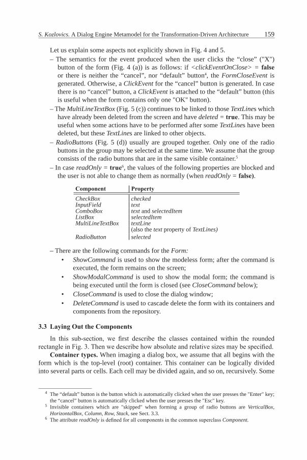
– In case readOnly = true6, the values of the following properties are blocked and the user is not able to change them as normally (when readOnly = false).
Component PropertyCheckBox checkedInputField textComboBox text and selectedItemListBox selectedItemMultiLineTextBox textLine
(also the text property of TextLines)RadioButton selected
– There are the following commands for the Form:• ShowCommand is used to show the modeless form; after the command is
executed, the form remains on the screen;• ShowModalCommand is used to show the modal form; the command is
being executed until the form is closed (see CloseCommand below);• CloseCommand is used to close the dialog window;• DeleteCommand is used to cascade delete the form with its containers and
components from the repository.
3.3 Laying Out the Components
In this sub-section, we first describe the classes contained within the rounded rectangle in Fig. 3. Then we describe how absolute and relative sizes may be specified.
Container types. When imaging a dialog box, we assume that all begins with the form which is the top-level (root) container. This container can be logically divided into several parts or cells. Each cell may be divided again, and so on, recursively. Some
4 The “default” button is the button which is automatically clicked when the user presses the "Enter" key; the “cancel” button is automatically clicked when the user presses the "Esc" key.
5 Invisible containers which are "skipped" when forming a group of radio buttons are VerticalBox, HorizontalBox, Column, Row, Stack, see Sect. 3.3.
6 The attribute readOnly is defined for all components in the common superclass Component.
160 Computer SCienCe and information teChnologieS
cells are occupied by visible components or containers, while other are simple invisible "frames" or "borders".
Each cell has its width and height. however, if the cell is occupied by a (visible) scrollable container, there are also interior width and interior height that correspond to the scrollable area where the child components are placed.
In the metamodel, the notion of the cell is represented by the Container class. The way the cell (or the container) is divided into other cells determines the type of the container.
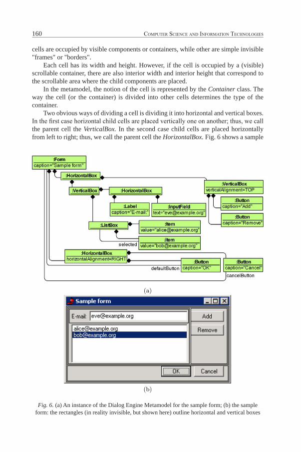
Two obvious ways of dividing a cell is dividing it into horizontal and vertical boxes. In the first case horizontal child cells are placed vertically one on another; thus, we call the parent cell the VerticalBox. In the second case child cells are placed horizontally from left to right; thus, we call the parent cell the HorizontalBox. Fig. 6 shows a sample
Fig. 6. (a) An instance of the Dialog Engine Metamodel for the sample form; (b) the sample form: the rectangles (in reality invisible, but shown here) outline horizontal and vertical boxes
(a)
(b)
Fig. 6. (a) An instance of the Dialog Engine Metamodel for the sample form. (b) Thesample form: the rectangles (in reality invisible, but shown here) outline horizontal andvertical boxes.
(a) (b)
Fig. 7. Examples of (a) a horizontally scrollable box and (b) a vertically scrollable box.
161S. Kozlovics. A Dialog Engine Metamodel for the Transformation-Driven Architecture
form which uses horizontal and vertical boxes for the layout.7 The form itself is a vertical box as well. A container of some other type may be placed on the form when needed, thus converting the form from a vertical box to the other container type.
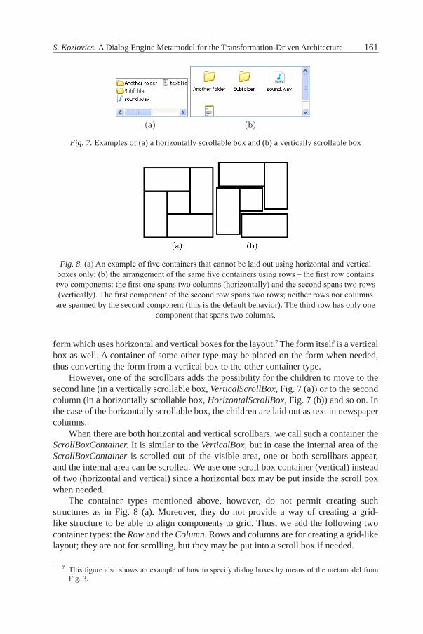
however, one of the scrollbars adds the possibility for the children to move to the second line (in a vertically scrollable box, VerticalScrollBox, Fig. 7 (a)) or to the second column (in a horizontally scrollable box, HorizontalScrollBox, Fig. 7 (b)) and so on. In the case of the horizontally scrollable box, the children are laid out as text in newspaper columns.
When there are both horizontal and vertical scrollbars, we call such a con tainer the ScrollBoxContainer. It is similar to the VerticalBox, but in case the internal area of the ScrollBoxContainer is scrolled out of the visible area, one or both scrollbars appear, and the internal area can be scrolled. We use one scroll box container (vertical) instead of two (horizontal and vertical) since a horizontal box may be put inside the scroll box when needed.
The container types mentioned above, however, do not permit creating such structures as in Fig. 8 (a). Moreover, they do not provide a way of creating a grid-like structure to be able to align components to grid. Thus, we add the following two container types: the Row and the Column. Rows and columns are for creating a grid-like layout; they are not for scrolling, but they may be put into a scroll box if needed.
7 This figure also shows an example of how to specify dialog boxes by means of the metamodel from Fig. 3.
Fig. 7. Examples of (a) a horizontally scrollable box and (b) a vertically scrollable box
Fig. 8. (a) An example of five containers that cannot be laid out using horizontal and vertical boxes only; (b) the arrangement of the same five containers using rows – the first row contains two components: the first one spans two columns (horizontally) and the second spans two rows (vertically). The first component of the second row spans two rows; neither rows nor columns are spanned by the second component (this is the default behavior). The third row has only one
component that spans two columns.
(a)
(b)
Fig. 6. (a) An instance of the Dialog Engine Metamodel for the sample form. (b) Thesample form: the rectangles (in reality invisible, but shown here) outline horizontal andvertical boxes.
(a) (b)
Fig. 7. Examples of (a) a horizontally scrollable box and (b) a vertically scrollable box.
162 Computer SCienCe and information teChnologieS
We do not add the container for representing the table. We assume that neigh-boring rows (or columns) form the necessary grid-like structure, i.e., the compo-nents of neighboring rows (or columns) are aligned to grid. Thus, their parent container may be considered to be a container representing the table.
however, having a grid, we should allow the components to be able to span several rows and/or columns (see attributes horizontalSpan and verticalSpan of the Component class). This permits creating layout structures such as in Fig. 8.
One more container type is needed to implement the tabs. Since tabs occupy the same space, we think that the components are put one over another like cards. We introduce the Stack container, where all the children occupy the same space.
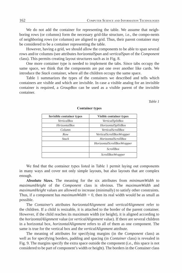
Table 1 summarizes the types of the containers we described and tells which containers are visible and which are invisible. In case a visible analog for an invisible container is required, a GroupBox can be used as a visible parent of the invisible container.
Table 1
Container types
Invisible container types Visible container typesVerticalBox VerticalSplitBox
HirizontalBox HorizontalSpllitBoxColumn VerticalScrollBox
Row VerticalScrollBoxWrapperStack HorizontalScrollBox
HorizontalScrollBoxWrapper
ScrollBox
ScrollBoxWrapper
We find that the container types listed in Table 1 permit laying out components in many ways and cover not only simple layouts, but also layouts that are complex enough.
Absolute Sizes. The meaning for the six attributes from minimumWidth to maximumHeight of the Component class is obvious. The maximumWidth and maximumHeight values are allowed to increase (minimally) to satisfy other constraints. Thus, if a component has maximumWidth = 0, then its real width would be as small as possible.
The Container's attributes horizontalAlignment and verticalAlignment refer to the children. If a child is resizable, it is attached to the border of the parent container. however, if the child reaches its maximum width (or height), it is aligned according to the horizontalAlignment value (or verticalAlignment value). If there are several children in a horizontal box, horizontalAlignment refers to all of them as one component. The same is true for the vertical box and the verticalAlignment attribute.
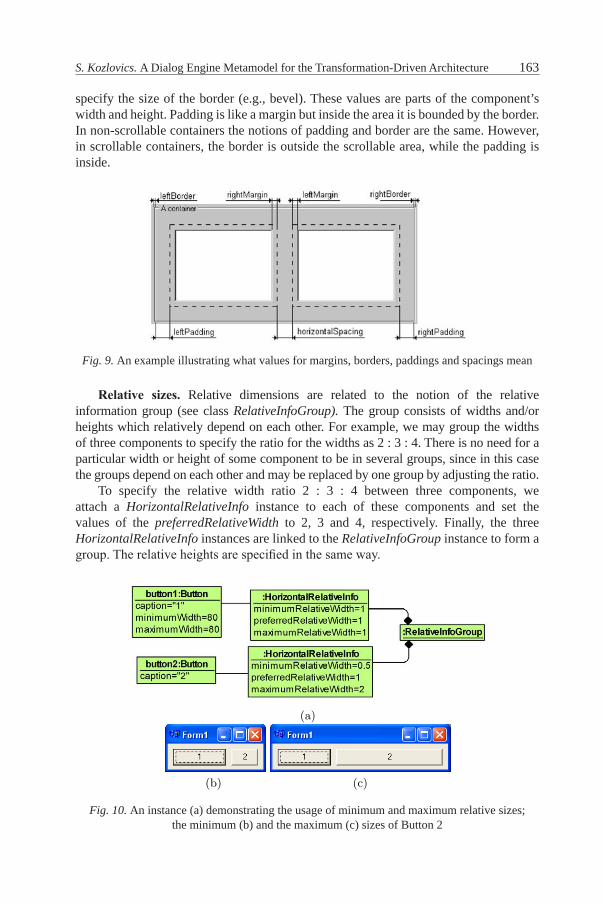
The meaning of attributes for specifying margins (in the Component class) as well as for specifying borders, padding and spacing (in Container class) is revealed in Fig. 9. The margins specify the extra space outside the component (i.e., this space is not considered to be part of component’s width or height). The borders in the Container class
163S. Kozlovics. A Dialog Engine Metamodel for the Transformation-Driven Architecture
specify the size of the border (e.g., bevel). These values are parts of the component’s width and height. Padding is like a margin but inside the area it is bounded by the border. In non-scrollable containers the notions of padding and border are the same. however, in scrollable containers, the border is outside the scrollable area, while the padding is inside.
Fig. 9. An example illustrating what values for margins, borders, paddings and spacings mean
Relative sizes. Relative dimensions are related to the notion of the relative information group (see class RelativeInfoGroup). The group consists of widths and/or heights which relatively depend on each other. For example, we may group the widths of three components to specify the ratio for the widths as 2 : 3 : 4. There is no need for a particular width or height of some component to be in several groups, since in this case the groups depend on each other and may be replaced by one group by adjusting the ratio.
To specify the relative width ratio 2 : 3 : 4 between three components, we attach a HorizontalRelativeInfo instance to each of these components and set the values of the preferredRelativeWidth to 2, 3 and 4, respectively. Finally, the three HorizontalRelativeInfo instances are linked to the RelativeInfoGroup instance to form a group. The relative heights are specified in the same way.
Fig. 10. An instance (a) demonstrating the usage of minimum and maximum relative sizes; the minimum (b) and the maximum (c) sizes of Button 2
(a)
(b) (c)
Fig. 10. An instance (a) demonstrating the usage of minimum and maximum relativesizes. The minimum (b) and the maximum (c) sizes of button 2.
preferred ratio could not be met, the button 2 is allowed to be up to 2 timeswider or shorter than the button 1.
4 Adding Components: the Tree and the Table
In order to add a component to the Dialog Engine, two steps have to be per-formed.
1. Developing a metamodel for that component, where the component class isa direct or indirect subclass of Component.
2. Implementing the certain interface for the new component in order the DialogEngine could use the new component.
Let’s see the examples of the first step for the Tree and the VerticalTable com-ponents. Then we sketch the interface that has to be implemented to be able touse the new components within the dialog engine.
4.1 The Tree and the VerticalTable metamodels
Figures 11 and 12 depict the syntax and semantics for the Tree and VerticalTablecomponents. Note that these components are descendants of the Componentclass of the main dialog engine metamodel and events are descendants of theDialogEngineEvent (and, thus, also of Event) class.
Some comments on the Tree metamodel.
– The TreeNodeSelectEvent may have also a previous link, which denotes whattree node was selected last.
164 Computer SCienCe and information teChnologieS
The minimum and maximum relative width and height are useful in resizing. An example is given in Fig. 10. Button 1 is not resizable, and the width of Button 2 is preferred to be the same as of Button 1. however, if the preferred ratio cannot be achieved, Button 2 is allowed to be up to 2 times wider or shorter than Button 1.
4 Adding Components: the Tree and the TableIn order to add a component to the Dialog Engine, two steps have to be performed.1 Developing a metamodel for the component for which the component class is a
direct or indirect subclass of Component.2 Implementing a certain interface for the new component so that the Dialog
Engine could use the new component.Let us see the examples of the first step for the Tree and the VerticalTable com-
ponents. We outline the interface that has to be implemented to be able to use the new components within the dialog engine.
4.1 The Tree and the VerticalTable Metamodels
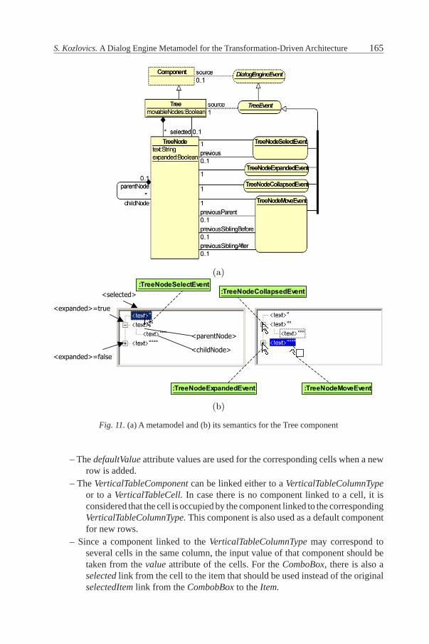
Figure 11 and 12 depict the syntax and semantics for the Tree and VerticalTable components. Note that these components are descendants of the Component class of the main dialog engine metamodel and events are descendants of the DialogEngineEvent (and thus also of Event) class. Some comments on the Tree metamodel follow.
– The TreeNodeSelectEvent may have a previous link which denotes which tree node was selected last.
– The TreeNodeMoveEvent occurs only when movableNodes attribute value of the Tree instance is true. The event is produced when the user drags one node over another (non-descendant) node (as in Fig. 11 (b)) or before or after some (non-descendant) node (in this case the position is shown as a line before or after the node). The links previousParent, previousSiblingBefore and previousSiblingAfter are created when necessary.
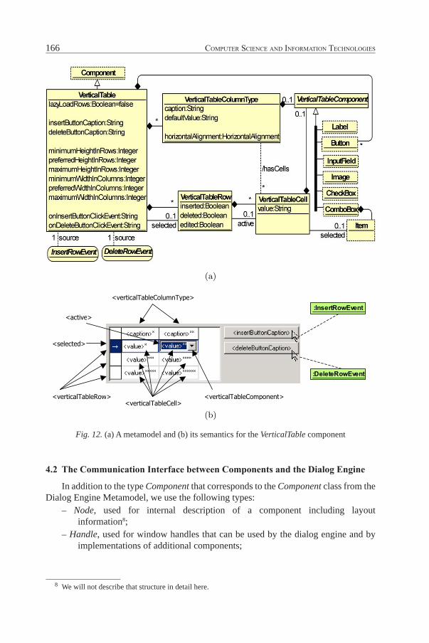
Some comments on the VerticalTable metamodel follow.– The lazyLoadRows attribute means that the table rows should not be loaded all
at once. Only visible rows have to be loaded first. Then, when the user scrolls the table, other rows may be loaded. Although this may speed up the table, not all cells are taken into consideration when preferred widths for the columns are calculated.
– The insertButtonCaption and deleteButtonCaption are useful only for non-read-only tables (i.e., when the superclass Component attribute readOnly value = false). These are captions for the buttons to insert and delete rows.
– Similarly to the MultiLineTextBox TextLines, the VerticalTableRow also has the inserted, edited and deleted attributes. The rows are not deleted from the repository automatically, but only marked by setting deleted = true.
– The hasCells association is derived since it may be calculated. The order of VerticalTableCells in a VerticalTableRow corresponds to the order of the VerticalTableColumnType of the VerticalTable.
165S. Kozlovics. A Dialog Engine Metamodel for the Transformation-Driven Architecture
Fig. 11. (a) A metamodel and (b) its semantics for the Tree component
– The defaultValue attribute values are used for the corresponding cells when a new row is added.
– The VerticalTableComponent can be linked either to a VerticalTableColumnType or to a VerticalTableCell. In case there is no component linked to a cell, it is considered that the cell is occupied by the component linked to the corresponding VerticalTableColumnType. This component is also used as a default component for new rows.
– Since a component linked to the VerticalTableColumnType may correspond to several cells in the same column, the input value of that component should be taken from the value attribute of the cells. For the ComboBox, there is also a selected link from the cell to the item that should be used instead of the original selectedItem link from the CombobBox to the Item.
(a)
(b)
Fig. 11. (a) A metamodel and (b) its semantics for the Tree component.
166 Computer SCienCe and information teChnologieS
4.2 The Communication Interface between Components and the Dialog engine
In addition to the type Component that corresponds to the Component class from the Dialog Engine Metamodel, we use the following types:
– Node, used for internal description of a component including layout information8;
– Handle, used for window handles that can be used by the dialog engine and by implementations of additional components;
Fig. 12. (a) A metamodel and (b) its semantics for the VerticalTable component
8 We will not describe that structure in detail here.
(a)
(b)
Fig. 12. (a) A metamodel and (b) its semantics for the VerticalTable component.
167S. Kozlovics. A Dialog Engine Metamodel for the Transformation-Driven Architecture
– Control, used as a pointer to a control (for example, to an object of the class implementing the component). The dialog engine passes this pointer back to the implementation of the component, for example, to lay out the control.
The interface is as follows.
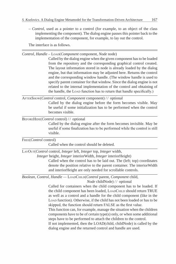
Control, Handle – load(Component component, Node node)Called by the dialog engine when the given component has to be loaded from the repository and the corresponding graphical control created. The layout information stored in node is already loaded by the dialog engine, but that information may be adjusted here. Returns the control and the corresponding window handle. (The window handle is used to specify parent container for that window. Since the dialog engine is not related to the internal implementation of the control and obtaining of the handle, the load function has to return that handle specifically.)
afterShow(Control control, Component component) / / optionalCalled by the dialog engine before the form becomes visible. May be useful if some initialization has to be performed when the control becomes visible.
Beforehide(Control control) / / optionalCalled by the dialog engine after the form becomes invisible. May be useful if some finalization has to be performed while the control is still visible.
free(Control control)Called when the control should be deleted.
layout(Control control, Integer left, Integer top, Integer width,Integer height, Integer interiorWidth, Integer interiorheight)
Called when the control has to be laid out. The (left; top) coordinates denote the position relative to the parent container. The interiorWidth and interiorheight are only needed for scrollable controls.
Boolean, Control, Handle — loadChild(Control parent, Component child,Node childNode) / / optional
Called for containers when the child component has to be loaded. If the child component has been loaded, loadChild should return TRUE as well as a control and a handle for the child component (like in the load function). Otherwise, if the child has not been loaded or has to be skipped, the function should return FALSE as the first value.This function can, for example, manage the situation when the children components have to be of certain type(s) only, or when some additional steps have to be performed to attach the children to the control.If not implemented, then the LOAD(child, childNode) is called by the dialog engine and the returned control and handle are used.
168 Computer SCienCe and information teChnologieS
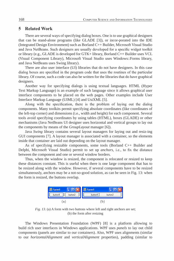
5 Related workThere are several ways of specifying dialog boxes. One is to use graphical designers
that can be stand-alone programs (like GLADE [3]), or incor-porated into the IDE (Integrated Design Environment) such as Borland C++ Builder, Microsoft Visual Studio and Java NetBeans. Such designers are usually developed for a specific widget toolkit or library (e.g., GLADE is developed for GTK+ library, Borland C++ Builder uses VCL (Visual Component Library), Microsoft Visual Studio uses Windows::Forms library, and Java NetBeans uses Swing library).
There are also user interface (UI) libraries that do not have designers. In this case dialog boxes are specified in the program code that uses the routines of the particular library. Of course, such a code can also be written for the libraries that do have graphical designers.
Another way for specifying dialogs is using textual languages. hTML (hyper Text Markup Language) is an example of such language since it allows graphical user interface components to be placed on the web pages. Other examples include User Interface Markup Language (UIML) [4] and UsiXML [5].
Along with the specification, there is the problem of laying out the dialog components. Many toolkits permit specifying absolute coordinates (like coordinates of the left-top corner) and dimensions (i.e., width and height) for each compo nent. Several tools avoid specifying coordinates by using tables (hTML), boxes (GLADE) or other mechanisms (Java NetBeans UI designer uses horizontal and vertical groups to lay out the components by means of the GroupLayout manager [6]).
Java Swing library contains several layout managers for laying out and resiz-ing GUI components [7]. A layout manager is associated with a container, so the elements inside that container are laid out depending on the layout manager.
As of specifying resizable components, some tools (Borland C++ Builder and Delphi, Microsoft Visual Studio) permit to set up anchors, i.e., to fix the distance between the component and one or several window borders.
Thus, when the window is resized, the component is relocated or resized to keep these distances constant. This is useful when there is one large component that has to be resized along with the window. however, if several components have to be resized simultaneously, anchors may be a not-so-good solution, as can be seen in Fig. 13: when the form is resized, the buttons overlap.
Fig. 13. (a) A form with two buttons where left and right anchors are set; (b) the form after resizing
The Windows Presentation Foundation (WPF) [8] is a platform allowing to build rich user interfaces in Windows applications. WPF uses panels to lay out child components (panels are similar to our containers). Also, WPF uses alignments (similar to our horizontalAlignment and verticalAlignment properties), padding (similar to
So, when the window is resized, the component is relocated or resized to keepthese distances constant. This is useful when there is one large component thathas to be resized along with the window. However, if several components haveto be resized simultaneously, anchors may be a not-so-good solution, as can beseen from Fig. 13: when the form is resized, the buttons overlap.
(a) (b)
Fig. 13. (a) A form with two buttons where left and right anchors are set. (b) Theform after resizing.
The Windows Presentation Foundation (WPF) [8] is a platform, which al-lows building rich user interfaces in Windows applications. WPF uses panels tolay out child components (panels are similar to our containers). Also, WPF usesalignments (similar to our horizontalAlignment and verticalAlignment proper-ties), padding (similar to our borders and padding) and margins (similar to ourmargins). The difference is in stretching the components: we use maximal sizesto bound streching, while WPF uses special alignment constant “Stretch”.
An interesting idea for specifying both absolute and relative sizes is basedon usage of linear constraints [9].9 Using the constraints allows to specify thelayout and behaviour of components in a more flexible way. However, definingthe constraints explicitly by means of equations and inequalities is not a naturalway for specifying the properties of UI components. Moreover, the question arisesconcerning what to do if the constraints are unsatisfiable. UI may be generated atruntime, and the components should be laid out despite inconsistent constraints.As was told before, we solve this problem by allowing the maximum sizes to beincreased, when needed.10
Several web-based techniques with very rich capabilities for creating userinterfaces are available for developers today. AJAX is an approach, where severalweb technologies are used to provide fast responses to the user [10]. If the client-side AJAX engine can handle the user request by its own, it does so. Otherwise, arequest (usually, asynchronous) to the server is performed. Google Web Toolkit,GWT [11] is an AJAX-type framework, which provides solutions to many AJAXproblems. With GWT web-based applications are developed in Java. However,at runtime, web-based technologies such as JavaScript and HTML are used.
9 Java also allows for creating layout managers that support constraints.10 A maximum size bound can also be set for the components in order not to allow the
components to become very very large.

169S. Kozlovics. A Dialog Engine Metamodel for the Transformation-Driven Architecture
our borders and padding) and margins (similar to our margins). The difference is in stretching the components: we use maximal sizes to bound streching, while WPF uses special alignment constant "Stretch".
An interesting idea for specifying both absolute and relative sizes is based on the usage of linear constraints [9].9 Using the constraints permits specifying the layout and behaviour of components in a more flexible way. However, defining the constraints explicitly by means of equations and inequalities is not a natural way to specify the properties of UI components. Moreover, the question arises, what to do if the constraints are unsatisfiable. UI may be generated at runtime, and the components should be laid out despite inconsistent constraints. As it was told before, we solve this problem by allowing the maximum sizes to be increased when needed.10
Several web-based techniques with multiple opportunities for creating user interfaces are available for developers today. AJAX is an approach where several web technologies are used to provide fast responses to the user [10]. If the client-side AJAX engine can handle the user request by its own, it does so. Otherwise, a request (usually, asynchronous) to the server is performed. Google Web Toolkit (GWT) [11] is an AJAX-type framework, which provides solutions to many AJAX problems. With GWT, web-based applications are developed in Java. however, at runtime, web-based technologies such as JavaScript and hTML are used.
Microsoft Silverlight [12] and Adobe Flash [13] are two other platforms for providing enhanced user interface experience including interactivity and anima-tions.
The XForms XML format can be used for specifying user interfaces along with data processing on the client's side. XForms is "the next generation of forms technology for the world wide web" [14]. The Apogee project [15] is aimed to provide the XForms engine (and other features) for the Eclipse environment [16].
6 ConclusionThe dialog engine that uses the proposed dialog engine metamodel has been
successfully implemented, although with minor differences, in the graphical tool-building platform GrTP [2] that now uses the principles of the transformation-driven architecture [1]. The implementation of the layout of graphical dialog components is based on the quadratic optimization technique [17].
The GrTP tool contains the universal transformation which allows for common functionality to create graphical modeling tools. Universal transformation can create tool-specific dialog boxes on the fly. However, such generated dialogs do not use all the opportunities the Dialog Engine provides. For example, dialog boxes have the same row-by-row layout. To be able to adjust generated dialog windows, a graphical dialog designer may be added to GrTP.
Acknowledgments. The author would like to thank J. Barzdins and K. Freivalds for valuable personal conversations concerning the topic. Thanks also to A. Sostaks,
9 Java also allows for creating layout managers that support constraints. 10 A maximum size bound can also be set for the components in order not to allow them to become very
large.
170 Computer SCienCe and information teChnologieS
R. Liepins and L. Lace who gave their comments concerning graphical semantics for components. Thanks to others who directly or indirectly helped the author to get the work done.
References1. J. Barzdins, S. Kozlovics, E. Rencis. The Transformation-Driven Architecture. Proceedings of DSM'08
Workshop of OOPSLA 2008. Nashville, USA, 2008, pp. 60–63.2. J. Barzdins et al. GrTP: Transformation-Based Graphical Tool Building Platform. Proceedings of
MODELS 2007. Nashville, Tennessee, USA: MDDAUI, 2007.3. Glade – A User Interface Designer. Available: http://glade.gnome.org.4. M. Abrams, J. helms (Eds.) User Interface Markup Language (UIML) Specification. Working Draft
3.1. 1994. Available: http://www.oasis-open.org/committees/ download.php/5937/uiml-core-3.l-draft-0l-200403ll.pdf. See also: http://www.oasis-open.org/committees/documents.php?wg\abbrev= uiml.
5. UsiXML, USer Interface eXtensible Markup Language. V1.8. February, 2007. Available: http://www.usixml.org/index.php5?mod=download\&file=usixml-doc/UsiXML\_vL8.0-Documentation.pdf.
6. T. Pavek. Get To Know GroupLayout. NetBeans Magazine, No. 1, pp. 58–66. Available: http://www.netbeans.org/download/magazine/01/nb01\group\layout.pdf.
7. Laying Out Components Within a Container. Available: http://java.sun.com/docs/books/tutorial/uiswing/layout/
8. Windows Presentation Foundation. Available: http://msdn.microsoft.com/en-us/library/ms754130.aspx9. C. Lutteroth, G. Weber. User Interface Layout with Ordinal and Linear Con straints. Proceedings of the
7th Australasian User Interface Conference, Vol. 50, pp. 53–60.10. J. J. Garrett. Ajax: A New Approach to Web Applications. Available: AdaptivePath.com, http://www.
adaptivepath.com/ideas/essays/archives/000385.php.11. Google Web Toolkit homepage. Available: http://code.google.com/webtoolkit/.12. The Official Microsoft Silverlight Site. Available: http://www.silverlight.net/.13. Adobe Flash. Available: http://www.adobe.com/products/flash.14. W3C: The Forms Working Group. Available: http://www.w3.org/MarkUp/Forms/.15. The Apogee Project. Available: http://www.eclipse.org/apogee/.16. Eclipse homepage. Available: http://www.eclipse.org.17. K. Freivalds, P. Kikusts. Optimum Layout Adjustment Supporting Ordering Constraints in Graph-Like
Diagram Drawing. Proceedings of the Latvian Academy of Sciences, Section B, Vol. 55, No. 1.