A definition of Fiber Optics - ttu.ee 9.pdfFiber Optical Communication Lecture 9, Slide 2 Fiber...
24
Fiber Optical Communication Lecture 9, Slide 1 Lecture 9 • Multichannel systems – Wavelength division multiplexing • WDM components • Linear crosstalk • Nonlinear crosstalk – Spectral efficiency – Time division multiplexing
Transcript of A definition of Fiber Optics - ttu.ee 9.pdfFiber Optical Communication Lecture 9, Slide 2 Fiber...

Fiber Optical Communication Lecture 9, Slide 1
Lecture 9
• Multichannel systems
– Wavelength division multiplexing
• WDM components
• Linear crosstalk
• Nonlinear crosstalk
– Spectral efficiency
– Time division multiplexing

Fiber Optical Communication Lecture 9, Slide 2
Fiber bandwidth• The bandwidth of fibers is
huge
– Potential bit rate is >> 1 Tbit/s
• In practice, electronics, dispersion, etc. is a bottle neck
– Limits the OOK bit rate to 40 Gbit/s
Simultaneous transmission of many channels offers the simplest way to make better use of the available bandwidth

Fiber Optical Communication Lecture 9, Slide 3
Multichannel approachesFrequency Division Multiplexing (FDM)
• Optical FDM [Wavelength DM (WDM)]
– Multiple optical carriers are modulated with independent bit streams
– The optical data is combined optically into the same fiber
– 100’s of channels can be transmitted this way
• Electrical FDM [subcarrier multiplexing (SCM)]
– Modulating different microwave sub-carriers which are combined to modulate a single optical carrier
Time Division Multiplexing (TDM)
• Optical TDM (OTDM)
– Several signals with identical bit-rate are combined on the same carrier
– Only for RZ formats, not yet commercial
• Electrical TDM (ETDM)
– Channels are combined before modulating a single optical carrier

Fiber Optical Communication Lecture 9, Slide 4
WDM systems (6.1)• WDM system = a single fiber + N transmitters + N receivers + mux/demux
• WDM systems are commercial since 1995
• Spectral efficiency ηs = B/Δνch, today typically ηs < 0.5 (bit/s)/Hz
– Standard D(dense)WDM grid spacing (Δνch) are 200, 100, 50 and 25 GHz
• System limitations include
– Amplifier gain uniformity and laser wavelength stability
– Fiber nonlinearities and other interchannel crosstalk
– Residual dispersion

Fiber Optical Communication Lecture 9, Slide 5
WDM components (6.2)• Implementing a WDM system requires several optical components
– Multiplexers
• Combine the individual WDM channels
– Demultiplexers
• Separate the WDM channels
– Star couplers
• Combine signals from multiple origins and sends to multiple destinations
– Tunable optical filters
• Used to filter out a specific channel
– Wavelength-tunable transmitters
– Add-drop multiplexers/optical routers
• Used in the transmission path to switch channels to correct destinations
• Often the term reconfigurable optical add-drop multiplexer (ROADM) is seen
Fiber Optical Communication Lecture 9, Slide 6
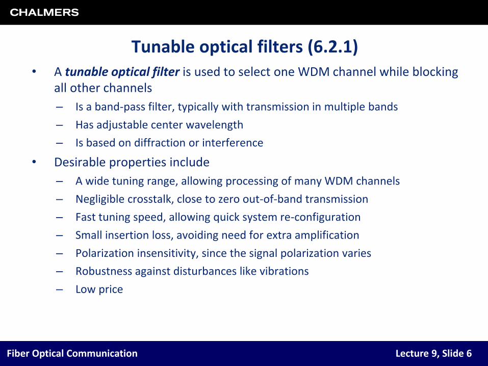
Tunable optical filters (6.2.1)• A tunable optical filter is used to select one WDM channel while blocking
all other channels
– Is a band-pass filter, typically with transmission in multiple bands
– Has adjustable center wavelength
– Is based on diffraction or interference
• Desirable properties include
– A wide tuning range, allowing processing of many WDM channels
– Negligible crosstalk, close to zero out-of-band transmission
– Fast tuning speed, allowing quick system re-configuration
– Small insertion loss, avoiding need for extra amplification
– Polarization insensitivity, since the signal polarization varies
– Robustness against disturbances like vibrations
– Low price

Fiber Optical Communication Lecture 9, Slide 7
Types of tunable optical filters• There are several types of filters
– A Fabry-Perot filter (a) is a cavity between mirrors
• Length is adjustable
• Transmission at longitudinal modes
– A Mach-Zehnder filter (b) is an interferometer
• Uses cascaded Mach-Zehnder interferometers
• Phase shift is wavelength-dependent
– A grating-based Filter (c) uses Bragg gratings
• Reflection is wavelength-dependent
• Often uses an optical circulator
– An acousto-optic filter (d) forms the grating from acoustic waves
• Photoelastic effect ⇒ refractive index is changed
• Set up dynamically

Fiber Optical Communication Lecture 9, Slide 8
The Fabry-Perot filter • Typically, several wavelengths can pass an optical band-pass filter
• The Fabry-Perot filter is a good example
– Transmission of all longitudinal modes of the cavity
– The frequency spacing is known as the free spectral range, given by
• L is cavity length, ng the group index
• Signal bandwidth must be smaller than ΔνL
– The finesse, F, is defined as
• The filter bandwidth is denoted by ΔνFP
• The center wavelength is typically adjusted with a piezoelectric actuator
)2/( Lnc gL
FP/ LF

Fiber Optical Communication Lecture 9, Slide 9
Multiplexers and demultiplexers (6.2.2)• A multiplexer with reversed propagation direction is a demultiplexer
• (De)multiplexing can be done in several different ways
– A grating-based (de)multiplexer is shown in figurein two different implementation alternatives
– A filter-based (de)multiplexer typicallyuses MZ filters
– Fiber Bragg gratings can be used to make a all-fiber (de)multiplexer
– An arrayed waveguide grating (de)multiplexer is seen in lower figure
• Waveguides have different lengths
• Phase shifts are wavelength dependent
• Different channels focus to different outputs
– In a coherent receiver, the channel is selected by tuning the local oscillator frequency
Fiber Optical Communication Lecture 9, Slide 10
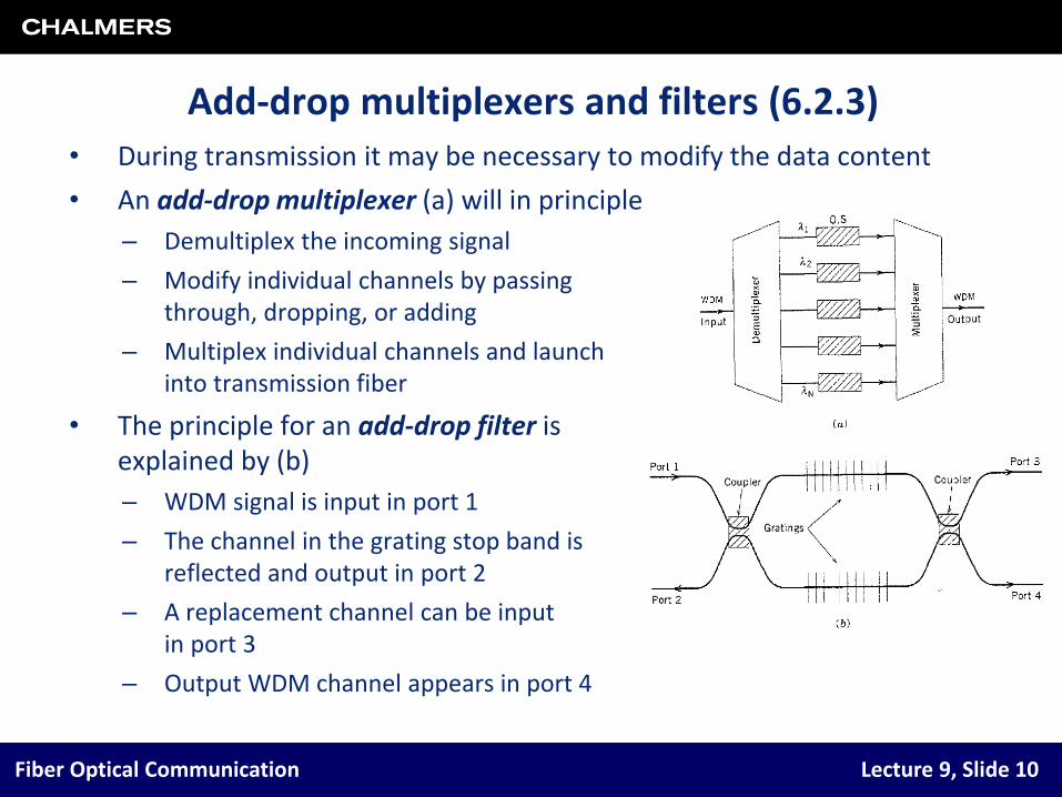
Add-drop multiplexers and filters (6.2.3)• During transmission it may be necessary to modify the data content
• An add-drop multiplexer (a) will in principle
– Demultiplex the incoming signal
– Modify individual channels by passing through, dropping, or adding
– Multiplex individual channels and launchinto transmission fiber
• The principle for an add-drop filter is explained by (b)
– WDM signal is input in port 1
– The channel in the grating stop band is reflected and output in port 2
– A replacement channel can be input in port 3
– Output WDM channel appears in port 4

Fiber Optical Communication Lecture 9, Slide 11
WDM components (6.2.4–6.2.6)• A star-coupler combines input signals and divides among the outputs
– Are not wavelength-selective
– Can be used for broadcasting
• Example: Distribution of television to multiple areas
• A wavelength router will redistribute the channels of multiple incoming WDM signals to multiple output fibers
– Different wavelength ⇒ different receiver
– A common design is the waveguide-grating router (WGR)
• Like a MZI, but with more than 2 arms
• A WDM transmitter can be integrated
– Figure shows a 10 channel system
– OPM = optical power monitor
– EAM = electroabsorption modulators
– VOA = variable optical attenuator

Fiber Optical Communication Lecture 9, Slide 12
Crosstalk in WDM systems
• WDM channels should not interfere with each other during transmission
– The most important design issue is interchannel crosstalk
– Loosely speaking this means power transfer between channels
• Crosstalk occurs due to
– Non-ideal demultiplexing/filtering/routing components (linear crosstalk)
– Nonlinear effects in optical fibers or devices (nonlinear crosstalk)
• Any crosstalk degrades the BER and causes crosstalk-induced penalty
• Linear crosstalk is classified as either out-of-band or in-band crosstalk
– Out-of-band crosstalk means that power ”leaks” from neighboring channels
– In-band crosstalk means that the crosstalk is at the same wavelength
• Occurs in routing/networks
• Adds coherently to the signal

Fiber Optical Communication Lecture 9, Slide 13
Heterowavelength linear crosstalk (6.3.1)• Assume we use
– Direct detection using a photodetector
– An optical bandpass filter for channel selection
• The optical power entering channel m (of a total N) is
– Tmn is the filter transmission of channel n when channel m is selected
• The corresponding photocurrent is
– Ix is the crosstalk contribution
– Ix has different values depending on the data in the interfering channels
– Worst case appears when all interfering channels transmit “one” simultaneously
filter transfer function
N
mn
nmnm PTPP
xch
N
mn
nmnnmm IIPTRPRI
Fiber Optical Communication Lecture 9, Slide 14
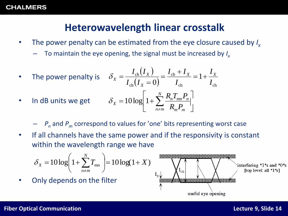
Heterowavelength linear crosstalk• The power penalty can be estimated from the eye closure caused by Ix
– To maintain the eye opening, the signal must be increased by Ix
• The power penalty is
• In dB units we get
– Pn and Pm correspond to values for ’one’ bits representing worst case
• If all channels have the same power and if the responsivity is constant within the wavelength range we have
• Only depends on the filter
chch
ch
ch
ch 10 I
I
I
II
II
II XX
X
XX
N
mn mm
nmnnX
PR
PTR1log10
)1log(101log10 XTN
mn
mnX
Fiber Optical Communication Lecture 9, Slide 15
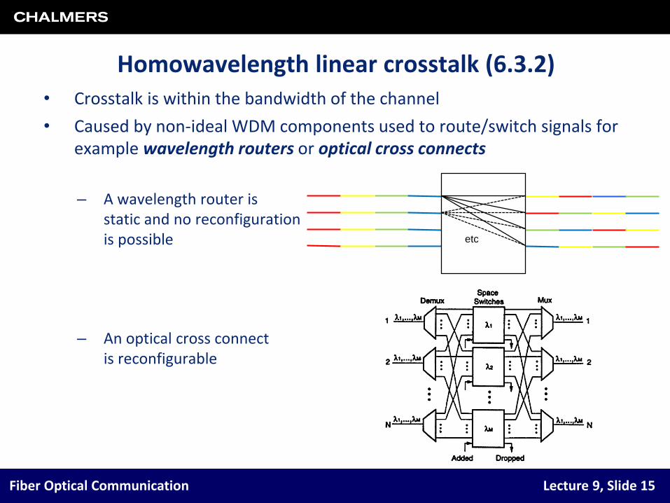
Homowavelength linear crosstalk (6.3.2)• Crosstalk is within the bandwidth of the channel
• Caused by non-ideal WDM components used to route/switch signals for example wavelength routers or optical cross connects
– A wavelength router is static and no reconfigurationis possible
– An optical cross connectis reconfigurable
etc

Fiber Optical Communication Lecture 9, Slide 16
Homowavelength linear crosstalk• In an (N + 1)×(N + 1) router there are N interfering terms (An)
– The field entering the receiver is
• We have signal-crosstalk beating interference
– Compare with ASE beat noise from EDFAs
• All phases are random ⇒ Acts as intensity noise
• The penalty is
– with X = Pn/Pm
)exp()( tiEEtE m
N
mn
nmm
N
mn
nmnmm tttPtPRtRPtI )()(cos)()(2)()(
)1(log10 22
10 QrXX )1(/ 2
0
22 NXPPrX

Fiber Optical Communication Lecture 9, Slide 17
Nonlinear crosstalk (6.3.3–6.3.6)Stimulated Raman scattering (SRS)
• No problem in a single channel system (Pth ≈ 0.5 W)
• In WDM systems SRS acts as a fiber amplifier
– Light at a lower frequency is amplified by the light at a higher frequency
– Depletion of power in the channel at the highest frequency increases with the number of channels
– Max channel power is reduced with increasing number of channels
Stimulated Brillouin scattering (SBS)
• Transfers energy to a field at a lower frequency propagating in the backward direction
• SBS bandwidth is narrow (< 100 MHz)
– Energy transfer is avoided with a channel spacing ≠ SBS frequency downshift (≈ 10 GHz)
– SBS limitation is independent of the number of channels (P < Pth ≈ 10 mW)
Fiber Optical Communication Lecture 9, Slide 18
Nonlinear crosstalkCross-phase modulation (XPM)
• The phase of the signal is changed when co-propagating with other channels
– A linear phase shift is a frequency shift ⇒ timing jitter
• The phase-shift increases linearly with the number of channels
Four-wave mixing (FWM)
• New frequency components are generated from mixing
• The number of generated new frequency components increases with number of channels
• Power in each component is reduced with increasing channel spacing
– Process is phase sensitive

Fiber Optical Communication Lecture 9, Slide 19
Nonlinear crosstalk• Figure shows limitation on
channel power from nonlinear effects
• For few channels, FWM & SBS dominate
• For many channels, XPM & SRS dominate
• Nonlinear crosstalk must be considered in WDM systems, when the launched power per channel is > 0.1–1 mW

Fiber Optical Communication Lecture 9, Slide 20
Spectral efficiency and the capacity• The throughput is the number of successfully transmitted bits/second
– This is often called “capacity” in the fiber-optic world
• Currently, throughput is increased by increasing the spectral efficiency
– Remember: For a WDM system, the spectral efficiency is ηs = B/Δνch
– Done using multi-level modulation formats and polarization multiplexing
– But how large can ηs be? Larger than 1 (bit/s)/Hz?
• The channel capacity is given by Shannon’s famous formula
– Δf is the bandwidth
– C is the capacity
• Provided that the SNR is high, ηs can be >> 1 (bit/s)/Hz
– Example: SNR = 40 dB, Δf = 10 GHz ⇒ C = 133 Gbit/swith Δνch = 50 GHz, ηs = 2.7 (bit/s)/Hz
• Wireless systems can have spectral efficiencies as high as 10 (bit/s)/Hz
– In optical communication this is not easily achieved
)SNR1(log2 fC

Fiber Optical Communication Lecture 9, Slide 21
Spectral efficiency and the capacity• System performance is not completely described by the SNR
• Figure is from Kahn and Ho, IEEE J. Select. Topics Quantum Electron., no. 2, March/April, 2004
– Assuming a coherent receiver
– “Constant-intensity” and “Unconstrained” refer to the modulation format
• PSK has constant intensity (without dispersion)
• Mod. format choice determines the spectralefficiency
• In general, the Shannon capacityof an optical fiber is still an openquestion

Fiber Optical Communication Lecture 9, Slide 22
OTDM channel multiplexing (6.4.1)• OTDM means optical time-division multiplexing
– OTDM is a technique to eliminate the ”electronic bottleneck”
• ”Sub-channels with lower bit rate are interleaved in time
• Enables higher bit rates > 40 Gbit/s
• Total bit rate per channel is B × N
• Can be combined with WDM
• Characteristics:
– Only ”low-speed” electronics required in each “sub-channel”
– Needs RZ format
– Needs precise delay control
– Pulse source requirements:
• Short pulses
• Small timing jitter
• High extinction ratio (> 30 dB)

Fiber Optical Communication Lecture 9, Slide 23
OTDM channel multiplexing (6.4.2)• Several different approaches
– All requires a clock signal at ”sub-channel” bit rate
• Figures show possible implementations:
– Cascaded LiNbO3 modulators
• V0 is required for π phase shift
• Modulators reject other ”sub-channels”
– Nonlinear optical loop mirror
• Normally reflects, based on XPM
• Made transparent by clock signal
– FWM in nonlinear medium
• Often uses highly nonlinear fiber (HNLF)
• Signal is shifted in frequency
• ”Sub-channel” is filtered out

Fiber Optical Communication Lecture 9, Slide 24
Subcarrier multiplexing (6.5)• Subcarrier multiplexing (SCM) = electrical microwave signals encoded
with data are combined to modulate a single optical carrier
– Possible to combine SCM and WDM
– Figure shows 4 WDM channels, each with 5 SCM channels
• The modulation can be analog or digital (or a combination)
– Analog format is often used for video distribution