A Defense Security Approach against Hacking Using Trusted Graphs
6
International Journal of Science and Research (IJSR) ISSN (Online): 2319-7064 Impact Factor (2012): 3.358 Volume 3 Issue 8, August 2014 www.ijsr.net Licensed Under Creative Commons Attribution CC BY A Defense Security Approach against Hacking Using Trusted Graphs D. N. Rewadkar 1 , Harshal A. Kute 2 1 Head, Department of Computer Engineering, RMD Sinhgad School of Engineering, University of Pune, India 2 Department of Computer Engineering, RMD Sinhgad School of Engineering, University of Pune, India Abstract: Nowadays, accessing information and exchanging of data in business industry is increasing. But it also increases the risk of Security. One of important security problem is ‘Hacking’. Hacking is the practice of modifying the features of system, in order to accomplish a goal outside of the creator’s original purpose. Number of solutions is provided against hacking but they are unable to address those issues. This paper explains the dynamic security approach for entire infrastructure to protect against hacking. The proposed infrastructure avoids the three pre-hacking steps. It generates the trusted graph and creates the confusion in front of hacker. Hacker cannot understand the current communication infrastructure and it is difficult for him to break the system easily. Keywords: Component, trusted graph, hacking, network security, understanding agent. 1. Introduction The state of the security on internet is bad and becomes worse. The explosive growth of internet has brought many good things, but there is also a dark side: Criminal hacker. The initial design for common communication protocols indicates that the technology was proposed to meet main requirements such as speed, performance, efficiency and reliability but security was not a concern at that stage [1]. Hacking is descriptive term used to describe the attitude and behavior of group of people who are greatly involved in technical activity which results in gaining unauthorized access. Hacking on computer systems might lead to loss of money, leak of sensitive information and loss of reputation [2]. This proposed security approach is designed to eliminate the possibility of hacking by targeting the three pre-hacking steps: foot printing, scanning and enumeration at network level. These are the basic three steps of hacking which gives detailed understanding about the targeted infrastructure. This paper aim to design a dynamic security approach that is mainly directed to defend hacking. 2. Background Hacking means gaining an unauthorized access to computer and network resources with malicious intent. People who hack computers are known as hackers. Hackers break into computer systems by exploiting security vulnerabilities, such as poor configuration of web servers, disabled security controls or poorly chosen passwords. 2.1 The behavior of hackers Figure 1: Behavior of hackers 2.1.1 Footprinting It is a crafted technique in gathering information. A hacker at this stage is trying to understand how a potential victim operates. It is related to narrowing down the target of interest and investigating every entity related to the target. At this step, the hacker obtains a unique profile about their target [1]. 2.1.2 Scanning Unique profile lists out enough information about the victim such as list of IP addresses and network blocks. From that point, the hacker starts sending packets to their victim’s system look for some the point of entry [1]. 2.1.3 Enumeration At the final stage, the hacker has effectively recognized points of entry. Enumeration is a process which includes Paper ID: 02015842 1879
Transcript of A Defense Security Approach against Hacking Using Trusted Graphs

International Journal of Science and Research (IJSR) ISSN (Online): 2319-7064
Impact Factor (2012): 3.358
Volume 3 Issue 8, August 2014 www.ijsr.net
Licensed Under Creative Commons Attribution CC BY
A Defense Security Approach against Hacking Using Trusted Graphs
D. N. Rewadkar1, Harshal A. Kute2
1Head, Department of Computer Engineering, RMD Sinhgad School of Engineering, University of Pune, India
2Department of Computer Engineering, RMD Sinhgad School of Engineering, University of Pune, India Abstract: Nowadays, accessing information and exchanging of data in business industry is increasing. But it also increases the risk of Security. One of important security problem is ‘Hacking’. Hacking is the practice of modifying the features of system, in order to accomplish a goal outside of the creator’s original purpose. Number of solutions is provided against hacking but they are unable to address those issues. This paper explains the dynamic security approach for entire infrastructure to protect against hacking. The proposed infrastructure avoids the three pre-hacking steps. It generates the trusted graph and creates the confusion in front of hacker. Hacker cannot understand the current communication infrastructure and it is difficult for him to break the system easily. Keywords: Component, trusted graph, hacking, network security, understanding agent. 1. Introduction The state of the security on internet is bad and becomes worse. The explosive growth of internet has brought many good things, but there is also a dark side: Criminal hacker. The initial design for common communication protocols indicates that the technology was proposed to meet main requirements such as speed, performance, efficiency and reliability but security was not a concern at that stage [1]. Hacking is descriptive term used to describe the attitude and behavior of group of people who are greatly involved in technical activity which results in gaining unauthorized access. Hacking on computer systems might lead to loss of money, leak of sensitive information and loss of reputation [2]. This proposed security approach is designed to eliminate the possibility of hacking by targeting the three pre-hacking steps: foot printing, scanning and enumeration at network level. These are the basic three steps of hacking which gives detailed understanding about the targeted infrastructure. This paper aim to design a dynamic security approach that is mainly directed to defend hacking. 2. Background Hacking means gaining an unauthorized access to computer and network resources with malicious intent. People who hack computers are known as hackers. Hackers break into computer systems by exploiting security vulnerabilities, such as poor configuration of web servers, disabled security controls or poorly chosen passwords.
2.1 The behavior of hackers
Figure 1: Behavior of hackers
2.1.1 Footprinting It is a crafted technique in gathering information. A hacker at this stage is trying to understand how a potential victim operates. It is related to narrowing down the target of interest and investigating every entity related to the target. At this step, the hacker obtains a unique profile about their target [1]. 2.1.2 Scanning Unique profile lists out enough information about the victim such as list of IP addresses and network blocks. From that point, the hacker starts sending packets to their victim’s system look for some the point of entry [1]. 2.1.3 Enumeration At the final stage, the hacker has effectively recognized points of entry. Enumeration is a process which includes
Paper ID: 02015842 1879

International Journal of Science and Research (IJSR) ISSN (Online): 2319-7064
Impact Factor (2012): 3.358
Volume 3 Issue 8, August 2014 www.ijsr.net
Licensed Under Creative Commons Attribution CC BY
active engagement and direct queries with the target’s systems [1]. 3. Related Security Approaches There are number of security solutions, it is either a passive defense or active defense approach. Passive defense systems such as Firewalls, Intrusion Detection Systems (IDS) are security approaches, in which there are still limitations present in each of these systems. However, Active defense systems such as Intrusion Detection and Prevention (IDP), and Honeypots, are considered more advanced security approaches that detect common and some new intrusions and actively respond to these attacks. 3.1 Firewalls Firewalls are crucial elements in network security and it has function of a firewall is to examine each incoming and outgoing packet and decide whether to accept or to discard the packet based on its policy [3]. Depending on the technical capability of firewall designers, errors might be introduced if a firewall designer is not highly trained and experienced [3]. Due to the lack of tools for analyzing firewall policies, most firewalls on the Internet have been plagued with policy errors. A firewall policy error either creates security holes that will allow malicious traffic to sneak into a private network or blocks legitimate traffic and disrupts normal business processes, which in turn could lead to irreparable, if not tragic, consequences [3]. 3.2 Intrusion detection systems (IDS) An intrusion detection system (IDS) is a system used to detect unauthorized intrusions into computer systems and networks. Basically, it has been designed and proposed under the assumption that a normal user’s behavior is completely different than an intruder. IDS have the ability to analyze, detect intrusion, recognize the source of attack and alleviate the effect of most of unexplored attacks [4]. There are some drawbacks related to that technology. Anomaly Intrusion Detection system has large number of false positive alerts. Furthermore, the dynamic feature which is supposed to detect new forms of attacks is very difficult in reality. 3.3 Intrusion Detection and Prevention System (IDP) IDP shares the same characteristics with IDS but instead of generating alerts, IDP performs actions against the intrusion [5]. As well as it inherits all drawbacks of IDS. 3.4 Honeypot The Honeynet provides a new method by luring hackers to a system and then analyzing their activities from the start. This approach effectively complements other well-known intrusion detection and prevention technologies [6]. The fundamental concept of designing Honeypot is to study hackers behaviors and assist the efforts made against hackers
besides firewalls, IDSs and IDPs. One use of honeypot system is for deception; the deception is mainly targeted hackers, luring them to valueless network for their activities to be observed and recorded and these resources must appear realistic [6]. Most of honeypot is set to work in one segment making it very easy for hackers to detect them. Actually, the benefit gained from these traps is none. Hackers notice these traps and avoid presenting their tools and methodologies for breaching which leaves honeypot useless [1]. 4. Proposed system The given security approach creates a confusion of the communication within the intended infrastructure and provide a meaninglessness of the communication; thus, hard to be investigated and breached. It facilitates communication within the infrastructure in a most confused method. In this approach, the hacker cannot understand the communication logic and obtain nothing even if they eavesdropped in the communication between all nodes, it is impossible for them to form hacking strategies and thus nearly impossible to perform any task. 4.1 The Approach Design The given approach consists of four main parts: Trusted Graph, Dynamic Protocol Decoder, Monitor Engine and Understanding Agents. 4.1.1 Trusted Graphs It is a definition of the logic communication sequences within all endpoints inside the infrastructure. It is a behavior of a trusted user. The trusted graph forces all endpoints within the infrastructure to follow a sequence of communication which facilitates obfuscation and meaninglessness of the communication [1]. The illusion of randomization concept is applied in the communication sequence between all nodes inside the infrastructure. That concept creates confusion since all nodes communicate with each other in a formal connection definition and continually changes. For generating the trusted graph, it uses any randomized algorithm. Trust network: A trust network can be formed based on transitive trust, with each link representing the trust relationships between two participants. Trusted graph: A trusted graph is a sub-network of a trust network and connected by a set of trusted paths.
Paper ID: 02015842 1880

International Journal of Science and Research (IJSR) ISSN (Online): 2319-7064
Impact Factor (2012): 3.358
Volume 3 Issue 8, August 2014 www.ijsr.net
Licensed Under Creative Commons Attribution CC BY
Figure 2: Trusted Graph
There are three key steps, namely, preprocessing a social network (PSN), building a trust network (BTN), and generating a trusted graph (GTG) [7].
Figure 3: Framework
A. PSN Process 1. Divide the neighbors of user i into three categories by their social distance from i, and one neighbor can be in only one category. Category 1: local neighbors. Category 2: longer contact. Category 3: longest contact. In each Category, sort the neighbors with their priority in descending order. 2. Select next hop neighbors uniformly from the three categories in this way: Firstly, choose the one with the highest priority in Category 3; then, choose the one with the highest priority in Category 2; finally, choose the one with the highest priority in Category 1. If it is necessary to choose more nodes, do the same process iteratively with the remaining nodes.
Figure 4: The three categories of local neighbors, longer,
and longest contacts and Selection of next neighbors. B. BTN: Building the Trust Network To build a trust network from SOURCE to SINK, two things need to be done: 1. Find as many short paths for the two given nodes as
possible, which is a typical breadth-first search. 2. Add trust information between directly connected nodes. We use the breadth-first search in BTN process: Let G be the social network after the PSN process, let L be the max length of paths, and let c be used to control the path length. Let L+(u) denote the set of trusted acquaintances of u, which are selected by the PSN process and are sorted in descending order by their priorities in each category of longest contacts, longer contacts, and local neighbors. Let Rsource denote the unvisited nodes. Algorithm 1: CBFS (G, SOURCE, SINK) 1: Input: G. SOURCE, a trustor; SINK, a trustee. 2: Output: D, a path set from SOURCE to SINK. 3: c ← L − 1. Let SOURCE be the current node. 4: for each neighbor u in Rsource of current node do 5: if u is SINK then 6: do backtracking to get a path P, add P into D. 7: Continue to next loop. 8: else 9: if c > 0 then 10: Add all nodes in L+(u) into Rsource. c ← c − 1. 11: Set u as visited. 12: end if 13: end if 14: end for Algorithm 1 is executed in a centralized server, where the network information is stored. Therefore, the server will have to provide both storage and computation. If many users are requesting trust evaluations of someone else, the server will be very busy.
Paper ID: 02015842 1881

International Journal of Science and Research (IJSR) ISSN (Online): 2319-7064
Impact Factor (2012): 3.358
Volume 3 Issue 8, August 2014 www.ijsr.net
Licensed Under Creative Commons Attribution CC BY
Figure 5:.An example of the BSN and GTG process
Consider above example. After running CBFS or DBFS on Fig.5 (a), we will get paths: SOURCE-1-SINK, SOURCE-2-6-9-SINK, SOURCE-3-7-SINK, SOURCE-4-SINK. The edge e(3, 8) and node 8 are excluded because they cannot reach SINK. The path SOURCE- 2-5-9-SINK is also deleted because when node 5 is being visited, its neighbor 9 has been visited by 6 (who has a higher priority than 5, since p(2, 6) = 0.8 and p(2, 5) = 0.7), and there is no other neighbor available for 5 to reach the sink. C. GTG: Generating the Trusted Graph The goal of the GTG process is to select short, trusted paths from the trust network. Algorithm 2: GTG (D, SOURCE, SINK) 1: Input: D. SOURCE, SINK. 2: Output: Set D�, a trusted path set from SOURCE to SINK. 3: for each path P in D do 4: Delete P if the length of P is bigger than L. 5: Delete P if any RT(i, j) of P is lower than trust threshold. 6: end for GTG (Algorithm 2) can be used to generate the trusted graph. Let D represent the resulting path set from the BTN process, let RT(i, j) represent the referral trust from node i to node j, and let e(i, j) be an edge of a path. Referral trust - referral trust from i to j is equal to the priority of j to be selected as the next hop. Take Fig 5(b) as an example. Suppose that we get the trust values as labeled on the edges in Fig 5 (b), and the trust threshold th = 0.5. After the GTG process, the path SOURCE-1-SINK will be excluded, since the trust value from SOURCE to node 1 is lower than th. Up until now, the trusted graph from SOURCE to SINK is generated.
Trusted Graphs Example: The example of the trusted graph illustrates the virtual connection between all nodes. In order for an endpoint, this holds an IP address (192.186.1.112), to require communication with a host (192.186.1.114). The trusted graph in that example (see figure) shows that the host (192.186.1.112) is directly connected to two hosts (192.186.1.200) and (192.186.1.150) which means that the original host cannot communicate directly with its intended destination (192.186.1.114). Instead, it has two options: 1) Send the packet to 192.186.1.150 and the host (192.186.1.150) will send that packet to (192.186.1.200) and afterwards to 192.186.1.114. 2) A direct connection to 192.186.1.114 via host (192.186.1.200). In designing this approach, we are fully aware of hackers’ abilities to investigate the system and generate a cracking method for it. Thus, the approach contains a dynamic feature that updates the trusted graph architecture in a period of time which is not enough for hackers to understand the current architecture of the trusted graph.
Figure 6: Communication Sequence in trusted graph
Paper ID: 02015842 1882
International Journal of Science and Research (IJSR) ISSN (Online): 2319-7064
Impact Factor (2012): 3.358
Volume 3 Issue 8, August 2014 www.ijsr.net
Licensed Under Creative Commons Attribution CC BY
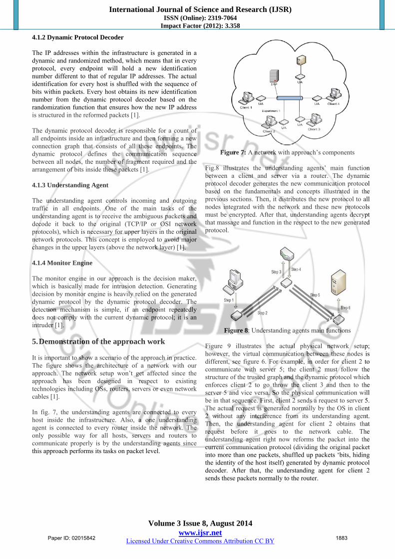
4.1.2 Dynamic Protocol Decoder The IP addresses within the infrastructure is generated in a dynamic and randomized method, which means that in every protocol, every endpoint will hold a new identification number different to that of regular IP addresses. The actual identification for every host is shuffled with the sequence of bits within packets. Every host obtains its new identification number from the dynamic protocol decoder based on the randomization function that ensures how the new IP address is structured in the reformed packets [1]. The dynamic protocol decoder is responsible for a count of all endpoints inside an infrastructure and then forming a new connection graph that consists of all these endpoints. The dynamic protocol defines the communication sequence between all nodes, the number of fragment required and the arrangement of bits inside these packets [1]. 4.1.3 Understanding Agent The understanding agent controls incoming and outgoing traffic in all endpoints. One of the main tasks of the understanding agent is to receive the ambiguous packets and decode it back to the original (TCP/IP or OSI network protocols), which is necessary for upper layers in the original network protocols. This concept is employed to avoid major changes in the upper layers (above the network layer) [1]. 4.1.4 Monitor Engine The monitor engine in our approach is the decision maker, which is basically made for intrusion detection. Generating decision by monitor engine is heavily relied on the generated dynamic protocol by the dynamic protocol decoder. The detection mechanism is simple, if an endpoint repeatedly does not comply with the current dynamic protocol; it is an intruder [1]. 5. Demonstration of the approach work It is important to show a scenario of the approach in practice. The figure shows the architecture of a network with our approach. The network setup won’t get affected since the approach has been designed in respect to existing technologies including OSs, routers, servers or even network cables [1]. In fig. 7, the understanding agents are connected to every host inside the infrastructure. Also, a one understanding agent is connected to every router inside the network. The only possible way for all hosts, servers and routers to communicate properly is by the understanding agents since this approach performs its tasks on packet level.
Figure 7: A network with approach’s components
Fig.8 illustrates the understanding agents’ main function between a client and server via a router. The dynamic protocol decoder generates the new communication protocol based on the fundamentals and concepts illustrated in the previous sections. Then, it distributes the new protocol to all nodes integrated with the network and these new protocols must be encrypted. After that, understanding agents decrypt that massage and function in the respect to the new generated protocol.
Figure 8: Understanding agents main functions
Figure 9 illustrates the actual physical network setup; however, the virtual communication between these nodes is different, see figure 6. For example, in order for client 2 to communicate with server 5; the client 2 must follow the structure of the trusted graph and the dynamic protocol which enforces client 2 to go throw the client 3 and then to the server 5 and vice versa. So the physical communication will be in that sequence. First, client 2 sends a request to server 5. The actual request is generated normally by the OS in client 2 without any interference from its understanding agent. Then, the understanding agent for client 2 obtains that request before it goes to the network cable. The understanding agent right now reforms the packet into the current communication protocol (dividing the original packet into more than one packets, shuffled up packets ‘bits, hiding the identity of the host itself) generated by dynamic protocol decoder. After that, the understanding agent for client 2 sends these packets normally to the router.
Paper ID: 02015842 1883
International Journal of Science and Research (IJSR) ISSN (Online): 2319-7064
Impact Factor (2012): 3.358
Volume 3 Issue 8, August 2014 www.ijsr.net
Licensed Under Creative Commons Attribution CC BY
Figure 9: Connection
The understanding agent for the router receives these packets and based on the trusted graph the understanding agent for the router resends these packets to client 3 with little bit of confusion. If the understanding agent for the router redirects messages directly to the next node in the graph, hackers can easily identify the architecture of the trusted graph. So, the understanding agent for the router sends these packets to its destination with extra packets to some nodes for confusion purpose. Subsequently, the understanding agents for client 3 receives the divided packets originally sent by client 2 and recognizes that theses packets are directed to server 5; so, the understanding agent for the client 3 resends these packets to the router again. The same step illustrated before when the understanding agents for the router receives the packets from client 2, is performed again by the router’s understanding agent but the packets are directed to its destination (server 5) with the same confusion concept. Now the understanding agent for server 5 receives these packets and from their formation, the understanding agent reforms these packets into its original form (exactly like what client 2 generates before but it has been modified by the understanding agent for client 2). After reforming it again, server 5 receives this request and replies to it normally. These communication steps are performed again for the reply generated by server 5 to its final destination client 2. Hence, this approach provides a complex communication infrastructure [1]. 6. Conclusion The proposed system is to develop a conceptual dynamic security approach against hacking in general. This approach is also constructed to target the three essential pre-hacking steps, which results on launching an attack against infrastructures practically complicated. It facilitates communication within the infrastructure in a most confused method. Therefore, it is impossible for hacker to form hacking strategies because of confusion and thus nearly impossible to perform any task. This approach is a new security solution compared with its own kind.
References [1] Saad Alsunbul, Phu Le,Jefferson Tan “A defense
security approach for infrastructures against hacking”, 2013 IEEE DOI 10.1109/TrustCom.2013.197, pp.1600-1606.
[2] B. Smith, Yurcik, W., Doss, D., "Ethical hacking: the security justification redux," in Technology and Society, 2002. (ISTAS'02). 2002 International Symposium on, 2002, pp. 374-379.
[3] A. X. Liu and M. G. Gouda, "Firewall Policy Queries," Parallel and Distributed Systems, IEEE Transactions on, vol. 20, pp. 766-777, 2009.
[4] B. Mukherjee, L. T. Heberlein, and K. N. Levitt, "Network intrusion detection," Network, IEEE, vol. 8, pp. 26-41, 1994.
[5] M. Sourour, B. Adel, and A. Tarek, "Environmental awareness intrusion detection and prevention system toward reducing false positives and false negatives," in Computational Intelligence in Cyber Security, 2009. CICS '09. IEEE Symposium on, 2009, pp. 107-114.
[6] L. Spitzner, "The Honeynet Project: trapping the hackers," Security & Privacy, IEEE, vol. 1, pp. 15-23, 2003.
[7] Wenjun Jiang, Guojun Wang, Jie Wu, “Generating trusted graphs for trust evaluation in online social networks”, 2012 Elsevier, doi:10.1016/j.future.2012.06.010.
Author Profile
Prof. D. N. Rewadkar Prof. D. N. Rewadkar received M.E. Computer Technology, from S.R.T.M. University, Nanded. (2000). Currently he is working as an Associate Professor & Head the Department of Computer Engineering, in RMD Sinhgad Technical
Institutes Campus, Warje, Pune. He was a Member of Board of Study (BOS) committee of S.R.T. Marathwada University, Nanded for Computer Science & Engineering. His area of interest is Traffic Engineering & Mobile Communication. He has 21 years of teaching experience.
Harshal A. Kute Reseach Scholar RMD Sinhgad School of Engineering, University of Pune. He has received B.E. in Information Technology from Information Technology department of Sinhgad College of Engineering from University of Pune, Pune
(2013). Currently he is pursuing M.E. in Computer Engineering from RMD Sinhgad School of Engineering, Warje, Pune, University of Pune.
Paper ID: 02015842 1884


![[TROOPERS17]What happened to your home(IoT … · Name:MoonbeomPark I’m a deputy general researcher in TTPA(Trusted Third PartyAgency)ofKorea,has10yearsofexperiencein hacking analysis,](https://static.fdocuments.net/doc/165x107/5b5e980f7f8b9a6d448c8dc8/troopers17what-happened-to-your-homeiot-namemoonbeompark-im-a-deputy.jpg)