
A Cyber Expert System for Auto-Tuning Powered Prosthesis ...
12
A Cyber Expert System for Auto-Tuning Powered Prosthesis Impedance Control Parameters HE HUANG, 1,2 DUSTIN L. CROUCH, 1,2 MING LIU, 1,2 GREGORY S. SAWICKI, 1,2 and DING WANG 1,2 1 UNC/NCSU Joint Department of Biomedical Engineering, North Carolina State University, 4402D Engineering Building III, Raleigh, NC 27695, USA; and 2 UNC/NCSU Joint Department of Biomedical Engineering, University of North Carolina at Chapel Hill, 150A MacNider Hall, Chapel Hill, NC 27599, USA (Received 25 March 2015; accepted 15 September 2015) Associate Editor Dan Elson oversaw the review of this article. Abstract—Typically impedance control parameters (e.g., stiffness and damping) in powered lower limb prostheses are fine-tuned by human experts (HMEs), which is time and resource intensive. Automated tuning procedures would make powered prostheses more practical for clinical use. In this study, we developed a novel cyber expert system (CES) that encoded HME tuning decisions as computer rules to auto-tune control parameters for a powered knee (passive ankle) prosthesis. The tuning performance of CES was preliminarily quantified on two able-bodied subjects and two transfemoral amputees. After CES and HME tuning, we observed normative prosthetic knee kinematics and improved or slightly improved gait symmetry and step width within each subject. Compared to HME, the CES tuning procedure required less time and no human intervention. Hence, using CES for auto-tuning prosthesis control was a sound concept, promising to enhance the practical value of powered prosthetic legs. However, the tuning goals of CES might not fully capture those of the HME. This was because we observed that HME tuning reduced trunk sway, while CES sometimes led to slightly increased trunk motion. Additional research is still needed to identify more appropriate tuning objectives for powered prosthetic legs to improve amputees’ walking function. Keywords—Powered prosthetic legs, Biomechanics, Gait, Expert system, Calibration, Transfemoral amputation. LIST OF SYMBOLS k Stiffness h E Equilibrium position C Damping coefficient h p Prosthesis knee joint angle _ h p Prosthesis knee joint angular velocity h peak Peak knee angle T dura Gait phase duration _ h peak Peak angular velocity m Membership function value D Rule degree N Negative P Positive CES Cyber expert system HME Human expert CV Coefficient of variation DF Statistical degrees of freedom GRF Ground reaction force IC Impedance control IDS Initial double support PKP Powered knee prosthesis RMS Root-mean-square SI Symmetry index SS Single support SWE Swing extension SWF Swing flexion TDS Terminal double support INTRODUCTION Over 600,000 people in the US live with major lower limb loss, and the prevalence of limb amputation is expected to double by 2050. 4,46 Many amputees rely on lower limb prostheses to regain some function of the missing limb, though their mobility, stability, and community participation remain substantially lim- ited. 23 Compared to traditional energetically-passive devices, modern powered knee prostheses promise to restore more natural locomotion and provide greater functionality. 2,15,20,37,39 Most powered knee prostheses Address correspondence to He Huang, UNC/NCSU Joint Department of Biomedical Engineering, North Carolina State University, 4402D Engineering Building III, Raleigh, NC 27695, USA. Electronic mails: [email protected] and [email protected] Annals of Biomedical Engineering (Ó 2015) DOI: 10.1007/s10439-015-1464-7 Ó 2015 Biomedical Engineering Society
Transcript of A Cyber Expert System for Auto-Tuning Powered Prosthesis ...
A Cyber Expert System for Auto-Tuning Powered Prosthesis Impedance
Control Parameters
HE HUANG,1,2 DUSTIN L. CROUCH,1,2 MING LIU,1,2 GREGORY S. SAWICKI,1,2 and DING WANG1,2
1UNC/NCSU Joint Department of Biomedical Engineering, North Carolina State University, 4402D Engineering Building III,Raleigh, NC 27695, USA; and 2UNC/NCSU Joint Department of Biomedical Engineering, University of North Carolina at
Chapel Hill, 150A MacNider Hall, Chapel Hill, NC 27599, USA
(Received 25 March 2015; accepted 15 September 2015)
Associate Editor Dan Elson oversaw the review of this article.
Abstract—Typically impedance control parameters (e.g.,stiffness and damping) in powered lower limb prostheses arefine-tuned by human experts (HMEs), which is time andresource intensive. Automated tuning procedures would makepowered prosthesesmore practical for clinical use. In this study,we developed a novel cyber expert system (CES) that encodedHME tuning decisions as computer rules to auto-tune controlparameters for a powered knee (passive ankle) prosthesis. Thetuning performance ofCESwas preliminarily quantified on twoable-bodied subjects and two transfemoral amputees. AfterCES and HME tuning, we observed normative prosthetic kneekinematics and improved or slightly improved gait symmetryand step width within each subject. Compared to HME, theCES tuning procedure required less time and no humanintervention. Hence, using CES for auto-tuning prosthesiscontrolwas a sound concept, promising to enhance the practicalvalue of powered prosthetic legs. However, the tuning goals ofCES might not fully capture those of the HME. This wasbecause we observed that HME tuning reduced trunk sway,while CES sometimes led to slightly increased trunk motion.Additional research is still needed to identify more appropriatetuning objectives for powered prosthetic legs to improveamputees’ walking function.
Keywords—Powered prosthetic legs, Biomechanics, Gait,
Expert system, Calibration, Transfemoral amputation.
LIST OF SYMBOLS
k StiffnesshE Equilibrium positionC Damping coefficienthp Prosthesis knee joint angle
_hp Prosthesis knee joint angular velocityhpeak Peak knee angleTdura Gait phase duration_hpeak Peak angular velocitym Membership function valueD Rule degreeN NegativeP PositiveCES Cyber expert systemHME Human expertCV Coefficient of variationDF Statistical degrees of freedomGRF Ground reaction forceIC Impedance controlIDS Initial double supportPKP Powered knee prosthesisRMS Root-mean-squareSI Symmetry indexSS Single supportSWE Swing extensionSWF Swing flexionTDS Terminal double support
INTRODUCTION
Over 600,000 people in the US live with major lowerlimb loss, and the prevalence of limb amputation isexpected to double by 2050.4,46 Many amputees rely onlower limb prostheses to regain some function of themissing limb, though their mobility, stability, andcommunity participation remain substantially lim-ited.23 Compared to traditional energetically-passivedevices, modern powered knee prostheses promise torestore more natural locomotion and provide greaterfunctionality.2,15,20,37,39 Most powered knee prostheses
Address correspondence to He Huang, UNC/NCSU Joint
Department of Biomedical Engineering, North Carolina State
University, 4402D Engineering Building III, Raleigh, NC 27695, USA.
Electronic mails: [email protected] and [email protected]
Annals of Biomedical Engineering (� 2015)
DOI: 10.1007/s10439-015-1464-7
� 2015 Biomedical Engineering Society

rely on finite state impedance control (IC), which ad-justs the impedance of the knee joints based on gaitphase.19,37 The desired IC parameter values in eachgait phase are often fine-tuned manually and heuristi-cally by a prosthetist, based on observations of thepatient’s gait performance and feedback, until theamputee’s gait ‘‘looks good’’.37 Manual tuning pre-sents a serious clinical challenge since it lacks precision,is time and resource intensive, and must be conducteduniquely for each amputee to account for between-patient variation. New approaches that can config-ure the prosthesis control parameters quickly and cost-effectively are needed to make powered lower limbprostheses more practical for clinical use.
The two main concepts to simplify the tuning pro-cedure have been (1) to mimic able-bodied or soundlimb impedance at prosthetic joints, and (2) to reducethe number of parameters that need to be tuned. Bio-logical joint impedances have been computed directlyfrom experimental measurements and estimated usingbiomechanical models.14,24,31–34,42,43 Due to experi-mental limitations, in vivo joint impedance duringambulation has only been measured at the ankle dur-ing the stance portion of gait.31 Impedance measure-ments at other joints, such as the knee, were madeunder static or quasi-static conditions and thereforemay not transfer to dynamic ambulationtasks.14,24,42,43 Impedance estimated from muscu-loskeletal biomechanical models has only been vali-dated for the stance phase of gait.29,30 Given thelimited availability of biological impedance data,applying it toward the control of prosthetic jointsduring ambulation has not yet been demonstrated.
In a finite state machine-based controller, reducingthe number of control parameters that must be cali-brated may be achieved by defining fewer states.7,11,17
However, only modest simplification can be achievedsince at least 3 states are typically defined for level-ground walking, and parameter values differ acrosstasks (i.e., ramp ascent/descent, stair ascent/des-cent).16,18,38 Another solution to tune fewer parametersis to associate parameter values with one another36 orwith other intrinsic biomechanical measures (e.g.,prosthesis joint angles, prosthesis load, walking speed,foot center of pressure, effective leg shape).8,10,36 Inone case, this strategy not only reduced the burden ofmanual tuning, but also permitted alternate nonlinearcontrol systems that had fewer control parametersaltogether.8 However, given their complexity, explicitrelationships between biomechanical measures andcontrol parameters may be imprecisely known andpotentially unsuitable as a basis for prosthesis control.Ultimately, parameter reduction only simplifies thetuning procedure, leaving many of the practical costsand challenges of tuning powered prostheses unsolved.
Fundamentally different from existing approaches,our new concept is to configure the impedance controlparameters for powered prostheses using a cyber ex-pert system (CES). A branch of artificial intelligence,CESs encode human expert (HME) factual knowledgeor skills into a computer system as databases andrules.35 HME knowledge can be represented in severalways, including a semantic network, production rules,predicate logic, object-attribute-value, hybrids, andscripts, depending on the type of knowledge and fieldof application.1 In our application, HMEs tune pros-thesis control parameters by qualitatively observingknee kinematics and gait characteristics (e.g., stridelength and step symmetry), which involve cause-and-effect decisions that are typically represented as pro-duction rules. Additionally, since tuning decisions varydepending on the magnitude of observed, continuouslyvarying gait characteristics, HME knowledge is bestrepresented in a sliding scale manner using fuzzy logic,rather than traditional crisp logic.25
Motivated by this new CES tuning concept, in thisstudy we aimed to develop a rule-based CES to auto-matically tune the impedance control parameters for apowered knee (passive ankle) prosthesis. The CESperformance was quantified on four human subjects toshow the feasibility of our novel design. The developedcyber-expert system and study results may lead to apractical solution to configure powered prosthesis im-pedance control parameters quickly, accurately, andcost-effectively—all features that should facilitate thewidespread adoption of advanced powered kneeprostheses.
MATERIALS AND METHODS
Prosthesis Design and Control Structure
We used a powered knee prosthesis (PKP) proto-type previously developed by our research group.18
The knee joint, comprised of a moment arm and pylon,was driven by a direct current motor (Maxon,Switzerland) through a ball screw (THK, Japan).Sensors were embedded in the PKP to measure kneejoint angle (potentiometer), knee joint angular velocity(encoder connected with the motor), and groundreaction force (GRF) (6 degrees of freedom load cell(ATI, NC, USA) mounted in line with the shank py-lon). The powered prosthesis was tethered and con-trolled by a desktop PC. A multi-functional dataacquisition card (National Instruments, TX, USA)collected all sensor measurements at 100 Hz and pro-vided digital-to-analog control output to drive the DCmotor through a motor controller (Maxon, Switzer-land). A low profile prosthetic foot (1E57 Lo Rider,Otto Bock, Germany) was used in the prototype.
HUANG et al.
Finite-state impedance control (IC) was used tocontrol knee forces generated by the PKP during gait.The level ground walking gait cycle was divided intofive states (phases): initial double support (IDS), singlesupport (SS), terminal double support (TDS), swingflexion (SWF), and swing extension (SWE).28 Transi-tions between states were triggered by the GRF, kneejoint angle, and knee joint angular velocity measuredfrom the prosthesis.19 Within each state, three ICparameters, stiffness (k), equilibrium position (hE), anddamping coefficient (C), were set at constant values tomodulate joint torques generated by the PKP as afunction of the measured knee joint angle (hp) and
angular velocity ( _hp) during gait (Eq. 1).
s ¼ k hp � hE� �
þ C _hp ð1Þ
Experimental Protocol
Participants and Materials
The experimental protocol was approved by theInstitutional Review Board (IRB) of the University ofNorth Carolina at Chapel Hill and all subjects gave theirinformed consent to participate. Two male able-bodiedsubjects (AB1 and AB2; height/weight: 181 cm/90 kgand 183 cm/93 kg, respectively) and two male unilateraltraumatic transfemoral amputees (TF1 and TF2; height/weight: 182 cm/84 kg and 183 cm/100 kg, respectively)participated in this study. Three subjects (AB1, AB2, andTF1) participated in HME tuning trials and CES tuningtrials; data collected during HME tuning trials were used
to build the CES rule base. Subject TF2, whose data wasnot used to build the CES rule base, only participated inthe CES tuning trials to evaluate the generalizability ofthe CES across amputees.
During all experiment trials, subjects walked on aninstrumented treadmill at a speed of 0.6 m s21 to en-sure that subjects could maintain a consistent gaitpattern. Force plates mounted on the treadmillrecorded GRFs under both feet. Intrinsic PKPmechanical measurements (i.e., prosthetic knee angle,angular velocity, and GRFs) were sampled at 100 Hz.Forty-one reflective markers were attached to the tor-so, pelvis, and both lower limbs, while an eight-cameramotion analysis system (VICON, Oxford, UK) cap-tured the marker positions, sampled at 100 Hz. Sub-jects wore a fall-arrest harness while walking to ensuretheir safety. All measurements were synchronized.
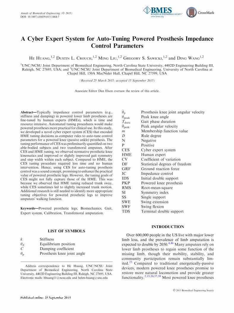
Before data collection, each subject was fit with ourpowered prosthesis. A special adaptor was made toallow able-bodied subjects to wear the prosthesis(Fig. 1). On days prior to testing, subjects trained towalk with the PKP in our lab for approximately 10 huntil they felt comfortable walking at a speed of0.6 m s21 without holding a railing.
Human Expert Tuning
In one condition, an experienced HME tuned the ICparameters of the PKP while subjects walked on atreadmill. The HME had designed the powered pros-thesis and its control algorithm. Prior to this study, hehad completed observational gait analysis and biome-chanics courses, and independently conducted param-eter tuning for twenty subjects.
Eight initial IC parameter sets in each gait phasewere defined as 1 of 8 possible arrangements of themaximum and minimum values of each parameter (seeTable 1) among fine-tuned parameters (unpublished
FIGURE 1. Powered knee prosthesis prototype with adaptorallowing able-bodied subjects to walk with the prosthesis.
TABLE 1. Initial impedance control parameter extrema val-ues.
IC parameters
Phases
IDS SS TDS SWF SWE
Stiffness, k (Nm deg21)
High 2.2 3.5 2.5 1.5 1.2
Low 1.6 2.8 0.5 1.0 0.8
Equilibrium position,
hE (degrees)
High 10 17 60 70 15
Low 4 10 30 60 5
Damping coefficient,
C (Nm deg21)
High 0.1 0.3 0.06 0.06 0.06
Low 0.01 0.01 0 0 0
Auto-Tuning Powered Prosthesis Control Parameters

data) of previous test subjects (14 able-bodied subjectsand 6 transfemoral amputees). Eight IC parameterprofiles containing initial IC parameter sets for all 5gait phases were constructed. The order of sets withineach phase was randomized using a random numbergenerator algorithm in MATLAB (The MathWorks,Inc., Natick, MA).
Subjects AB1, AB2, and TF1 completed 8 walkingtrials during which the HME tuned IC parameters. Theorder in which the eight initial IC parameter profileswere used in each trial was randomized in MATLAB,again with a random number generator algorithm.Subjects were permitted to walk for approximately10–20 strides before tuning began. The expert quali-
tatively observed subjects’ gait performance (i.e., stridelength, step symmetry, and trunk motion) and on-board sensor readings (i.e., PKP knee angle) from theprosthesis, and tuned IC parameters accordingly. ICparameter values on the prosthesis were then updatedbased on the expert’s tuning. The three procedures(observing, tuning, and updating) were conductedsequentially within each tuning cycle, which was re-peated until the expert was satisfied with the prosthesisperformance. In each tuning cycle, there was no limi-tation on how many IC parameters the expert couldadjust. Subjects walked with fine-tuned IC parametersfor 15 strides before the trial was stopped. To ensurethat the expert tuned the parameters by observationrather than memory of previous tuning results, onlyincremental tuning was permitted; true IC values werenot available to the expert during or after tuning.
Cyber Expert System Design
We designed a CES based on fuzzy logic inferencethat encoded a human expert’s knowledge and expe-rience into computer rules to tune the IC parameters ofa PKP (Fig. 2). IC parameters were tuned to reproducethe average knee angle trajectory of healthy adultsduring level ground walking,45 since normative gaitbehavior has been the target of other powered kneeprostheses.20,37 Three gait parameters, computed fromintrinsic prosthesis measurements, were used to char-acterize the knee angle trajectory in each gait phase:peak knee angle (hpeak),
5 gait phase duration (Tdura),5
and peak angular velocity ( _hpeak).6 hpeak was the max-
imum knee flexion angle for IDS, SWF, and themaximum knee extension angle for SS, SWE, and TDS._hpeak was the maximum flexion angular velocity for
IDS, TDS, and SWF and the maximum extensionangular velocity for SWE and SS.
For each gait phase (state), a fuzzy logic tuner wasdesigned using the well-known WM approach from
TABLE 2. Comparison of RMS errors at the beginning and end of trials.
Method
Subject
AB1 AB2 TF1 TF2
HME
t 2.09 2.26 2.25 –
p 0.037 0.029 0.030 –
CES
t 7.06 3.00 3.89 6.81
p <0.001 0.009 0.003 0.001
Non-tuning
t 0.86 0.80 0.41 –
p 0.209 0.226 0.348 –
Statistical comparisons were made within each subject across trials (DF = 7). Bold characters indicate statistical significance (p< 0.05);
positive t values indicate that RMS errors decreased from the beginning to the end of the trials.
FIGURE 2. Block diagram of cyber expert system (CES) tu-ner based on fuzzy logic, within the impedance controlframework. The CES adjusted impedance control parameters(Dk, DhE, and DC) based on the interpretation of knee trajec-tory error by the fuzzy tuner
HUANG et al.

Wang and Mendel41 that has been widely used in otherapplications.12,22 This approach was chosen because itpermits an adaptive, expandable rule base as moretraining data become available.9 Each fuzzy tunerconsisted of a fuzzification block, rule-base, inferenceengine, and defuzzification block. During fuzzification,crisp inputs were converted into grades in individualmembership functions that determined how inputsshould be interpreted by the linguistic rules. The rule-base stored the knowledge, in the form of IF–THENrules, of how to change outputs given a set of inputs.The inference engine determined which rule to use tomap fuzzified inputs into fuzzified outputs. Thedefuzzification block converted the fuzzified outputinto crisp outputs.
The inputs of the fuzzy tuner for each gait phase
were the difference (Dhpeak, DTdura, and D _hpeak)between the prosthesis and target gait parametersaveraged across five consecutive strides. The outputswere the changes in IC parameters (Dk, DhE, and DC).Two trapezoid membership functions, negative (N)and positive (P), were defined for each input and out-put parameter, with the domain intervals of the fuzzyregions normalized by the minimum and maximumparameter values during the preliminary HME tuningexperiments. Multiplication was used for the fuzzy‘‘and’’ logic, while maximization was used for the ‘‘or’’logic. The inference was made by clipping the outputmembership function at the input strength for eachrule. The combination of outputs in multiple rules wasachieved by fuzzy ‘‘or’’ logic. Crisp outputs werecomputed using a centroid defuzzification algorithm.41
Key to designing the CES was building the fuzzyrule-base, established using data collected from theHME tuning trials for AB1, AB2, and TF1. For eachinstance when the HME adjusted the IC parameters,input–output data pairs having three inputs (Dhpeak,
DTdura, and D _hpeak) and one output (Dk, DhE, or DC)were formulated and normalized by multiplying themaximum adjustment of that impedance parameterduring HME tuning. Values in each input–output datapair were assigned to the membership function, eitherN or P, for which the projected function value, m, washigher. Rules in the form of IF–THEN statementswere then generated for each data pair (e.g., Eq. 2).
Rule : IF Dhpeak is N;DTdura is N; and
D _hpeak is P;THEN DhE is P:ð2Þ
To resolve conflicts between rules with the same IFpart but different THEN parts, a degree D was as-signed for each rule (Eq. 3), and only the rule with thehighest degree in the conflict group was accepted forthe final rule-base.
D Ruleð Þ ¼ m Dhpeak� �
m DTdurað ÞmðD _hpeakÞm DhEð Þ:ð3Þ
The final rule base (Tables A, B, C), included asElectronic Supplementary Material, contained eightrules relating inputs to each output IC parameter, or24 rules for each gait phase.
Cyber Expert Tuning
All four subjects participated in the CES tuningtrials, conducted on different days from the previousprocedures. Subjects AB1, AB2, and TF1 completed 16walking trials (8 CES tuning, 8 non-tuning), whilesubject TF2 completed 8 walking trials with CEStuning only. The same eight initial IC parameter pro-files and randomization procedure used in the HMEtuning trials were adopted here in both the tuning andnon-tuning trials. CES tuning was initiated approxi-mately 30 s after starting the trial, and IC parameterswere tuned only if specific criteria were met. To ensurethat subjects had adjusted to current IC parametervalues, the CES tuned impedance parameters if the
variance in gait parameters (hpeak, Tdura, _hpeak) over fiveconsecutive strides was less than the parameter vari-ance during walking following HME tuning. Duringonline tuning, gait parameter errors (Dhpeak, DTdura,
and4 _hpeak) averaged over the last 5 consecutive strides
were used as CES inputs. The impedance values wereupdated based on the CES outputs. The CES stoppedtuning when the root-mean-square (RMS) errorbetween the prosthesis and target knee joint anglesover five consecutive strides was less than 3�, or 1.5times the joint angle standard deviation during walkingin healthy adults.44 Subjects walked with fine-tuned ICparameters for 15 strides before the trial was stopped.
Data Analysis to Compare HME and CES TuningPerformance
We computed the RMS error between the prosthesisknee motion and target knee joint angle representingnormative knee kinematics during walking. We alsocomputed common global measures of gait perfor-mance as an indicator of subjects’ overall adaptationto the prosthesis over a trial, including stance/swingduration index, step width, and trunk sway.
Stance and swing duration symmetry, commonmeasures of general gait performance in lower limbamputees,26,40 were quantified by the symmetry index(Eq. 4), where S and P are the gait phase duration ofsubjects’ sound and prosthetic lower limbs, respec-tively.26
Auto-Tuning Powered Prosthesis Control Parameters

SI ¼ S� Pð ÞSþ Pð Þ � 0:5
ð4Þ
Step width, an indicator of stability, was computedas the medial–lateral distance between heel markers atheel strike.21 Trunk sway, another indicator of stabil-ity, was computed as the peak-to-peak distance of theT10 spinal vertebra (located with a reflective marker bymotion capture) in the lateral-medial and anterior-posterior directions during a stride cycle.3 Trunkmovement was monitored only for subjects TF1 andTF2.
As the tuning procedure progressed, we expectedthat symmetry index magnitude would decrease ifbilateral gait timing became more symmetric; stepwidth would decrease if subjects felt more stable;27 andtrunk movement would decrease if subjects’ balanceimproved.
RMS error, symmetry index, step width, and trunksway were computed for each stride and averaged over10 consecutive strides at both the beginning and end oftrials. For both CES and HME tuning methods, thesequantified metrics were compared before and aftertuning IC parameters; a one-tailed paired Student’s ttest was conducted across trials within each individualsubject. Additionally, we compared the quantifiedmetrics derived after HME tuning to those derivedafter CES tuning using two-tailed paired Student’s ttests across subjects AB1, AB2, and TF1.
As a measure of the repeatability of CES and HMEtuning, we computed the coefficient of variation(CV),13 the ratio of the standard deviation to the mean,in fine-tuned IC parameters for each subject and eachgait phase. We further averaged the CV across phasesfor each subject and then compared the CV betweenHME and CES using two-tailed paired Student’s t testsacross AB1, AB2, and TF1.
For all statistical comparisons, significant differ-ences were defined for p< 0.05.
RESULTS
Both CES and HME tuning produced a more nor-mative prosthetic knee angle trajectory. For bothtuning methods, post-tuning RMS error decreasedsignificantly compared to pre-tuning RMS errors inAB1, AB2, and TF1 (see statistics in Table 2). This wasalso observed in the CES tuning trials collected fromTF2, whose data were not used to build the CES rulebase (Table 2; Fig. 3). For non-tuning trials withineach subject, we observed a slight, but non-significant,reduction of RMS errors at the end of the trials (Ta-ble 2), indicating that improvement in knee angle tra-
jectory over the tuning trials was primarily due totuning rather than to subjects’ adaptation to initial ICparameters. CES tuning yielded smaller RMS errorsthan HME tuning, consistently observed in AB1, AB2,and TF1. Compared to RMS errors after HME tuningaveraged across subjects, RMS errors after CES tuning(Fig. 3) showed more consistent and lower values.However, the post-tuning RMS error differencebetween CES and HME tuning trials was not statisti-cally significant across 3 tested subjects (p = 0.210,t = 1.82, DF = 2) (Fig. 3).
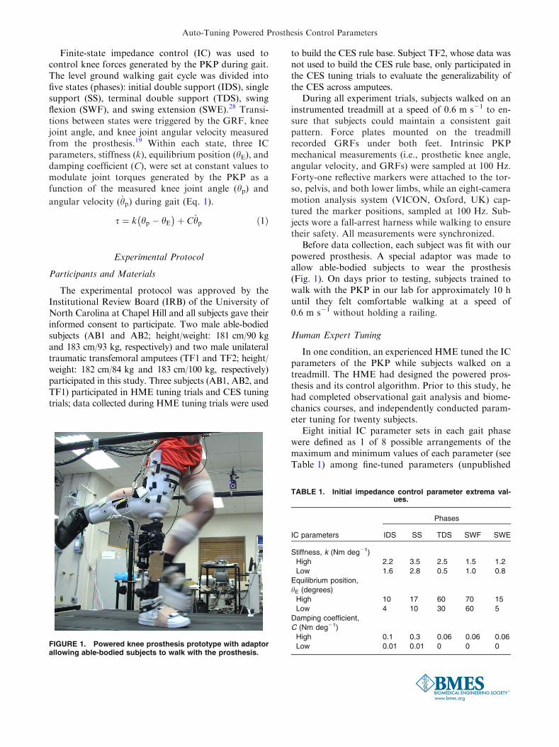
Stance and swing duration symmetry improvedsignificantly after HME tuning for subjects AB1, AB2,and TF1 (Table 3). The gait symmetry of each testedsubject also improved after CES tuning, but not allimprovements were statistically significant (Table 3).There was no difference in the subjects’ post-tuningstance (p = 0.916, t = 0.12, DF = 2) or swing(p = 0.868, t = 0.19, DF = 2) duration symmetrybetween HMS and CES tuning trials (Fig. 4).
Both HME tuning and CES tuning reduced the stepwidth of each subject (Table 4; Fig. 5). The step widthreductions were statistically significant for all subjectswho participated in HME tuning, while reductionsfrom CES tuning were significant only for subjectsAB1 and TF2 (Table 4). Compared with HME, CESyielded comparable post-tuning step width averagedacross 3 subjects (p = 0.518, t = 0.78, DF = 2)(Fig. 5).
The trunk sway was captured from TF1 duringHME and CES tuning, and from TF2 during CEStuning only. For TF1, HME tuning significantly re-duced trunk sway in the lateral–medial (p = 0.022,t = 2.45, DF = 7) and anterior–posterior (p = 0.007,
FIGURE 3. Mean (6SD) RMS error between prosthetic kneeand target knee angle trajectories before and after tuning. ForHME and CES tuning, RMS errors were averaged across trialsfirst; the showed mean (6SD) was averaged across threesubjects. TF2’s data, which were not used to build CES, wasaveraged over eight CES tuning trials.
HUANG et al.
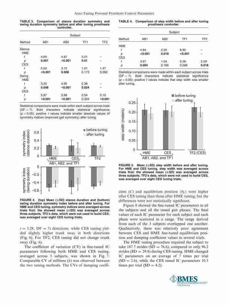
t = 3.28, DF = 7) directions, while CES tuning yiel-ded slightly higher trunk sway in both directions(Fig. 6). For TF2, CES tuning did not change trunksway (Fig. 6).
The coefficient of variation (CV) in fine-tuned ICparameters following both HME and CES tuning,averaged across 3 subjects, was shown in Fig. 7.Comparable CV of stiffness (k) was observed betweenthe two tuning methods. The CVs of damping coeffi-
cient (C) and equilibrium position ðhEÞ were higherafter CES tuning than those after HME tuning, but thedifferences were not statistically significant.
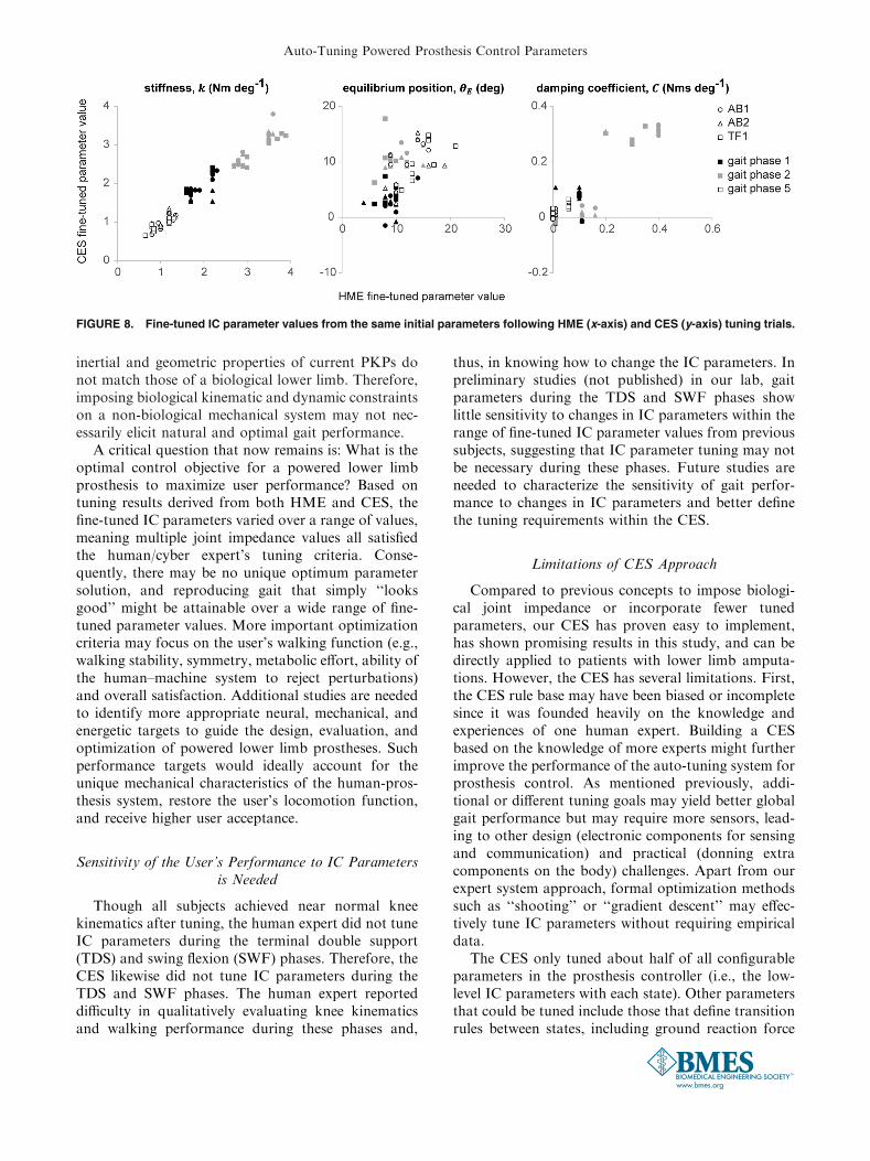
Figure 8 showed the fine-tuned IC parameters in allthe subjects and all the tuned gait phases. The finalvalues of each IC parameter for each subject and eachphase were scattered in a range. The range derivedfrom each of the 3 subjects overlapped one another.Qualitatively, there was relatively poor agreementbetween CES and HME fine-tuned equilibrium posi-tion and damping coefficient values in several trials.
The HME tuning procedure required the subject totake 187.7 strides (SD = 76.6), compared to only 96.2strides (SD = 29.8) during CES tuning. HME changedIC parameters on an average of 7 times per trial(SD = 2.6), while the CES tuned IC parameters 10.3times per trial (SD = 4.2).
TABLE 3. Comparison of stance duration symmetry andswing duration symmetry before and after tuning prosthesis
controller.
Method
Subject
AB1 AB2 TF1 TF2
Stance
HME
t 4.69 4.97 3.01 –
p 0.001 <0.001 0.01 –
CES
t 5.02 3.15 1.01 1.47
p <0.001 0.008 0.173 0.092
Swing
HME
t 3.20 4.95 2.39 –
p 0.008 <0.001 0.024 –
CES
t 5.87 5.88 0.54 5.10
p <0.001 <0.001 0.304 <0.001
Statistical comparisons were made within each subject across trials
(DF = 7). Bold characters indicate statistical significance
(p< 0.05); positive t values indicate smaller absolute values of
symmetry indices (improved gait symmetry) after tuning.
TABLE 4. Comparison of step width before and after tuningprosthesis controller.
Method
Subject
AB1 AB2 TF1 TF2
HME
t 4.84 2.55 6.90 –
p <0.001 0.019 <0.001 –
CES
t 3.67 1.04 0.56 2.59
p 0.004 0.166 0.298 0.018
Statistical comparisons were made within each subject across trials
(DF = 7). Bold characters indicate statistical significance
(p< 0.05); positive t values indicate that step width was smaller
after tuning.
FIGURE 4. (top) Mean (6SD) stance duration and (bottom)swing duration symmetry index before and after tuning. ForHME and CES tuning, symmetry indices were averaged acrosstrials first; the showed mean (6SD) was averaged acrossthree subjects. TF2’s data, which were not used to build CES,was averaged over eight CES tuning trials.
FIGURE 5. Mean (6SD) step width before and after tuning.For HME and CES tuning, step width was averaged acrosstrials first; the showed mean (6SD) was averaged acrossthree subjects. TF2’s data, which were not used to build CES,was averaged over eight CES tuning trials.
Auto-Tuning Powered Prosthesis Control Parameters
DISCUSSION
Cyber Expert System (CES) is a Potentially Cost-Effective Approach for Tuning Impedance Control
Parameters of Powered Prostheses
Proficient and cost-effective automatic tuning sys-tems are needed to improve the clinical viability ofmodern powered prosthetic devices while enablingmore natural walking ability. We developed a rule-based CES that automatically tuned the impedancecontrol (IC) parameters of a prototype powered kneeprosthesis and closely reproduced an able-bodied kneeangle trajectory during level-ground walking. Com-pared to manual HME tuning, CES tuning can achievecomparable performance quickly without human
expert intervention. Ideally, fine-tuning IC parameterswith our CES only requires the amputee user to donthe powered prosthesis and walk on level ground forseveral minutes, even outside of the clinical setting,e.g., at home. The CES might then enable the pros-thesis to facilitate user adaptation over time by tuningIC parameters either continuously or periodicallywhen initiated by the user. Therefore, our CES mightreduce the number of clinical visits and, consequently,healthcare costs for lower limb amputees.
Determining the Prosthesis Control Objective is Critical
Not surprisingly, the CES tracked the normativeknee trajectory more precisely than the HME by tun-ing based on quantitative measures rather than quali-tative observation. This was observed in all 3 subjectswho participated in both the CES and HME tuningtrials, although the difference was not statisticallysignificant due to the limited number of human sub-jects involved in this pilot evaluation. Overall, the CEStuning improved or slightly improved gait symmetryand step width in all the subjects. Additionally, therepeatability of CES tuning was comparable to that ofHME tuning. However, trunk sway was not reducedafter CES tuning as it was following HME tuning,indicating that the human expert’s tuning goals mayextend beyond the CES’s goal of reproducing norma-tive knee joint kinematics. This implication might alsobe reflected through the relative disagreement betweenHME and CES fine-tuned IC parameters (Fig. 8).Furthermore, though joint kinematics and impedanceof able-bodied subjects have been the target of otherpowered prosthesis controllers,36,37 the additionalsocket-limb interface, joint mechanics, and segment
FIGURE 6. Mean (6SD) trunk sway before and after tuning. Trunk sway was only measured for subjects TF1 and TF2. TF2 onlyparticipated in CES tuning procedure. Hence, the results were averaged across eight trials of each tuning method for each subject.* denotes statistical significance (p<0.05).
FIGURE 7. Mean (6SD) coefficient of variation (CV) of fine-tuned IC parameters following HME and CES tuning. The re-sults were averaged across the three tuned gait phases, thenaveraged across three subjects (AB1, AB2, and TF1).
HUANG et al.
inertial and geometric properties of current PKPs donot match those of a biological lower limb. Therefore,imposing biological kinematic and dynamic constraintson a non-biological mechanical system may not nec-essarily elicit natural and optimal gait performance.
A critical question that now remains is: What is theoptimal control objective for a powered lower limbprosthesis to maximize user performance? Based ontuning results derived from both HME and CES, thefine-tuned IC parameters varied over a range of values,meaning multiple joint impedance values all satisfiedthe human/cyber expert’s tuning criteria. Conse-quently, there may be no unique optimum parametersolution, and reproducing gait that simply ‘‘looksgood’’ might be attainable over a wide range of fine-tuned parameter values. More important optimizationcriteria may focus on the user’s walking function (e.g.,walking stability, symmetry, metabolic effort, ability ofthe human–machine system to reject perturbations)and overall satisfaction. Additional studies are neededto identify more appropriate neural, mechanical, andenergetic targets to guide the design, evaluation, andoptimization of powered lower limb prostheses. Suchperformance targets would ideally account for theunique mechanical characteristics of the human-pros-thesis system, restore the user’s locomotion function,and receive higher user acceptance.
Sensitivity of the User’s Performance to IC Parametersis Needed
Though all subjects achieved near normal kneekinematics after tuning, the human expert did not tuneIC parameters during the terminal double support(TDS) and swing flexion (SWF) phases. Therefore, theCES likewise did not tune IC parameters during theTDS and SWF phases. The human expert reporteddifficulty in qualitatively evaluating knee kinematicsand walking performance during these phases and,
thus, in knowing how to change the IC parameters. Inpreliminary studies (not published) in our lab, gaitparameters during the TDS and SWF phases showlittle sensitivity to changes in IC parameters within therange of fine-tuned IC parameter values from previoussubjects, suggesting that IC parameter tuning may notbe necessary during these phases. Future studies areneeded to characterize the sensitivity of gait perfor-mance to changes in IC parameters and better definethe tuning requirements within the CES.
Limitations of CES Approach
Compared to previous concepts to impose biologi-cal joint impedance or incorporate fewer tunedparameters, our CES has proven easy to implement,has shown promising results in this study, and can bedirectly applied to patients with lower limb amputa-tions. However, the CES has several limitations. First,the CES rule base may have been biased or incompletesince it was founded heavily on the knowledge andexperiences of one human expert. Building a CESbased on the knowledge of more experts might furtherimprove the performance of the auto-tuning system forprosthesis control. As mentioned previously, addi-tional or different tuning goals may yield better globalgait performance but may require more sensors, lead-ing to other design (electronic components for sensingand communication) and practical (donning extracomponents on the body) challenges. Apart from ourexpert system approach, formal optimization methodssuch as ‘‘shooting’’ or ‘‘gradient descent’’ may effec-tively tune IC parameters without requiring empiricaldata.
The CES only tuned about half of all configurableparameters in the prosthesis controller (i.e., the low-level IC parameters with each state). Other parametersthat could be tuned include those that define transitionrules between states, including ground reaction force
FIGURE 8. Fine-tuned IC parameter values from the same initial parameters following HME (x-axis) and CES (y-axis) tuning trials.
Auto-Tuning Powered Prosthesis Control Parameters
thresholds distinguishing swing and stance phases, andknee angles and angular velocities distinguishing pha-ses within swing and stance. Future studies shouldexplore whether tuning parameters related to the finite-state transition rules further improves gait perfor-mance.
Limitation of this Study
One limitation of this study was that we only eval-uated 3 measures of gait performance: temporal sym-metry, stance width, and trunk sway. Better criteria forevaluating and rating PKP gait performance, includingmeasures that reflect global human–prosthesis inter-action effects, are needed (e.g., lower limb jointmechanical power distribution, metabolic cost). An-other limitation was that only four human subjectswere involved in this study to demonstrate the feasi-bility of CES. The limited sample size constrained thestatistical analysis power. In addition, we only testedone transfemoral amputee subject whose data was notused to build the fuzzy rule base in the CES, so it isunclear whether the CES rule base is generalizableacross the amputee population; more subjects need tobe tested. Finally, in this study, we only demonstrateda CES design based on fuzzy logic inference. Otheradaptive structures, such as case-based reasoning orneural network, might be worth exploring in futureCES designs since they permit the expert system tolearn from previous successful examples rather thanrely on a fixed rule-base.
The CES only tuned IC parameters for a singleactuated joint (knee). In contrast, prostheses withpowered knee and ankle joints may enable more nat-ural walking but present an even greater tuning chal-lenge that would greatly benefit from a CES. It remainsto be seen whether human manual tuning proficiency issufficient to build an effective CES for multi-powered-joint prostheses.
Conclusions
In conclusion, we developed a cyber expert system(CES) that uses fuzzy logic inference methods toeffectively tune the impedance control parameters of apowered knee prosthesis (PKP) during level-groundwalking. While restoring normative knee kinematicsgenerally improved subjects’ overall gait performance,greater gains may be achieved by considering additionalneural, biomechanical, or energetics measurements inthe tuning decisions made by the CES. Given its effec-tiveness and potential generalizability, the CES ispotentially a powerful clinical tool that could makePKPs more practical and accessible for widespread use.
ELECTRONIC SUPPLEMENTARY MATERIAL
The online version of this article (doi:10.1007/s10439-015-1464-7) contains supplementarymaterial, which is available to authorized users.
ACKNOWLEDGMENTS
The authors would like to thank Derek Frankenaand Stephen Harper of Atlantic Prosthetics and Or-thotics and Michael Astilla of Bio-Tech Prostheticsand Orthotics for fitting our study participants withprosthetic adaptors and sockets. We also thank Wil-liam Boatwright for assisting with data collection andAndrea Brandt, Dr. Jon Stallings, and Dr. ConsueloArellano for assisting with statistical analysis. Thiswork was partly funded by a seed grant from theUNC/NCSU Rehabilitation Engineering Core, and bythe National Science Foundation (NSF #1361549,1406750, and 1527202).
CONFLICT OF INTEREST
No benefits in any form have been or will be re-ceived from a commercial party related directly orindirectly to the subject of this manuscript.
REFERENCES
1Badiru, A. B., and J. Cheung. Fuzzy Engineering ExpertSystems with Neural Network Applications. New York:Wiley, 2002.2Borjian, R., J. Lim, M. B. Khamesee and W. Melek. Thedesign of an intelligent mechanical active prosthetic knee.In Proceedings of 34th Conference on IEEE IndustrialElectronics Society, 2008, pp. 2918–2923.3Dingwell, J. B., and L. C. Marin. Kinematic variability andlocal dynamic stability of upper body motions whenwalking at different speeds. J. Biomech. 39:444–452, 2006.4Fletcher, D. D., K. L. Andrews, J. W. Hallett, Jr, M. A.Butters, C. M. Rowland, and S. J. Jacobsen. Trends inrehabilitation after amputation for geriatric patients withvascular disease: implications for future health resourceallocation. Arch. Phys. Med. Rehabil. 83:1389–1393, 2002.5Giannini, S. Gait Analysis: Methodologies and ClinicalApplications. Amsterdam: IOS Press for BioengineeringTechnical & Systems, 1994.6Granata, K. P., M. F. Abel, and D. L. Damiano. Jointangular velocity in spastic gait and the influence of muscle-tendon lengthening. J. Bone Joint Surg. Am. 82A:174–186,2000.7Gregg, R. D., T. Lenzi, L. J. Hargrove, and J. W. Sen-singer. Virtual constraint control of a powered prostheticleg: from simulation to experiments with transfemoralamputees. IEEE Trans. Robot. 30:1455–1471, 2014.
HUANG et al.
8Gregg, R. D., T. Lenzi, N. P. Fey, L. J. Hargrove and J. W.Sensinger. Experimental effective shape control of a pow-ered transfemoral prosthesis. In IEEE International Con-ference on Rehabilitation Robotics, 2013.9Guillaume, S. Designing fuzzy inference systems from data:an interpretability—oriented review. IEEE Trans. FuzzySyst. 9:426–443, 2001.
10Herr, H., and A. Wilkenfeld. User-adaptive control of amagnetorheological prosthetic knee. Ind. Robot 30:42–55,2003.
11Holgate, M. A., T. G. Sugar and A. W. Bohler. A novelcontrol algorithm for wearable robotics using phase planeinvariants. In Proceedings of IEEE International Confer-ence on Robot Automation, 2009, pp. 3845–3850.
12Huang, S.-J., and J.-S. Lee. A stable self-organizing fuzzycontroller for robotic motion control. IEEE Trans. Ind.Electron. 47:421–428, 2000.
13Kadaba, M. P., H. K. Ramakrishnan, M. E. Wootten, J.Gainey, G. Gorton, and G. V. Cochran. Repeatability ofkinematic, kinetic, and electromyographic data in normaladult gait. J. Orthop. Res. 7:849–860, 1989.
14Kearney, R. E., and I. W. Hunter. System-identification ofhuman joint dynamics. Crit. Rev. Biomed. Eng. 18:55–87,1990.
15Lambrecht, B. G. A. and H. Kazerooni. Design of a Semi-Active Knee Prosthesis. In IEEE International Conferenceon Robotics, 2009, pp. 4097–4103.
16Lawson, B. E., B. Ruhe, A. Shultz, and M. Goldfarb. Apowered prosthetic intervention for bilateral transfemoralamputees. IEEE Trans. Biomed. Eng. 62:1042–1050, 2015.
17Lenzi, T., L. J. Hargrove and J. W. Sensinger. Minimumjerk swing control allows variable cadence in poweredtransfemoral prostheses. In Conference Proceedings IEEEEngineering in Medicine and Biology Society, 2014, pp.2492–2495.
18Liu, M., P. Datseris and H. Huang. A prototype for smartprosthetic legs: analysis and mechanical design. In Pro-ceedings of International Conference on Control RoboticsCybernetics, 2011, pp. 139–143.
19Liu, M., F. Zhang, P. Datseris, and H. Huang. Improvingfinite state impedance control of active transfemoral pros-theses using Dempster-Shafer state transition rules. J. In-tell. Robot. Syst. 76:461–474, 2014.
20Martinez-Vilialpando, E. C., and H. Herr. Agonist-antag-onist active knee prosthesis: a preliminary study in level-ground walking. J. Rehabil. Res. Dev. 46:361–373, 2009.
21McAndrew Young, P. M., and J. B. Dingwell. Voluntarilychanging step length or step width affects dynamic stabilityof human walking. Gait Posture 35:472–477, 2012.
22Melingui, A., C. R. Merzouki and J. B. Mbede. Adaptivenavigation of an omni-drive autonomous mobile robot inunstructured dynamic environments. In Proceedings ofIEEE International Conference on Robot Biomimetics,2013, pp. 1924–1929.
23Miller, W. C., A. B. Deathe, M. Speechley, and J. Koval.The influence of falling, fear of falling, and balance confi-dence on prosthetic mobility and social activity amongindividuals with a lower extremity amputation. Arch. Phys.Med. Rehabil. 82:1238–1244, 2001.
24Mirbagheri, M. M., H. Barbeau, and R. E. Kearney.Intrinsic and reflex contributions to human ankle stiffness:variation with activation level and position. Exp. Brain Res.135:423–436, 2000.
25Negnevitsky, M. Artificial Intelligence: A Guide to Intelli-gent Systems. Essex: Pearson Education, 2005.
26Nolan, L., A. Wit, K. Dudzinski, A. Lees, M. Lake, and M.Wychowanski. Adjustments in gait symmetry with walkingspeed in trans-femoral and trans-tibial amputees. GaitPosture 17:142–151, 2003.
27Orendurff, M. S., A. D. Segal, G. K. Klute, J. S. Berge, E.S. Rohr, and N. J. Kadel. The effect of walking speed oncenter of mass displacement. J. Rehabil. Res. Dev. 41:829–834, 2004.
28Perry, J. Gait Analysis: Normal and Pathological Function.Thorofare: SLACK Inc., 1992.
29Pfeifer, S., R. Riener and H. Vallery. Knee stiffness esti-mation in physiological gait. In Conference ProceedingsIEEE Engineering in Medicine and Biology Society, 2014,pp. 1607–1610.
30Pfeifer, S., H. Vallery, M. Hardegger, R. Riener, and E. J.Perreault. Model-based estimation of knee stiffness. IEEETrans. Biomed. Eng. 59:2604–2612, 2012.
31Rouse, E. J., L. J. Hargrove, E. J. Perreault, and T. A.Kuiken. Estimation of human ankle impedance during thestance phase of walking. IEEE Trans. Neural Syst. Rehabil.Eng. 22:870–878, 2014.
32Shamaei, K., G. S. Sawicki, and A. M. Dollar. Estima-tion of quasi-stiffness and propulsive work of the humanankle in the stance phase of walking. PLoS One 8:e59935,2013.
33Shamaei, K., G. S. Sawicki, and A. M. Dollar. Estimationof quasi-stiffness of the human hip in the stance phase ofwalking. PLoS One 8:e81841, 2013.
34Shamaei, K., G. S. Sawicki, and A. M. Dollar. Estimationof quasi-stiffness of the human knee in the stance phase ofwalking. PLoS One 8:e59993, 2013.
35Siler, W., and J. J. Buckley. Fuzzy Expert Systems andFuzzy Reasoning. Hoboken: Wiley, 2005.
36Simon, A. M., K. A. Ingraham, N. P. Fey, S. B. Finucane,R. D. Lipschutz, A. J. Young, and L. J. Hargrove. Con-figuring a powered knee and ankle prosthesis for trans-femoral amputees within five specific ambulation modes.PLoS One 9:e99387, 2014.
37Sup, F., A. Bohara, and M. Goldfarb. Design and controlof a powered transfemoral prosthesis. Int. J. Robot. Res.27:263–273, 2008.
38Sup, F., H. A. Varol, J. Mitchell, T. J. Withrow, and M.Goldfarb. Preliminary evaluations of a self-containedanthropomorphic transfemoral prosthesis. IEEE/ASMETrans. Mechatron. 14:667–676, 2009.
39Torrealba, R. R., G. Fernandez-Lopez, and J. C. Grieco.Towards the development of knee prostheses: review ofcurrent researches. Kybernetes 37:1561–1576, 2008.
40Tura, A., M. Raggi, L. Rocchi, A. G. Cutti, and L. Chiari.Gait symmetry and regularity in transfemoral amputeesassessed by trunk accelerations. J. Neuroeng. Rehabil. 7:4,2010.
41Wang, L. X., and J. M. Mendel. Generating fuzzy rules bylearning from examples. IEEE Trans. Syst. Man Cybern.22:1414–1427, 1992.
42Weiss, P. L., R. E. Kearney, and I. W. Hunter. Positiondependence of ankle joint dynamics—I. Passive Mech.19:727–735, 1986.
43Weiss, P. L., R. E. Kearney, and I. W. Hunter. Positiondependence of ankle joint dynamics—II. Active Mech.19:737–751, 1986.
Auto-Tuning Powered Prosthesis Control Parameters

44Winter, D. A. Kinematic and kinetic patterns in humangait: variability and compensating effects. Hum. Mov. Sci.3:51–76, 1984.
45Winter, D. A. The Biomechanics and Motor Control ofHuman Gait. Waterloo: University of Waterloo Press,1987.
46Ziegler-Graham, K., E. J. MacKenzie, P. L. Ephraim, T.G. Travison, and R. Brookmeyer. Estimating the preva-lence of limb loss in the United States: 2005 to 2050. Arch.Phys. Med. Rehabil. 89:422–429, 2008.
HUANG et al.


![Development of an Active Powered Prosthesis System using ...ecsl.inha.ac.kr/publication/ICROS2017_b.pdf · 휴머노이드 등의 로봇기술과 연계할 수 있다[10]. 본 논문은](https://static.fdocuments.net/doc/165x107/5e32ac6bd617b96e9a2df73f/development-of-an-active-powered-prosthesis-system-using-ecslinhaackrpublicationicros2017bpdf.jpg)


![INDEX [microdentsystem.com] · INTRODUCTION REMOVABLE AND IMMEDIATE . PROSTHESIS MULTIPLE PROSTHESIS. CEMENTED PROSTHESIS. Microdent Genius conical (straight) abutment or Microdent](https://static.fdocuments.net/doc/165x107/5facd9ef77a5ed547a36b19e/index-introduction-removable-and-immediate-prosthesis-multiple-prosthesis.jpg)
