A Computer-Aided Music Composition Application · PDF fileA Computer-Aided Music Composition...
82
A Computer-Aided Music Composition Application Using 3D Graphics - Research and Initial Design Gretchen Dickie A Project Submitted to the Department of Computer Science Montana State University – Bozeman in Partial Fulfillment of the Requirements for the Degree of Master of Science in Computer Science
-
Upload
nguyennguyet -
Category
Documents
-
view
221 -
download
1
Transcript of A Computer-Aided Music Composition Application · PDF fileA Computer-Aided Music Composition...

A Computer-Aided Music Composition Application
Using 3D Graphics - Research and Initial Design
Gretchen Dickie
A Project Submitted to the Department of Computer Science
Montana State University – Bozeman
in Partial Fulfillment of the Requirements for the Degree of
Master of Science in Computer Science

1
Table of Contents TABLE OF CONTENTS ............................................................................................................................................0
LIST OF FIGURES .....................................................................................................................................................3 ACKNOWLEDGEMENTS .........................................................................................................................................4 ABSTRACT .................................................................................................................................................................5 1. BACKGROUND .....................................................................................................................................................6 2. INTRODUCTION ....................................................................................................................................................8 3. RELATED WORK ................................................................................................................................................13
3.1 LITERATURE REVIEW ......................................................................................................................................13
3.1.1 “Visualization of Music” .........................................................................................................................13 3.1.2 “Performance Visualization – A New Challenge to Music through Visualization”..............................15 3.1.3 Visualizing Mood in Music ......................................................................................................................16 3.1.4 21st Century Virtual Color Organ ............................................................................................................18
3.2 SURVEY OF EXISTING PRODUCTS ....................................................................................................................21
3.2.1 Creating Music .........................................................................................................................................21 3.2.2 Coagula – Industrial Strength Color-Note Organ ..................................................................................22 3.2.3 DrawSound...............................................................................................................................................23 3.2.4 Music Draw ..............................................................................................................................................24 3.2.5 Visual Orchestra ......................................................................................................................................25 3.2.6 ArtSong.....................................................................................................................................................26 3.2.7 PitchWeb ..................................................................................................................................................27 3.2.8 Hyperscore................................................................................................................................................28
4. METHODOLOGIES AND IMPLEMENTATION...............................................................................................31
4.1 INITIAL DESIGN ................................................................................................................................................31
4.1.1 User/Display Module................................................................................................................................31 4.1.2 Graphics Module......................................................................................................................................34 4.1.3 Sound Synthesis Module..........................................................................................................................39 4.1.4 Mapping Module ......................................................................................................................................43
4.1.4.1 Graphics Module/Mapping Module Interface ................................................................................................ 43 4.1.4.2 Mapping Module/Sound Synthesis Module Interface .................................................................................... 44 4.1.4.3 Mapping Strategies ........................................................................................................................................... 45
2
4.2 SQUEAK .................................................................................................................................................................47
4.2.1 The Squeak Language and Environment................................................................................................47 4.2.2 Squeak Graphics ......................................................................................................................................53 4.2.3 Squeak Sound...........................................................................................................................................56 4.2.4 Mapping Module and Squeak..................................................................................................................57 4.2.5 Squeak Prototype......................................................................................................................................58
4.2.5.1 Object Editor Window ...................................................................................................................................... 59 4.2.5.2 Envelope Editor Window.................................................................................................................................. 60 4.2.5.3 Scene Composition Window ............................................................................................................................. 61
5. RESULTS ..............................................................................................................................................................62 6. FUTURE WORK...................................................................................................................................................63 7. CONCLUSIONS ...................................................................................................................................................64 APPENDIX A.............................................................................................................................................................65 GLOSSARY...............................................................................................................................................................73 REFERENCES..........................................................................................................................................................77
3
List of Figures Figure 1: Pitch mapping .............................................................................................................................................9 Figure 2: Duration mapping.......................................................................................................................................9 Figure 3: Volume mapping .......................................................................................................................................10 Figure 4: Timbre mapping .......................................................................................................................................10 Figure 5: Project Diagram........................................................................................................................................11 Figure 6: Representation of Smith’s and Williams’ coordinate mapping system................................................14 Figure 7: Overhead view of figure 6 ........................................................................................................................14 Figure 8: comp-i scene visualizing the whole piece of music..................................................................................15 Figure 9: comp-i zoomed view of scene....................................................................................................................15 Figure 10: Particle system “fountain” object ..........................................................................................................16 Figure 11: Kate Hevner’s adjective circle ...............................................................................................................17 Figure 12: Revised mood chart with emotion centers ............................................................................................18 Figure 13: Still shot from the Color Organ showing musical structure generated by Clarence Barlow’s “Im Januar am Nil” ................................................................................................19 Figure 14: Still shot from the Color Organ showing musical structure generated by piano chords..................20 Figure 15: Musical Sketch Pad interface of Creating Music software..................................................................22 Figure 16: Coagula – Industrial Strength Color-Note Organ................................................................................23 Figure 17: DrawSound GUI......................................................................................................................................24 Figure 18: Music Draw 3.2........................................................................................................................................25 Figure 19: Visual Orchestra .....................................................................................................................................26 Figure 20: ArtSong....................................................................................................................................................27 Figure 21: PitchWeb..................................................................................................................................................28 Figure 22: HyperScore ..............................................................................................................................................29 Figure 23: GLUI window showing available widgets .............................................................................................33 Figure 24: GLUI window with subwindow .............................................................................................................33 Figure 25: Free Form Deformation of a 3D object using lattice control points ...................................................34 Figure 26: Blender user interface.............................................................................................................................35 Figure 27: Blender object deformation....................................................................................................................36 Figure 28: 3D Canvas user interface........................................................................................................................37 Figure 29: 3D Canvas object deformation...............................................................................................................37 Figure 30: Amorphium object deformation ............................................................................................................38 Figure 31: Oscillator waveforms ..............................................................................................................................39 Figure 32: ADSR envelope........................................................................................................................................40 Figure 33: SubSynth..................................................................................................................................................41 Figure 34: SawCutter ................................................................................................................................................42 Figure 35: Mapping object parameters to an ADSR envelope ..............................................................................46 Figure 36: Squeak Worlds ........................................................................................................................................49 Figure 37: Squeak workspace tools..........................................................................................................................50 Figure 38: Morphic object halo................................................................................................................................51 Figure 39: Morphic user-scripting...........................................................................................................................53 Figure 40: Creating 3D objects in Squeak with Wonderland................................................................................55 Figure 41: Squeak Sound Tools................................................................................................................................57 Figure 42: Squeak Prototype ....................................................................................................................................58 Figure 43: Object Editor Window ...........................................................................................................................59 Figure 44: Envelope Editor Window .......................................................................................................................60 Figure 45: Scene Composition Window...................................................................................................................61

4
Acknowledgements To my advisor, Professor Ray Babcock – thank you for all of the support and advice over these many years, and for giving me the opportunity to work on this project. To Professors Denbigh Starkey and Rocky Ross – thank you for your time, effort, and valuable input. As always, all my thanks and love to my family – Scott, Matthew, and Rachel – thank you for your understanding and for always being there to remind me what’s really important in life.
5
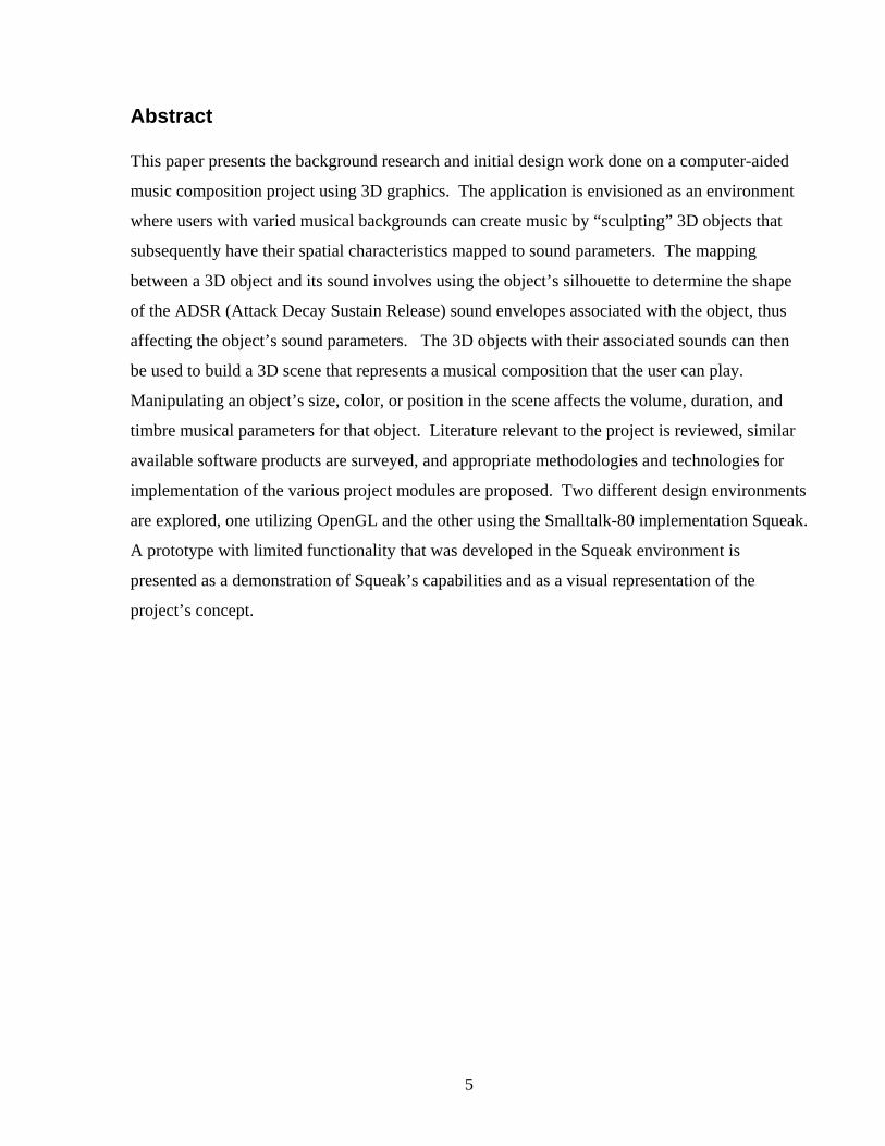
Abstract This paper presents the background research and initial design work done on a computer-aided
music composition project using 3D graphics. The application is envisioned as an environment
where users with varied musical backgrounds can create music by “sculpting” 3D objects that
subsequently have their spatial characteristics mapped to sound parameters. The mapping
between a 3D object and its sound involves using the object’s silhouette to determine the shape
of the ADSR (Attack Decay Sustain Release) sound envelopes associated with the object, thus
affecting the object’s sound parameters. The 3D objects with their associated sounds can then
be used to build a 3D scene that represents a musical composition that the user can play.
Manipulating an object’s size, color, or position in the scene affects the volume, duration, and
timbre musical parameters for that object. Literature relevant to the project is reviewed, similar
available software products are surveyed, and appropriate methodologies and technologies for
implementation of the various project modules are proposed. Two different design environments
are explored, one utilizing OpenGL and the other using the Smalltalk-80 implementation Squeak.
A prototype with limited functionality that was developed in the Squeak environment is
presented as a demonstration of Squeak’s capabilities and as a visual representation of the
project’s concept.

6
Music is the electrical soil in which the spirit lives, thinks, and invents. Ludvig von Beethoven What good are computers? They can only give you answers. Pablo Picasso 1. Background Sound has always been an integral component of computer systems, with the earliest models
using noises as indicators of the main processor’s operation status – a set of random tones may
have signaled a program running successfully, while a warning pitch prompted a shutdown.
While this sound output in no way resembled music, it did establish an audio interaction between
computers and their users. Computer music as we know it today was initiated by Max Mathews
of Bell Labs when he created his MUSIC software in 1957. The first version of MUSIC played
single line tunes and took approximately an hour on the most powerful computers available to
generate a minute of music. Many researchers and developers used MUSIC as the foundation to
take them down varied paths in computer music, but the limitations of early computers forced
most work to be done at research centers that had access to the computing power required [1].
The advent of the microprocessor in 1971 and the first personal computer with a graphical user
interface in 1984 [2] opened up the world of computer music to anyone interested in exploring
the sounds a computer can make.
Computers became capable of displaying 3D graphics in1959 when General Motors and IBM
developed DAC-1 (Design Augmented by Computers). DAC-1 was designed to accept the input
of 3D automobile specifications into the computer, which then allowed the user to rotate and
view the model from different perspectives. Sketchpad, a program created by Ivan Sutherland of
MIT in 1961, was the first computer drawing program that facilitated a direct graphical user
interface. A light pen with a photoelectric cell in its tip was used to draw shapes on the computer
screen that could be saved and recalled later [2]. The wide availability of personal computers
and the increase in their processing power over the last thirty years have prompted the explosion
of computer graphics software that can be used by anyone.

7
In 1992 Ray Babcock, adjunct assistant professor in the Computer Science department of
Montana State University-Bozeman, was attending a paper presentation at a Siggraph conference
in Chicago where the presenter was playing three “virtual instruments”. The 3D glasses and
virtual reality hood he used projected a display overhead that gave the audience a view of the
instruments suspended in space: combinations of wind instruments, keyboards, and other
graphical shapes. The instruments were manipulated by tracking his hand movements with
tracked gloves. To cause one of the instruments to become the major voice in the sounds being
created, he would draw that instrument towards him. “Physical” manipulation of the instrument
such as pounding, pressing, or stroking, produced a variety of different sounds. As Ray watched
the display, this visual correspondence between graphical objects and sound suggested to him a
mapping of some sort between the various characteristics of computer graphics and music. Over
the next ten years, he contemplated developing software that would merge computer graphics
and music into a product that would allow users to compose music by manipulating graphical
objects – without extensive musical knowledge. In 2002 Ray compiled a document detailing his
concept and preliminary ideas for the product [Appendix A], and he offered me the opportunity
to begin working on the research and initial design as a Master’s project. My interest in, and
Ray’s consideration of me for, this project stemmed from my experience as a musician: I have
been an oboist for thirty years, am currently a member of the Bozeman Symphony Orchestra,
and play with a symphony-sponsored oboe trio called OBOZE.
A subset of the initial design was identified as a potential starting point to the project, and I
began the background research in September 2003 and continued working on the design process
during spring semester of 2004. If complete implementation of this product is to be achieved, it
will require a great deal more time than has already been invested, plus a collaboration of people
with knowledge in not only music, but also artificial intelligence systems. This paper presents
the background research completed and the initial work done on selected modules of the project.

8
2. Introduction
The initial concept of this project envisioned a number of interconnected modules [Appendix A]:
• GUI (Graphical User Interface) – User/Display Module
The GUI will serve as the interface between the user, the display, and the graphics
module. Initially a 2D mouse will be utilized, but 3D input devices will also be
explored for future development. The user interface will be a “scene building”
system that will give the user access to 3D objects that can be created and
manipulated through the graphics module.
• Graphics Module
This module will offer tools for creation and manipulation of 3D objects, plus
options for the general display of the scene. It is envisioned as an environment
where the user can select an object that can be viewed as a “lump of clay” that can
be “sculpted” into a differently shaped 3D object that can then be mapped to a
sound by the mapping module and the graphics artificial intelligence (AI) engine.
OpenGL may be utilized as an API for this module (refer to figures 1 – 4, 6, 7).
• Graphics AI Engine
The 3D objects and the display created by the graphics module will have various
attributes available to the user, including object color, size, position, and texture.
The job of the graphics AI engine will be to provide certain rules that will be used
by the system to prevent impossible scene outputs while subtly augmenting the
operator’s design.
• Mapping Module
This module is the primary piece of the music composition system. The mapping
module will accept as input the scene created by the user, and will produce as
output the music control parameters used to create the song. An initial mapping
scheme for some of the more simple graphical/musical elements was proposed:
Pitch
Determined by the y-axis location (in a 3D right-hand coordinate system)
of the object in the scene. Figure 1 is a screenshot of an OpenGL scene
in which the purple object would be higher in pitch than the yellow.

9
Figure 1: Pitch mapping
Duration
The width of the object in the x-axis could determine the length of time
the note would be held. In figure 2, the yellow object would be
mapped to a musical note of longer duration than the purple.
Figure 2: Duration mapping
Volume
The overall size of the object could be mapped to the intensity, the
loudness or softness, of the note. The purple object in figure 3 would
correspond to a louder note than the yellow object.
X
Y
Z
Y
X
Z

10
Figure 3: Volume mapping
Timbre
The color or texture of the object could determine the musical instrument
represented by the shape. For example, the gold object in figure 4 may be
mapped to a brass instrument and the warm red ball to a woodwind sound.
Figure 4: Timbre mapping
• Sound Synthesis Module
The sound synthesis module will be responsible for taking the musical parameters
obtained from the mapping module, with input from the music AI engine, and
using these to output music.
Y
Y
X
X
Z
Z
11
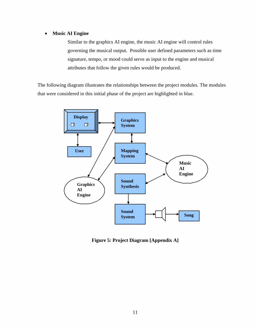
• Music AI Engine
Similar to the graphics AI engine, the music AI engine will control rules
governing the musical output. Possible user defined parameters such as time
signature, tempo, or mood could serve as input to the engine and musical
attributes that follow the given rules would be produced.
The following diagram illustrates the relationships between the project modules. The modules
that were considered in this initial phase of the project are highlighted in blue.
User
Music AI Engine
GraphicsSystem
Mapping System
Graphics AI Engine
Sound Synthesis
Display
Song Sound System
Figure 5: Project Diagram [Appendix A]
12
This portion of the project consists of three sections:
1) Survey of related work and similar projects
2) Identification of possible methodologies for the modules and interfaces considered
3) Preliminary design implementation
The first section presents a review of literature relevant to the project. This will be used to gain
insight into work that has previously been done on this subject, and may be helpful in
determining the feasibility of the project. Available software products that appear to be similar,
or related, to this project will also be examined and evaluated in this section. A survey of
existing software is necessary to insure that no products have already been developed that are
identical to the one proposed. Section two identifies the methodologies and technologies that are
required for each module and the appropriate interfaces, and examines possible tools to be used
for implementation. The first two sections will hopefully lead to the third: an initial prototype of
a simplified version of the project that allows the user, acting as the interface between the visuals
and the audio output, to compose music by manipulating graphical objects. This mapping
between computer graphics and music could enable people, even those who can’t play musical
instruments themselves, to discover their ability to become active musicians. As Gary Lee
Nelson of the Oberlin Conservatory of Music stated in his article “Who Can Be a
Composer: New Paradigms for Teaching Creative Process in Music” [3]: For most of us, music has become something to be consumed. The performance of music is left
largely to professionals. With the advent of computers and synthesizers, many of us have found
ways to return to those early days of active participation. We can perform pieces with less than
flawless technique, we can arrange our favorite tunes, and we can compose our own music
working directly with sound. Technological media have given us new folk instruments.
This project strives to demonstrate that computers can give us more than answers. Computers
can open worlds of creativity.

13
3. Related Work
The work on this project began with a review of relevant literature and a search for, and survey
of, any available similar software products. The main subject areas explored were music
visualization, computer-aided music composition, mapping of graphical objects to musical
elements (and music -> graphical objects), virtual musical instruments, and representation of
musical characteristics.
3.1 Literature Review 3.1.1 “Visualization of Music”
One of the first, and most relevant, papers encountered was “Visualization of Music”, by Sean
Smith and Glen Williams of Texas A&M University [4]. At the time it was written, the most
common method of visualizing music was standard music notation, which is the standard
representation of musical notes on a staff. While looking at a note-based or score-like
representation of a song can give a trained musician an overall idea of how a musical
composition may sound, most people don’t have experience with reading music in this way. The
goal of the authors’ project was to develop an alternate music visualization method utilizing
color and 3d space. Their program parsed MIDI data files and generated 3D graphical
representations based on the MIDI information. A mapping function was used to transform the
music data into 3D objects. The source code was written in ANSI C and OpenGL was used as
the graphics interface. Colored spheres represented tones generated by instruments, and a
sphere’s characteristics were determined by the pitch, volume and timbre of the tone. The pitch
corresponded to the note value in MIDI terms and was mapped to locations along the y-axis.
The MIDI velocity component was mapped to the volume of a tone, and the relative size of the
tone’s sphere determined its loudness/softness. Timbre is a difficult characteristic of music to
precisely describe, but the authors used sphere color to show distinctions between instrument
groups. In MIDI terms, instruments with similar timbres are in the same instrument group.
To create the 3D scene representing the MIDI data for a piece of music, Smith and Williams
defined a coordinate system where the y-axis (red) represented pitch, the individual instruments

14
were displaced evenly along the x-axis (blue), and the z-axis (green) represented time. As
spheres were generated, they were placed along the z-axis according to their start time, and they
stayed visible throughout their duration. Small colored spheres with the same hue value as the
original but with less color saturation were used as history markers to show the original’s
location and duration. The markers were scaled along the time axes according to the tone’s
duration, so a longer note would be represented by an ellipsoid [Figures 6, 7]. The origin of the
axes corresponds to a “middle-C” tone value. Two pieces of music were tested with this
visualization scheme, with the music performed using the Cakewalk sequencing program. The
instrument sounds were generated with a Yamaha QY-300 sequencer and a Roland Sound
Canvas sound module.
Figure 6: Representation of Smith Figure 7: Overhead view of and Williams’ coordinate mapping system figure 6
Even though the completed project described in this paper wasn’t available for viewing, the ideas
presented appear relevant to the project we are considering. While the authors’ project does
differ some from ours, specifically in that they mapped music -> 3D objects while we hope to
map 3D objects -> music, the ideas set forth in this article seem to have a number of parallels to
our project, including the mapping strategies they employed. We are considering the use of
OpenGL and MIDI components, so it was also helpful to find that they were used successfully in
a similar project.
pitch
instruments
time
time
pitch
instruments

15
3.1.2 “Performance Visualization – A New Challenge to Music through Visualization”
Another article reviewed, “Performance Visualization – A New Challenge to Music through
Visualization” [5], presented a similar mapping scheme as the previous paper and our proposed
project. The authors developed a system called comp-i (Comprehensive MIDI Player-Interactive)
that provides a 3D virtual environment where users can visually explore the MIDI dataset of a
piece of music. In the scene, colored cylinders are used to represent single notes, and the
different MIDI channels of the piece are stacked along the z-axis. The pitch of a tone is mapped
to the y-axis, the volume to the diameter of the cylinder, and the tempo to the cylinder’s color
saturation. As the music plays, a scan-plane that is orthogonal to the layers moves from left to
right to allow the user to see how the notes in the scene correspond to the music heard. The
system provides different views of the scene to allow users to visualize the desired musical
parameters. Figure 8 shows a scene that visualizes the whole piece of music, and figure 9 is a
zoomed scene showing a small portion of the dataset with individual cylinders visible.
Figure 8: comp-i scene visualizing the whole piece of music [5]
Figure 9: comp-i zoomed view of scene [5]

16
3.1.3 Visualizing Mood in Music
“Interactive Music Visualization”, by Ondrej Kubelka [6], presents an application still under
development that is designed to combine the aspects of real-time visualization of music
(Winamp and Microsoft’s Media Player are examples of this approach), and preprocessed
methods (such as visualizations produced by a user with 3D StudioMax). The application
consists of three modules: sound analyzer, visualization module, and scene editor. The sound
analyzer takes as input audio files and outputs records of 5 bytes each with each byte
representing one musical parameter (volume, balance, dominant instrument position, tempo, or
mood). The visualization module processes the scene and sound data. The scene editor allows
the user to create a scene with different objects that change their size, position, orientation and
color depending on the music. C++ and OpenGL were utilized in the implementation. One of
the interesting aspects of this paper was the use of particle systems to model a “fountain” object
[Figure 10] that was used to express the dynamics and mood of the music. Dynamics were
mapped to the motion of the particles, and color expressed the mood. These fountain objects
were used to model more complex objects, such as waterfalls and fire. The mood of a piece of
music is a difficult characteristic to map, and future work on our project will most likely include
experimentation in this area.
Figure 10: Particle system “fountain” object [6].

17
Two articles by Eric Farrar [7, 8] may also offer insight into the future mapping of “emotional”
aspects of music to graphical elements in this project. The papers refer to work done in 1935 –
1937 by Kate Hevner, in which she developed an ‘adjective circle’ [Figure 11] that arranged
clusters of emotional terms of similar meaning into a circular pattern. Participants were asked to
listen to various musical examples and then choose the terms in the circle that best described the
mood of the piece. The participants then listened to a variation of the same song that differed in
one of the musical elements such as mode (major or minor key), harmony, rhythm, or direction
of the melody (ascending or descending). The listener’s choice of adjective to describe the mood
of both variations was compared, and Hevner was able to make some conclusions as to which
elements were responsible for particular emotional responses.
Figure 11: Kate Hevner’s adjective circle [7].

18
Farrar proposed a similar study using a modified version of Hevner’s adjective circle that groups
adjectives into emotion centers [Figure 12].
Figure 12: Revised mood chart with emotion centers [8].
3.1.4 21st Century Virtual Color Organ
Another music visualization application often cited by researchers is the “21st Century Virtual
Color Organ”, by visual artist Jack Ox and programmer David Britton [9, 10]. The Color Organ
is a computational system designed to produce 3D visual images and sound from MIDI files.
“Performances” of the Color Organ take place in virtual reality environments. 2D hand-drawn
landscapes by Jack Ox that represent the MIDI data set for a piece of music are re-created in 3D
and used as the landscape in the scene. When a performance begins, the viewer is in a world
with the 3D landscape in black and white and a completely black sky. As a musical piece is
played from the MIDI data file, each note creates a rectangular strip over the landscape, with the

19
location determined by time and pitch. The pitch is mapped to the y-axis (a lower pitch will be
placed closer to the landscape below), and the x-axis relates to time. The initial attack of the
note, its loudness, is mapped to the width of the strip along the z-axis. The timbre of the music
determines the color of the strip. Color saturation of the object is mapped to the dynamics. The
strips also have a texture that is derived from a piece of the landscape that corresponds to the
timbre of that strip, so a strip that has a woodwind timbre has an embedded texture from the
woodwind part of the landscape. After the music has finished, the 3D shape produced can be
explored interactively by moving through the space and touching various parts of the sculpture to
hear the sound that produced it. Figures 13 and 14 are still shots of the scenes from two
performances of the Color Organ. Even though the Color Organ’s concept of music
visualization is more closely related to performance art than our proposed project, some of the
mapping employed is relevant.
Figure 13: Still shot from the Color Organ showing musical structure generated by Clarence Barlow’s “Im Januar am Nil”[9].

20
Figure 14: Still shot from the Color Organ showing musical structure generated by piano chords [10].
3.1.6 Sound Sculpting Two articles by Axel Mulder, Sidney Fels, and Kenji Mase [11, 12] presented information on the
design of virtual 3D musical instruments that are used as input devices for sound editing – which
they call “sound sculpting”. The concept of sound sculpting is very similar to our project’s idea
of viewing the objects in the scene as “lumps of clay” that can be sculpted. The 3D objects they
designed were manipulated by changing their position, orientation, and shape, and the shapes
were treated as sound radiating objects. One of the interesting aspects of this article involves
their deviation from the use of the standard mouse/keyboard system – they recognized that the
standard interface allows a very limited range of motion for the user as they sculpt the objects to
produce sound. Their user interface consisted of two Virtual Technologies Cybergloves, which
are gloves that measure hand shape, and a Polhemus Fastrak, which is a sensor that measures
position and orientation of a physical object (in this case, a human hand) relative to a fixed point.
OpenInventor was used to graphically display the hands and the virtual object. While our project
will be using a mouse/keyboard interface initially, future work may include experimentation with
more advanced user interfaces such as Pinch gloves, so literature presenting work done with
other interfaces may be relevant during further development.

21
There has been a great deal of research in recent years related to computer-aided musical
composition, with many different approaches. This literature review presents the most relevant
articles found pertaining to the current development of the project, and also to possible future
work.
3.2 Survey of Existing Products
A comprehensive evaluation of available products that have similarities to our proposed project
was necessary to determine if the same concept has been previously developed. Web-based,
free, and commercially available software were all considered, and the products that appeared to
be the most comparable to our project were researched and evaluated.
3.2.1 Creating Music
Developed by Morton Subotnick, Creating Music [13] is available as both an online environment
and in a more complete CD-ROM version (retail price is $29.99). The online system was
designed to be a place for children (and anyone else who likes to play with music), to compose
music and play with musical games and puzzles. Subotnick is a composer of electronic music,
and is also involved in work involving instruments and other media, including interactive
computer music systems. Subotnick’s online site offers a number of different ways to play with
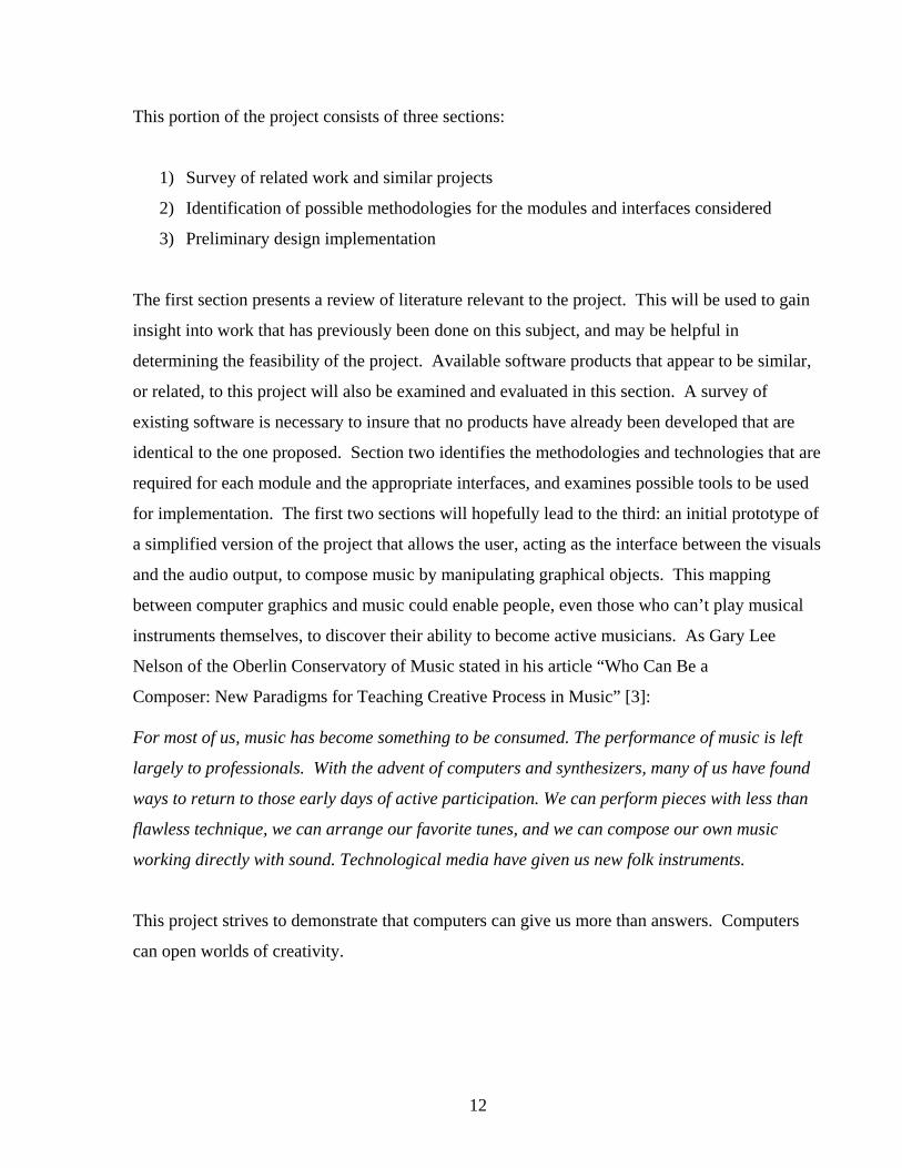
music, but the most relevant to our project is the “musical sketch pads” interface [Figure 15].
The sketch pad allows the user to choose one of four different instruments, each of which is
assigned its own color, and then “draw” the notes in a song for that instrument. After a piece of
music is composed, parts of it may be selected and edited, and the rabbit buttons (see figure 15)
can be used to change the tempo of the piece. The entire composition is played by selecting the
composer button. The commercially available version wasn’t evaluated, but it appears to be very
similar to the online version with some expanded capabilities.
22
Figure 15: Musical Sketch Pad interface of Creating Music software.
3.2.2 Coagula – Industrial Strength Color-Note Organ
Coagula [14] was designed to be an “image synth” – a program to generate sound from images
that can be created and manipulated [Figure 16]. Much like Creating Music, the user has access
to a tool used to draw on the workspace. The image data is read by Coagula, which adds up the
masses of sine waves, and each line in the image controls the amplitude of one oscillator at a
certain pitch. Each pixel represents a single note, with the horizontal position of a specific pixel
in the image corresponding to time, and the pixel’s vertical position determining the frequency of
its pitch. Red and green colors control stereo placement: red is sent to the left channel, while
green controls right channel amplitude. So an orange pixel, with a lot of red and little green,
would have a loud left channel signal and a softer right channel. The loudness of a tone is
mapped to the brightness of the color. A free version of Coagula was evaluated, and even
though everything seemed to load correctly, there were consistently problems with sound
generation.

23
Figure 16: Coagula – Industrial Strength Color-Note Organ 3.2.3 DrawSound
DrawSound was designed as a GUI to CSound, which is a programming language (developed by
Barry Vercoe of MIT) used for the synthesis and processing of sound. DrawSound [15] offers a
paint interface to a musical score, on which the user can enter notes by using drawing tools. Like
Coagula, each pixel represents one note. Each instrument has its own color (six are available),
and the thickness of a line drawn corresponds to the loudness/softness of the notes in that line
[Figure 17]. When the user is finished with a drawing/composition, DrawSound outputs a sound
file (.WAV) and CSound is called to create the sound. The sound file is played back using
mplayer, and a csound interpreter needs to be present to generate the sound file. A free version
of DrawSound was downloaded and the following diagram shows the GUI with a drawing, but I
was never able to get the appropriate interpreter so couldn’t generate sound.
24
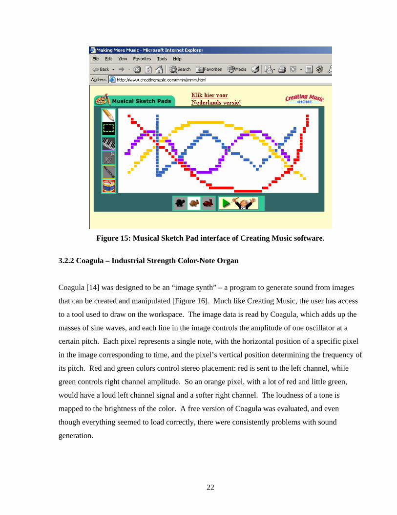
Figure 17: DrawSound GUI
3.2.4 Music Draw 3.2 Designed by John Bunk of BunkCo [16], Music Draw is a music sequencer for people with little
musical knowledge. A Roland GS synthesizer standard is used to present the user with access to
hundreds of realistic sounding instruments. Notes entered for each instrument are layered on top
of each other (15 layers total) [Figure 18]. The user can enter and edit notes for the chosen
instruments in the Music Draw note view. Based upon the key of the music chosen by the user,
and where the notes are placed in the note view, Music Draw chooses a note appropriate to the
key. It’s very easy to change the key of the music, add more instruments, or change the pitch of
a particular note. The downloadable shareware demo version of Music Draw allows the user to
enter 2000 notes before it becomes inoperable, and the full version costs $40.00. This product
worked well and offered more options and instrument choices than most of the software
evaluated.

25
Figure 18: Music Draw 3.2 .
3.2.5 Visual Orchestra (VisOrc) Similar to DrawSound, Visual Orchestra (developed by Dave Perry) [17] is a graphical design
environment [Figure 19] built to utilize CSound. It was designed to offer the user the ability to
build instruments and sounds. It outputs sound in .WAV file format. The link for the free
download version was no longer active; the commercially available version is $75.00.

26
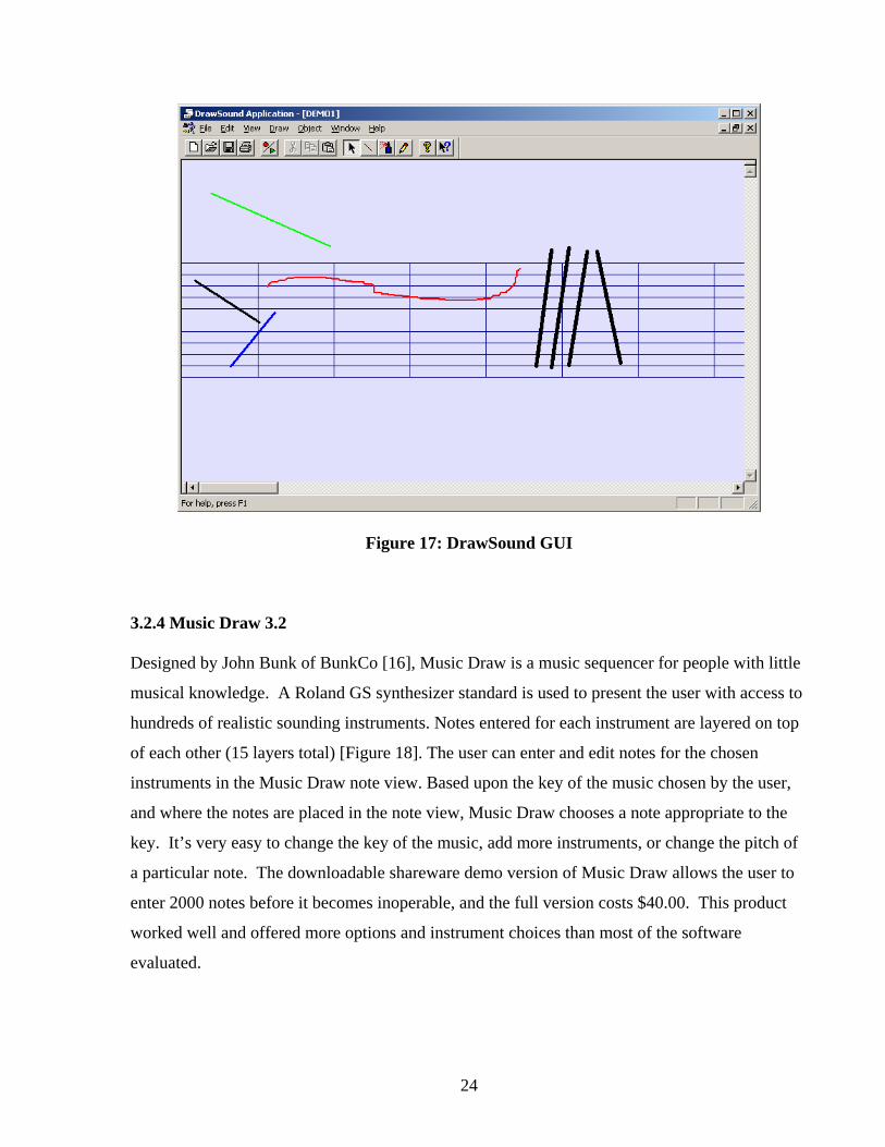
Figure 19: Visual Orchestra 3.2.6 ArtSong
Advertised as an “algorithmic and computer-aided music composition tool designed to help you
compose original music” [18], ArtSong offers a set of musical “building blocks” that are used to
specify musical structures in a different way than the traditional music notation. Compositions
can be saved in standard MIDI format. The commercial version of ArtSong is available for
$59.95. The demo evaluation version (which allows 59 sessions) was downloaded [Figure 20],
and even though the example files that were available were interesting to hear, creating a new
composition seemed like it would require more musical knowledge than most users would have.
27
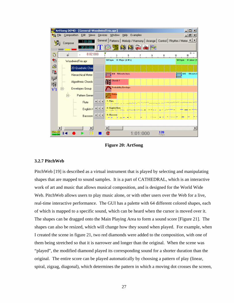
Figure 20: ArtSong 3.2.7 PitchWeb PitchWeb [19] is described as a virtual instrument that is played by selecting and manipulating
shapes that are mapped to sound samples. It is a part of CATHEDRAL, which is an interactive
work of art and music that allows musical composition, and is designed for the World Wide
Web. PitchWeb allows users to play music alone, or with other users over the Web for a live,
real-time interactive performance. The GUI has a palette with 64 different colored shapes, each
of which is mapped to a specific sound, which can be heard when the cursor is moved over it.
The shapes can be dragged onto the Main Playing Area to form a sound score [Figure 21]. The
shapes can also be resized, which will change how they sound when played. For example, when
I created the scene in figure 21, two red diamonds were added to the composition, with one of
them being stretched so that it is narrower and longer than the original. When the scene was
“played”, the modified diamond played its corresponding sound for a shorter duration than the
original. The entire score can be played automatically by choosing a pattern of play (linear,
spiral, zigzag, diagonal), which determines the pattern in which a moving dot crosses the screen,

28
touches the shapes, and generates sounds. PitchWeb was probably the most enjoyable product
evaluated, and had similarities to out project’s concept of physically manipulating shapes to
produce different sounds. The only limitation with PitchWeb is that the shapes can only be re-
sized and deformed slightly, not exactly “sculpted” as our project proposes, and the resulting
change in the sound produced is not considerably different from the original shape’s sound.
Figure 21: PitchWeb
3.2.8 Hyperscore Hyperscore [20] was developed by Mary Farbood and Egon Paszlor of the MIT Media Library.
It is a freely available graphical computer-assisted music composition system that allows the user
to freehand sketch a musical piece, and it claims to be appropriate for users of all musical
backgrounds. It was written in C++ using DirectX. Music is created by working with two types
of musical objects, Motive Windows and Stroke Windows. Melodic material is input into a
Motive Window [Figure 22], where the vertical axis is pitch and the horizontal axis is mapped to

29
time. Colored droplets represent notes, and the droplets can be resized to create longer notes.
Each motive created in a Motive Window is assigned a color that identifies it. An entire piece of
music is composed by using the pen tool to draw with different colors in a Stroke Window. As a
line of a particular color is drawn in the Stroke Window, the motive with that corresponding
color is added to the piece. The length of a line (time element) determines the number of times
that motive is played. Curves in a line change the pitch of the motive. The lines can be edited,
and timbre and harmony control is also available. The music composed with Hyperscore can be
saved as a MIDI file. This product was quite easy to use after reading through a tutorial, and the
idea of creating various musical motives that can be repeated throughout the piece was
interesting, since a song is often composed of themes that are repeated.
Figure 22: HyperScore

30
All of the products evaluated have aspects that are similar to parts of our proposed project, since
all use a mapping between graphical elements and musical output as a computer-aided music
composition tool. A number of them have notable elements that may be useful to consider when
implementing this project:
• The ease with which Music Draw 3.2 allows the user to add instruments, and
change the key, mood, or the pitch of a note, may apply to the function of the music AI
engine in our project.
• PitchWeb has the most interesting method of assigning sound to a palette of
graphical objects and allowing the user to place them on the scene and
manipulate them to create a composition.
• HyperScore’s view of the song as a composition of repeated motives that the
user defines may be helpful when designing the way the project deals with the
form of the song composed.
• The ease of use and appearance of the GUI’s, especially those found in
Creating Music, PitchWeb, and HyperScore, reinforced our goal to design a
user-interface that is not only functional and simple to use, but one that adds to
the visual experience of the environment.
• The fact that all of the software reviewed utilizes MIDI for the sound portion
of the design seems to suggest that our initial inclination to investigate
MIDI technology for this project is appropriate.
Although the products found have similarities to the proposed project, it seems that none of them
exactly mirror this project’s concept. In light of this finding, design and implementation of the
project were initiated.
31
4. Methodologies and Implementation This section of the project involved identifying the technologies appropriate for implementing
the various modules and interfaces of the design. This paper will present the steps taken toward
implementation, the issues encountered, and the ways in which the problems confronted led to
new avenues of investigation.
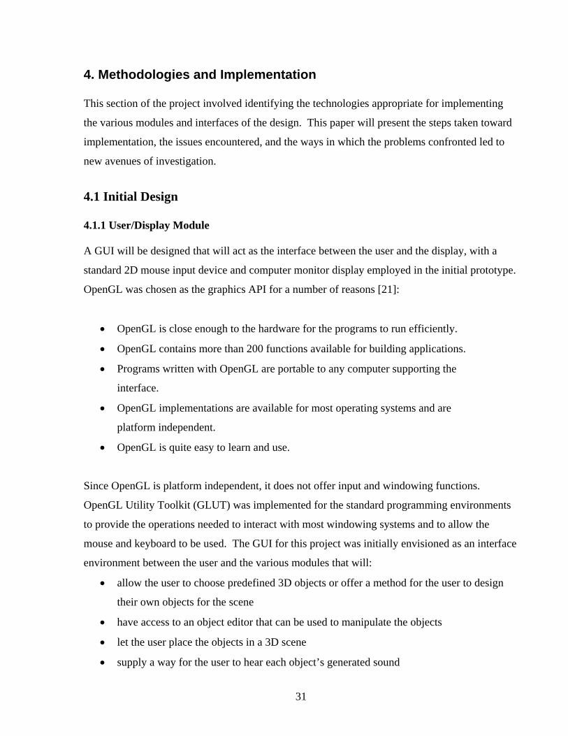
4.1 Initial Design 4.1.1 User/Display Module A GUI will be designed that will act as the interface between the user and the display, with a
standard 2D mouse input device and computer monitor display employed in the initial prototype.
OpenGL was chosen as the graphics API for a number of reasons [21]:
• OpenGL is close enough to the hardware for the programs to run efficiently.
• OpenGL contains more than 200 functions available for building applications.
• Programs written with OpenGL are portable to any computer supporting the
interface.
• OpenGL implementations are available for most operating systems and are
platform independent.
• OpenGL is quite easy to learn and use.
Since OpenGL is platform independent, it does not offer input and windowing functions.
OpenGL Utility Toolkit (GLUT) was implemented for the standard programming environments
to provide the operations needed to interact with most windowing systems and to allow the
mouse and keyboard to be used. The GUI for this project was initially envisioned as an interface
environment between the user and the various modules that will:
• allow the user to choose predefined 3D objects or offer a method for the user to design
their own objects for the scene
• have access to an object editor that can be used to manipulate the objects
• let the user place the objects in a 3D scene
• supply a way for the user to hear each object’s generated sound

32
• play back the “song” created through the building of the entire 3D scene
• save the scene and resulting musical composition to a file that can be retrieved and
loaded into the application later
A variety of widgets will be used in the GUI to allow the user to easily interact with the
application. Since GLUT was designed to be simple and portable, it provides only one important
widget: menus that are usually implemented to pop-up when a mouse button is held down. It
was necessary to find an application that would offer an extended set of widgets that could be
used to build a GUI, but that would still work with OpenGL. Two options were found:
(1) Picoscopic User Interface (PUI) [22] – designed by Steve Baker to be used to
design GUI’s for simple portable 3D games in OpenGL. Freely available [22],
PUI offers a set of simple widgets that allow the designer to build a customizable
GUI that overlays an OpenGL program.
(2) GLUI [23] - this free, GLUT-based C++ user interface library was designed by
Paul Rademacher to provide controls such as buttons, checkboxes, radio buttons,
and spinners to OpenGL applications. GLUI offers support for multiple user
interface windows, while PUI was designed for simpler applications. GLUI is
window-system independent, and it relies on GLUT to handle mouse and
window management. Figure 23 is a screenshot of a GLUI window that shows
the different widgets available, and figure 24 shows a GLUI window with a
subwindow docked within the main window.

33
Figure 23: GLUI window showing available widgets [23]
Figure 24: GLUI window with subwindow [23]
It appears that GLUI may be more appropriate for this project due to its support for multiple user
interface windows, but both applications were downloaded and will be considered for project
implementation.

34
4.1.2 Graphics Module
The graphics module will be responsible for the creation and manipulation of the 3D objects the
user chooses to place in the scene. The project concept visualized the objects as soft-body 3D
shapes that could be “sculpted”, or deformed, like clay. Deformation, by definition, involves
altering the shape of an object by pressure or stress. Free Form Deformation (FFD) is one of the
techniques that have been used to deform computer-generated objects. Instead of manipulating
the object directly, FFD is usually accomplished by first defining a cubic shaped lattice of
control points around the object, and then manipulating the control points to change the shape of
the lattice. As the lattice is deformed, the object inside the lattice is also deformed [Figure 25].
Figure 25: Free Form Deformation of a 3D object
using lattice control points [24]
Another method sometimes used to accomplish FFD is to directly manipulate the vertices of the
object, but this is not successful unless the object has enough vertices to allow smooth
deformation and to prevent distortion. OpenGL doesn’t offer any built-in functions for object
deformation, so using FFD in this project would involve writing an OpenGL program
implementing the technique - very likely a semester of work in itself. It was decided that the
work on the initial prototype of the product wouldn’t include implementing an object
deformation program from scratch, though this task may be undertaken at a future date, so
various 3D modeling software products were evaluated to locate an application that performed
FFD and could be integrated into the project. The primary characteristics that were considered in
the product review were:
• Ease of use – creation and manipulation of the objects should be intuitive or
simple to learn

35
• Object deformation should model “sculpting” as closely as possible
• Application needs to allow export of a file format that can be integrated into an
OpenGL program
• Cost
Three software products were evaluated: Blender, 3D Canvas, and Amorphium.
Blender [25]
Blender is a 3D graphics creation suite that is freely downloadable. The user interface [Figure
26] offers multiple features for object creation and manipulation, but I found it somewhat
overwhelming and believe that it would take an extensive amount of time and practice to become
comfortable with using it. Object deformation is accomplished with FFD of a surrounding lattice
[Figure 27]. Blender has the capability to export 3D images in Open Inventor (an object-oriented
3D toolkit designed by SGI), DXF (a file format created by AutoDesk to represent 3D models
and scenes built with autoCAD), and VRML (Virtual Reality Modeling Language) [26].
Figure 26: Blender user interface

36
Figure 27: Blender object deformation
3D Canvas [27]
The user interface of 3D Canvas [Figure 28] seemed much easier to understand and navigate
than Blender, and after going through a number of available tutorials, creation and manipulation
of objects was fairly straightforward. Object control points are manipulated to deform the object
[Figure 29]. A fully functional version is available as freeware, and 3D Canvas Plus and Pro
versions can be purchased for $34.95 and $69.95. The export file formats of 3D images for the
freeware version are very limited, and the Pro version affords the most extensive export
capability, including DXF and VRML. Even though 3D Canvas was easier to use than Blender,
problems were intermittently encountered – the program would sometimes generate an
unrecoverable error and would exit, but the application would continue running in the
background and would have to be terminated through the task manager. Attempts to correct this
problem were unsuccessful.

37
Figure 28: 3D Canvas user interface
Figure 29: 3D Canvas object deformation
38
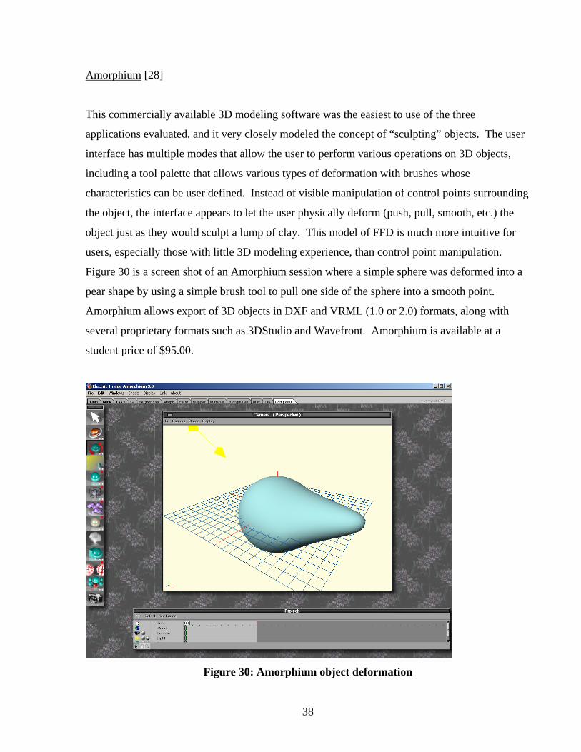
Amorphium [28]
This commercially available 3D modeling software was the easiest to use of the three
applications evaluated, and it very closely modeled the concept of “sculpting” objects. The user
interface has multiple modes that allow the user to perform various operations on 3D objects,
including a tool palette that allows various types of deformation with brushes whose
characteristics can be user defined. Instead of visible manipulation of control points surrounding
the object, the interface appears to let the user physically deform (push, pull, smooth, etc.) the
object just as they would sculpt a lump of clay. This model of FFD is much more intuitive for
users, especially those with little 3D modeling experience, than control point manipulation.
Figure 30 is a screen shot of an Amorphium session where a simple sphere was deformed into a
pear shape by using a simple brush tool to pull one side of the sphere into a smooth point.
Amorphium allows export of 3D objects in DXF and VRML (1.0 or 2.0) formats, along with
several proprietary formats such as 3DStudio and Wavefront. Amorphium is available at a
student price of $95.00.
Figure 30: Amorphium object deformation

39
After evaluation of the three applications, we decided to purchase and attempt to integrate
Amorphium into the project, primarily because of the way it so closely matched our vision of
how we wanted the user to be able to manipulate objects.
4.1.3 Sound Synthesis Module
As with object deformation, OpenGL doesn’t offer built-in functions for sound synthesis, so
some type of virtual synthesizer will be needed to create the sounds mapped to the objects
created by the user. Before looking at synthesizers that could be utilized, synthesizer
architecture and operation were examined. The main modules of software synthesizers and their
functions are [29, 30]:
Oscillator
The main sound source of a synthesizer. Pulsing electrical signals are output as a
waveform, which can be in various shapes such as sine, triangle (sawtooth), or square
[Figure 31]. The frequency of the pulses determines the pitch of the sound. The shape of
the wave can help emulate sounds with different timbres since the shape of the wave
determines the harmonic makeup, the quality, of the sound.
Figure 31: Oscillator waveforms
Filter
Most synthesizers have filters that allow the basic waveforms output by the oscillator to
be edited and shaped. A filter is used to increase or decrease specific frequency regions
of the wave to change the sound.

40
Amplifier
The sound signal in a synthesizer passes through the amplifier circuit to control the
volume. The amplifier raises or lowers the height of the waveform produced by the
oscillator to raise or lower the volume.
ADSR Envelope Generator
The Attack Decay Sustain Release (ADSR) envelope is used to model natural sounds in a
synthesizer – most sounds don’t simply switch on and off and are usually not static, the
characteristics of the sound change over time. This change in behavior of the sound is
called its envelope. The envelope generator controls the four main parameters of the
envelope [Figure 32]:
• Attack: the initial onset of the sound, the time it takes for the sound
to reach its loudest point.
• Decay: begins immediately after the attack, the time it takes for the
sound to reach the sustain level.
• Sustain: the level that the sound settles down to for most of its
duration.
• Release: the fade out of the sound, the time taken for the sound to
fade away.
Figure 32: ADSR envelope
Low Frequency Oscillator (LFO)
This oscillator is used to manipulate sound below the audible frequency range and is
typically used to modulate sounds to create vibrato, tremolo, and trills.
41
Most modern synthesizers are multi-timbral (poly-phonic), which means that they can play
several different sounds at once. To achieve this, more oscillators, filters, and amplifiers are
added to create more voices that can be played at the same time. In this way, the synthesizer
becomes capable of playing the multiple parts found in a musical piece.
Two virtual synthesizers available as freeware or in a downloadable demo version were
evaluated: SubSynth and SawCutter.
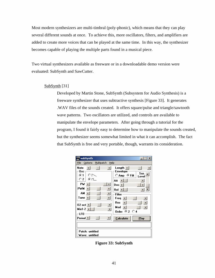
SubSynth [31]
Developed by Martin Stone, SubSynth (Subsystem for Audio Synthesis) is a
freeware synthesizer that uses subtractive synthesis [Figure 33]. It generates
.WAV files of the sounds created. It offers square/pulse and triangle/sawtooth
wave patterns. Two oscillators are utilized, and controls are available to
manipulate the envelope parameters. After going through a tutorial for the
program, I found it fairly easy to determine how to manipulate the sounds created,
but the synthesizer seems somewhat limited in what it can accomplish. The fact
that SubSynth is free and very portable, though, warrants its consideration.
Figure 33: SubSynth

42
SawCutter [32]
This synthesizer [Figure 34] allows the user to hand draw waveforms and envelopes. As
many as four instruments can be used at a time, and there is a choice of eight waveforms
and eight sets of envelopes for each instrument. A demo version is available to
download, and the commercial version costs $24.95. I found SawCutter to be easier to
use than SubSynth, and the controls all seem to be very intuitive, especially the manner in
which the envelopes and waveforms can be hand drawn and controlled.
Figure 34: SawCutter
No decisions were made at this point as to which virtual synthesizer would be used for sound
synthesis for the project, but evaluation of these two products offered insight into the technology
available for this module. The manner in which the synthesizer used would be interfaced with
the OpenGL program for the project will also need to be determined at a future point.
43
4.1.4 Mapping Module
The graphics module will allow the user to create and manipulate 3D objects that will form a
scene that the mapping module will accept as input. The ultimate function of the mapping
module is to use characteristics of the created scene to produce as output music control
parameters that can be used by the sound synthesis module to generate music. This module is
the most complicated of this portion of the project, since it is responsible for not only
determining the mapping process to be used, but also for dealing with the necessary interfaces
between the graphics and sound synthesis modules and itself. Possible schemes for interfacing
the modules will be presented first, followed by a discussion of the mapping strategies
considered.
4.1.4.1 Graphics Module/Mapping Module Interface
At this point in the project, Amorphium has been chosen as a 3D modeling application to use to
create and manipulate the objects that serve as the input to the mapping module. As mentioned
previously, Amorphium allows the user to save the objects created in DXF or VRML 1.0 or 2.0
file formats. What is ultimately necessary in order for the mapping module (written in OpenGL)
to transform 3D objects into parameters that an OpenGL program and the sound synthesis
module can use is a way in which the information stored in the file format of an Amorphium
object can be retrieved and utilized. Both DXF and VRML save to text files, so both can be
created and read with a simple text editor. This characteristic may make it possible for an
OpenGL program to parse the file and retrieve the parameters needed. In choosing between
DXF and VRML formats, it was discovered that DXF appears to support only two 3D types,
3DFACE (which specifies 3 – 4 vertex facets) and 3DLINE (specifies two endpoints). VRML,
on the other hand, was designed to be a common file format that can be used to describe and
view 3D objects and worlds, so it supports many more 3D types, such as spheres. Because of
this, it was decided to use VRML as the file format to save Amorphium objects in. VRML
specifications were examined to gain a rudimentary knowledge of how a VRML file is laid out,
and Amorphium objects were saved in VRML format so that the generated text file could be
examined. It was discovered that although VRML files are fairly easy to understand, when 3D

44
objects are saved in VRML the sheer number of vertices generated for one object produces a
huge text file. Although it would still be possible to write a program that would parse the VRML
file and retrieve parameters that could be used by an OpenGL program, finding a VRML ->
OpenGL converter that has already been implemented seemed preferable to writing a new one.
Two such programs were located:
(1) Vrml2OGL [33] – designed by Alexander Rohra and available as
freeware, this converter generates three output files from a VRML
file:
(a) an OpenGL file with object drawing code in a C-callable
function
(b) a header file containing the function prototype for the object
drawing function contained in the OpenGL C file, and a few
#define statements and external variable definitions
(c) a data file containing matrix as well as material and color arrays
which are made public by the header file.
The only problem that this converter may have is that it appears that
VRML sphere nodes may not be supported, and sphere primitives
will likely be needed for the project.
(2) VRML2GL [34] – also available as freeware and written by Leigh
McRae for Now Enterprises, this parser takes VRML 1.0 files and
converts them to OpenGL format. It appears that most VRML node
types are supported, so this converter was downloaded and will be
tested on an Amorphium VRML 1.0 file.
4.1.4.2 Mapping Module/Sound Synthesis Module Interface
The mapping module will need to input the object parameters it retrieves from the graphics
module into the sound synthesis module so that sound can be output. As mentioned previously,
OpenGL does not have direct sound support, so a method needed to be found that would allow
45
the program to interact in some way with the sound source chosen for the project. In looking for
sample OpenGL programs that integrated sound, it was discovered that most utilize DirectX for
sound capabilities [35]. DirectX is a suite of multimedia API’s that are built into Windows, and it
includes the DirectX Audio API. DirectX allows a program to load and play sounds from files in
MIDI and WAV formats, play from multiple sources simultaneously, and capture MIDI data.
Using the DirectX Audio API for this project would require learning enough DirectX
programming to facilitate writing an OpenGL application that would allow the mapping and
sound synthesis modules to communicate and output sound.
Another API that is sometimes used with OpenGL to integrate sound is OpenAL (Open Audio
Library). OpenAL is a cross-platform 3D audio API used in gaming and other 3D applications
that require sound [36]. Several tutorials were found that combine OpenAL and OpenGL, but as
with DirectX, using this API would involve learning the API specifications and usage.
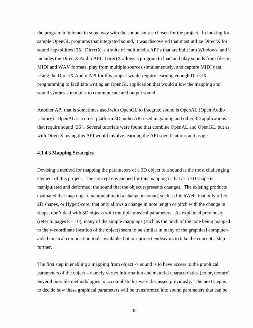
4.1.4.3 Mapping Strategies
Devising a method for mapping the parameters of a 3D object to a sound is the most challenging
element of this project. The concept envisioned for this mapping is that as a 3D shape is
manipulated and deformed, the sound that the object represents changes. The existing products
evaluated that map object manipulation to a change in sound, such as PitchWeb, that only offers
2D shapes, or HyperScore, that only allows a change in note length or pitch with the change in
shape, don’t deal with 3D objects with multiple musical parameters. As explained previously
(refer to pages 8 – 10), many of the simple mappings (such as the pitch of the note being mapped
to the y-coordinate location of the object) seem to be similar in many of the graphical computer-
aided musical composition tools available, but our project endeavors to take the concept a step
further.
The first step in enabling a mapping from object -> sound is to have access to the graphical
parameters of the object – namely vertex information and material characteristics (color, texture).
Several possible methodologies to accomplish this were discussed previously. The next step is
to decide how these graphical parameters will be transformed into sound parameters that can be

46
fed into a synthesizer. At this time, the mapping strategy explored that makes the most sense and
may be the most feasible is to map the object parameters to the ADSR envelope parameters used
by a synthesizer (refer to page 40). The shape (probably the silhouette) of the object could be
seen as a representation of the envelope’s shape, and the attack, decay, sustain and release values
would be obtained from the object’s coordinates. As an example, figure 35 shows the pear shape
in the Amorphium screenshot displayed earlier [Figure 30] overlaid with a representation of an
ADSR envelope to demonstrate a possible mapping. As the shape of the object changes, the
shape of the envelope changes, and the sound changes.
Figure 35: Mapping object parameters to an ADSR envelope

47
4.2 Squeak [37] At this point in the determination of methodologies to be used for the project, the techniques and
applications discussed in the initial design portion of this paper had been identified as possible
tools to facilitate actual implementation. Although in theory the methodologies and interfaces
proposed for the design of the initial prototype appeared feasible to implement, in reality the
question is always “will it all successfully work together the way it’s designed to?” As the
process of putting all of the pieces together and building the project was to begin, I came across
several references to a programming language called Squeak being used to build multimedia
applications. Discovery of this implementation of the Smalltalk-80 language opened up an
entirely new avenue of research and design strategy for this project. At first glance, Squeak
seemed to offer an environment that could be suitable for creating the entire application as a
single integrated project without having to deal with interface issues between modules. Since
this would go a long way towards answering the question stated above, the decision was made to
investigate Squeak and determine if it represents an appropriate design environment for the
project. In the following sections, an overview of Squeak will be presented, along with a
discussion of how Squeak could be used in the development of the various modules of the
project.
4.2.1 The Squeak Language and Environment [38]
The Smalltalk programming language, designed in the early 1970’s at Xerox’s Palo Alto
Research Center, was the first language that was object-oriented as we think of OO programming
today. Smalltalk systems were the first to have overlapping windows, menus, icons, and a
mouse pointing device. Several versions of Smalltalk evolved over the years, including
Smalltalk-80, which was released to a number of different computer companies as a test of
Smalltalk’s portability. Portability was achieved by implementing Smalltalk-80 as a bytecode
compiler – instead of compiling the code into machine language native to the computer it is
running on, the code was compiled into a machine language for a virtual machine (VM). An
interpreter in the computer’s native machine language then executed the VM bytecode.

48
In 1995, a group at Apple Computer (Alan Kay, Dan Ingalls, and Ted Kaehler) became
interested in designing “a development environment in which to build educational software that
could be used – and even programmed – by non-technical people, and by children. [38]” They
wanted to use Smalltalk, but the available commercial version of Smalltalk-80 didn’t have some
of the flexibility and features they were looking for, plus they wished to make their application
open-source. The Squeak programming language was born when they decided to build a
Smalltalk-80 implementation that fit their specifications. Everything in Squeak was written in
Smalltalk, including the VM. A Smalltalk-to-C translator was written to translate the Smalltalk
VM to C code. This C code was then compiled to create a native machine executable. The
image could then be run from this executable, and nearly everything in Squeak could
subsequently be written directly in Squeak. As stated in the paper that introduced Squeak [39]:
Squeak stands alone as a practical Smalltalk in which a researcher, professor, or motivated
student can examine source code for every part of the system, including graphics primitives and
the virtual machine itself, and make changes immediately and without needing to see or deal
with any language other than Smalltalk.
Squeak was released to the Internet in September 1996 [40]. Even though the Squeak team is
now at Disney Imagineering Research and Development, Apple’s Squeak license allows users
the freedom to freely create with Squeak. Its open-source nature has led to many enhancements
to the language, including support for 2D and 3D color graphics, multi-voiced sampled and
synthesized sounds, animation and video capability, and the ability to handle most of the major
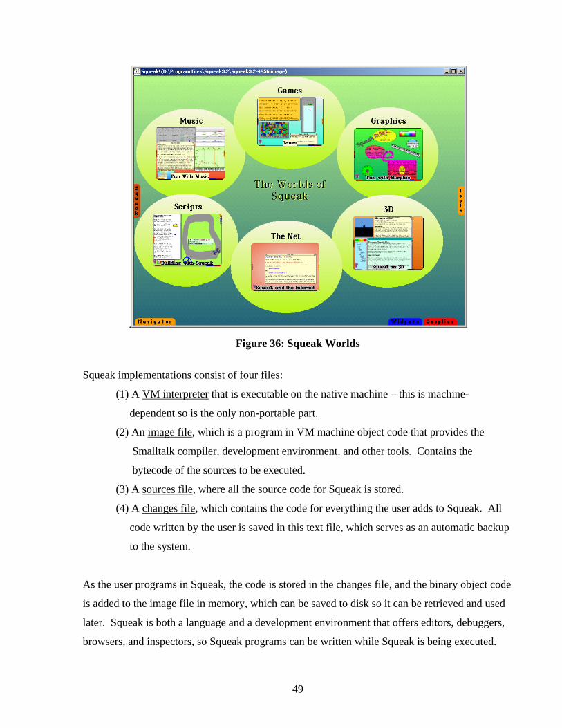
media formats. Figure 36 shows the Squeak screen that is the portal into the different Squeak
worlds available.
49
.
Figure 36: Squeak Worlds
Squeak implementations consist of four files:
(1) A VM interpreter that is executable on the native machine – this is machine-
dependent so is the only non-portable part.
(2) An image file, which is a program in VM machine object code that provides the
Smalltalk compiler, development environment, and other tools. Contains the
bytecode of the sources to be executed.
(3) A sources file, where all the source code for Squeak is stored.
(4) A changes file, which contains the code for everything the user adds to Squeak. All
code written by the user is saved in this text file, which serves as an automatic backup
to the system.
As the user programs in Squeak, the code is stored in the changes file, and the binary object code
is added to the image file in memory, which can be saved to disk so it can be retrieved and used
later. Squeak is both a language and a development environment that offers editors, debuggers,
browsers, and inspectors, so Squeak programs can be written while Squeak is being executed.

50
Figure 37 is a Squeak screenshot showing several of the workspace tools available in the
environment. The System Browser gives a listing, plus the code, for all of the Squeak and
Smalltalk classes available and their methods, and serves as a workspace where new classes and
methods can be defined by the user. The Workspace acts as a text editor where code can be
typed and executed. The Transcript is the area where output is printed to the screen. The File
List gives the user access to all files on the local computer.
Figure 37: Squeak workspace tools
The tabs along the bottom and sides of the Squeak screen afford the user access to various other
tools, most of which can be chosen and dragged onto the screen directly. The Navigator includes
controls needed to navigate through projects – multiple projects can be developed simultaneously
in the environment. The Widget tab has controls and media tools such as a movie player and a

51
device for sound recording. Many basic types of objects, like shapes and buttons, can be found
under the Supplies tab. The Tools tab gives access to all of the system workspace tools, such as
the Transcript, Workspace, and System Browser environments.
Squeak offers two different user interface (UI) environments to work within: MVC (Model-
View-Controller) and Morphic. MVC is a direct descendent of the original Smalltalk-80 MVC
and was the original UI environment in Squeak. In MVC the user interface is described in terms
of a model of the real world, which is presented in a view, with one or more controllers handling
user input, such as mouse and keyboard inputs, and commanding the model and/or view to
change as needed. Morphic was developed by John Maloney and Randy Smith as part of the
Self language environment project at Sun Microsystems Labs. Maloney brought Morphic with
him when he left the Sun project and joined Apple as Squeak was being created. Every object in
Morphic, including windows, menus, and widgets, is a Morph, which is the key design element
in the environment. Morphic objects inherit a set of standard behaviors and interfaces and have
three characteristics:
(1) Morphs are concrete – they can be moved around and manipulated just as real-world
objects can.
(2) All Morph objects are uniform – they all have a basic structure and can be
manipulated in the same basic ways, which is accomplished by accessing a halo
around every Morph that gives object editing and manipulation options [Figure 38].
Figure 38: Morphic object halo
(3) Morph objects are flexible, they can be manipulated freely.
52
Many Morphs are built into Squeak and can be dragged and dropped into the Morphic world,
plus Morphs can be user-defined, so user interfaces can be easily designed and assembled within
the Morphic environment.
One of the primary goals of Morphic was to make it easy to construct and edit interactive
graphical objects, which can be accomplished in two different ways: by direct manipulation
(user-scripting) and from within programs. In classic Morphic programming, the user defines
subclasses of the available Morph classes, in effect extending the Morphic system by creating
and modifying classes in the Squeak Smalltalk browser. In user-scripting style, Morphs are
created by directly assembling standard Morphic parts then giving them special states and
behaviors by associating them with “Players”, the fundamental object types in user-scripting,
and defining instance variables and methods for the Players. An analogy used to explain the
relationship between user-scripted Morphs and Players is that every Morph has an associated
Player as its "costumee", and every Player has an associated Morph that it "wears" as its
"costume"[41].
One of the halo options around every Morph is a Viewer button – this brings up a dynamic
graphical Inspector and Browser that can be used to view and change object properties, view and
invoke object scripts, and add instance variables and methods to the object. Figure 39 is a
screenshot of a Morphic world where a star Morph and its associated Viewer with several of the
available property fields for the object, here the scripts, basic, and color and border fields are
displayed. The properties in each field can be directly manipulated by changing the values with
the arrows, and then commands can be sent to the object by clicking on the yellow exclamation
points. Writing scripts for the object involves assembling a sequence of commands in a
“Scriptor”, such as the single script that has been dragged next to the star in figure 39 and has the
property for the object’s sound. Additional properties can be added to, and defined for, this
script, so that when the script is subsequently called, all of the actions in the script would be
performed in sequence.

53
The flexibility that Morphic offers with the choice of either classic programming or user-
scripting allows the user to easily create and construct interactive graphical objects and user
interfaces. The remaining discussion of Squeak will be restricted to the Morphic environment.
Figure 39: Morphic user-scripting
4.2.2 Squeak Graphics Squeak offers a wide range of graphics tools, including extensive text support, painting tools,
and 3D capabilities. The 3D rendering engine for Squeak is called Balloon3D, developed by
Andreas Raab. Balloon 3D provides the necessary primitives, such as lighting, shading,
texturing, mesh and matrix transformations, that are needed to create a 3D scene. There are
many classes and methods within Squeak that have been defined for Balloon3D that allow the
user to create and manipulate 3D objects. Another means of creating 3D worlds within Squeak
was developed by Jeff Pierce. He took Alice, a 3D scripting environment that had previously
been designed (at Carnegie Mellon University) to allow people without programming experience

54
to build interactive 3D worlds, and developed Wonderland in Squeak, which is essentially Alice
on top of Balloon. This system organizes the objects in the 3D world into a scene graph, which
is a hierarchical structure used to describe the relationship between the objects in the scene and
their properties. Wonderlands are interactive 3D worlds within Squeak that give the user access
to a script editor, a control panel, and a window into the 3D world. Wonderland can load in
several 3D file formats, including Alice format (.mdl) and VRML files. There are hundreds of
3D objects in the .mdl format that are freely available. After 3D objects are loaded into or
designed within a Wonderland, scripts can be written to manipulate the objects in many ways.
For this project, several methods found within Squeak graphics could be used to design the
graphics module:
B3DMorph is the basic class for 3D Morphic objects within Balloon3D, and examination
of this class and its methods will offer insight into how 3D objects within Squeak can be
created and manipulated through basic programming.
The halo around a Wonderland world has an icon called “Pooh” that allows the user to
freeform draw a 2D object that is automatically transformed into a 3D object. Objects
created this way can then be edited with their own halo.
VRML objects created with Amorphium (refer to page 38), or 3D objects available in the
Alice format, could be loaded into and used within a Wonderland.
Figure 40 is a screenshot of a Squeak Morphic project that has two Wonderlands open and
demonstrates several of the 3D object creation methods above. In the left Wonderland, a sphere
object in the Alice file format was imported. A Pooh 2D teardrop shape was drawn in the
Wonderland on the right, and was automatically transformed into a 3D shape that was painted
with its halo options. Also visible are the script editor and the control panel that shows the
hierarchical scene graph structure of the Wonderland on the right.

55
Figure 40: Creating 3D objects in Squeak with Wonderland
A few issues were encountered when researching the ways that the graphics module in this
project could be implemented within Squeak. It was not immediately obvious if the Balloon3D
classes include methods to accomplish free form deformation of objects (but it seems they
probably don’t), and further experience with Smalltalk programming would be necessary to
determine if FFD could be accomplished within Squeak. For the initial prototype, it may be
necessary to design a set of 3D objects that the user can choose from to create the scene, with a
real-time object editor being implemented during future development. The Pooh halo option
offers an interesting way to create freeform 3D objects, but it appears to be supported in Squeak
versions up to 3.2, but not in the most recent version, 3.6. Attempts to discover why this object
creation method has been dropped have been unsuccessful. If the Pooh drawing method is
considered for the project, a full comparison of versions 3.2 and 3.6 would be necessary to
determine if the older version would be appropriate for implementation, or if the recent version
could be modified to include this capability. Experimentation with the various ways 3D objects

56
can be handled in Squeak will be needed to determine which is the most appropriate for the
project.
4.2.3 Squeak Sound
Squeak offers extensive sound support, including the ability to play instrumental music stored as
MIDI files, generate synthesized sounds with Squeak's built-in FM synthesis algorithm, and edit
sound by directly manipulating the ADSR envelopes (refer to page 40) with Squeak’s FM Sound
Editor. The main Squeak sound class is AbstractSound, which uses a sound model that views all
sound as consisting of a set of samples. Graphically, these samples are periodic waves with
values that alternate between positive and negative. The sound envelopes can be used as filters
to shape the samples in real-time to create different effects. Squeak has a built-in collection of
synthesized instruments, and user-created instruments can be defined. A number of sound tools
that could be used to implement the sound module in this project are provided in Squeak:
• MIDI Score Player – has tools for playing a MIDI file, along with a visual representation
of the tracks in the piece and the instrument in each track. The instruments in a piece can
easily be changed, and the Score Player allows instruments to be edited by bringing up an
Envelope Editor.
• Piano Roll – this is a representation of the MIDI score that shows each track as a separate
color and each note as a line segment, where the vertical position indicates pitch and
length indicates note duration. A song can be manipulated with the Piano Roll by
copying and pasting notes into the field, or by using the available keyboard to insert new
notes into the score.
• Envelope Editor – Squeak offers ADSR envelopes that can be used to modify the volume
or pitch as sound is being generated by manually manipulating the envelope graph (the
envelopes are actually ASD (Attack Sustain Decay), but are very similar to the ADSR
envelopes presented previously). A keyboard is attached to the Envelope Editor window
so that sounds can be tested as they are edited.
Clockwise from the upper left, figure 41 shows the Squeak Score Player, Piano Roll, keyboard,
and Envelope Editor.

57
Figure 41: Squeak Sound Tools
Taking advantage of the sound support in Squeak would involve becoming adept at using the
Smalltalk sound classes, since classic Smalltalk programming is necessary to access and
manipulate most of the sound parameters and capabilities.
4.2.4 Mapping Module and Squeak
Since all of the modules needed in this portion of the project have corresponding modules within
Squeak, the challenge of interfacing the modules appears to become much simpler if Squeak
were to be used as the design environment. Instead of having separate modules trying to work
together, Squeak implementation would involve a single integrated project. All of the graphics
and sound classes are simply a part of the Smalltalk class library, so module interface would just
be a matter of manipulating and adding to the class methods already available. It appears that
there are a number of methods already defined in Squeak that would be needed to accomplish the
object -> sound mapping process, including functions that return the parameters, such as vertices,

58
of objects. Although Squeak appears to be a very appropriate language and environment for this
project, extensive research and experimentation with Smalltalk programming and Squeak usage
would be necessary for successful implementation. It was decided at this point to attempt to
develop a limited prototype of the project in the Squeak environment in order to determine the
feasibility of a Squeak implementation, and to provide a tangible model of our vision of the
project.
4.2.5 Squeak Prototype
A completely functional Squeak implementation will require a more extensive knowledge of
Smalltalk programming than time allows for this portion of the project, so a simplified prototype
that demonstrates Squeak’s features and shows an example of the project’s possible appearance
was created. Figure 42 shows a screenshot of the prototype, and the individual elements are
discussed in the following sections.
Figure 42: Squeak Prototype

59
4.2.5.1 Object Editor Window [Figure 43]
This is a Wonderland world (refer to pages 53 – 54) where the user can create and manipulate 3D
objects to be used in the scene. The prototype utilizes the Pooh halo option to create 3D objects
(refer to page 54), which can then be edited with paint, stretch, squash, shrink, and grow options
that are inherent to all Wonderland objects. More experimentation with Squeak will be
necessary before a final decision is made as to which technique will be used to create 3D objects:
the Wonderland Alice methods, or the 3D capabilities in Balloon3D. The elliptical buttons on
the left each play a short sample of a different synthesized musical instrument available in
Squeak, with a balloon that pops up (when the mouse passes over it) and identifies the
instrument name. Although not functional at this time, it is envisioned that when the user
chooses an instrument button, the object will be painted that instrument’s corresponding color,
the envelope editor displayed to the right of the object editor window will be open to that
instrument’s envelopes, and the shape of the object will be mapped to the envelope’s shape. In
this example, the user has chosen the pink button, which corresponds to a clarinet instrument,
and the object has been painted accordingly. The resulting sound created through this mapping
will be assigned to the object as its sound, which can be heard by clicking on the object itself.
The user will then be able to save this object and its sound to be used later, or delete the object
completely, with the save and delete buttons. The user will be able to drag the objects created in
this window into the scene composition window at the bottom of the screen to create a
composition.
Figure 43: Object Editor Window

60
4.2.5.2 Envelope Editor Window [Figure 44] This Squeak provided morph will probably not be displayed in the implementation offered to
users since one of the goals of the project is to allow people with limited music and computer
knowledge to easily create compositions, and most users will not know how the ADSR
envelopes function (refer to page 40). It was included in this prototype to demonstrate the
mapping between the object created and the sound envelopes. In this example, the user has
chosen to make the object sound like a clarinet, so the envelope editor is opened on the clarinet
(Timbre: clarinet) and its envelopes. The object’s shape will be mapped to one of the clarinet’s
envelopes (volume here), and the resulting new sound will be assigned to that object. The
mapping has not been implemented in this prototype, but is simulated by manually manipulating
the shape of the volume envelope to resemble the silhouette of the object. A keyboard morph is
attached to the envelope editor morph so that the user can hear (by playing any of the keys) how
the changes made to the envelope affect the sound of the instrument. Even though the envelope
editor morph will probably be working behind the scenes in the final implementation, it may be
useful to display a keyboard associated with the object editor window that gives the user the
ability to hear immediate feedback on how the changes they make to the shape of an object affect
its corresponding sound.
Figure 44: Envelope Editor Window

61
4.2.5.3 Scene Composition Window [Figure 45] In the completely functional implementation, the user will be able to duplicate, drag, and drop
objects created in the object editor window into the scene composition window in order to create
an entire 3D scene that represents a musical composition. Once the objects are placed into the
scene, the user will have the ability to choose an object, hear its sound, and possibly re-open the
object in the object editor window if further editing is required. In this prototype, a second
Wonderland is used to build the scene. Since no methods are currently available in Squeak to
maintain objects across multiple Wonderlands, the objects in this scene were actually created and
manipulated within the second Wonderland, not in the object editor window. This example
shows a scene in which objects representing three different instruments (purple, yellow, pink)
have been created, manipulated, and placed into the composition. As explained earlier in this
paper (refer to pages 8 – 10), an object’s size and location will determine its pitch, volume, and
duration. A pink scan line morph at the left of the window will move across the scene as the
composition is played so that the user can visually see which objects are sounding at any point in
the music. The stop, step, and go buttons control the scan line, and the reset button moves the
scan line back to the beginning of the scene/composition. The record button will allow the user
to save the entire composition for later playback, possibly as a MIDI score. The functionality of
the scene composition window in this prototype is very limited since a large portion of the
Smalltalk programming necessary to produce a finished product will involve this window, but
the prototype serves as an illustration of how a 3D composition may appear and the scene has
had sounds manually assigned to the individual objects/notes so that the scene can be “played”
for demonstration purposes.
Figure 45: Scene Composition Window

62
5. Results As stated in the introduction of this paper, the goals of this portion of the project were to:
• Perform a survey of related work and similar projects
• Identify possible methodologies and technologies for the modules and interfaces
considered
• Attempt to design and implement a simplified prototype
The study of relevant literature proved useful in obtaining a broad introduction to the work that
has been done in computer-aided music composition and related issues. Some of the articles
reviewed presented projects similar in scope and purpose to this one, particularly the paper by
Smith and Williams (refer to pages 13 – 14), and enforced our belief in the feasibility of the
project’s concept. Other papers offered insight into portions of the project that will be
considered in the future, such as the mapping of the mood of a piece of music to graphical
elements (refer to pages 16 – 18). The evaluation of the eight available software products similar
to this project was extremely valuable in identifying the characteristics that contributed to the
usability and functionality of music composition tools designed for users with varied musical and
computer backgrounds. It was also important to perform a thorough survey of existing products
in order to determine if software identical to this project had already been developed. Although
it is possible that a project exactly mirroring ours is either currently in development, or was not
located in the search conducted, it appears that at this time there are no other obvious software
products designed for all users that provide tools to compose music through the mapping of 3D
graphical objects to sound.
The identification of methodologies and technologies appropriate for the various modules of the
project proved to be the most time consuming and challenging task. The initial design concept
(refer to page 31) appeared feasible with the technologies appropriate for each module presented.
The interfaces between the modules, and correspondingly between the technologies chosen to
implement each module, will probably prove to be one of the most difficult aspects in the
implementation of a functional product if the initial design is followed. Even though this may

63
still be accomplished, the questions raised at this point in the project led to the examination of
the Squeak programming language/environment. The time spent researching the Smalltalk
language and becoming somewhat familiar with Squeak could have been used in the construction
of a prototype following the initial design, but it was decided that the Squeak environment
offered enough inherent capabilities useful to the project that it was appropriate to consider
Squeak as an alternative to the initial design. A final decision as to which design will be used in
the final implementation is still pending and will probably depend on future work, but the
research done on both options during this portion of the project presents the various
methodological and technological choices that are available.
The design and implementation of a simplified functional prototype of the project was originally
intended to be the culmination of this portion of the project. The detour taken into the Squeak
world, however, somewhat changed the direction of the work done – the focus shifted towards
determining the appropriateness of each design concept, and somewhat away from producing a
functional product. It was eventually decided that a Squeak prototype would be useful in
exploring Squeak capabilities, and in visualizing the project as a whole. As presented in the
previous section of this paper, the prototype produced is limited in its functionality, but serves as
a valuable representation of the power of Squeak in developing the project, and as an overall
vision of the project’s concept. A great deal of Smalltalk design and programming will be
required to create a functional project in Squeak, but the prototype reinforces our assertion that
the concept of this project appears to be unique in the realm of computer-aided music
composition applications.
6. Future Work Most of the future work on this project falls into three categories:
(1) work on project modules not yet considered, such as the AI engines
(2) exploration of advanced features to enhance the project, such as the visualization of
the expressiveness and mood of a musical piece
(3) implementation of a fully functional product with the chosen methodologies and
technologies
64
The addition of the AI modules and advanced features to the design will greatly enhance the
project’s functionality, but also its complexity. Offering the user more creative control over the
scene composition could involve manipulation of parameters that affect the mood of the music,
using the textures of the objects or background to change qualities of the song, or even utilizing a
more advanced input device to sculpt the 3D objects. It is possible that these augmentations will
be addressed in parallel with the implementation of the functional product, or they may be added
at a later date to a product that is complete except for the advanced concepts. In either case, it
may be beneficial to develop complete prototypes using both the initial design concept and
Squeak to determine which is the most appropriate for the finished product. Further work on
both approaches may reveal characteristics or limitations in the designs that could affect the
focus of future development.
7. Conclusions Computer graphics and sound have come a long way since the early days of beeping indicators
and the Sketchpad interface. The goal of this project is to take advantage of the vast array of
computer sound and graphics technologies available today to develop an application that lets
users of any musical background create music easily and visually. Multiple computer-aided
music composition tools are currently obtainable and many of them share characteristics with
this project, but it appears that the concept of sculpting and manipulating 3D objects and creating
a mapping between the resulting objects and sound parameters to build a 3D scene representing a
musical composition may be unique. The uses and applications for the product are varied: as an
educational musical exploration tool for children or music students, as a therapeutic aid for
people struggling to express their feelings and emotions and for those who can’t communicate
effectively through language, or simply as a fun way to actively participate in the creation of art
and music without rules. This paper presents the results of research and work in only the initial
stages of this project, but the information gathered and the experience gained have reinforced the
desire to continue development.

65
Appendix A
Composing Music Using 3D Computer Graphics
By Ray S. Babcock
Copyright © 2002
66
1. Introduction
Everyone enjoys creating music, whether it is when you hum some notes in the shower or
whistle a friendly song while walking in the woods. To actually compose music that others can
play and enjoy requires many skills including music theory and music notation. However, this
humming or whistling required no additional skills. It was a direct outpouring of emotions
taking the form of sounds. I was at a Siggraph conference in Chicago in 1992 sitting there
thinking about the problems involved in creating music and I saw a paper presentation by a man
playing three “virtual instruments”. He had on 3D glasses and was manipulating the instruments
by tracking his hand movements. The display projected above him gave us a view of what he
was seeing. Three strange instruments floated in space. These were odd combinations of
keyboards, wind instrument bodies, and other various sound generating shapes. As he drew one
instrument toward him by using a hand gesture, the particular instrument became the major
contributor to the sounds we heard. He would pound, stroke, press, and otherwise manipulate
the instrument to produce a wide variety of sounds. It struck me as I was watching this display,
that computer graphics had as many different characteristics as did music. Maybe there was a
mapping between computer graphics and the composing of music. The ideas presented in this
document were born at that moment.
Over the years since that conference I have spent many hours thinking about this process. Some
problems resolved themselves quickly. How could I put the “rules” for computer graphics and
music into the computer? I could use Artificial Intelligence techniques to build two AI engines
or expert systems to support each half of the system. What would be the mapping between a 3D
computer object and a musical characteristic? This could be adjusted by configuring the system
for each individual taste. For me, maybe, a small shiny sphere might represent a brassy sound,
and a fuzzy cone might represent a softer string sound. Rhythm could be represented by
background texture, and the individual sounds could be modified by squeezing or morphing the
3D object that generates that sound.

67
Other problems have not resolved themselves so easily. How, for instance, could I generate a 3D
graphics object to represent melody? What will be the generative objects for theme and
variation? What would classical music be generated by? Hip-Hop?
But, the idea would not let go of my imagination and therefore I am now beginning to quantify
this project by writing the current concepts in this document.
2. Mappings
There are many terms related to music. A quick check of the Internet turned up a music glossary
with over 30 terms starting with the letter A. To describe my idea I will limit the music terms to
the following list:
• Pitch
• Duration
• Timbre
• Rhythm
The choice lies in what 3D computer graphics attribute to assign to each music term. For
illustration I will assign the following:
• Pitch : 3D Y-coordinate in the scene.
• Duration: 3D object size.
• Timbre: 3D object surface texture.
• Rhythm: 3D scene background texture.
I propose that there is a relatively close match between the number of visual cues in a picture and
the variety of musical cues in a piece of music. The above list is only a fraction of the
possibilities. The “mood” of a picture is often described as gloomy or depressing. The “mood”
of a piece of music is sometimes described with the very same terms. A particular instrument is
described as “bright and happy”. A particular item in a picture may be described similarly.

68
3. Major Parts of the Project
I see the following list of major subdivisions to this project.
• GUI or graphical user interface
• Graphical Input system
• Graphics AI engine
• Mapping System
• Sound Synthesis
• Music AI engine
• File Format to store a “composition”
USER
Graphics System
Mapping System
Graphics AI Engine
Music AI Engine Sound
Synthesis
DISPLAY
SONG Sound System
Each of these subdivisions will be described in the following sections.

69
3.1 Graphical User Interface
The graphical user interface for the computer graphics portion of this project is envisioned to be
fundamentally a “scene building” system. However, the “objects” available to place in the scene
will be chosen from a list of possible objects. In the future an object editor may be added, but to
begin, some predefined objects will be used. The objects will be chosen from an area and
dragged into the main scene. This may be using a mouse or a 3D input device such as pinch
gloves. My current thinking is to allow various levels of interactivity. The basic level would be
2D representations of a 3D scene with a normal 2D mouse. The intermediate level would be 3D
representations using switched 3D glasses, and a 3d pointing device such as a puck or spaceball.
The advanced level would be a complete virtual reality system with head mounted and tracked
display and a hand tracking system. It is anticipated that this graphical user interface will be
designed to operate in any of the major operating systems. It is anticipated that it will use
OpenGL graphics with some support from a 3D modeling system. The design will be in a
language independent fashion with implementations in Java and C++ available.
3.2 Graphical Input System.
One of the keys to the success of this system is the ease with which objects can be chosen,
manipulated, and placed in the 3D graphics scene. A representative example from Siggraph ’00
in New Orleans is a display of a product called “pinch gloves”. These are gloves that have
contacts embedded on each finger. In addition the back of the hand has a tracking module to
allow the computer to track hand position. I saw a man wearing these gloves and using 3D
switched glasses to manipulate a three dimensional scene in front of him. The scene was being
displayed on a high resolution projection system for the conference to allow as many people to
see as possible, but the concept would work as well with a normal high resolution monitor. In
this demonstration, which I watched with an additional pair of switched glasses provided, the
man was building objects with a virtual machine shop. The display showed a stack of raw
material off to the side. The man moved his hand to the right in space watching the 3D cursor
move in the scene. When the cursor was over a piece of raw material, he pressed his thumb to
his first finger triggering the connection. The program responded by selecting that particular

70
piece of raw material and moved it with his hand movement back to the center of the scene.
When he had it near where he wanted it placed, he separated his thumb and forefinger and the
piece remained in the 3D scene where placed. He then activated various machining processes by
pressing his thumb to other fingers. He also had all the connections on his left hand to use. It
appeared to be quite natural to be manipulating 3D objects in this way, and I believed I had one
version of the hardware necessary to produce my music composition system. I’m sure that 3D
switched glasses and pinch gloves are quite expensive and would not be used in the basic system.
But the significance of seeing the ease with which he manipulated the scene is obvious.
3.3 Graphics AI Engine
There will be many attributes available for the 3D objects such as lighting, shininess, texture,
shadows, position, size, and others. Preventing impossible scenes (a brass object hidden inside
of a string object, for example) will be the job of the Graphics AI engine. Whether this is a rule-
based expert system or some more advanced AI system is yet to be determined. The input to this
engine will be the choices made by the operator. The outputs will control the actual placement
of the objects in the 3D scene. For example, it may create a 3D grid to use in the scene, a snap-
to gravity field, or other lighting and shadowing rules to be followed. I envision that the
operations of this engine will be designed to be as subtle as possible to augment the operator’s
design and not force the operator into odd corrective actions.
3.4 Mapping System
The mapping system is the main portion of the music composition system. It uses as input the
scene created by the operator. Its outputs are the music control parameters to produce the final
song. It can draw on both of the AI engines and uses many internal algorithms to produce its
results. It will have a minimum of internal configuration controls. Any errors it discovers will
be fed back to the operator. The operator will then change the scene by changing the color,
position, or other attribute of the objects. These changes will be reprocessed and the results will
be in the new version of the song.
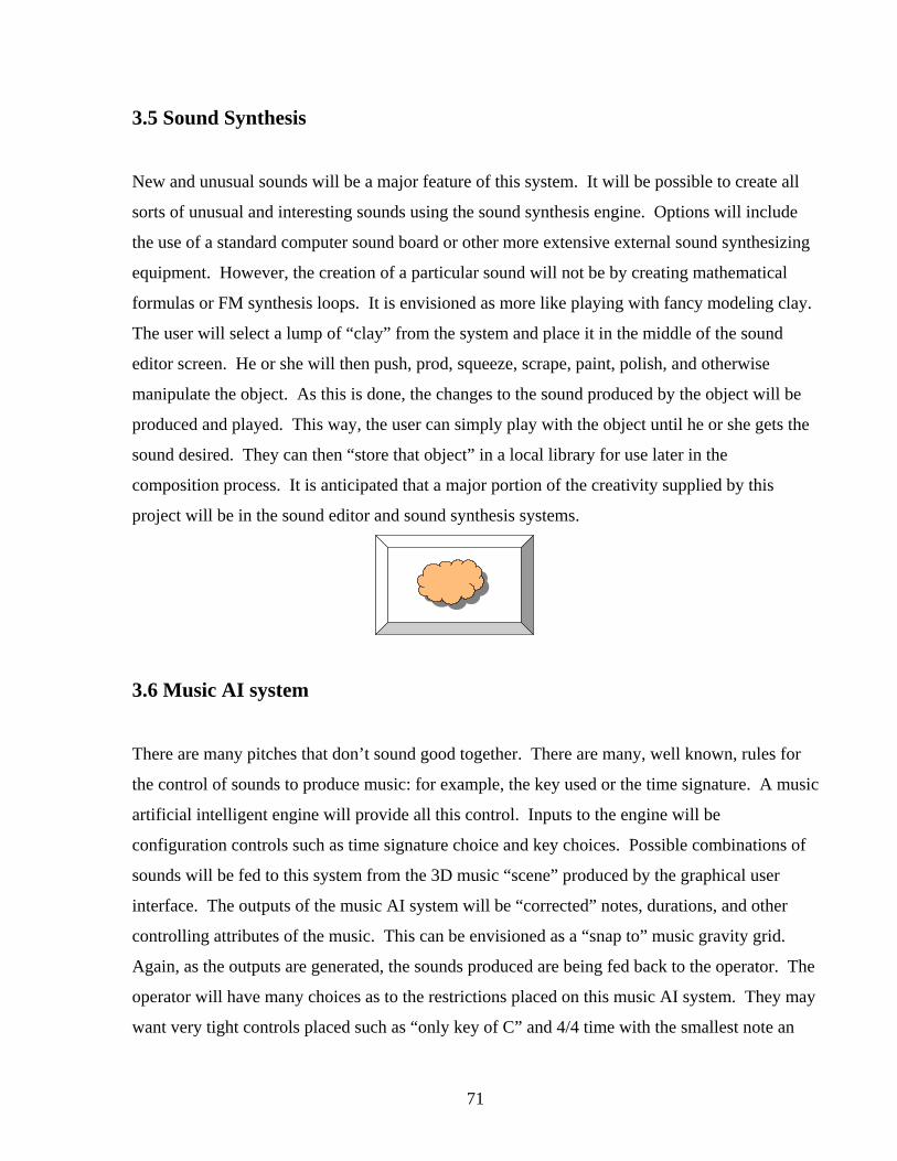
71
3.5 Sound Synthesis
New and unusual sounds will be a major feature of this system. It will be possible to create all
sorts of unusual and interesting sounds using the sound synthesis engine. Options will include
the use of a standard computer sound board or other more extensive external sound synthesizing
equipment. However, the creation of a particular sound will not be by creating mathematical
formulas or FM synthesis loops. It is envisioned as more like playing with fancy modeling clay.
The user will select a lump of “clay” from the system and place it in the middle of the sound
editor screen. He or she will then push, prod, squeeze, scrape, paint, polish, and otherwise
manipulate the object. As this is done, the changes to the sound produced by the object will be
produced and played. This way, the user can simply play with the object until he or she gets the
sound desired. They can then “store that object” in a local library for use later in the
composition process. It is anticipated that a major portion of the creativity supplied by this
project will be in the sound editor and sound synthesis systems.
3.6 Music AI system
There are many pitches that don’t sound good together. There are many, well known, rules for
the control of sounds to produce music: for example, the key used or the time signature. A music
artificial intelligent engine will provide all this control. Inputs to the engine will be
configuration controls such as time signature choice and key choices. Possible combinations of
sounds will be fed to this system from the 3D music “scene” produced by the graphical user
interface. The outputs of the music AI system will be “corrected” notes, durations, and other
controlling attributes of the music. This can be envisioned as a “snap to” music gravity grid.
Again, as the outputs are generated, the sounds produced are being fed back to the operator. The
operator will have many choices as to the restrictions placed on this music AI system. They may
want very tight controls placed such as “only key of C” and 4/4 time with the smallest note an

72
eighth note. Or, they may want wide open variations and 1/32 notes. The results will vary
greatly with these configuration inputs.
3.6 File Format
One of the problems with 3D computer graphics today is the proliferation of 3D file formats. It
seems there are now hundreds of choices for storing graphical scenes. Each major package like
“Soft Image”, “3D Studio Max”, or “Light Wave” have their own proprietary formats. And there
are many open formats like PGN and other very simple formats. It is anticipated that there will
need to be a simple compressed format to store the original music composition scenes. It doesn’t
appear that any of the ones currently available fit this particular application. Of course, the final
music could be stored in any standard format. .Wav files would store exactly the digitized
sounds. MIDI files would store more compactly but not provide exact sounds when played with
different synthesizers.
4. Summary
The first efforts in producing this software are already underway. A computer science Masters
student who is also a musician has begun work on the preliminary parts of design. Other
applications for a system like this have been suggested. Music has often been used in mental
health therapy and there is the possibility that looking at the songs created by clients may help in
locating mental defects.
RSB, Bridger Canyon, June 25, 2002
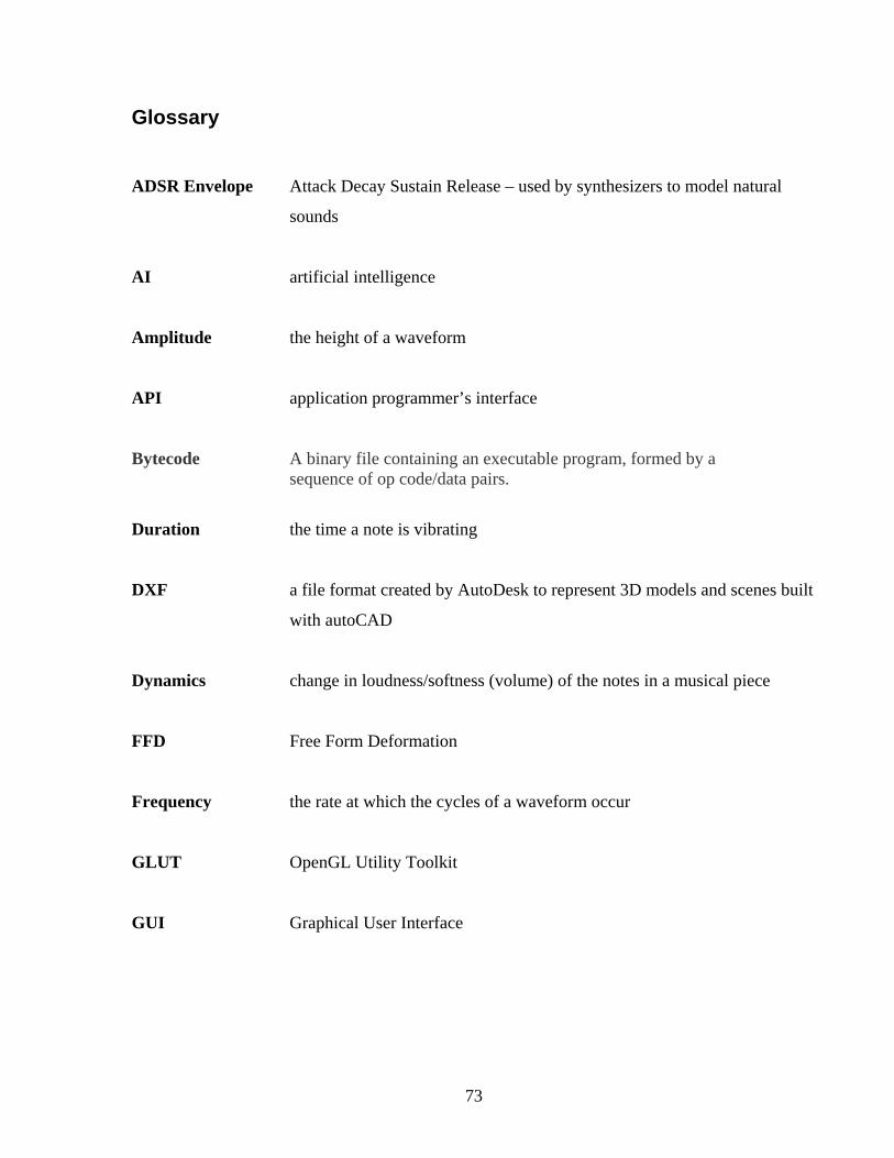
73
Glossary ADSR Envelope Attack Decay Sustain Release – used by synthesizers to model natural
sounds
AI artificial intelligence
Amplitude the height of a waveform
API application programmer’s interface
Bytecode A binary file containing an executable program, formed by a sequence of op code/data pairs.
Duration the time a note is vibrating
DXF a file format created by AutoDesk to represent 3D models and scenes built
with autoCAD
Dynamics change in loudness/softness (volume) of the notes in a musical piece
FFD Free Form Deformation
Frequency the rate at which the cycles of a waveform occur
GLUT OpenGL Utility Toolkit
GUI Graphical User Interface

74
MIDI Musical Instrument Digital Interface. MIDI files store the control
information for a musical composition. A standard language that allows
instruments, devices, software and hardware from different manufacturers
to communicate.
OpenGL A platform independent application programmer’s interface (API)
that allows programmers to write programs that access graphics
hardware.
Oscillator Fundamental building blocks in sound synthesizers that are
generated algorithmically in virtual synthesizers and are capable
of creating repetitive waveforms. Sine wave, sawtooth, step,
square, and triangular waveforms are possible.
Particle system A technique for modeling irregular natural structures, such as fire, smoke,
clouds, fog, and explosions, with a collection of independent objects, often
represented as single points. Each particle has its own motion and property
parameters.
Pinch glove 3D input device system by Fakespace, Inc. in which the user
wears gloves on both hands that complete a conductive path
when contact occurs between any two or more fingers, or thumbs,
which allows a variety of “pinch” gestures that an application can
map actions to.
Pitch the frequency at which a note makes air vibrate
Pixel Picture element, the smallest discrete component of an image on a
computer screen

75
Sequencer A device that can manipulate recorded music: play, record, fast-forward
and rewind on separate tracks
Siggraph ACM Special Interest Group on Computer Graphics and Interactive
Techniques
Subtractive technique which creates musical timbres by filtering complex
Synthesis waveforms generated by oscillators, typically by applying a lowpass filter
to the sound
Synthesizer an electronic musical instrument designed to produce artificially
generated sound by the creation and manipulation of artificial
waveforms using techniques such as additive, subtractive,
FM, and physical modeling synthesis
Tempo speed of the pulse or beat of a musical composition
Timbre the quality or “color” of a musical tone that helps distinguish it from other
sounds – musical instruments have different timbres because they project
specific harmonies or overtones when they vibrate the air to produce a
tone
Tremolo A rapid repetition of the same note, or an alternation between two or more
notes
Trill a musical ornament consisting of a rapid alternation between two notes
that are usually adjacent on the musical scale
Vibrato a musical effect where the pitch of a note is quickly and repeatedly raised
and lowered over a small distance for the duration of that note or sound.

76
Virtual Synth a computer program for digital audio generation that works like
a common synthesizer but is realized entirely in software
VM Virtual Machine - a piece of computer software designed to isolate the
application being used by the user from the computer. Virtual machines
have different versions that are written for various computer platforms, so
any platform with a version of the VM can operate an application written
for the VM. This eliminates the need to produce separate versions of the
application for each platform.
Volume the intensity of a tone - the loudness/softness of a note – the
dynamics
VRML Virtual Reality Modeling Language
Waveform The shape of a sound produced by an oscillator that determines the timbre
of the sound. Waveform shapes include sine, pulse, sawtooth, square and
triangle waves. Different sounds have different shaped waves.
Widget Often used in graphical user interfaces, a widget is a standardized on-
screen representation of a control that may be manipulated by the user that
is usually a combination of a graphic symbol and some program code to
perform a specific function. Scroll bars, buttons, and text boxes are all
examples of widgets.

77
References [1] UCSC Electronic Music Studio, Computer Music (So Far).
URL: http:// arts.uscs.edu/EMS/Music/equipment/computers/history/history.html
[2] ITGS Main …Graphics and Movie Making. History of Computer Graphics.
URL: http://www.geocities.com/CollegePark/5323/history.htm
Source of Reference: Morrison, Michael, Becoming a Computer Animator.
[3] Nelson, G. Oberlin Conservatory of Music, Oberlin, OH. Who Can Be a
Composer: New Paradigms for Teaching Creative Process in Music.
URL: http://timara.con.oberlin.edu/~gnelson/papers/who/who.pdf
[4] Smith, S., Williams, G. A Visualization of Music. Proceedings of the
8th Conference on Visualization '97, 1997, pp. 499-503.
[5] Hiraga, R., Mizaki, R., Fujishiro, I. Performance Visualization – A New Challenge
to Music Through Visualization. ACM Multimedia Conference 2002.
URL: http://www.bunkyo.ac.jp/~rhiraga/pubs/ACMMM2002.pdf
[6] Kubelka, O. Department of Computer Science and Engineering, Czech Technical
Institute, Prague / Czech Republic. Interactive Music Visualization.
URL: http://www.cg.tuwien.ac.at/studentwork/CESCG/CESCG-2000/OKubelka
[7] Farrar, E. A Method for Mapping Expressive Qualities of Music to Expressive
Qualities of Animation.
URL: http://www.accad.ohio-state.edu/~efarrar/thesis/process.htm
[8] Farrar, E. Understanding the Importance of Musical and Visual Factors in Creating
Mood in Animated Film.
URL: http://www.accad.ohio-state.edu/~efarrar/thesis/proposal6.0.pdf
78
[9] Britton, D., Ox, J. Two Performances in the 21st Century Virtual Color Organ.
IEEE Multimedia. July – September 2000. Vol. 7, No.3. p. 6 – 9.
URL: http://www.computer.org/multimedia/mu2000/u3toc.ht
[10] Ox, J. A Complex System for the Visualization of Music, Including the Journey
from 2D to Virtual Reality.
URL: http://www.bway.net/~jackox/complexity.html
[11] Fels, S., Mase, K., Mulder, A. Mapping Virtual Object Manipulation to Sound
Variation. 1997.
URL: http://www.sfu.ca/~amulder/personal/vmi/ss/sigmus97-p.pdf
[12] Fels, S., Mase, K., Mulder, A. Design of Virtual 3D Instruments for Musical
Interaction. Graphics Interface Conference 1999.
URL http://www.sfu.ca/~amulder/personal/vmi/ss/GI99-p.pdf
[13] Subotnick, M. Creating Music.
URL: http://www.creatingmusic.com
[14] Coagula – Industrial Strength Color-Note Organ.
URL: http://hem.passagen.se/rasmuse/Coagula.htm
[15] DrawSound.
URL: http://scumby.com/bfudge/drawsound
[16] Bunk, J. Music Draw 3.2.
URL: http://www.hitsquad.com/smm/programs/Music_Draw
[17] Visual Orchestra.
URL: http://www.hot-shareware.com/mp3-audio/visual-orchestra
79
[18] ArtSongTM.
URL: http://www.hot-shareware.com/mp3-audio/artsong
[19] Cathedral PitchWeb.
URL: http://www.monroestreet.com/Cathedral/pitchweb/index.html
[20] Farbood, M., Jennings, K., Pasztor,E. HyperScore: A Graphical Approach to
Composing Music.
URL: http://www.media.mit.edu/hyperins/projects/hyperscore.html
[21] Angel, E. OpenGL – A Primer. Addison-Wesley Publishing Company, Inc. 2002.
[22] Baker, S. Concerning MUI, PUI, and GLUI.
URL: http://sjbaker.org/steve/ommiv/mui_pui_glui.html
PUI URL: http://plib.sourceforge.net/pui
[23] Rademacher, P. GLUI User Interface Library.
URL: http://www.cs.unc.edu/~rademach/glui
GLUI URL: http://www.cs.unc.edu/~rademach/glui/#download
[24] Shape Transformation Technique
URL: http://www.dh.aist.go.jp/research/dressdummy/FFDexp_e.html
[25] Blender
URL: http://www.blender3D.com
[26] The Graphics File Formats Page
URL: http:// www.dcs.ed.ac.uk/home/mxr/gfx/3d-hi.html
[27] 3D Canvas
URL: http://www.amabilis.com/products.htm
80
[28] Amorphium
URL: http://www.amorphium.com/products/amorphium.html
[29] What is a Synthesizer?
URL: http://www.musicandlight-unlimited.com/audio/whatissynthesizer.htm
[30] Glossary of Electronic Music Terms
URL: http://www.knhmusic.com/html/musicterms/T.html
[31] SubSynth
URLs: http://www.sonicspot.com/subsynth/subsynth.html
http://subsynth.sourceforge.net
[32] Sawcutter
URL: http://www.hot-shareware.com/mp3-audio/sawcutter
[33] Vrml2OGL
URL: http://www.softlookup.com/preview/dis23141.html
[34] VRML2GL
URL: http://cyberia.dnsalias.com/Gfd.Dev.Tool01.htm
[35] Astle, D., Hawkins, K. OpenGL Game Programming Prima Publishing 2001.
[36] OpenAL
URL: http://www.openal.org
[37] Squeak
URL: http://www.squeak.org

81
[38] Guzdial, M. Squeak: Object-Oriented Design with Multimedia Applications.
Prentice Hall 2001.
[39] Ingalls, D., Kaehler, T., Kay, A., Maloney, J., Wallace, S. Back to the Future: The Story of
Squeak, A Practical Smalltalk Written in Itself. Proceedings of the 12th ACM SIGPLAN
conference on Object-oriented Programming, Systems, Languages, and Applications. 1997.
URL: ftp://st.cs.uiuc.edu/Smalltalk/Squeak/docs/OOPSLA.Squeak.html
[40] Squeak download
URL: http://www.squeak.org/download/index.html
[41] Introducing Morphic
URL: http://www.phaidros.com/DIGITALIS/englisch/sqk/sqk00030.htm