A Computational Study of Structural Designs for a Small ...
31
1 Research Article A Computational Study of Structural Designs for a Small- diameter Composite Vascular Graft Promoting Tissue Regeneration Mazin Salaheldin Sirry 1 , Peter Zilla 1 , Thomas Franz 1,2 * 1 Cardiovascular Research Unit, Chris Barnard Division of Cardiothoracic Surgery, 2 Centre for Research in Computational and Applied Mechanics, University of Cape Town, Cape Town, South Africa Abbreviated title: Structural designs for tissue regenerative vascular graft *Corresponding Author: Cardiovascular Research Unit Faculty of Health Sciences University of Cape Town Private Bag X3 Observatory, 7935 South Africa Tel: +27 21 406 6418, Fax: +27 21 448 5935 Email address: [email protected]
Transcript of A Computational Study of Structural Designs for a Small ...

1
Research Article
A Computational Study of Structural Designs for a Small-diameter Composite Vascular Graft Promoting Tissue
Regeneration
Mazin Salaheldin Sirry1, Peter Zilla1, Thomas Franz1,2*
1Cardiovascular Research Unit, Chris Barnard Division of Cardiothoracic Surgery,
2Centre for Research in Computational and Applied Mechanics,
University of Cape Town, Cape Town, South Africa
Abbreviated title: Structural designs for tissue regenerative vascular graft
*Corresponding Author:
Cardiovascular Research Unit
Faculty of Health Sciences
University of Cape Town
Private Bag X3
Observatory, 7935
South Africa
Tel: +27 21 406 6418, Fax: +27 21 448 5935
Email address: [email protected]
tommy
Typewritten Text
Published in Cardiovascular Engineering and Technology. Full reference: Sirry MS, Zilla P, Franz T. A computational study of structural designs for a small-diameter composite vascular graft promoting tissue regeneration. Cardiovasc Eng Tech, 2010, 1(4), 269-81
tommy
Typewritten Text
tommy
Typewritten Text

2
ABSTRACT
Purpose: The structural integrity and arterial mechanics are important aspects for tissue
regenerative vascular grafts with ingrowth permissible porous scaffolds. This paper presents a
computational study of structural designs for a small-diameter vascular graft comprising
porous polyurethane scaffold and knitted reinforcement mesh using Nitinol and polyurethane
wire, respectively.
Methods: Finite element models of the porous scaffold with the knitted mesh as embedded or
external reinforcement were generated using validated constitutive models for porous
polyurethane and Nitinol. Simulating a luminal pressure of up to 200 mmHg, deformations
and stresses were recorded in porous scaffold and knitted mesh.
Results: The models predicted compliance between 1.2 and 15.7 %/100mmHg for the
reinforced grafts and 65.1 and 106.4 %/100mmHg for the non-reinforced grafts. For the
reinforced grafts, maximum stress was 97.0, 28.2 and 0.055 MPa in Nitinol wire,
polyurethane wire and porous polyurethane scaffold, respectively, at 120mmHg. The
corresponding maximum strain was 0.27, 5.0 and 22.5%. Stress and strain remained safe in
the Nitinol mesh and the porous polyurethane but became critical in the polyurethane mesh
between 120 and 200 mmHg. Despite compression due to luminal pressure load, the porous
scaffold remained ingrowth permissible for cells, capillaries and arterioles up to 200 mmHg.
Conclusions: The outcomes of this study provided preliminary concepts for the structural
designs for a tissue regenerative composite vascular graft towards improved mechanical
performance and structural integrity. The implemented modelling approach can be used in the
further development and optimization of small-diameter tissue-regenerating vascular grafts.
Keywords: blood vessel; vascular prosthesis; tissue engineering; finite element method;
arterial mechanics

3
1. INTRODUCTION
Atherosclerosis and arteriosclerosis are two common arterial diseases referring to hardening,
narrowing and loss of elasticity in major arteries.26 If not treated, they can lead to ischemia or
infarction in the supplied organ.4 A common treatment for these diseases involves
intervention either by using assistive devices to relieve and support the artery as in the
balloon angioplasty and endovascular stenting or by replacement or bypassing of the diseased
artery with a vascular graft. Arterial and venous grafts (bioprostheses) are preferred to
synthetic grafts; however, the long-term success of small and medium calibre bioprostheses is
challenged due to the frequently encountered thrombosis, occlusion and aneurism.8 In
addition, other factors such as age, disease or prior usage limit the availability of
bioprosthetic grafts for patients requiring redo procedures.23
Synthetic grafts have been used as alternatives to bioprostheses. In small diameter synthetic
grafts, the long-term patency is limited due to the lack of endothelialisation, anastomotic
intimal hyperplasia and surface thrombogenicity.36 Tissue regeneration provides promising
avenue for the development of vascular grafts. This approach, whether aiming at composite
implants combining synthetic materials with living cells and tissue or at the complete
replacement of initially implanted materials by regenerated tissue, requires ingrowth
permitting (i.e. porous) scaffolds with structural properties tailored for implantation in the
arterial circulation and mimicking arterial mechanics. The complete healing of the porous
vascular graft implies interconnected pores to permit a transmural tissue ingrowth rather than
the initially applied trans-anastomotic ingrowth.24, 36

4
Porous polymeric scaffolds typically suffer from a lack of structural stiffness depending on
the degree of porosity and tendency to dilate over time owing to the viscoelastic properties of
the polymer. Suitable reinforcement of the scaffold is required to improve the structural
integrity, in particular when a small wall thickness is desired to minimise the amount of
synthetic material to be implanted.
The reinforcement of synthetic vascular grafts has been used extensively for the endovascular
repair of abdominal aortic aneurysms7, 9, 17, 19 whereas this concept is less common in the
smaller vasculature.27, 28, 32 These vascular prostheses comprise PTFE or woven polyester
grafts and Nitinol, stainless steel or Co–Cr alloy stents.7, 27
The use of Nitinol meshes, braided from 0.05 mm thick wires, has recently been reported as
constrictive external reinforcement for saphenous vein grafts in pre-clinical studies,37, 38
whereas knitted Nitinol mesh variations have been studied in vitro.30 While textile fabrics
were investigated by Yeoman et al.35 as external reinforcement for small-diameter tissue
regenerative polyurethane grafts with well defined interconnected porosity,2, 6 such knitted
meshes may lend themselves as alternative reinforcement structures.
This concept was explored in the current study of a multi-component small-diameter graft
promoting vascular tissue regeneration. The primary goal of the study was to investigate
structural designs of a porous polyurethane scaffold with knitted reinforcement mesh that
provide artery-like mechanics and long-term structural integrity. In order to potentially allow
for a complete replacement of the implanted graft with regenerated tissue, polyurethane was
considered as material for the knitted mesh in addition to the biostable Nitinol. While time
dependent changes in mechanical properties, found in degradable vascular prostheses, were

5
not considered, the effect of scaffold deformation on cellular and tissue ingrowth spaces was
an important aspect in the investigations.
2. MATERIALS AND METHODS
2.1 Geometries
The geometry of the knitted wire mesh was derived from a previous study.30 In the current
study, the inner diameter (ID) of the tubular knitted mesh was adjusted to 3.0 mm (Pro-
Engineering Wildfire® 2.0, Parametric Technology Corp., Needham, MA, USA) while
maintaining a wire thickness of 0.05 mm (see Fig. 1a). A single loop geometry, which formed
a 45° circumferential section, was extracted and imported into Abaqus CAE® 6.8-2 (Dassault
Systemes, Providence, RI, USA). The single loop geometry was used to create an assembly
of three loops arranged in longitudinally direction of the tubular mesh. Additional partial
loops were included at either longitudinal end of the loop assembly to assist with the
definition of boundary conditions. In Abaqus CAE®, the loop assembly was complemented
with a 45° section of a tubular porous polyurethane (PPU) scaffold with a wall thickness of
0.3 mm such that the loop section simulates an external (EX) or embedded (EM)
reinforcement of the PPU scaffold by the knitted mesh, see Fig. 1(b, c). In the EX assembly,
the outer diameter (OD) of the PPU scaffold matched the ID of the wire mesh. In the EM
assembly, the PPU scaffold was such that the wire mesh was situated radially in the centre
between scaffold ID and OD. The ID of the resulting composite graft was 2.40 and 2.84 mm
for the EX and EM assembly, respectively. The 45° tubular PPU sections with ID of 2.4 mm
(BG2.4) and 2.84 mm (BG2.8), respectively, and wall thickness of 0.3 mm were also used as
non-reinforced versions of the EX and EM composite grafts. The partial geometries were
assumed to be sufficient for the FE models due to the repetitive structure of the knitted mesh
and the axi-symmetry of the tubular PPU scaffold.

6
2.2 Materials and Constitutive Models
The PPU represented a scaffold structure with well-defined interconnected pores
manufactured by a phase inversion and porogen extraction technique3 using highly regular
spherical porogen of a nominal size range of 125-150 µm. The ratio of pore size to porogen
size was 1.21 ± 0.07 while the ratio of the size of the interconnecting windows to the pore
size was 0.52 ± 0.04.2 Nitinol and solid polyurethane (PU), respectively, were utilised for the
knitted wire mesh.
Abaqus® intrinsic constitutive models were used for all materials. The PPU material was
described with a fourth-order isotropic hyperfoam model valid for large strains.1
Experimentally determined material parameters35 of the PPU used in this study are
summarised in Table 1. Nitinol was represented with Abaqus® shape memory alloy user
material with experimentally obtained material parameters30 as shown in Table 2. For the
solid PU, an isotropic linear elastic model was used with an elastic modulus and material
density of 570 MPa and 1025 kg/m3,34 respectively, and Poisson’s ratio of 0.3.20, 31
2.3 Finite Element Models
Six FE models were developed from the geometries described above to compare a) PPU
grafts without reinforcement, with external wire mesh reinforcement and with embedded wire
mesh reinforcement and b) grafts reinforced with Nitinol wire mesh and with PU wire mesh:
Composite grafts with external Nitinol mesh reinforcement (NIEX) and PU mesh
reinforcement (PUEX), respectively, and the associated non-reinforced graft (BG2.4);
Composite grafts with embedded Nitinol mesh reinforcement (NIEM) and PU mesh
reinforcement (PUEM), respectively, and the associated non-reinforced graft (BG2.8).

7
The wire loops and PPU scaffold were meshed using 8-node linear brick elements. The mesh
density was set to ten elements along the wire cross-sectional circumference and six elements
in thickness direction of the PPU scaffold, resulting in a total of 20,055 and 28,579 elements
for EX and EM assemblies, respectively.
The contact between the PPU section and the wire mesh (for EX models only) and between
the individual wire loops (for EX and EM models) was defined as surface-to-surface contact
with finite sliding and exponential pressure-overclosure relationship. Master-slave contact
pairs were defined between surfaces of individual single loop parts in a sequential order
starting from the back partial loop towards the front partial loop, in such a way that loop n
acted as a master to loop n+1. Additionally, the entire surface of each wire mesh loop was set
as slave surface to the abluminal surface of the PPU section which as acted as master surface.
The pressure-clearance values were initially set to (0.5 MPa, 0 mm / 0 MPa, 0.005 mm) and
adjusted when required to achieve of numerical stability. In the embedded reinforcement
models (EX), contact between the wire mesh and the PPU section was governed by the
embedded region constraint1 that was utilized to generate the FE mesh of the wire loops
embedded in the PPU section. A frictional tangential behaviour was incorporated in the
models based on static-kinetic friction exponential decays. The static friction coefficient for
Nitinol-Nitinol contact pairs was set to 0.318 whereas the kinetic friction coefficient was
assumed to be 0.25. The static friction coefficient for the PPU-PU and PU-PU contact pairs
was set to 0.55 assuming a kinetic friction coefficient of 0.45. For the PPU-Nitinol contact
pairs, a static friction coefficient of 0.2 was used based on the reported polyurethane-metal
friction, 22, 25 with an assumed kinetic friction coefficient of 0.18. The decay coefficient was
set to 1×10⁻⁵ for all contact pairs.
The quasi-static analysis was carried out in two steps: 1) Establishment of contact between
8
the parts, and 2) application of load, a pressure uniformly distributed over the luminal surface
of the PPU section. The pressure was increased linearly over entire period of the second step
from 0 to 200 mmHg to extend over the physiological blood pressure range. Automatic time
incrementation was used to control the time increments in each step. The time period was set
to 1.0 with an initial time increment of 0.1. The size of the time increment was automatically
adjusted between minimum and maximum values of 1×10-12 and 0.025, respectively, to
achieve solution convergence.
Based on the circumferentially and longitudinally repetitive pattern of the knitted wire mesh
and the axisymmetric geometry of the tubular PPU section, axisymmetric boundary
conditions were applied to simulate the physical situation and to compensate for the
modelling of partial geometries. With the axisymmetric boundary condition, the model
surfaces (labelled with “C” in Fig. 1 b and c) on symmetry planes were restrained from
rotation around z- and r-axis and circumferential displacement along the θ-axis, and were
allowed to translate along the r- and z-axis and rotate around the θ-axis. With a second set of
boundary conditions, all longitudinal cross-sectional surfaces of the models (labelled with
“A” in Fig. 1 b and c) were restrained from translation in z-axis and rotation around the r- and
θ-axis, while they were allowed to translate along the r- and θ-axis and rotate the z-axis. The
omission of the movement of longitudinal cross-sections (“A”) in longitudinal direction (z-
axis) was adopted from a previous study30 of knitted wire mesh and was required due to the
disassociation of the mesh loops in the external reinforcement models.
The numerical stability and consistency of the models were verified with regard to element
type, mesh density, boundary conditions, contact and friction definitions by varying the
respective parameters and assessing the effect on the output parameters.

9
2.4 Data analysis
The maximum principal stress, maximum principal strain and displacement were recorded
automatically as Abaqus® output variables. The pressure-diameter relationship and the radial
compliance were determined from the pressure applied as load on the luminal surface of the
PPU section and the associated radial displacement of that surface captured during the
analysis. The pressure-diameter relationship was expressed graphically as curve of pressure
versus diameter increase, ΔD(P), with
0
0)()(
D
DPDPD
(1)
where D(P) is the diameter at pressure P and D0 is the diameter at P = 0 mmHg.
The radial compliance was calculated from using diastolic and systolic pressure and the
associated diameter values,
112
12
)( DPP
DDC
(2)
where P1 and P2 represent diastolic and systolic blood pressures, and D1 and D2 represent the
ID of the graft at diastolic and systolic pressure, respectively.
The wall compression was determined by capturing the radial displacement at all
corresponding nodes on the luminal and abluminal surfaces of the PPU section.
2.5 Validation
Numerical results were validated using experimental and numerical compliance data from
previous studies obtained for the PPU scaffold35 and the Nitinol wire meshes30 due to
unavailability of graft prototypes comprising the external and embedded reinforcement
assemblies. For comparison purposes, additional non-reinforced scaffold model (BG4.0) with
ID of 4.0 mm and wall thickness of 7.0 mm was developed utilizing the same procedure and
conditions applied for the development of BG2.4 and BG2.8 models.

10
3. RESULTS
Figure 2 illustrates for all models the pressure-diameter relationship expressed as luminal
pressure versus the relative increase in ID of the PPU scaffold. The independent parameter,
pressure, was plotted on the vertical axis in line with the convention for pressure-diameter
graphs in the medical field. The pressure-diameter change curves of the graft models with
external reinforcement displayed a slight increase in the slope at 120 mmHg, see Fig. 2(a).
This indicated radial non-linear stiffening although the predicted effect was weak. The
Nitinol mesh reinforced model (NIEX) experienced smaller dilation than the graft with PU
mesh reinforcement (PUEX). The non-reinforced PPU model (BG2.4) exhibited a
considerably increased dilation compared to the reinforced models and terminated
prematurely at a pressure of 170 mmHg. The NIEM and PUEM models of embedded
reinforcement exhibited a linear pressure-diameter relationship (Fig. 2b). Similar to the
externally reinforced models, the graft with embedded Nitinol mesh displayed the least
dilation followed by the PU mesh reinforced model, and the non-reinforced PPU model
exhibiting excessive dilation and termination at 150 mmHg.
The maximum principal stress and strain are summarized in Table 3 for the different models
at pressures of 80, 120 and 200 mmHg, distinguishing between the reinforcement mesh and
the PPU scaffold. Stress and strain in the wire mesh were larger in the externally reinforced
models compared to their counterparts with embedded reinforcement. The same applied for
the PPU scaffold with Nitinol mesh, i.e. larger stress and strain were predicted with external
reinforcement compared to embedded reinforcement. However, the opposite was observed
for the models with PU wire reinforcement; stress and strain levels in the PPU structure were

11
lower with external mesh compared to embedded mesh. In the non-reinforced PPU models,
stress and strain were between twofold to eightfold higher than the values predicted in the
associated reinforced models.
Figures 3 and 4 illustrate the distribution of the maximum principal stress in the deformed
models of external and embedded reinforcement, respectively, at 120 mmHg. Due to the large
difference in stress values in the wire mesh and the PPU structure, the components were
displayed separately providing each structure with its own contour legend. In the NIEX and
PUEX models (Fig. 3), stress concentrations were predicted in the heads and intersections of
wire loops and on the abluminal surface of the PPU scaffold. The embedded reinforcement
models NIEM and PUEM (Fig. 4) coincided with the external reinforcement models with
regard to the locations of stress concentration in the wire mesh. However, the stress
concentrations in PPU scaffold were predicted in internal elements of the PPU scaffold, but
not on the abluminal surface as observed with external mesh. The distribution of the
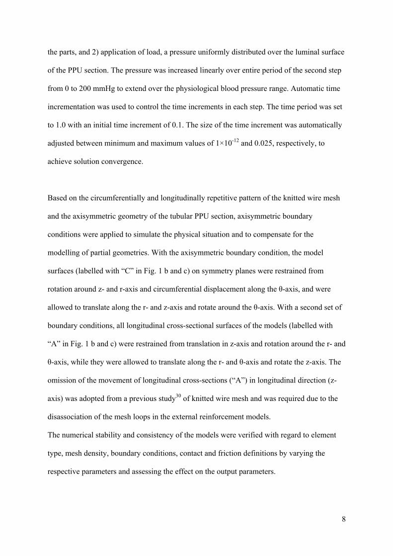
maximum principal strain and locations of strain concentrations in the PPU scaffold and wire
mesh, illustrated in Figs. 5 and 6, closely matched that of the maximum principal stress.
The wall compression of the PPU scaffold predicted at 80, 120 and 200 mmHg is illustrated
in Fig. 7. Compared to the non-reinforced models, the wall compression was substantially
increased in the external reinforcement models and slightly reduced in the embedded
reinforcement models. Within each reinforcement system, both the Nitinol-reinforced and
PU-reinforced grafts showed nearly equal levels of wall compression.
The radial compliance between 80 and 120 mmHg as the diastolic-systolic pressure range,
was predicted to be 7.0, 15.7 and 65.1 %/100mmHg for the models with external Nitinol

12
mesh, PU mesh and associated non-reinforced scaffold model, and 1.2, 6.4 and 106.4
%/100 mmHg for the grafts with embedded Nitinol mesh and PU mesh as well as the
associated non-reinforced scaffold model.
4. DISCUSSION
In this study, potential designs for tissue regenerative vascular composite grafts, comprising a
PPU scaffold and reinforcement structure, were investigated using the finite element method.
Graft models were developed for external and embedded reinforcement of a PPU scaffold
with a knitted mesh of Nitinol and PU wire, respectively, as well as for non-reinforced PPU
scaffolds. Physiological loading was simulated in numerical analyses using linearly
increasing luminal pressure between 0 and 200 mmHg. The incorporation of the knitted
reinforcement mesh considerably improved the mechanical behaviour and structural integrity
of the tissue regenerative grafts compared to the non-reinforced porous polyurethane scaffold.
The most notable effect of the reinforcement was the prevention of the excessive dilation
observed in the non-reinforced porous polyurethane scaffolds.
The incorporation of an external reinforcement reduced the radial compliance of the graft by
89% and 76% for the Nitinol mesh and PU mesh, respectively, compared to the non-
reinforced PPU scaffold. A slightly larger reduction of the radial compliance of 99% and
94% was observed for graft reinforcement with the embedded Nitinol mesh and PU mesh,
respectively. In particular the compliance values obtained with the external mesh compared
well with arterial compliance of 8.0 ± 5.9 %/100mmHg.29 In spite of the larger diameter of
the embedded reinforcement models, the lower compliance values indicated that an
embedding of the reinforcing structure in the PPU scaffold increased the radial stiffness of

13
the graft more than the external application of the mesh support.
The termination of model BG2.4 and BG2.8 when approaching 170 mmHg and 150 mmHg,
respectively, was attributed to the numerical instability associated with the excessive dilation
experienced by the models indicating structural failure. Generally, the predicted mechanical
behaviour of model BG2.4 and BG2.8 revealed high distensibility and structural weakness.
Their compliance excessively exceeded the required physiological arterial range of
8.0 ± 5.9 %/100mmHg29 emphasizing the need for mechanical enhancement.
For both reinforcement types, the Nitinol mesh provided less compliant grafts than the PU
mesh. This was expected from the 68-fold difference in the elastic modulus between Nitinol
(38,991 MPa) and solid PU (570 MPa). The non-linear stiffening of the external
reinforcement models was ascribed to the tightening of the wire loops increasing the
structural stiffness of the mesh at higher pressures. This indicated that external reinforcement
may provide more arterial like mechanics15 compared to the embedded mesh that resulted in a
linear pressure-diameter curve. A similar non-linear deformation was exhibited by a small-
diameter PU vascular graft when reinforced with weft-knitted tubular fabric33. However, the
differences between embedded and external support were not overly pronounced and did not
take into account that an external reinforcement mesh may be attached to the PPU structure
by means of an adhesive, e.g. PU layer or fibrin glue. This will affect the mechanics of the
mesh towards that of the embedded case since the movement of mesh wire loops will be
restrained. Adhesive connection between external mesh support and graft structure is also
expected to affect, reduce, the radial graft compliance.
When exposed to a luminal pressure of up to 200 mmHg, assumed as a physiological

14
maximum, the maximum stress and strain predicted in the PPU scaffold indicated recoverable
elastic deformation in the reinforced models. In the Nitinol mesh, both the maximum stress
and strain remained uncritical. The stress of 157.9 MPa reached merely 33% of the value
associated with the start of austenite-martensite phase transformation, 483 MPa.30 The
maximum strain of 0.43% did not exceed 25% of the recoverable strain of Nitinol of 2%
reported for high-cycle loadings.16 The stress and strain values predicted in the PU wire
meshes were compared to tensile properties of PU materials with elastic modulus of 534.4 ±
37.1 MPa14 similar to that used in this study (570 MPa). The ultimate tensile stress of 31.7 ±
0.6 MPa reported by Grapski and Cooper14 indicated the likelihood of onset of plastic
deformation in the PU wire between 120 and 200 mmHg for both the embedded (PUEM) and
the external mesh (PUEX). The maximum strain values predicted in the PUEM and PUEX
wire meshes reached merely 2% of the elongation at break of 355.3 ± 18.4 %.14 Apart from
plastic deformation of the graft components, debonding of mesh wire and porous
polyurethane may constitute another failure mode in the composite grafts with embedded
reinforcement mesh. The consideration of this failure mode was, however, beyond the scope
of this study. The embedded region constraint used to represent the embedded mesh in the
PPU structure in Abaqus does not provide capabilities to incorporate debonding phenomena
in the analysis. As such, a different modelling approach would be needed.
The validation of the PPU scaffold models utilized experimental and numerical data obtained
by Yeoman et al.35 for a non-reinforced PPU graft prototype (ID: 4.0 mm, wall thickness: 7.0
mm). The radial compliance was experimentally measured and numerically predicted to be
16.4 ± 4.6 and 33.9 %/100mmHg, respectively. These values exceeded the compliance
predicted for the non-reinforced models in this study (i.e. BG2.4 and BG2.8). The larger wall
thickness of the PPU prototype used by Yeoman et al., compared to the non-reinforced

15
models, was the main factor for the lower compliance in spite of the larger luminal diameter
which led to a larger circumferential wall tension at the same luminal pressure.10, 21 This was
confirmed by the decreased compliance predicted for the BG4.0 model (31.17 %/100mmHg)
which exhibited identical luminal diameter and wall thickness as the physical prototype. The
compliance predicted by model BG4.0 correlated with the numerical compliance of the PPU
prototype obtained by Yeoman et al; however, both numerical values exceeded the
experimentally determined compliance. Yeoman et al.35 attributed this overestimation to the
potential difference in material/structural properties associated with the preparation of the
prototype and the mechanical characterization of the samples used in the development of the
material model.
The Nitinol-reinforced models (i.e. NIEX and NIEM) were validated using experimental and
numerical compliance data of a Nitinol mesh prototype (ID: 3.35 mm, wire thickness: 0.05
mm). Circumferential tensile tests and volumetric displacement tests indicated a compliance
of 5.12±0.8 and 4.55±0.6 %/100mmHg, respectively (unpublished data) whereas the values
predicted with an FE model was 2.5 %/100mmHg.30 Considering that the knitted mesh rested
on the abluminal surface of the PPU scaffold in the externally reinforced models, the change
in the outer diameter of the PPU scaffold correlated with the change in the inner diameter of
the knitted mesh. While the compliance of the models in this study was generally based on
the change in inner diameter of the PPU scaffold, the apparent compliance of the knitted
mesh may be represented by the change in outer diameter of the PPU scaffold. For the NIEX
model featuring the Nitinol mesh, the latter yielded a value of 4.08 %/100mmHg. Due to
pressure attenuation through the porous scaffold wall, the transmural pressure that acted on
the scaffold-mesh interface was in fact less than the luminal pressure in the PPU scaffold.
Hence, the numerical compliance of the Nitinol mesh was somewhat underestimated.
Considering in addition the smaller diameter of the knitted mesh in this study (3.0 mm) that
16
resulted in lower circumferential wall tension compared to the Nitinol mesh of the previous
studies (3.35 mm), the data predicted by models in this study showed a reasonable agreement
with the experimental data.
The use of a linear elastic constitutive model for the solid polyurethane was assumed
satisfactory for this exploratory study. A linear elastic constitutive model has been used for
solid PU in an investigation involving the deployment of a balloon-expandable stent25 when
representing a cylindrical PU balloon applying material data of PU ureteral stents.13
One crucial aspect in tissue regenerative scaffolds is the dimension of ingrowth spaces. Care
has to be taken during the design process to ensure that ingrowth spaces remain sufficiently
large under physiological loading so as not to inhibit cellular and tissue ingrowth.35
Compression of the PPU scaffold due to luminal pressure loading is the principal parameter
affecting pore size and ingrowth spaces. Compared to the non-reinforced models, the
maximum wall compression observed at 120 mmHg was increased by 211% and 201% when
using the Nitinol and PU mesh, respectively, as external reinforcement whereas it was
reduced by 44% and 39% with an embedded Nitinol and PU mesh, respectively. In the non-
reinforced PPU model, wall compression was primarily governed by transverse contraction of
the wall associated with radial dilation and circumferential stretch whereas compression due
to the luminal pressure was secondary.35 The external reinforcement limited the radial
dilation, circumferential stretch and associated transverse contraction of the wall. As such,
thinning of the wall due to the luminal pressure was the predominant cause of wall
compression in this case, having a larger effect than the predominant mechanisms of wall
deformation in the non-reinforced models. The embedded reinforcement mesh appeared to
combine effects beneficial for limiting the wall compression, namely reduced dilation and

17
transverse wall contraction with shielding the PPU layer situated ablumenally to the
reinforcement from compression due to the luminal pressure.
The average diameter of capillaries ranges from 8 to 10 µm and the diameter of a functional
arteriole (including endothelium and smooth muscle) is approximately 30 µm.11, 12 The PPU
scaffold used in this study featured a minimum pore window diameter of approximately
65 µm.35 Recalling that the maximum wall compression predicted among the different
reinforced models was 37.24% (model NIEX at 200 mmHg), the minimum pore window
diameter would be reduced to 41 µm. This suggested that the tissue-regenerating
characteristic of all grafts was not affected since the scaffold retained permissibility for
cellular and tissue ingrowth.
The developed models helped exploring the structural design and mechanical behaviour of
the composite vascular graft. The outcomes of this study provided preliminary concepts for
the structural optimisation towards improved mechanical performance and structural integrity
of such devices. The implemented modelling approach can be used in the further
development and optimization of small-diameter tissue-regenerating vascular grafts.
FUNDING SOURCES
This study was supported financially by the National Research Foundation (NRF) of South
Africa. Any opinion, findings and conclusions or recommendations expressed in this
publication are those of the authors and therefore the NRF does not accept any liability in
regard thereto.
CONFLICT OF INTEREST STATEMENT
The authors declare that they do not have conflicts of interest with regard of this manuscript

18
and the data presented therein.
APPENDIX
Figures with essential colour discrimination: Figs. 3 to 6, in this article are difficult to
interpret in black and white. The full colour images can be found in the on-line version.
REFERENCES
1Abaqus analysis user's manual. Providence, RI, USA: Abaqus, Dassault Systèmes; 2008.
2Bezuidenhout D. Porous polymeric superstructures as in-growth scaffolds for tissue-
engineered vascular prostheses [PhD]. Stellenbosch: Stellenbosch University; 2001.
3Bezuidenhout D, Davies N, Zilla P. Effect of well defined dodecahedral porosity on
inflammation and angiogenesis. ASAIO J. 2002;48(5):465-71.
4Crowley LV. An introduction to human disease: Pathology and pathophysiology
correlations. 8 ed. Sudbury, MA: Jones & Bartlett Publishers; 2009.
5Dammak M, Shirazi-Adl A, Zukor DJ. Analysis of cementless implants using interface
nonlinear friction--experimental and finite element studies. J Biomech. 1997;30(2):121-9.
6Davies N, Dobner S, Bezuidenhout D, Schmidt C, Beck M, Zisch AH et al. The dosage
dependence of VEGF stimulation on scaffold neovascularisation. Biomaterials.
2008;29(26):3531-8.
7Desai M, Eaton-Evans J, Hillery C, Bakhshi R, You Z, Lu J et al. AAA stent–grafts: Past
problems and future prospects. Ann Biomed Eng. 2010;38(4):1259-75.
8Dobrin P, Littooy F, Golan J, Blakeman B, Fareed J. Mechanical and histologic changes in
canine vein grafts. J Surg Res. 1988;44(3):259-65.
9Ellozy SH, Carroccio A, Minor M, Jacobs T, Chae K, Cha A et al. Challenges of
endovascular tube graft repair of thoracic aortic aneurysm: Midterm follow-up and lessons

19
learned. J Vasc Surg. 2003;38(4):676-83.
10Ethier CR, Simmons CA. Introductory biomechanics: From cells to organisms. Cambridge
texts in biomedical engineering. Cambridge: Cambridge University Press; 2007.
11Fung Y-C. Biomechanics: Mechanical properties of living tissues. Second ed. Springer;
1993.
12Gamble JR, Matthias LJ, Meyer G, Kaur P, Russ G, Faull R et al. Regulation of in vitro
capillary tube formation by anti-integrin antibodies. J Cell Biol. 1993;121(4):931-43.
13Gorman SP, Jones DS, Bonner MC, Akay M, Keane PF. Mechanical performance of
polyurethane ureteral stents in vitro and ex vivo. Biomaterials. 1997;18(20):1379-83.
14Grapski JA, Cooper SL. Synthesis and characterization of non-leaching biocidal
polyurethanes. Biomaterials. 2001;22(16):2239-46.
15Holzapfel GA, Gasser TC, Ogden RW. A new constitutive framework for arterial wall
mechanics and a comparative study of material models. J Elasticity. 2000;61(1-3):1-48.
16Info sheet no. 4: Selected properties of NiTi. Memory-Metalle GmbH, Weil am Rhein.
2006. http://www.memory-metalle.de/html/03_knowhow/PDF/MM_04_properties_e.pdf.
Accessed 29/04/2010.
17Jacobs TS, Won J, Gravereaux EC, Faries PL, Morrissey N, Teodorescu VJ et al.
Mechanical failure of prosthetic human implants: A 10-year experience with aortic stent graft
devices. J Vasc Surg. 2003;37(1):16-26.
18Kim JH, Kang TJ, Yu W-R. Mechanical modeling of self-expandable stent fabricated using
braiding technology. J Biomech. 2008;41(15):3202-12.
19Kleinstreuer C, Li Z, Basciano CA, Seelecke S, Farber MA. Computational mechanics of
Nitinol stent grafts. J Biomech. 2008;41(11):2370-8.
20Konnerth J, Gindl W, Müller U. Elastic properties of adhesive polymers. I. Polymer films
by means of electronic speckle pattern interferometry. J Appl Polym Sci. 2007;103(6):3936-

20
9.
21Levy B, Tedgui A, editors. Biology of the arterial wall. Dordrecht: Kluwer; 1999.
22Mailhot B, Komvopoulos K, Ward B, Tian Y, Somorjai GA. Mechanical and friction
properties of thermoplastic polyurethanes determined by scanning force microscopy. J Appl
Phys. 2001;89(10):5712-9.
23Min HK, Lee YT, Kim WS, Yang JH, Sung K, Jun TG et al. Complete revascularization
using a patent left internal thoracic artery and variable arterial grafts in multivessel coronary
reoperation. Heart Surg Forum. 2009;12(5):244-9.
24Mooney DJ, Baldwin DF, Suh NP, Vacanti JP, Langer R. Novel approach to fabricate
porous sponges of poly(-lactic-co-glycolic acid) without the use of organic solvents.
Biomaterials. 1996;17(14):1417-22.
25Mortier P, Holzapfel G, De Beule M, Van Loo D, Taeymans Y, Segers P et al. A novel
simulation strategy for stent insertion and deployment in curved coronary bifurcations:
Comparison of three drug-eluting stents. Ann Biomed Eng. 2010;38(1):88-99.
26Newman Dorland WA. Dorland's illustrated medical dictionary. 29 ed. Philadelphia:
Saunders; 2000.
27Peynircioglu B, Ergun O, Hazirolan T, Serter T, Ucar I, Cil B et al. Stent-graft applications
in peripheral non-atherosclerotic arterial lesions. Diagn Interv Radiol. 2008;14(1):40-50.
28Sakai H, Urasawa K, Oyama N, Kitabatake A. Successful covering of a hepatic artery
aneurysm with a coronary stent graft. Cardiovasc Intervent Radiol. 2004;27(3):274-7.
29Tai NR, Salacinski HJ, Edwards A, Hamilton G, Seifalian AM. Compliance properties of
conduits used in vascular reconstruction. Br J Surg. 2000;87(11):1516-24.
30van der Merwe H, Daya Reddy B, Zilla P, Bezuidenhout D, Franz T. A computational study
of knitted Nitinol meshes for their prospective use as external vein reinforcement. J Biomech.
2008;41(6):1302-9.

21
31Wiggins MJ, Anderson JM, Hiltner A. Biodegradation of polyurethane under fatigue
loading. J Biomed Mater Res, Part A. 2003;65A(4):524-35.
32Wong G, Li J-m, Hendricks G, Eslami MH, Rohrer MJ, Cutler BS. Inhibition of
experimental neointimal hyperplasia by recombinant human thrombomodulin coated ePTFE
stent grafts. J Vasc Surg. 2008;47(3):608-15.
33Xu W, Zhou F, Ouyang C, Ye W, Yao M, Xu B. Mechanical properties of small-diameter
polyurethane vascular grafts reinforced by weft-knitted tubular fabric. J Biomed Mater Res,
Part A. 2010;92A(1):1-8.
34Yeoman MS. The design and optimisation of fabric reinforced porous prosthetic grafts
using finite element methods and genetic algorithms [Phd]. Cape Town: University of Cape
Town; 2004.
35Yeoman MS, Reddy BD, Bowles HC, Zilla P, Bezuidenhout D, Franz T. The use of finite
element methods and genetic algorithms in search of an optimal fabric reinforced porous
graft system. Ann Biomed Eng. 2009;37(11):2266-87.
36Zilla P, Bezuidenhout D, Human P. Prosthetic vascular grafts: Wrong models, wrong
questions and no healing. Biomaterials. 2007;28(34):5009-27.
37Zilla P, Human P, Wolf M, Lichtenberg W, Rafiee N, Bezuidenhout D et al. Constrictive
external nitinol meshes inhibit vein graft intimal hyperplasia in nonhuman primates. J Thorac
Cardiovasc Surg. 2008;136(3):717-25.
38Zilla P, Wolf M, Rafiee N, Moodley L, Bezuidenhout D, Black M et al. Utilization of shape
memory in external vein-graft meshes allows extreme diameter constriction for suppressing
intimal hyperplasia: A non-human primate study. J Vasc Surg. 2009;49(6):1532-42.

22
TABLES
Table 1. PPU material parameters35 used in the hyperfoam material model.
Description Unit Value
υ - 0.035
µ1 MPa 0.19262
µ2 MPa -0.03373
µ3 MPa -0.08682
µ4 MPa 0.02566
α1 - 1.2571
α2 - 1.2655
α3 - -2.6509
α4 - -4.6589

23
Table 2. Nitinol material parameters30 used in the shape memory alloy user material.
Parameter Unit Value
Austenite Young’s Modulus MPa 38992
Austenite Poisson’s Ratio - 0.46
Martensite Young’s Modulus MPa 21910
Martensite Poisson’s Ratio - 0.46
Transformation Strain - 0.042
Loading Temperature Derivative of Stress MPa/°C 0
Loading Start of Transformation Stress MPa 483
Loading End of Transformation Stress MPa 610
Reference Temperature MPa 37
Unloading Temperature Derivative of Stress MPa/°C 0
Unloading Start of Transformation Stress MPa 388
Unloading End of Transformation Stress MPa 256
Loading Start of Transformation Stress (Compression) MPa 610
Volumetric Transformation Strain - 0.04
Number of Annealings to be Performed During Analysis - 0

24
Table 3. Maximum principal stress σ (in MPa) and strain ε (in %) in the PPU scaffold and the
reinforcement mesh at 80, 120 and 200 mmHg. For non-reinforced models, the mesh was not
applicable.
80 mmHg 120 mmHg 200 mmHg
PPU Mesh PPU Mesh PPU Mesh
σ ε σ ε σ ε σ ε σ ε σ ε
NIEX 0.020 8.94 73.68 0.20 0.031 12.77 97.0 0.27 0.046 17.25 157.90 0.43
PUEX 0.036 15.43 18.76 3.44 0.054 21.41 28.18 5.01 0.063a 24.32a 33.61a 5.96a
BG2.4 0.066 27.53 - - 0.132 50.28 - - 2.54b 192.7b - -
NIEM 0.012 5.72 57.59 0.09 0.019 7.46 86.72 0.14 0.034 13.83 145.60 0.24
PUEM 0.37 16.25 18.16 2.99 0.055 22.54 26.64 4.42 0.095 32.75 45.14 7.15
BG2.8 0.081 33.41 - - 0.186 68.47 - - 2.49c 192.4c - - a predicted at 143 mmHg; b predicted at 170 mmHg; c predicted at 150 mmHg

25
FIGURES
Figure 1. Computational 3D geometry of the knitted wire mesh (a). A partially geometry of
the knitted mesh created from single loop geometry was combined with a 45º circumferential
section of the tubular PPU scaffold to obtain an externally reinforced graft (b) and a graft
with embedded reinforcement (c). Labels A and C indicate surfaces that obtained axial and
circumferential boundary conditions, respectively.

26
Figure 2. Graphs illustrating the relationship of pressure and diameter increase for different
graft models. The increase in ID was normalized to the initial ID at zero pressure. a)
Externally reinforced grafts (Nitinol mesh: NIEX, PU mesh: PUEX; *termination at
143 mmHg) and associated non-reinforced scaffold (BG2.4, **termination at 170 mmHg).
The dashed straight lines were added to enhance the illustration of increase in slope of the
NIEX and PUEX curves. b) Grafts with embedded reinforcement (Nitinol mesh: NIEM, PU
mesh: PUEM) and the associated non-reinforced scaffold (BG2.8, ***termination at 150
mmHg).

27
Figure 3. Contour plots of the distribution of the maximum principal stress (values in MPa) at
120 mmHg in the deformed PPU scaffold and the wire mesh of the externally reinforced
model for a) Nitinol wire mesh (NIEX) and b) PU wire mesh (PUEX). The wire mesh was
detached from the PPU scaffolds and assigned separate legends for display purposes. In each
model, stress concentrations were predicted on the abluminal surface of the PPU scaffold and
in the heads and at intersections of wire loops.

28
Figure 4. Contour plots of the distribution of the maximum principal stress (values in MPa) at
120 mmHg in the deformed PPU scaffold and the wire mesh of model with embedded
reinforcement with a) Nitinol wire mesh (NIEM) and b) PU wire mesh (PUEM). The wire
meshes were detached from the PPU scaffolds and assigned separate legends for display
purposes. In each model, stress concentrations were predicted in the internal elements of the
PPU scaffold and in the heads and crossovers of wire loops. For the PPU scaffold, abluminal
layers of elements were eliminated from the display to reveal the locations of stress
concentration.
29
Figure 5. Contour plots of the distribution of the maximum principal strain (values in %) at
120 mmHg in the deformed PPU scaffold and the wire mesh of the externally reinforced
model for a) Nitinol wire mesh (NIEX) and b) PU wire mesh (PUEX). The wire mesh was
detached from the PPU scaffold and assigned separate legends for display purposes. In each
model, strain concentrations were predicted on the abluminal surface of the PPU scaffold and
in the heads and at intersections of wire loops.

30
Figure 6. Contour plots of the distribution of the maximum principal strain (values in %) at
120 mmHg in the deformed PPU scaffold and the wire mesh of model with embedded
reinforcement with a) Nitinol wire mesh (NIEM) and b) PU wire mesh (PUEM). The wire
mesh was detached from the PPU scaffold and assigned separate legends for display
purposes. In each model, strain concentrations were predicted in the internal elements of the
PPU scaffold and in the heads and crossovers of wire loops. For the PPU scaffold, abluminal
layers of elements were eliminated from the display to reveal the locations of strain
concentration.

31
Figure 7. Wall compression predicted by the six models at 80, 120 and 200 mmHg. (*: The
PUEX, BG2.4 and BG2.8 models terminated at 143, 170 and 150 mmHg, respectively). A
considerable increase in wall compression was observed for models with external
reinforcement (NIEX and PUEX) compared to the associated non-reinforced model (BG2.4).
The models with embedded reinforcement (NIEM and PUEM), exhibited lower wall
compression compared to the non-reinforced model (BG2.8).