A Comprehensive Guide to Electroactive Polymers (EAP)qiw4/Academic/MEMS1082/Group 2 EAPs...
25
A Comprehensive Guide to Electroactive Polymers (EAP) Daniel Gunter, Evan Lawrence, Kaylee Levine, and Zachary Miller Abstract Electroactive polymers are a field of material that demonstrates large strain in response to electrical fields. These actuators closely emulate the stimulus response capacities of animal muscle and so are often referred to as artificial muscles. The development of highly electroactive polymer materials with actuation strains as high as 300% has sparked a wave of research and development into the capacities of EAP materials for various fields. A nonexhaustive list of potential EAP material applications includes biomimetics such as artificial muscles, active catheters, and biomimetic robots, tactile displays such as refreshable braille devices, and unmanned vehicles including aerial, underwater, and aerospace devices. EAP materials are largely classified into two categories: ionic and electric. Ionic EAP’s involve the diffusion of ions, whereas electric EAP’s are driven by an electric field. Examples of ionic EAP’s include ionic polymer metal composites, carbon nanotubes, ionic polymer gels, conductive polymers, and electrorheological fluid. Electric EAP can be further divided into piezoelectric polymers, electrostrictive polymers, dielectric elastomers, liquid crystal elastomers, and ferroelectric polymers. The following paper thoroughly investigates the history, theory, and current and future applications for the aforementioned types of EAP’s, and hypothesizes on the role this actuator technology could play in the future. Introduction Muscles are perhaps one of the most important and prevalent actuators present in the natural world. Muscles, the elastic tissue responsible for all life functions, control the movement of body parts and the operation of organ systems through the command of a nerve and conversion of adenosine triphosphate (ATP) into mechanical energy (1). Actuators belong to the general denomination of transducers, which can be defined as a device that transforms energy from one type to another. Actuators, as opposed to sensors, the other class of transducers, which simply monitor a system, impose a condition on a system. In response to a stimulus from its
Transcript of A Comprehensive Guide to Electroactive Polymers (EAP)qiw4/Academic/MEMS1082/Group 2 EAPs...

A Comprehensive Guide to Electroactive Polymers
(EAP)
Daniel Gunter, Evan Lawrence, Kaylee Levine, and Zachary Miller
Abstract
Electroactive polymers are a field of material that demonstrates large strain in response to electrical fields. These actuators closely emulate the stimulus response capacities of animal muscle and so are often referred to as artificial muscles. The development of highly electroactive polymer materials with actuation strains as high as 300% has sparked a wave of research and development into the capacities of EAP materials for various fields. A nonexhaustive list of potential EAP material applications includes biomimetics such as artificial muscles, active catheters, and biomimetic robots, tactile displays such as refreshable braille devices, and unmanned vehicles including aerial, underwater, and aerospace devices. EAP materials are largely classified into two categories: ionic and electric. Ionic EAP’s involve the diffusion of ions, whereas electric EAP’s are driven by an electric field. Examples of ionic EAP’s include ionic polymer metal composites, carbon nanotubes, ionic polymer gels, conductive polymers, and electrorheological fluid. Electric EAP can be further divided into piezoelectric polymers, electrostrictive polymers, dielectric elastomers, liquid crystal elastomers, and ferroelectric polymers. The following paper thoroughly investigates the history, theory, and current and future applications for the aforementioned types of EAP’s, and hypothesizes on the role this actuator technology could play in the future.
Introduction
Muscles are perhaps one of the most important and prevalent actuators present in the natural world. Muscles, the elastic tissue responsible for all life functions, control the movement of body parts and the operation of organ systems through the command of a nerve and conversion of adenosine triphosphate (ATP) into mechanical energy (1). Actuators belong to the general denomination of transducers, which can be defined as a device that transforms energy from one type to another. Actuators, as opposed to sensors, the other class of transducers, which simply monitor a system, impose a condition on a system. In response to a stimulus from its

environment, which can consist of an energy input in any form (electrical, magnetic, thermal, optic, etc.), an actuator yields a mechanical output (2). Generally, an actuator can be considered anything that converts energy into motion (3). From this definition of actuators, it is clear to see how natural muscles fall into their scope.
As well as being of interest due to their natural presence in biological systems, the scientific interest in muscles is due to the fact that muscles are highly optimized (4). Between species of animals, there is little variation in the basic muscle properties, signifying that muscles, through millions of years of evolution, are the ideal instrument for providing animals the ability of controlled mechanical motion. Accordingly muscles are not only commonly studied by scientists, but are also seeked to be emulated by engineers.
Though long a subject of interest to scientists and artists as early as the Renaissance, the study of muscles as a link between physics and life began with the discovery of “animal electricity” by Luigi Galvani in 1792. After observing that a frog muscle contracts when its nerve receives an electric shock, Galvani concluded that “animal electricity” drives the contraction of muscles (5). With centuries of development of research into the function of muscles, the understanding of the way that muscles operate has been advanced from Galvani’s breakthrough to the scientific knowledge of today. This understanding in a basic form is that a neurotransmitter allows the introduction of sodium ions, which cause a charge that depolarizes the muscle membrane, triggering the release of calcium ions. The release of these ions then cause muscle fibers to shorten and thus contract (6).
In the spirit of biomimicry, a design philosophy governed by the doctrine that every problem that humans seek to solve through technology is present in nature along with a time-tested solution (7), researchers have turned to muscles as inspiration for manmade actuators as well as a standard for which to strive. With muscles, nature has provided a lightweight and elegant means of generating motion, a feat that human technology has historically achieved through motors, which are often bulky thus unfit for many applications. The objective to induce motion without the use of motors has led way to the field of research into artificial muscles. One of the earliest known references to the undertaking of developing artificial muscles comes from Robert Hooke, who in the 1670s proposed the design of artificial muscles actuated by gunpowder (8).
In more recent history, the class of materials that has garnered significant attention in this field of muscle emulation is polymers. This field of research further follows the naturally occuring model, as biological muscles operate through the bonding between two polymers, actin and myosin (4). Polymers are made of long, repeating chains of molecules, which gives them many useful characteristics. They can be lightweight, cheap, and flexible to fit a vast array of applications (9). Polymers can be categorized as active or passive, where active polymers can be controlled by external stimuli, such as electrical, chemical, thermal, pneumatic, and magnetic excitations. It was first discovered that polymers could be stimulated in 1949 when it was observed that collagen filaments reversibly contract when dipped in acid solutions and reversibly

expand when put in alkali solutions, an example of chemical stimulus. This early breakthrough sparked research into creating synthetic polymers as scientists began to strive toward mimicking human muscles. However, the field strayed from its chemical origin, as the convenience, practicality, and progress in electrical stimulation shifted the focus from chemical stimuli to electrical. This spurred interest in electroactive polymer (EAP) materials (4).
EAP materials are polymers that change size or shape in response to electric stimulation. The most desirable property of EAP’s is large deformations in response to relatively small input. The concept of EAP materials was first demonstrated in 1880 by Wilhelm Roentgen, when he applied charges to a rubber band with a fixed end and a free end with a mass attached (10). In 1899, M.P. Sacerdote further progressed the field of research in the area with his formulation of the strain response to electric field activation (11). In 1925, the field was further developed with the discovery of electret, a piezoelectric polymer made by the cooling of carnauba wax, rosin, and beeswax, which were then subjected to a DC bias field (12). EAP materials became of interest again in 1969 after the discovery of piezoelectricity in polyvinylidene fluoride (13).
However, it was not until the 1990s that research into EAP materials started to improve, making it a promising technology with apparently limitless applications. Before this time, while EAP materials existed as evidenced by the associated history previously discussed, their use was restricted due to the relatively low strains generated. However, a new wave of research was energized by breakthroughs in the 1990s that produced EAP materials with higher strain capabilities. As a result, EAPs have been developed that are capable of obtaining over 300% strain (14). This powerful actuation potential as well as the beneficial properties of polymers- the ability to be formed into various shapes, flexibility, and resilience- has opened the door for EAP to be applied in diverse ways. The possibility of unhampered actuation without relying on gears, bearings, and motors makes the potential of EAP materials of particular interest and has attracted scientists and engineers from an array of disciplines. The improvements in EAP materials that make them stronger, more robust, and more efficient, would “enable faster implementation of science fiction ideas into engineering reality,” according to Yoseph Bar-Cohen, a leading researcher at the forefront of EAP breakthroughs (15).
To garner attention for the field of EAP materials and increase excitement over the technology as well as provide an opportunity to further the progress of EAP materials and their applications, in 1999 Bar-Cohen developed the grand challenge for EAP actuated robotics and challenged EAP experts to develop an EAP-actuated robotic arm capable of beating a human opponent in a wrestling match. In 2006, the first competition was held, prompting the development of three EAP-actuated arm wrestling robots, all of which lost to the 17 year old human representative, with the best robot having a hold time of 26 seconds (16). Though the robots ultimately failed against their human opponent, the results of the competition were considered an encouraging starting point, with the 26 second hold providing hope for the future progress of EAP actuated robots. The objective of the competition is indicative of the ambitions of the EAP community and the direction in which they strive: the creation of artificial muscles

that are superior to human biological muscles. It is anticipated that advancements towards this goal will bring with it advancements in EAP applications, particularly in the medical area with superior prosthetics (4).
One technology that demonstrated the smooth and sleek actuation capabilities of EAP’s was the first commercially available product to use EAP actuators, a fish-robot that was released to the market in 2002 in Japan by Eamex. The fish-robot swam in water without the use of batteries or a motor, but using EAP materials that bend when stimulated. The fish was powered by inductive coils on the top and bottom of the fish tank (17).
Historically, EAP materials have been divided into two classes, ionic and electrical, each with their respective assets and areas for improvement. The actuation of ionic EAP’s involves the flow of ions within a polymer layer, while that of electrical EAP’s is due to electrostatic forces between two electrodes (18). In general, electronic EAP’s demonstrate the capability to hold a DC bias induced displacement while ionic EAP’s tend not to sustain displacements. Another challenge associated with ionic EAP’s is the need to maintain their wetness. Ionic EAP’s tend to produce large bending displacements but low actuation forces and have slow responses. They also require an electrolyte to operate in air and demonstrate low electromechanical coupling. Electronic EAP’s, on the other hand, have demonstrated quick response times. Additional advantages of electronic EAP’s is their ability to operate for a long time in room conditions and large actuation forces. However, the voltage required for electrical EAP’s tends to be much larger than that of ionic, with their activation fields possibly approaching breakdown voltage, which poses a problem when it comes to medical applications (17). These constraints and advantages of EAP materials have influenced the applications of different types of EAP’s in various disciplines and have directed the narrative of research in the field of EAP’s.
Applications
Investigation of EAPs uses has led to the discovery of many potential applications. A majority of the applications discussed are theoretical, but further development can bring these exciting products to fruition. Application 1 - Braille
In 1825, the development of braille code had a significant impact on the blind community by making reading and writing more accessible. These abilities are essential for everyday life, and not having them can be frustrating. The invention of braille improved the wellbeing of the blind through multiple avenues, including education, occupation, and recreation.
However, in today’s world, the blind are facing a new kind of challenge: digital media. According to a study done by Pew Research Center, 88% of American teens have access to a

mobile phone, 87% of American teens have access to a computer, and 58% of American teens have access to a tablet device. (19). In order to keep up with the digital world, an improvement of the braille code is required.
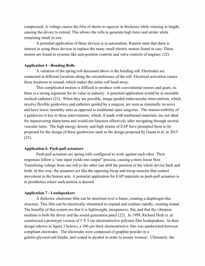
In 1998, Yoseph Bar-Cohen hypothesized that EAP materials could improve these devices by allowing multiple actuators to be installed in close proximity with one another without interference. The basic concept consists of electrodes on one side of an EAP film and pins on the other side that activate the individual dots in the array. A voltage is applied to the dot element, which causes a thickness reduction. This lowers the dot, effectively removing it from the user’s touch. In other words, all dots rest in the “up” position. In this position the dots can be felt by the user. When information needs to be displayed, a computer will apply a voltage to the dots that are not needed. This voltage lowers the dot element, putting it in the “down” position and making it unable to be felt. See figure 1 for a diagram of this theoretical setup.
Since 2003, several haptic displays that use EAPs were proposed as a solution by various research groups. The basis of these full-page displays consisted of an array of tiny levers. These levers had braille dots attached on one end and were connected to a device that communicated when to raise and lower the dots via the levers. A standard braille page has twenty-five lines with forty characters in each line, which adds up to six thousand to eight thousand dots per page. The dots themselves are raised 0.5mm, which requires an actuation force of at least 0.15N. A refreshable display would have to mimic this, as well as have the ability to retract the dots in order to load new information. In the past similar concepts would have been attempted with purely mechanical pieces, but through the development of these more recent devices, researchers have shown that such devices can be actuated with the use of EAPs (20). Application 2 - Biomimetic Robots
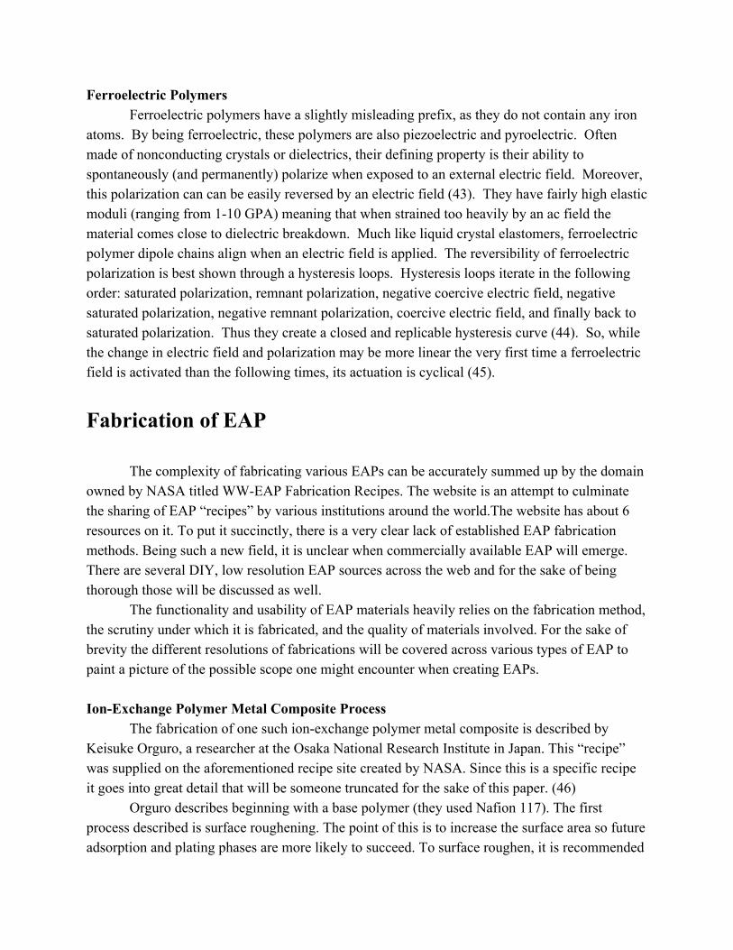
A purpose of developing biomimetic technology is to improve prosthetics. There is a real desire for artificial limbs to look and behave realistically, and researchers are realizing that this can be made possible with the use of EAPs.
Figure 2 shows a picture of an artificial hand. The hand consists of a rolled dielectric elastomer EAP and four IPMC-based pieces. The EAP is an actuator that causes the hand to move linearly. The four IPMC pieces are actuators that can bend. The system works together by executing both the linear and the bending movements simultaneously. The linear actuator moves the hand toward an object and the bending actuators serve as fingers by bending around an object and then gripping it and lifting it (21). Application 3 - Linear actuators
A very common form of linear actuators are called spring rolls. Several layers of prestrained laminated dielectric elastomer sheets are wrapped around a helical spring. The spring supports the circumferential prestrain while the lengthwise prestrain holds the spring
compressed. A voltage causes the film of sheets to squeeze in thickness while relaxing in length, causing the device to extend. This allows the rolls to generate high force and stroke while remaining small in size.
A potential application of these devices is in automation. Reports state that there is interest in using these devices to replace the many small electric motors found in cars. These motors are found in systems like seat-position controls and valve controls of engines. (22)
Application 4 - Bending Rolls
A variation of the spring roll discussed above is the bending roll. Electrodes are connected at different locations along the circumference of the roll. Electrical activation causes these locations to extend, which makes the entire roll bend away.
This complicated motion is difficult to produce with conventional motors and gears, so there is a strong argument for its value in industry. A potential application would be in steerable medical catheters (22). When they are possible, image-guided endovascular interventions, which involve flexible guidewires and catheters guided by a surgeon, are seen as minimally invasive and have lower mortality rates as opposed to traditional open surgeries. The maneuverability of a guidewire is key to these interventions, which, if made with traditional materials, are not ideal for maneuvering sharp turns and would not function effectively after navigating through several vascular turns. The high energy density and high strains of EAP have prompted them to be proposed for the design of these guidewires such as the design proposed by Ganet et al. in 2015 (23).
Application 6- Push-pull actuators
Push-pull actuators are spring rolls configured to work against each other. Their responses follow a “one input yields one output” process, causing a more linear flow. Transfering voltage from one roll to the other can shift the position of the whole device back and forth. In this way, the actuators act like the opposing bicep and tricep muscles that control movement in the human arm. A potential application for EAP materials as push-pull actuators is in prosthetics where such motion is desired. Application 7 - Loudspeakers
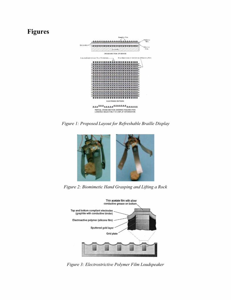
A dielectric elastomer film can be stretched over a frame, creating a diaphragm-like structure. This film can be electrically stimulated to expand and contract rapidly, creating sound. The benefits of this system are that it is lightweight, inexpensive, flat, and that the vibration medium is both the driver and the sound-generation panel (22). In 1999, Richard Hedt et. al. constructed a prototype version of 5 X 5 cm electrostrictive polymer film loudspeakers. In their design (shown in figure 3 below), a 100 μm thick electrostrictive film was sandwiched between compliant electrodes. The electrodes were composed of graphite powder in a gelatin-glycerol-salt binder, and coated in alcohol in order to ensure wetness. Ultimately, the

team’s prototype was able to generate up to 80 dB of sound and reach frequencies of over 390 Hz (23).
Application 8 - Sensors
All dielectric elastomer devices experience a change in capacitance when they move. If calibrated, this change in capacitance could be used as a sensor, and be incorporated into fabrics, fibers, strips, or coatings. An application of this could be a fabric sensor that measures the tension in a seatbelt. If there is tension, as in if the seat belt is stretched over the person and buckled in, the elastomer is stretched and its capacitance changes. This change in capacitance could then be read as positive or “yes, the seatbelt is buckled.” If there is not tension, there would be no change in capacitance, so the response would be negative or “no the seatbelt is not buckled”. This could be combined with a weight sensor in the seat to provide a safety feature that encourages the use of seatbelts while driving or riding in a car (22). Application 9 - Surface Texturing and Smart Surfaces
While still theoretical, this application is an exciting prospect. Sheets of polymers are coated with patterns of electrodes. Arrays of dots or other shapes are attached to the electrodes, allowing them to be raised. The raising and lowering of the dots creates different reflective patterns, and if these patterns could be controlled on demand, it essentially behaves like an active camouflage. This has many applications, especially with military as stealth technology.
The patterns could also be used as adaptive mechanisms for reducing air drag on moving objects. A sheet of this material on a car or an airplane could adapt to wind currents and create rivets in itself, improving aerodynamic characteristics (22).
Application 10 - Power Generators
As previously mentioned, EAP materials experience a change in capacitance when they move. This opens up the possibility for use in energy harvesting devices. One design currently being tested is an elastomer that sits in the sole of a shoe. A voltage is constantly being sent across the elastomer so that when walking, a person’s heel strikes the elastomer and causes a deflection. This deflection results in a change in capacitance, which influences the voltage. This new voltage is then converted into usable electrical energy. An average person taking one step every second can produce roughly one watt of power using this device. This concept has attracted a lot of attention from the military. The modern soldier carries a lot of electronic devices, and in order to power these devices, he/she must also carry batteries. Replacing these batteries with energy harvesting boots would be very beneficial as it would reduce the amount of things a soldier has to carry with him/her as well as reduce the load he/she has to carry around. There has also been interest in social service applications such as policemen and firefighters, who face similar issues in the field (22).

This was just a sample of a variety of emerging artificial muscle technologies. Through further development, EAPs have the potential to not only replace the current actuators used today, but also may lead to new applications beyond the current realm of possibility. The direction of future EAP applications is discussed below. Future Applications
As they are inspired by human muscles, it follows that in future applications, it is believed that artificial muscles made with EAP materials can improve and replace their biological predecessor. One possible direction for the application of EAP’s is in the development of exoskeletons. Exoskeletons, a part of an animal that provides support and protection, could be used to provide support for elderly and disabled people and improve mobility. The non-bulky actuation provided by EAP materials would allow for smooth motion unhindered by motors and heavy metal and allow the subject to move in a way that closely resembles natural healthy motion. It has also been hypothesized that these exoskeletons can have military applications. With adequate progress, the development of EAP’s capable of large forces could give way to “super soldiers” capable of running faster and carrying heavier weapons due to an augmentation of their natural strength by an EAP-actuated exoskeleton. Another potential application of EAP artificial muscles acting as actual muscles is in the creation of artificial limbs. It is proposed that EAP’s be used to allow a person to control their artificial limb in a realistic manner (25).
It is also suggested the EAP’s could be used to direct flight by moving within the wing of an airplane. In one study, the potential of EAP’s for use in unmanned aerial vehicles (UAVs) was explored. EAP’s were mounted onto paper, the structural material for the UAV, which allowed it to become electromechanically active and capable of actuation that controlled flight. The ways in which a UAV can be controlled include programming it before take-off, providing it with sensors that instruct its flight, or remotely controlling it with a wireless system. The first two methods appear promising for the deployment of inexpensive UAVs, which has led rise into the research of disposable UAVs using substrates such as paper as the main structure. Many of the electrical components (sensors, batteries, antennas, etc) have been demonstrated, but the technology still required a means of mechanical actuation with appropriate form and weight to be integrated into the UAV, for which EAP’s are proposed (26).
EAP materials have also been proposed for a number of space applications. A 2015 study found that prolonged exposure of ionic EAP actuators in space conditions would not impinge on their function (27). EAP devices that have been developed for application in space include a dist wiper, gripper, robotic arm, and a miniature rake. It is hoped that EAP materials will be used in the future to make space-flight cheaper, more reliable, and more effective (4).

Discussion
At their most basic level, Electroactive polymers function by changing in size or shape
following exposure to a voltage or current. As mentioned above, EAPs can be most broadly differentiated into two categories: ionic and electronic (28). The theoretical function for ionic EAPs is best characterized by the manipulation of ions, while that of electronic electronic EAPs is best characterized by the manipulation of dipoles (29). Understanding underlying theory of these different categories and their subdivisions, as well as their transduction mechanisms, device performance, and device characterization, is imperative to recognizing this technology’s potential.
Ionic vs. Electronic Electronic EAPs
The primary benefit of electronic EAPs is the large strain (upwards of 40% strain) they can obtain. However, these massive strains require large amounts of voltage, which could be an issue depending on how the artificial muscle is used. (It is important to note that the actual driving force of the actuator is the electric field produced by the voltage. This comes into play when looking at dielectric design.) A subdivision of electronic EAPs is Dielectric Elastomer Actuators (DEAs). These actuators are capacitors with very sensitive electrodes and a dielectric film. When a voltage is applied to the DEA, the electrodes cause both an attraction of opposite charge and a repulsion of like charge across the dielectric. This generates stress in the dielectric and causes it to compress. See figure 4 for a detailed image on what this looks like. “The key to large strain is to make both the electrodes and the elastomer highly compliant without sacrificing dielectric strength and conductivity.” This stress and resulting strain eventually leads to the work per unit volume per stroke of the actuator.
A breakthrough in DEA design came from the insight that while voltages are required in the use of electronic EAPs, it is the electric field produced by the voltage that actually drives the actuation. Through either increasing dielectric constant, or by using thinner sheets of elastomer, the same electric field can be maintained while also reducing the required voltage. An example of this is seen in Figure 5. The DEA shown is comprised of multiple layers of DEAs rolled into tubes. This allows the multiple DEAs to apply their actuation forces in parallel, summing to one large force (30).

Ionic EAPs The benefit of using ionic EAPs is the low voltage required for actuation. The material
itself has mobile ions within the polymer phase that can be influenced by an electric field. This electric field either pulls ions into a region of the material (causing swelling), or pushes them out of a region (causing contraction). The voltages required for this are low (1-7 [V]), but the resulting energies are high because of the small spacing between the ions and electric charges. Ionic EAPs have also shown difficulty in sustaining their displacements.
A subdivision of ionic EAPs are carbon nanotube (CNT) actuators. These materials are known for their remarkably high tensile modulus (~640 [GPa]) and tensile strength (20 - 40 [GPa]). These properties are observed for individual CNTs, however, and current manufacturing technology restricts assembly of CNTs to yarns or sheets, which ultimately lowers their performance. When an electric field is applied to the CNT, an effect similar to that of the electronic EAPs occurs. However, instead of two electrodes interacting, it is all the charges that were injected into the Nanotube that are attracting and repelling (30). Ionic Theory IPMC
Ionic polymer-metal composites (IPMCs) consist of three main layers, a polyelectrolyte membrane layer squeezed between two high-surface-area compliant electrodes. One end of the structure is cantilevered, leaving the other end free to move. The material of this polyelectrolyte layer can vary, but it is most regularly a perfluorinated or sulfonated polymer membrane. These polymer membranes are chosen for their selectively-porous properties; cations are able to flow freely through the membrane while anions are restricted by the IPMC. This is a key component of IPMC function, as the movement of positively-charged cations ultimately yields the bending and actuation of the IPMC.
The electrode layers are either physically coated or chemically plated, with one layer positively-charged and the other negatively-charged. Thus, when a voltage is applied to the IPMC (typically between 1 and 4 V), the cations naturally gravitate towards the negative side of the electrode. As a response to the mass migration of cations, the cathode side grows in size while the anode side shrinks. This imparts a bending moment throughout the IPMC and, in turn, a highly controllable actuation. In fact, this behavior has been found to reliably occur at frequencies up to 100 Hz (31).

CNT In their most basic form, carbon nanotubes (CNT) are comprised of a sheet of graphite
that is rolled into either a single-walled or multi-walled nanotube (32). The tubular nature of the carbon-carbon bonds, coupled with CNTs suspension in an electrolyte bath, creates a conductive path through which electrons can flow. Electrons are injected into this pathway, affecting the ionic charge balance between carbon nanotubes and the electrolyte. Actuation of CNTs is entirely contingent on this adjustment to the ionic charge balance. When electrons are added to the path, the central influx of negative charge attracts the positively charged carbon-carbon barrier, causing the tube to swell in functional diameter (33). When electrons are retracted from the pathway, CNTs grow longitudinally because the absence of negative charge leaves the positive charges of each C-C bond alone to interact with one another. Since like charges repel, the carbon nuclei separate further and the tube elongates (32). Ultimately, CNT actuators can be divided into three major categories: electrostatic, electromechanical, and chemical. For electrostatic actuation specifically, bias voltage inputs of 30 V often result in tube extensions of around 1500 nm.
IPG
At their most basic level, ionic polymer gels (IPGs) are comprised of fixed charges, cations, and anions. While the charge of these fixed charges (as well as the solution and gel types) affects the direction of actuation, the physical actuation of these gels is entirely contingent on the mobility of these cations and anions. They are generally situated within a solution containing cations, anions, and water. IPGs adjust in density when their surrounding environment oscillates between acidic and alkaline. This oscillation is controlled through electrical stimulation between an anode and a cathode, between which sits the gel. Upon stimulation, the cathode side increases in alkalinity while the anode side increases in acidity. This results in bending of the gel.
As mentioned above, the direction that the gel bends can vary from material to material. The two primary bending types for negatively fixed charges are shown below in figure 6
Bending occurs because cations are much more mobile than anions in a negative fixed charge configuration due to the repulsion of like charges. Thus, when the electrode is powered, cations rush to the cathode side, in turn bending the actuator in the same direction. Choonghee Jo et al. found that ionic polymer gels achieved normalized tip deflections of ~0.84 with an applied DC Voltage of 6 V (34).

CP The base of a conductive polymer (CP) is made up of a polymer chain that alternates
between single and double bonds. The structure emits a series of electronic bands that drastically vary in energy separation from the conduction to the valence band. Initially, conductive polymers behave as insulators. In order for the polymers to exhibit actuation, they must be excited to a conductive state. This can be achieved using a process called doping.
Doping entails adding certain impurities to a semiconductor in order to alter its conductivity. Impurities adjust the space taken up by the structure (in this case the conductive polymer) and the number of valence electrons it holds. Depending on these characteristics, the ease of electron travel from one orbital to the next varies. Should the added impurity have a low amount of valence electrons, it creates a “hole” for easier electron travel with minimal energy input. Should the added impurity have a high amount of valence electrons, they instantly fill the valence band, and the overflowing electrons are forced to move to higher energy bands, like the conduction band. These newly added electrons can now move easily within the higher band level (35). The different composition of the doped material (in terms of size, valence) delineate between n-type doping and p-type doping, both of which will affect the shape changes of the conductive polymer actuator. N-type doping is the addition of significant amounts of electrons (or reduction of the neutral polymer chain), while p-type doping adds material that is lacking in electrons, in turn oxidizing the neutral polymer chains (36).
During these oxidation and reduction processes, the polymer swells in size and bends, much like ionic polymer gels. These size and shape changes are due to the doped polymer receiving electrical stimulation and an in turn receiving or expelling ions. Conductive polymer EAPs can reach oscillations of about 40 Hz with miniscule input voltages (typically between 1-5 V). Electrorheological
The final type of ionic electroactive polymer analyzed in this review is electrorheological fluid (ERF). Unlike the previously explained types of ionic EAPs, which maintain a constant state, electrorheological fluid is primarily defined by its ability to transition between liquid and gel (37). In other words, it has an adjustable viscosity. ERFs are made up of 0.1-100 µm particles suspended in an insulating base fluid. The particles and the fluid have different dielectric constants, meaning that when the ERF is exposed to an electric field, there is an induced dipole moment. This moment organizes the ERF’s field line structure, in turn adjusting its properties. Unfortunately, there is not a significant amount of data regarding the performance of ERFs.

Electronic Theory Piezoelectric Polymers
Understanding the concept of piezoelectricity, and its bi-directionality, is fundamental to grasping the function of most electronic electroactive polymers. By definition, a piezoelectric material is a dielectric with a non-symmetric center that generates electric charges in response to mechanical stress, or conversely creates a mechanical stress in response to an electric field (38). Interestingly, the relationship between stress and induced charge per unit area is completely linear for piezoelectric materials, making their actuation highly predictable. Additionally, piezoelectric materials are highly desirable for actuation applications, as they have notable speed, precision, and mechanical power (39). There are various subdivisions for piezoelectric polymers, namely bulk piezopolymers, voided charged polymers, and piezocomposites. For the sake of concision, this theory section only discusses the theory behind semi-crystalline polymers (particularly polyvinylidene fluoride bimorph actuators), a subset of bulk piezopolymers (38), as these are more prevalent in the industry than other categories.
As indicated by the moniker “bimorph,” PVDF actuators have two layers of material, who work in opposition of one another to create a flexion displacement (29). The following two constitutive equations illustrate the linear nature of semi-crystalline polymers:
Di = εTijEj + dijkTjk (1) Sij = dijkEk + sEijklTkl (2)
Where:
● Di = Electric Displacement ● εTij = Dielectric Constant ● Ej = Electric Field ● Tjk = Mechanical Stress ● dijk = Piezoelectric Coefficient ● Sij = Strain ● sEijkl = Compliance
PVDF actuators receive a voltage input which translates into the flexion of the bimorph with controllable output angle and displacement.

Electrostrictive When exposed to a DC biased electric field, electrostrictive polymers demonstrate
pseudo-piezoelectric effects (40). In other words, DC electric fields trigger a mechanical actuation in electrostrictive polymers. The primary difference between electrostrictive and piezoelectric materials is that electrostrictive materials do not exhibit a linear relationship between electrical input and strain. In fact, the two are related quadratically in electrostrictive polymers, meaning that reversing the electric field will not change strain values in the slightest. Dielectric Elastomers
Dielectric elastomers (DEs) can be constructed from a vast array of materials, but they are most often constructed from silicone and acrylic elastomer, as these materials were able to withstand the most significant strains. They have two compliant electrodes surrounding these aforementioned central elastomeric films. Naturally, one end of the electrode is positive while the other is negative. The total thickness of a DE is often between 10 and 100 µm An electric field (in the form of bias voltage between 500 V and 10 kV) is applied to the DE, with positive charges directed at the anode side and negative charges directed at the cathode side. This compels the dielectric elastomer to squeeze, as the like charges repel each other while the opposite charges (primarily those concentrated on the ends of the film) attract (41). These charge interactions are often referred to as coulombic forces. As a result, the DE expands in width and decreases in thickness. DEs are notably efficient in power-use for two reasons. Firstly, they are electrostatic devices, meaning that they only consume power during periods of active size change. Moreover, much like regenerative braking in automobiles, dielectric elastomers recover some energy following actuation. Liquid Crystal Elastomers
Aptly named liquid crystal elastomers, LCEs demonstrate both crystalline and liquid properties. They actuate between nematic and isotropic states. During a nematic phase, molecules show ordered directionality. Their level of directional order directly indicates their level of anisotropy, with more anisotropic materials demonstrating a higher likelihood to be sensitive to external stimuli (such as an electric field). In the isotropic phase, the liquid crystals become completely random with no preference regarding their orientation (42). The transition from nematic to isotropic takes less than a second, while the reverse takes approximately ten seconds. In switching between phases, the LCEs adjust their length, hence their designation as an electroactive polymer.
The stimulus that catalyzes these phase changes is temperature. Higher temperatures yield an ordered liquid crystal and cooler temperatures yield a disordered liquid. It is the temperature changes that create strains reaching up to 400% in LCEs. A chart linking temperature to strain is shown below in figure 7 (33).
Ferroelectric Polymers Ferroelectric polymers have a slightly misleading prefix, as they do not contain any iron
atoms. By being ferroelectric, these polymers are also piezoelectric and pyroelectric. Often made of nonconducting crystals or dielectrics, their defining property is their ability to spontaneously (and permanently) polarize when exposed to an external electric field. Moreover, this polarization can can be easily reversed by an electric field (43). They have fairly high elastic moduli (ranging from 1-10 GPA) meaning that when strained too heavily by an ac field the material comes close to dielectric breakdown. Much like liquid crystal elastomers, ferroelectric polymer dipole chains align when an electric field is applied. The reversibility of ferroelectric polarization is best shown through a hysteresis loops. Hysteresis loops iterate in the following order: saturated polarization, remnant polarization, negative coercive electric field, negative saturated polarization, negative remnant polarization, coercive electric field, and finally back to saturated polarization. Thus they create a closed and replicable hysteresis curve (44). So, while the change in electric field and polarization may be more linear the very first time a ferroelectric field is activated than the following times, its actuation is cyclical (45).
Fabrication of EAP The complexity of fabricating various EAPs can be accurately summed up by the domain
owned by NASA titled WW-EAP Fabrication Recipes. The website is an attempt to culminate the sharing of EAP “recipes” by various institutions around the world.The website has about 6 resources on it. To put it succinctly, there is a very clear lack of established EAP fabrication methods. Being such a new field, it is unclear when commercially available EAP will emerge. There are several DIY, low resolution EAP sources across the web and for the sake of being thorough those will be discussed as well.
The functionality and usability of EAP materials heavily relies on the fabrication method, the scrutiny under which it is fabricated, and the quality of materials involved. For the sake of brevity the different resolutions of fabrications will be covered across various types of EAP to paint a picture of the possible scope one might encounter when creating EAPs. Ion-Exchange Polymer Metal Composite Process
The fabrication of one such ion-exchange polymer metal composite is described by Keisuke Orguro, a researcher at the Osaka National Research Institute in Japan. This “recipe” was supplied on the aforementioned recipe site created by NASA. Since this is a specific recipe it goes into great detail that will be someone truncated for the sake of this paper. (46)
Orguro describes beginning with a base polymer (they used Nafion 117). The first process described is surface roughening. The point of this is to increase the surface area so future adsorption and plating phases are more likely to succeed. To surface roughen, it is recommended

to sandblast. Following the sandblasting is an ultrasonic washing. This will remove the materials used during the sandblast, as well as other residues that may have appeared on the surface. Ultrasonic washing occurs by soaking the membrane in a fluid, which is agitated by the ultrasonic frequencies. This forces the contaminants off of the membrane.
Following the ultrasonic wash, it is recommended to treat the membrane in a diluted HCl bath for roughly thirty minutes. This continues to remove impurities as well as other loose ions. Following the HCl bath it is recommended to again wash the membrane in a deionized water bath for thirty minutes to rinse off the acid. The result of this wash is two fold, because it also swells the membrane and can be stored in deionized water.
Now that the membrane has been prepared, the creation of an EAP begins. Since this is an ion-exchange metal polymer, a core component of it’s functionality is the ion-exchange. The purpose of this process is to control the ions in the substrate for greater mobility and precision. Immerse the membrane in a metal complex such as platinum. Specific concentrations yield different results. Orguro emphasize the importance of this concentration. The ion-exchange adsorption process will take place usually over one night.
The primary and secondary plating processes are similar. Orguro also emphasizes the importance of the concentration of sodium borohydride. The result of its application is a layer of platinum particles on the surface of the membrane. By adding the sodium borohydride reagent in careful iterations, and slowly raising temperature, a black layer of Pt particles form on the surface.
The secondary plating process highly depends on the success of the first plating process however Orguro recommends combining Pt with hydroxylamine, hydrochloride, and hydrazine in various specific concentrations to get the perfect second plating. If done successfully, gray metallic layers will form on the surface of the membrane.
It is very clear that this process has been heavily refined by Orguru, however this is just one EAP using one base polymer. Given that this is the most thorough recipe easily accessible on the internet, it is easy to conclude that other thorough developments of EAP materials are needed (46). Carbon Nanotubes
Another popular and widely studied form of EAP are carbon nanotubes (CNTs). This cutting edge material has a pretty wide array of fabrication methods, all with their own strengths. These methods are arc discharge in a liquid media, laser vaporization (laser furnace method), and chemical vapor deposition. All of these methods require purification processes at the end to deliver a more refined product. The following information regarding CNT fabrication was organized and disseminated in a peer reviewed paper by Mohsen Jahanshahi and Asieh Dehghani Kiadehi. A summary of its relevant information is as followed (47).
In arc discharge, two graphite electrodes are placed vertically around 1-2mm apart. The anode is drilled and filled with a catalyst metal powder. It functions similar to a DC electric arc

discharge reactor. The anode chamber is connected to a vacuum line with a diffusion pump. After the chamber is evacuated rarefied ambient gas is introduced. When a DC arc discharge is applied between the rods, the anode is consumed and what is left are fullerenes.
Laser Vaporization utilizes a high energy laser which is effective despite the carbons high boiling temperature. By introducing a high temperature buffer gas, the newly formed CNT’s can be transported to a cold trap which separates them from the gas. Due to using highly controllable lasers, laser vaporization produces high quality CNT’s with precise diameter control. This comes at a cost since lasers are not economically efficient for many labs, as well as the high quality graphite rods require.
In chemical vaporization a hydrocarbon vapor is thermally decomposed in the presence of a metal catalyst. The carbon source is then placed in gas phase into a reaction chamber where compounds such as methane are used to break the gaseous carbon into reactic atomic carbon. The carbon is then diffused towards a catalyst coated substrate. The catalyst allows the nanotubes to “grow” up the the substrate. This is actually a very popular method and has been used for various applications since the early 1960s.
Catalyst choice is crucial when fabricating CNT’s. Usually the catalysts chosen are transition metals but can be a mixture of the two. What is crucial is the melting point of the catalyst, because this heavily influences the synthesis temp of the CNT. They can also greatly affect shape, diameter, and defect count.
Purifying the CNT production is very important because there are usually a lot of impurities. Purification processes generally are combined for greater effectiveness. Impurities range from metal particles (such as catalysts), amorphous carbon that was not properly turned into CNT, and CNTs with the wrong number of shells.
During oxidation, the impurities are affected greater than the CNTs. This usually is used to get rid of leftover metal catalyst. Acid treatment is usually used to reduce metal and other amorphous carbon by reducing it. Annealing is sometimes used to melt away the metal. Ultrasonic baths can be used to do disperse left over amorphous carbon and incorrect CNTs (47). DIY Resources
Despite the complicated and thorough creation of previously mentioned forms of EAP, there also are a few modern resources online with simple kitchen countertop guides. While they lack the sophistication and precision of wet chemical based creations, they still are technically EAPs.
One such online resource is Materiability. This website hosts other similar DIY projects. They reference this project as coming from the Swiss Federal Laboratories for Materials Science and Technology (48).

Essentially, the project describes creating a frame for a membrane of acrylic elastomer, which is then surrounded by a steel frame that can freely expand and retract. This is used to help stretch the membrane over the frame. By coating the surface in graphite powder and connecting it with copper tape, it is transformed to a still frame to an EAP. It can be actuated using around 5kV. The shape that is chosen for the frame acts as a rest phase. When the voltage is applied, the frame expands in several directions (48).
Figures
Figure 1: Proposed Layout for Refreshable Braille Display
Figure 2: Biomimetic Hand Grasping and Lifting a Rock
Figure 3: Electrostrictive Polymer Film Loudspeaker

Figure 4: Dielectric Elastomer Actuator
Figure 5: DEA Tube Comprised of Multiple Rolled up Layers
Figure 6: Ionic Polymer Gel’s Two Bending Directions

Figure 7: Chart Linking Strain to Temperature for Liquid Crystal Elastomers
References
1. Nordqvist, Christian. (April 11, 2017). “Muscles: Why are they important?” Medicalnewstoday.com. https://www.medicalnewstoday.com/articles/249192.php
2. Wang, Qing Ming. (2017). Lecture 1: Introduction and Transducer Models. University of Pittsburgh. http://www.pitt.edu/~qiw4/Academic/MEMS1082/Lecture1.pdf
3. “What is an Actuator? Types of Actuator.” Engineeringinsider.org. https://engineeringinsider.org/actuator/2/
4. Bar-Cohen, Yoseph. (2004). Electroactive Polymer (EAP) Actuators as Artificial Muscles - Reality, Potential, and Challenges (2nd Edition). SPIE. Retrieved from https://app.knovel.com/hotlink/toc/id:kpEPEAPAA3/electroactive-polymer/electroactive-polymer
5. Martonosi, Anthony N. (July 20, 2000). “Animal electricity, Ca2+ and muscle contraction. A brief history of muscle research.” Acta Biochimica Polonica, Volume 47 (No. 3), 493–516.
6. Openstax. (Feb 26, 2016 ). Anatomy and Physiology. OpenStax CNX. http://cnx.org/contents/[email protected].
7. “What is Biomimicry?” Biomimicry.org. https://biomimicry.org/what-is-biomimicry/ 8. The Uses of the Future in Early Modern Europe (Eds: A. Brady, E. Butterworth),
Routledge, New York 2009.

9. Brinson, Hal F., & Brinson, Catherine L. (2008). Polymer Engineering Science and Viscoelasticity: An Introduction. Retrieved from https://link.springer.com/content/pdf/10.1007%2F978-0-387-73861-1.pdf
10. Roentgen WC. (188)0. “About the changes in shape and volume of dielectrics caused by electricity.” Annu. Phys. Chem. 11, 771–786.
11. Sacerdote MP. (1899). “On the electrical deformation of isotropic dielectric solids.” J. Phys. 3 Series, 282–285.
12. Kao, Kwan C. (2004). Chapter 5- Electrets. Dielectric Phenomena on Solids. Retrieved from https://www.sciencedirect.com/topics/materials-science/electrets.
13. Bar-Cohen, Yoseph, et al. (September 1996). “Polymer Piezoelectric Transducers for Ultrasonic NDE.” NDTnet Volume 1 (No. 9). Retrieved from https://www.ndt.net/article/yosi/yosi.htm
14. Ha, Soon M. et al. (March 9, 2007). “Interpenetrating networks of elastomers exhibiting 300% electrically-induced area strain.” Smart Materials and Structures Volume 16. S280-287.
15. Huang, Gregory T. (December 1, 2002). “Electroactive Polymers.” MIT Technology Review. https://www.technologyreview.com/s/401750/electroactive-polymers/#comments
16. “The armwrestling match between an EAP actuated robotic arm and a human.” https://ndeaa.jpl.nasa.gov/nasa-nde/lommas/eap/EAP-armwrestling.htm
17. Bar-Cohen, Yoseph. (July 27, 2004). “EAP as artificial muscles: progress and challenges.” Proceedings SPIE Volume 5385. Retrieved from https://pdfs.semanticscholar.org/9587/bcd6c458dbb33e6cad3ec439a4f8beefe379.pdf
18. Kim, Onnuri, et al. (March 26, 2018). “Low-voltage-driven soft actuators.” Chem. Commun. Volume 54. 4895-4904. Retrieved from https://pdfs.semanticscholar.org/9587/bcd6c458dbb33e6cad3ec439a4f8beefe379.pdf
19.Lenhart, Amanda. (April 5, 2015). “A Majority of American Teens Report Access to a Computer, Game Console, Smartphone, and a Tablet.” Pew Research Center. Retrieved from http://www.pewinternet.org/2015/04/09/a-majority-of-american-teens-report-access-to-a-computer-game-console-smartphone-and-a-tablet
20.Bar-Cohen, Yoseph. (September 11, 2009). “Electroactive polymers for refreshable Braille displays.” Society of Photographic Instrumentation Engineers. Retrieved from (http://spie.org/newsroom/1738-electroactive-polymers-for-refreshable-braille-displays?SSO=1
21.Bar-Cohen, Yoseph. n.d. “Artificial Muscles using Electroactive Polymers (EAP): Capabilities, Challenges, and Potential.” Retreived from

https://trs.jpl.nasa.gov/bitstream/handle/2014/37602/05-1898.pdf?sequence=1&isAllowed=y
22.Ashley, Steven. “Artificial Muscles.” (October 2003). Scientific American. Retreived from https://ndeaa.jpl.nasa.gov/nasa-nde/nde-aa-l/clipping/Scientific-Ameican-article-Oct-03.pdf
23. Heydt, R., Pelrine, R., Joseph, J., Eckerle, J., Kornbluh, R. (2000). “Acoustical performance of an electrostrictive polymer film loudspeaker” The Journal of the Acoustical Society of America. 107. https://asa.scitation.org/doi/pdf/10.1121/1.428266?class=pdf.
24. Ganet, F. et al. (December 17, 2015). “Development of a smart guide wire using an electrostrictive polymer: option for steerable orientation and force feedback.” Sci. Rep. 5, 18593; doi: 10.1038/srep18593 (2015).
25. Fador, Marek, et al. “New Trends in Application of Artificial Muscles for Automation Devices used in Non-productive Sector.” https://pdfs.semanticscholar.org/0262/50aadb9d6a2a5862e63a0ca7baeee9fce9ec.pdf
26. Grau, Gerd. (August 15, 2016). “Printed unmanned aerial vehicles using paper-based electroactive polymer actuators and organic ion gel transistors.” Microsystems and Nanoengineering Volume 2 (No 16032). Retrieved from https://www.nature.com/articles/micronano201632#rightslink
27. Punning, Andres, et al. (2014). “Ionic electroactive polymer artificial muscles in space applications.” Scientific Reports Volume 4 (No. 6913). Retrieved from https://www.nature.com/articles/srep06913
28. Belluco, Paolo. (2018, August). EAP - ElectroActive Polymers. Retrieved from http://home.deib.polimi.it/gini/introEAP.pdf.
29. Pérez, R., Král, M., Bleuler, H. (2012). Study of polyvinylidene fluoride (PVDF) based bimorph actuators for laser scanning actuation at kHz frequency range. Sensors and Actuators, 183, 84-94, Retrieved from https://doi.org/10.1016/j.sna.2012.05.019.
30. Mirfakhrai, Tissaphern; Madden, John; and Baughman, Ray. (April 2007). Polymer artificial muscles. Science Direct - Materials Today. Retrieved from https://www.sciencedirect.com/science/article/pii/S1369702107700482
31. Ionic (wet) electroactive polymers. Retrieved from https://www.optotune.com/about-us/index.php?option=com_content&task=view&id=39&Itemid=52.
32. Qu, L., Peng, Q., Dai, L., Spinks, G. M., Wallace, G. G., Baughman, R. H. (2008). Carbon Nanotube Electroactive Polymer Materials: Opportunities and Challenges. Electroactive Polymer Actuators and Sensors, 33, 215-224. Retrieved from https://www.cambridge.org/core/journals/mrs-bulletin/article/carbon-nanotube-electroacti
ve-polymer-materials-opportunities-and-challenges/090016905913EB7D9A0FB791F2B325B8.
33. Bar-Cohen, J. (2004). Bellingham, WA: SPIE 34. Jo, C., Naguib, H. E., Kwon, R. H. (2011). Fabrication, modeling and optimization of an
ionic polymer gel actuator. Smart Materials and Structures, 20. Retrieved from http://iopscience.iop.org/article/10.1088/0964-1726/20/4/045006/meta.
35. Fundamentals: Doping: n- and p- semiconductors. Retrieved from https://www.halbleiter.org/en/fundamentals/doping/.
36. Casiday, R., Frey, R., (1998). Bonds, Bands, and Doping: How do LEDs Work? Retrieved from http://www.chemistry.wustl.edu/~edudev/LabTutorials/PeriodicProperties/MetalBonding/MetalBonding.html.
37. Weisstein, E. W., Electrorheological Fluid. Retrieved from http://scienceworld.wolfram.com/physics/ElectrorheologicalFluid.html.
38. Ramadan, K. S., Sameoto, D., Evoy, S., (2014). A review of piezoelectric polymers as functional materials for electromechanical transducers. Smart Materials and Structures, 23, Retrieved from https://doi.org/10.1088/0964-1726/23/3/033001.
39. Fu, Y. Harvey, E. C., Ghantasala, M. K., Spinks, G. M. (2005). Design, fabrication and testing of piezoelectric polymer PVDF microactuators. Smart Materials and Structures, 15, Retrieved from https://doi.org/10.1088/0964-1726/15/1/023.
40. Yin, X., Lallart, M., Cottinet, P. (2016). Electrostrictive polymers: Energy harvesting via smart materials. Retrieved from https://phys.org/news/2016-01-electrostrictive-polymers-energy-harvesting-smart.html.
41. Brochu, P., Pei, Q. (2009). Advances in Dielectric Elastomers for Actuators and Artificial Muscles. Macromolecular Rapid Communications, 31, Retrieved from https://doi-org.pitt.idm.oclc.org/10.1002/marc.200900425.
42. The Nematic-Isotropic Phase Transition (Model 2). Retrieved from https://web.stanford.edu/~ajlucas/The%20Nematic-Isotropic%20Phase%20Transition%202.pdf.
43. Li, Q., Wang, Q. (2016). Ferroelectric Polymers and Their Energy-Related Applications. Macromolecular Chemistry and Physics, 217, Retrieved from https://doi-org.pitt.idm.oclc.org/10.1002/macp.201500503.
44. The Hysteresis Loop and Magnetic Properties. Retrieved from https://www.nde-ed.org/EducationResources/CommunityCollege/MagParticle/Physics/HysteresisLoop.htm.
45. Mayergoyz, I., Bertotti, G. (2005). Hysteresis in Piezoelectric and Ferroelectric Materials. Elsevier, 3, Retrieved from https://infoscience.epfl.ch/record/88325/files/149Damjanovic.pdf.

46. WW-EAP Fabrication Recipes. (n.d.). Retrieved from https://ndeaa.jpl.nasa.gov/nasa-nde/lommas/eap/EAP-recipe.htm
47. Jahanshahi, M., Dehghani K., (May 9th 2013). Fabrication, Purification and Characterization of Carbon Nanotubes: Arc-Discharge in Liquid Media (ADLM), Syntheses and Applications of Carbon Nanotubes and Their Composites, Satoru Suzuki, IntechOpen, DOI: 10.5772/51116.
48. Electroactive Polymers. (n.d.). Retrieved from http://materiability.com/portfolio/electroactive-polymers-diy/


![Fabrication and characterization of individually addressable ...631335/FULLTEXT01.pdfExamples of ionic EAP are conducting polymers, carbon nanotubes and electroactive gels [1]. Polymer](https://static.fdocuments.net/doc/165x107/61020f07725c50726225604a/fabrication-and-characterization-of-individually-addressable-631335fulltext01pdf.jpg)