A complete package to provide hot water and heating in ...
56
Design, Installation & Servicing Instructions BoilerMate Model Numbers BMA 180 HP-DEM BMA 210 HP-DEM BMA 240 HP-DEM A complete package to provide hot water and heating in domestic housing from an air source heat pump Air Source Heat Pumps Appliances These instructions also include wiring/installation details for a special version of the BoilerMate HP appliance designed to work with the Mitsubishi PQFY-VRF heat pump range: BoilerMate Model Numbers BMA 180 HP-PQFY BMA 210 HP-PQFY BMA 240 HP-PQFY Ecodan Air Source Heat Pump Model Number PUHZ-W90VHA
Transcript of A complete package to provide hot water and heating in ...

Design, Installation & ServicingInstructions
BoilerMate Model NumbersBMA 180 HP-DEMBMA 210 HP-DEMBMA 240 HP-DEM
A complete package to provide hot water and heating indomestic housing from an air source heat pump
Air Source Heat PumpsAppliances
These instructions also include wiring/installation details for a special version of the BoilerMate HP appliance designed to work with the Mitsubishi PQFY-VRF heat pump range:
BoilerMate Model NumbersBMA 180 HP-PQFYBMA 210 HP-PQFYBMA 240 HP-PQFY
Ecodan Air Source Heat Pump Model Number PUHZ-W90VHA

Page 2
CONTENTS
Section Page
Summary Checklist 3
BOILERMATE HP-DEM
DESIGN Introduction 5 Technical Data 8 System Details 17 INSTALLATION Site Requirements 25 Installation 26 Wiring Diagrams 28 Commissioning 31
SERVICING Servicing/Maintenance 33 Changing Components 33 Short Parts List 34 Fault Finding 35
MITSUBISHI ELECTRIC ECODANAIR SOURCE HEAT PUMP Installation Manual 36
BOILERMATE HP-PQFY / MITSUBISHI PQFY HEAT PUMP DETAILS Electrical / Hydraulic Connection Layouts 44 BoilerMate HP-PQFY Appliance Electrical Schematic 46
FERNOX BOILER BUDDY Installation Manual 48
FERNOX ALPHI-11 Product Data 52
Gledhill Terms & Conditions 54
This product is manufactured under an ISO 9001:2000 Quality System audited by BSI.
Patents Pending.
The Gledhill Group’s first priority is to give a high quality service to our customers.
Quality is built into every Gledhill product and we hope you get satisfactory service from Gledhill.
If not please let us know.
ISSUE 5: 12-07
The code of practice for the installation,commissioning & servicing of central heating systems
Building Regulations and Benchmark Commissioning
The Building Regulations (England & Wales) require that the installation of a heating appliance be notified to the relevant Local Authority Building Control Department. From 1st April 2005 this can be achieved via a Competent Person Self Certification Scheme as an option to notifying the Local Authority directly. Similar arrangements will follow for Scotland and will apply in Northern Ireland from 1st January 06.
CORGI operates a Self Certification Scheme for gas heating appliances.
These arrangements represent a change from the situation whereby compliance with the Building Regulations was accepted if the Benchmark Logbook was completed and this was then left on site with the customer).
With the introduction of a self certification scheme, the Benchmark Logbook is being replaced by a similar document in the form of a commissioning check list and a service interval record is included with all gas appliance manuals. However, the relevant Benchmark Logbook is still being included with all Thermal Storage products and unvented cylinders.
Gledhill fully supports the Benchmark aims to improve the standards of installation and commissioning of central heating systems in the UK and to encourage the regular servicing of all central heating systems to ensure safety and efficiency.
Building Regulations require that the heating installation should comply with the manufacturer’s instructions. It is therefore important that the commissioning check list is completed by the competent installer. This check list only applies to installations in dwellings or some related structures.

Page 3
SUM
MA
RY
CH
ECk
LIST
This checklist has been created to help you understand the differences from other types of heating systems that you will have installed. We suggest you use this checklist as a helpful summary of the main differences from conventional heating systems, but you will also need to understand and comply with all of the technical details contained within this document to ensure a successful installation. For further assistance please contact Gledhill Technical Support Helpline on 08449 310000.
BoilerMate A-Class HP-DEM
• Is normally mounted in the airing cupboard internal to the property. As it is based on an unvented cylinder, suitable provision needs to be made for the P&T discharge pipework.
• A 32A electrical power supply with a local isolator is needed to allow the Switch emergency electrical back-up to operate.
Primary System Circuit
• It is very important that the primary system is cleansed using a suitable cleansing agent such as Fernox F3 to ensure that any flux residues / installation debris is removed.
• The heat pump and external connecting pipework require protection against freezing. For this reason a combined anti-freeze and inhibitor product such as Fernox Alpha-11 must be used in the correct quantity.
• The Fernox Boiler Buddy should be fitted internally on the heat pump return to help protect the heat pump from any heating system contamination and provide an ongoing visual indication of the system water condition.
Interconnection Between Ecodan and BoilerMate A-Class HP
• An eight core signal cable is needed to be run between the internal BoilerMate and the external Ecodan. An 8 metre supply of this cable is provided with the BoilerMate – if additional length is needed details of how to order this are provided.
Summary Checklist for Mitsubishi Ecodanand Gledhill BoilerMate A-Class HP Installation
Externally Mounted Temperature Sensor
• A n e x t e r n a l l y m o u n t e d temperature sensor is provided as part of the equipment package. This should be mounted in a suitable location on a north facing wall external to the property.
Radiator System Circuit
• As the heat pump generates lower temperatures than a conventional boiler the radiators should have been designed to suit the lower mean temperature. Normally this will need an increase of about 20% compared to a conventional system.
Underfloor Heating Circuit
• The BoilerMate contains a pre-fitted pump for the heating c i rc u i t ( s ) . W h e n u s i n g a n underfloor heating circuit, the manifolds should be of the non-pumped type. The blending valve should be set at the design temperature of the underfloor circuit.
Room Thermostat
• A 2 channel digital programmer is fitted to the front of the BoilerMate A-Class HP appliance. A separate external room thermostat will normally be required.
KEY DIFFERENCES FROMCONVENTIONAL
HEATINGSYSTEMS

Page 4
SUM
MA
RY
CH
ECk
LIST
Mitsubishi Ecodan Air Source Heat Pump
• Is to be mounted external to the property in a suitable location using the detail provided in the manual and with a minimum distance of 300mm from the nearest wall.
• Cold air is blown from the front of the unit - it should be positioned in a location where this will not cause a nuisance.
• It should be mounted on the anti-vibration mounts provided with the kit.
• The anti-vibration flexible hoses should be fitted to the flow /return pipework.
• Under some operating conditions, condensate water may be produced which will drain away from the unit. If this is likely to cause a problem (eg. due to freezing on a pathway), we suggest incorporating a 150mm wide by 50mm deep gravel filled channel as a soakaway, or a similar arrangement to suit the location.
• The external flow / return pipework needs to be insulated and waterproofed to prevent freezing.
• A 25A power supply is needed with a local external isolator fitted in accordance with IEE wiring regulations.
Incoming Water Supply
• As the performance of hot and cold water systems is totally reliant on the incoming mains cold water supply, check that the pressure will be a minimum of 2 bar at times of maximum simultaneous use and that the flow rate is a minimum of 30 litres/minute. (For optimum performance this will need to be 50 litres in larger properties.)
KEY DIFFERENCES FROMCONVENTIONALHEATINGSYSTEMS
Hard Water Considerations
• A factory fitted scale inhibitor can be provided and should be specified at the time of order for hardness levels above 200 and up to 300 ppm(mg/l). Where the water is very hard ie above 300 ppm (mg/l) an optional polyphosphate type inhibitor should be ordered and fitted separately by the installer.
Special Considerations In Retrofit Situations
• The heat exchanger in the heat pump must be protected from particulate contaminates in the water circuit. When fitting in a retrofit situation the existing radiator circuit MUST be chemically cleaned and thoroughly flushed by a competent person before installation.
Page 5
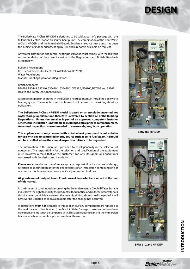
The BoilerMate A-Class HP-DEM is designed to be sold as part of a package with the Mitsubishi Electric Ecodan air source heat pump. The combination of the BoilerMate A-Class HP-DEM and the Mitsubishi Electric Ecodan air source heat pump has been the subject of independent testing by BRE and a report is available on request.
Any water distribution and central heating installation must comply with the relevant recommendation of the current version of the Regulations and British Standards listed below:-
Building RegulationsI.E.E. Requirements for Electrical Installations (BS7671)Water RegulationsManual Handling Operations Regulations
British StandardsBS6798, BS5449, BS5546, BS5440:1, BS5440:2, CP331:3, BS6700, BS7593 and BS7671.Health and Safety Document No 635
A competent person as stated in the Building Regulations must install the BoilerMate heating system. The manufacturer’s notes must not be taken as overriding statutory obligations.
The BoilerMate A-Class HP-DEM model is based on an Accolade unvented hot water storage appliance and therefore is covered by section G3 of the Building Regulations. Unless the installer is part of an approved competent installer scheme the installation is notifiable to Building Control prior to commencement. An annual inspection is recommended to ensure safe, long term operation.
This appliance must only be used with suitable heat pumps and is not suitable for use with any uncontrolled energy source such as solid fuel/steam. It should not be installed where the annual inspection is likely to be neglected.
The information in this manual is provided to assist generally in the selection of equipment. The responsibility for the selection and specification of the equipment must however remain that of the customer and any Designers or Consultants concerned with the design and installation.
Please note: We do not therefore accept any responsibility for matters of design, selection or specification or for the effectiveness of an installation containing one of our products unless we have been specifically requested to do so.
All goods are sold subject to our Conditions of Sale, which are set out at the rear of this manual.
In the interest of continuously improving the BoilerMate range, Gledhill Water Storage Ltd reserve the right to modify the product without notice, and in these circumstances this document, which is accurate at the time of printing, should be disregarded. It will however be updated as soon as possible after the change has occurred.
Modifications must not be made to this appliance. If any components are replaced in the field, they must be obtained from Gledhill Water Storage to ensure continued safe operation and must not be tampered with. This applies particularly to the immersion heaters which incorporate a pre-set overheat thermostat.
INTR
OD
UC
TIO
N
DESIGN
BMA 180 HP-DEM
BMA 210/240 HP-DEM

Page 6
DESIGNIN
TRO
DU
CTI
ON
Sealed primary system expansion/fillingcomponents available as an optional extra Figure 1.1
BoilerMate 180 HP-DEM
Zone 1 CH system (radiators or underfloor)Automaticbypass valve(if required)
CH zonevalve
CHboost3kW
HWSboost3kW
Secondary HWSreturn connection
HWS expansion vessel(s) supplied separatelywith the appliance for fitting on site
HWS outletHW zonevalve
T&Preliefvalve
Primaryrelief valve
Dischargepipe
MAV
S4
Manual air vent (MAV)
S3
Heatpump
IV
Dischargepipe
MCWSinlet
BalancedCWS outlet
Combinationvalve
S1/2
HP(primary)circulator
P1
S6
S5
Systemcirculator P2
IVIV
Externallymounted
temperaturecompensation
sensor
S7
BoilerBuddy
A BoilerMate A-Class HP-DEM is a floor standing packaged mains pressure unvented hot water appliance designed for use with the Mitsubishi Electric Ecodan air source heat pump. All models are factory fitted with all the necessary safety and control equipment for connecting to the domestic water systems, heat pump and the heating system as can be seen from figures 1.1, 1.2, 1.3 and 1.4.
The appliance has been specifically designed to maximise the efficiency of the heat pump and use the energy to provide improved space heating and mains pressure hot water performance.
The built in controls monitor the demands for heat ensuring that the low cost energy from the heat pump is used whenever possible and top up from the conventional heat source is only initiated when the flow temperature from the heat pump is not sufficient to meet the demands. The controls are set to provide hot water priority, ie. if there is a demand at S3, any heating demands will be suspended until the store temperature reaches the point where S3 is satisfied.
All models are designed to heat the domestic hot water indirectly up to the maximum temperature possible with the heat pump and then boost the temperature by means of a 3kW immersion heater up to the required set temperature. All models have connections for a zone 1 circuit where the central heating flow temperature can be boosted by means of an inline electric heater to the preset design temperature. However, the 210 and 240 models also have connections for a zone 2 circuit where no temperature boost is provided. This enables separate radiator and underfloor heating circuits to be provided, operating at
different design temperatures if required.
The BoilerMate A-Class HP-DEM is supplied with an outside temperature compensation sensor which needs to be mounted externally and wired back to the connection terminals provided in the appliance (using the 10m of cable provided). This will then automatically adjust the operation of both zone 1 and zone 2 heating circuits to take account of the external temperature and reduce the running costs.
8 metres of 8 core signal cable is also provided for connection between the BoilerMate A-Class HP-DEM appliance and the heat pump (see page 30 for details).
The most economical way of designing the heating systems is to utilise the temperature available from the heat pump itself. For this reason, underfloor/low temperature radiator systems should be chosen where possible. In these situations, the electric boost heater can be disabled at the control panel if required.

Page 7
DESIGN
INTR
OD
UC
TIO
N
Once installed and commissioned, the integration of all the heat pump, domestic hot water and central heating functions will be automatically controlled by the PCB built into the BoilerMate A-Class HP-DEM appliance. However, the temperature of the central heating will need to be controlled by remote room thermostat(s)/thermostatic radiator valves.
Details of how to enter this product in SAP are available. Please request a copy of the latest SAP Data Sheet which covers this and all other Gledhill Water Storage products.
In the event the heat pump fails, both the domestic hot water and central heating (partial only) can be heated using the built in electric heaters. This manual emergency heating mode can be selected by pressing the button labelled ‘switch’ on the appliance front panel for 5 seconds. Even in this mode the controls will give priority to the hot water. However, the appliance should only be operated in this mode for the short period of time required for the problem to be resolved.
The BoilerMate A-Class HP-DEM is designed to be sold as part of a package with the Mitsubishi Electric Ecodan air source heat pump. The combination of the BoilerMate A-Class HP-DEM and the Mitsubishi Electric Ecodan air source heat pump has been the subject of independent testing by BRE and a report is available on request. To allow a visual indication of system water quality and to protect the waterways of the heat pump from contamination a Fernox Boiler Buddy is provided as part of the package.
Scale Protection
The Building Regulations L1A: New dwellings/L1B: Existing dwellings and the requirements set out in the Domestic Heating Compliance Guide specify that “where the mains water hardness exceeds 200ppm provision should be made to treat the feed water to water heaters and the hot water circuit of combination boilers to reduce the rate of accumulation of lime scale”.
To comply with this requirement the hardness of the mains water should be checked by the installer and if necessary the optional factory fitted in-line scale inhibitor should be specified at the time of order for hardness levels between 200 and 300 ppm (mg/l).
Where the water is very hard ie 300ppm (mg/l) and above the optional polyphosphate type, inhibitor should be specified at the time of order. However, this will need to be fitted by the installer at a suitable point in the cold water supply to the appliance.
Sealed primary system expansion/fillingcomponents available as an optional extra Figure 1.2
BoilerMate 210/240 HP-DEM
Zone 1 CH system (radiators or underfloor)
Zone 2 CH system (underfloor or otherlow temperature heating system)
HP(primary)circulator
P1
S5 S6
CH zonevalve
CHboost3kW
HWSboost3kW
Secondary HWSreturn connection
HWS expansion vessel(s) supplied separatelywith the appliance for fitting on site
HWS outletHW zonevalve
T&Preliefvalve
Primaryrelief valve
Dischargepipe
MAV
S4
Manual air vent (MAV)
S3
IV
Systemcirculator P2
Zone 2 CHcirculator P3
BoilerBuddy
IVIV
IV
Dischargepipe
MCWSinlet
BalancedCWS outlet
Combinationvalve
S1/2
Externallymounted
temperaturecompensation
sensor
S7
IV
Heatpump
Automaticbypass valve(if required)

Page 8
DESIGNTE
CH
NIC
AL
DA
TA
180 modelFactory Fitted/Supplied Components
1 Domestic mains cold water inlet connection - see notes on page 12
2 Balanced pressure cold water outlet connection
3 Combination inlet control valve - unvented store
4 Pressure relief (safety) valve - primary system
5 Expansion vessel connection - unvented store
5a Expansion vessel - unvented store - see notes on page 12 & Figure 1.8
6 Pressure and temperature relief valve - unvented store
7 Tundish8 S5 sensor - heat pump return9 Expansion vessel connection - primary
system (Heat pump and heating circuit)10 Expansion vessel/gauge - primary system
- see notes on page 1211 Temporary filling loop - primary system
- see notes on page 1212 Drain valve13 Manual air vents - primary systems14 Central heating (Zone 1)/hot water
systems circulator (P2)15 D.H.W. zone valve (energy cut out)16 Central heating zone valve (Zone 1)17 Central heating flow connection (Zone 1)
- Isolating valve18 Central heating return connection (Zone 1)19 Flow connection (from heat pump)20 Heat pump system circulator (P1)21 Return connection (to heat pump)22 Discharge pipe connection23 S6 sensor - heat pump flow24 S4 sensor - central heating flow (+ boost)25 Electrical temperature boost assembly
- central heating (Zone 1 only)26 S3 sensor - hot water boost27 Primary system manifold28 Electrical temperature boost (hot water only)29 Flow to hot water coil - unvented system30 Return from hot water coil - unvented
store31 Domestic hot water outlet connection32 Secondary domestic hot water return
connection33 Electrical control panel/printed circuit
boards and connection terminals34 User control panel and 2 channel clock35 100mm high installation base36 8m 8 core signal cable to be site run/
connected to Mitsubishi HP by the installer37 S7 external temperature compensation
sensor and 10m of cable to be site run/fitted by installer
38 Fernox ‘Boiler Buddy’ in-line filter - see notes on page 12
Figure 1.3BoilerMate A-Class HP-DEM 180 model
6
13(front)
34
5 (mid)
33
13
15
28
29
2
3
1
35
31
7/22
2614
4
36
37
25
7/22
24
16
22
8
21
18 19
30
20
12
9(10/11)
17
27
23
32(rear)
Other Optional Equipment
• Hot and cold water manifolds for use with plastic pipework (Set 1 or 2).• Electronic scale inhibitor for mains water services with hardness levels above
200ppm (mg/l) fitted in the appliance.• Polyphosphate scale and corrosion inhibitor for mains water services with
hardness levels above 300ppm (mg/l) for fitting on site by the installer.

Page 9
210/240 modelsFactory Fitted/Supplied Components
1 Domestic mains cold water inlet connection - see notes on page 12
2 Balanced pressure cold water outlet connection
3 Combination inlet control valve - unvented store
4 Pressure relief (safety) valve - primary system5 Expansion vessel connection - unvented
store5a Expansion vessel - unvented store - see
notes on page 12 & Figure 1.86 Pressure and temperature relief valve
- unvented store7 Tundish8 S5 sensor - heat pump return9 Not used on this model10 Central heating return (Zone 2)
connection - expansion vessel/gauge - primary system - see notes on page 12
11 Temporary filling loop - primary system - see notes on page 12
12 Drain valve13 Manual air vents - primary systems14 Central heating (Zone 1)/hot water
systems circulator (P2)15 D.H.W. zone valve (energy cut out)16 Central heating zone valve (Zone 1)17 Central heating flow connection (Zone 1)
- Isolating valve18 Central heating return connection (Zone 1)19 Flow connection (from heat pump)20 Heat pump system circulator (P1)21 Return connection (to heat pump)22 Discharge pipe connection23 S6 sensor - heat pump flow24 S4 sensor - central heating flow (+ boost)25 Electrical temperature boost assembly
- central heating (Zone 1 only)26 S3 sensor - hot water boost27 Primary system manifold28 Electrical temperature boost (hot water only)29 Flow to hot water coil - unvented system30 Return from hot water coil - unvented store31 Domestic hot water outlet connection32 Secondary domestic hot water return
connection33 Electrical control panel/printed circuit
boards and connection terminals34 User control panel and 2 channel clock35 Central heating circulator (P3)(Zone 2)36 Central heating flow connection (Zone 2)37 S7 external temperature compensation
sensor and 10m of cable to be site run/fitted by installer
38 Fernox ‘Boiler Buddy’ in-line filter - see notes on page 12
39 100mm high installation base40 8m 8 core signal cable to be site run/
connected to Mitsubishi HP by the installer
Figure 1.4BoilerMate A-Class HP-DEM 210 & 240 models
6
13(front)
34
5 (mid)
33
13
15
28
29
35
36
12
2
3
1
39
31
7/22
2614
4
40
37
25
7/22
24
16
22
8
20
21
3010(11)
17
27
23
32(rear)
18 19
Other Optional Equipment
• Hot and cold water manifolds for use with plastic pipework (Set 1 or 2).• Electronic scale inhibitor for mains water services with hardness levels above
200ppm (mg/l) fitted in the appliance.• Polyphosphate scale and corrosion inhibitor for mains water services with
hardness levels above 300ppm (mg/l) for fitting on site by the installer.
DESIGN
TEC
HN
ICA
L D
ATA

Page 10
DESIGNTE
CH
NIC
AL
DA
TA
Figure 1.5
Either radiator orunderfloor heating circuit
Please note:This is a diagramatic representation,all pipework should enter through
base of appliance.All connections are 22mm.
Primary System Pipework Connections for BoilerMate A-Class HP 180 Model Only
Zone 1
flow
Zone 1
return
Water in(return)
Water out(flow)A
B
Ecodan(rear)

Page 11
DESIGN
TEC
HN
ICA
L D
ATA
Primary System Pipework Connections for BoilerMate A-Class HP 210 & 240 Models Only
Figure 1.6
Zone 1Either radiator or
underfloor heating circuit
Zone 2Underfloor or other low
temperature heating circuit
Zone 1
flow
Zone 2
flow
Zone 1
return
Zone 2
return
Please note:This is a diagramatic representation,all pipework should enter through
base of appliance.All connections are 22mm.
Ecodan(rear)
Water in(return)
Water out(flow)A
B

Page 12
10
5a
Notes:
Item 5a is supplied separately with the appliance (see Figure 1.8 and Table 1.1 below for details), complete with a fixing bracket and pipework installation kit.
Items 10 and 11 are available as an optional Primary Sealed System Kit at extra cost. If required, this should be ordered at the same time as the appliance (see Figure 1.7 and Table 1.1 below for details). The expansion vessels are provided with a suitable fixing bracket.
Item 38 is supplied separately with the appliance package for fitting internally in the heat pump return as near as possible to the heat pump, fully in accordance with the manufacturers instructions included later in this manual.
The appliance is available with the option of a factory fitted scale inhibitor, at extra cost. In this case the aerial is fitted on the 22mm cold inlet and the scale inhibitor PCB is fitted in the electrical panel/PCB area.
Figure 1.7 Figure 1.8
Primary system expansion vessel available as an optional extra at the time of order as part of the Primary
Sealed System kit
Unvented store expansion vessel supplied separately with the appliance
Expansion Vessels
ModelPrimary Expansion Vessel (Optional Extra) Unvented Store Expansion Vessel (Supplied)
Capacity (l) Size (mm) LxWxH Capacity (l) Size-each (mm) LxDiam
BMA 180 HP-DEM 12 500 x 200 x 160 12 270 x 270
BMA 210 HP-DEM 12 500 x 200 x 160 12 270 x 270
BMA 240 HP-DEM 2 x 12 500 x 200 x 160 18 400 x 270
Table 1.1
The size of the primary system expansion vessel has been calculated using typical design criteria for the maximum recommended heating load shown in Table 1.2. However, the
DESIGNTE
CH
NIC
AL
DA
TA
size should be checked and confirmed as being accurate by the system designer/installer.

Page 13
DESIGN
TEC
HN
ICA
L D
ATA
Technical Data
Model BMA 180 HP-DEM BMA 210 HP-DEM BMA 240 HP-DEM
Nominal domestic hot water storage volume (litres) 145 171 215
Overall app. dimensions (mm) (Height x Width x Depth) 1370 x 595 x 595 1600 x 595 x 595 1950 x 595 x 595
Minimum recommended cupboard dimensions (mm)
(Height x Width x Depth) 1970 x 700 x 600 (1) 2200 x 700 x 600 (1) 2250 x 700 x 700 (1)
Weight (kg) (Empty / Full) 87 / 232 103 / 274 114 / 329
Unvented store expansion vessel
Type: Varem 1 Off (2)
Total nominal volume (litres) 12 18
Charge pressure (bar) 1.5
Heat pump circuit circulating pump P1 Grundfos UPS 15-50
System circulating pump P2 (HW and Zone 1 CH) Grundfos UPS 15-50
Circulating pump P3 (Zone 2 CH) –––– Grundfos UPS 15-50
HW circuit zone valve - type Honeywell V4043 22mm
CH circuit zone valve - type Honeywell V4043 22mm
Electrical data
Supply: 230V AC, 50Hz rated at 6.5kW
Main supply circuit breaker 32A type B
Internal protection: Immersion heaters
2 x 16A MCBs (Type B)
Internal protection: Control circuit 1 x 6A MCB (Type B)
Internal protection: Heat pump L.V. control signal (12VDC signal)
1 x 100mA 20mm glass cartridge fuse (+ spare)
Control & overheat safety thermostat temperature settings
HW boost immersion heater S1/S2 safety sensors (3)
P & T valve 900C
CH boost immersion heater Control thermostat(5): 650C, Overheat thermostat(4): 850C
Control/relief valve pressure set points
Mains inlet pressure regulator 1.5 bar
Expansion relief valve (CW) 3.0 bar
Expansion relief valve (CH) 3.0 bar
P & T valve 4.0 bar
Maximum hot water flow rate 25-35
Dwelling type
Bedrooms 3-4 3-4 3-5
Bathrooms 1 1 2
En-suite 1 2 1
Maximum heating load 13kW
Electrical backup ‘switch’ 6kW
(1) The sizes shown allow for the unvented store expansion vessel to be fitted above the appliance in the case of the 180 and 210 models, but assume that the optional primary sealed system kit will be fitted elsewhere. The dimensions for the 240 model assume both the unvented store and primary expansion vessels will be fitted elsewhere due to the height of the appliance itself. Clear access 650 deep will be required in front of the whole of the appliance for future maintenance.(2) Supplied loose - To be fitted by installer in a suitably accessible location.(3) Temperature is automatically controlled by the controller sensors S1/S2.(4) Not adjustable - Manual reset type.(5) Temperature is automatically controlled by the controller sensor therefore should not be set lower than 650C.
Table 1.2

Page 14
Sensor Control Parameters & Default Temperature Settings
Description Sensor Default Value (0C)
HP off setting (flow) S6 58
HP off setting (return) S5 56
HP on-off differential setting S5/S6 3
HW store heating - off settingS3
60
HW store heating on-off differential setting 7
HW store overheat setting S1/S2 75 max.
Sensor S1/S2: Duplex domestic hot water overheat (store temp.)Sensor S6: Heat pump flow temperatureSensor S5: Heat pump return temperatureSensor S4: Central heating flow temperature (zone 1 circuit)Sensor S3: Domestic hot water temperature (store temperature)
HP: Heat pumpCH: Central heatingHW: Hot water heating
Notes: See Figure 1.3/1.4 for sensor locations.
Table 1.3
Model Selection Data
General guidance is given in Table 1.2.
When checking the suitability of the heat pump we recommend that the heat losses of the external building fabric plus half of the ventilation losses are directly compared to the Ecodan heat pump output of 9kW.
If design calculations are carried out in the normal way, using the method set out in BS5449. The Ecodan heat pump will cope with heating systems in which boiler sizes calculated in this way are rated at up to a maximum of 13kW.
As the BoilerMate A-Class HP-DEM is a hot water storage appliance, we recommend that the model size of the appliance is chosen by calculating the hot water volume in the normal way using the criteria set out in BS 6700 / NHBC for storage appliances.
Electricity Supply
One mains supply rated at 32A, 230V~, 50Hz is required.
Minimum external fuse rating and the main supply cable ratings are given in Table 1.2 Technical Data section of this manual. This appliance MUST BE EARTHED.
All external wiring to the appliance must be in accordance with the latest I.E.E. Wiring Regulation, and any local regulations which may apply.
The appliance shall be supplied from a suitably rated double pole isolator with a contact separation of at least 3mm in both poles.
This must be suitably labelled, provide complete electrical isolation and be within 1 metre of the BoilerMate A-Class HP-DEM Unit.
In the event of an electrical fault after installation of the appliance, preliminary electrical checks must be carried out i.e. Earth Continuity, Short Circuit, Polarity, and Resistance to Earth.
DESIGNTE
CH
NIC
AL
DA
TA
Appliance Location
The BoilerMate A-Class HP-DEM appliance must be installed on a flat surface which is capable of supporting the weight of the appliance and any other ancillary equipment. (The full weight must be used, see table 1.2 on page 13).
The appliance sizes and the minimum cupboard dimensions are shown in Table 1.2. A minimum of 600mm is required in front of the appliance for maintenance purposes. (See figures 1.3 and 1.4 on pages 8 and 9).
The appliance is designed to be installed on the timber plinth supplied with the appliance.
Details of the various electrical and pipework connections required are shown in Figures 1.3 and 1.4.

Page 15
DESIGN
TEC
HN
ICA
L D
ATA
180 Model Connection Details/Dimensions
Diagram opposite show the connection details and dimensions for the BoilerMate A-Class HP-DEM 180 model.
The BoilerMate A-Class HP-DEM units are supplied on an installation base to allow the pipe runs to connect to the appliance from any direction. It is easier if all pipes protrude vertically in the cut out area shown. Compression or push fit connections can be used. All pipe positions are approximate and subject to a tolerance of +/-20mm in any direction.
Note: All dimensions are shown in mm and are to the centre line of pipework/gland.
575
(595
incl
ud
ing
th
e d
oo
r/cl
ock
)
595
75
40
315
- DH
WS
Exp
an
sio
n
440
- Pri
ma
ry S
yste
m V
ent
300
545
180 Model Connection Details/Dimensions - Top
DHWS Secondary Return
Figure 1.9
575
(595
incl
ud
ing
th
e d
oo
r/cl
ock
)
440
- Hea
t Pu
mp
Ret
urn
440
- Hea
tin
g R
etu
rn (Z
on
e 1)
440
- Sea
led
Pri
ma
ry E
xp. V
esse
l
595
390
415
- Hea
tin
g F
low
(Zo
ne
1)
400
440
- Hea
t Pu
mp
Flo
w
470
- P&
T R
elie
f Va
lve
Dis
cha
rge
460
- Ho
t To
Ta
ps
430
450
540
495
- Co
ld In
270
60
90 105
180 Model Connection Details/Dimensions - Bottom
Expansion ReliefValve Discharge

Page 16
575
(595
incl
ud
ing
th
e d
oo
r/cl
ock
)
595
75
40
315
- DH
WS
Exp
an
sio
n
440
- Pri
ma
ry S
yste
m V
ent
300
545
210/240 Models Connection Details/Dimensions - Top
DHWS Secondary Return
Figure 1.10
575
(595
incl
ud
ing
th
e d
oo
r/cl
ock
)
440
- Hea
t Pu
mp
Ret
urn
440
- Hea
tin
g R
etu
rn (Z
on
e 1)
440
- Hea
tin
g R
etu
rn (Z
on
e 2)
595
390
440
- Hea
t Pu
mp
Flo
w
340
440
- Hea
tin
g F
low
(Zo
ne
2)
470
- P&
T R
elie
f Va
lve
Dis
cha
rge
460
- Ho
t To
Ta
ps
400
435
430
535
505
- Co
ld In
240
60
90 105
210/240 Models Connection Details/Dimensions - Bottom
415
- Hea
tin
g F
low
(Zo
ne
1)
Expansion ReliefValve Discharge
DESIGNTE
CH
NIC
AL
DA
TA
210/240 Model Connection Details/Dimensions
Diagram opposite show the connection details and dimensions for the BoilerMate A-Class HP-DEM 210/240 models.
The BoilerMate A-Class HP-DEM units are supplied on an installation base to allow the pipe runs to connect to the appliance from any direction. It is easier if all pipes protrude vertically in the cut out area shown. Compression or push fit connections can be used. All pipe positions are approximate and subject to a tolerance of +/-20mm in any direction.
Note: All dimensions are shown in mm and are to the centre line of pipework/gland.

Page 17
Hot and Cold Water System
All recommendations with regard to pipe work systems in this manual are generally based on the use of BS/EN Standard copper pipework and fittings.
However a plastic pipework system can be used in place of copper internally as long as the chosen system is recommended by the manufacturer for use in cold and hot water systems and is designed and installed fully in accordance with their recommendations.
It is also important that if an alternative pipework material/system is chosen, the manufacturer confirms that the design criteria for the new system is at least equivalent to the use of BS/EN Standard copper pipework and fittings or larger pipe sizes are considered.
In these appliances the mains inlet pressure regulating valve is set to 1.5 bar and this setting MUST NOT be adjusted. Therefore the flow rate from the appliance depends upon the resistance of the hot water supply network, capacity of the incoming mains and the characteristics of the pressure regulating valve
Mains Cold Water Supply
The BoilerMate A-Class HP-DEM appliance is designed to be connected directly to the mains. The combination inlet valve incorporates the required check valve. The hot water flow rate achievable is directly related to the adequacy of the cold water mains serving the property. For this reason the cold water supply to the dwelling must be capable of providing for those services which could be required simultaneously and this maximum demand should be calculated. Also if a water meter is fitted its nominal rating should match the anticipated maximum simultaneous hot and cold water demand calculated in accordance with BS 6700. This could be 60 litres per minute in some properties. 30 litres per minute is the minimum flow rate which is recommended for an adequate mains pressure system to any property.
The Building Regulations L1A: New dwellings/L1B: Existing dwellings and the requirements set out in the Domestic Heating Compliance Guide specify that “where the mains water hardness exceeds 200ppm provision should be made to treat the feed water to water heaters and the hot water circuit of combination boilers to reduce the rate of accumulation of lime scale”.
To comply with this requirement the hardness of the mains water should be checked by the installer and if necessary the optional factory fitted in-line scale inhibitor should be specified at the time of order for hardness levels between 200 and 300 ppm (mg/l).
Where the water is very hard ie 300ppm (mg/l) and above the optional polyphosphate type, inhibitor should be specified at the time of order. However, this will need to be fitted by the installer at a suitable point in the cold water supply to the appliance.
The combination valve fitted to the BoilerMate A-Class HP-DEM unit incorporates a pressure regulating valve set to provide a static operating pressure of 1.5 bar. On this basis there must be at least 2.0 bar pressure at the inlet to the appliance. This pressure must be dynamic (not static) and be available at the appliance when local demand is at its maximum. For optimum performance, and for larger properties, we would recommend that the dynamic pressure is in the range of 2.5 - 3.5 bar.
The combination valve also incorporates an expansion relief valve. The discharge from this can be connected into the discharge pipe from the P & T valve. Further details of how to treat this discharge are provided later in this manual.
As a general guideline, if a good pressure is available, a 15mm service may be sufficient for smaller dwellings with one bathroom. However a 22mm service (25mm MDPE) is recommended and should be the minimum for larger dwellings, or where only the minimum recommended pressure is available.
If the incoming mains pressure exceeds 6 bar at any time in a 24 hour cycle then a pressure regulating valve set at 3.5 bar should be fitted downstream of the stop tap where the cold supply enters the property.
Equipment used in the system should be suitable for a working pressure of up to 5 bar.
SYST
EM D
ETA
ILS
DESIGN

Page 18
Cold and Hot Water Distribution Network
a. As a minimum it is recommended that the cold supply to the appliance internally is run in 22mm copper (or equivalent in plastic) and then from the appliance, hot and cold services are in 22mm past the draw-off to the bath. For large properties bigger sizes will be necessary and these should be proved by calculation in accordance with BS6700. It is recommended that flow regulators are provided in the branch to each terminal fitting (or in the fitting itself ) to ensure best use is made of the available pressure/flow.
b. The highest hot or cold water draw-off point should not exceed 4 metres above the combination inlet valve fitted to the appliance.
c. In average size dwellings, the cold water supply to any mixer fittings (other than dual outlet fittings) should be taken from the balanced cold outlet connection on the combination valve fitted to the appliance. However, in larger dwellings with a number of bathrooms and en-suites and/or long pipe runs, the balanced cold supply must be provided with its own pressure regulating valve (set at the same pressure as the one provided with the appliance ie 1.5 bar static) and not taken from the appliance. When a separate pressure regulating valve is used for the balanced cold water supply, it is recommended that a small expansion vessel (0.25 - 0.5 litre) is fitted after the pressure regulator to accommodate the pressure rise caused by the increase in temperature of the balanced cold water.
SH WHB
SCV SCV
WC BATH
22
22
15
15
WHB WC
M
DC
DCV
DC
DCV
ToExternalTap
25mm MDPEIncomingSupply
WM or DWMSINK
DischargePipe
BoilerMateHP-DEM
GroundLevel
mai
ns
cold
ho
td
isch
arg
eb
alan
ced
co
ld
Locationof optional polyphosphatescale inhbitor- NOT REQUIRED unless the hardnesslevel exceeds 300ppm (mg/l)
Typical cold and hot water network (to a smaller property)
Cold supplies to single taps taken from the mains cold water system.Cold supplies to mixer taps only to be taken from the balanced cold water connection on the combination valve or in
larger property/minimum pressure situation from a separate pressure reducing valve.Figure 1.11
d. If the supply to the mixer fittings (other than a dual outlet type) is not taken from the balanced supply the system will become over pressurized and cause the pressure relief valve to discharge. Over time this could also cause the premature failure of the appliance itself which will not be covered by the warranty.
e. Whenever possible the hot and cold water supply to a shower-mixing valve should be the first draw-off point on each circuit.
f. It is important that the mains cold water pipe work is adequately separated from any heating/hot water pipe work to ensure that the water remains cold and of drinking water quality.
DESIGNSY
STEM
DET
AIL
S

Page 19
DESIGN
SYST
EM D
ETA
ILS
SH WHB
WHB
SCV
SINK
BATH
1
2
34
1. Bronze circulator2. Expansion Vessel3. Hot water return pipework4. Single check valve/non return valve - should be fitted as close as possible to the appliance
Manual/autoair vent
Schematic diagram of typical secondary hot water circulation
1. Hot flow and return pipework must be insulated2. All components must be suitable for use on domestic unvented hot water storage systems
Figure 1.12
BoilerMateHP-DEM
Taps and Shower Fittings
a. Ensure that all terminal fittings are suitable for mains pressure in the range of 0.5 - 1.5 bar. Use aerated taps whenever possible to prevent splashing.
b. Any type of shower mixing valve can be used as long as both the hot and cold supplies are mains fed. However, all mains pressure systems are subject to dynamic changes particularly when other hot and cold taps/showers are opened and closed, which will cause changes in the water temperature at mixed water outlets such as showers. For this reason and because these are now no more expensive than a manual shower we strongly recommend the use of thermostatic showers with this appliance.
The shower head provided must also be suitable for mains pressure supplies. If it is proposed to use a ‘whole body’ or similar shower with a number
of high flow/pressure outlets please discuss with the Gledhill technical department.
c. Note that the shower fittings must comply with the backflow prevention requirements (Para 15, Schedule 2) of the Water Supply Regulations.
d. A bidet can be supplied from the BoilerMate A-Class HP-DEM appliance as long as it is of the over rim flushing type and incorporates a suitable air gap.
Dead Leg Volumes and Secondary Hot Water Circulation
If the dead leg volume of the hot water draw-off pipework is excessive and the delivery time for hot water to be available at the tap is more than 60 seconds you may consider using:-
a. Trace heating such as the ‘Raychem HWAT’ system. Please call Gledhill technical department for further details.
OR
b. A secondary hot water circulation system as shown schematically in figure 1.9.

Page 20
Heat Pump/Space Heating System Design
General
Warning: BoilerMate A-Class HP-DEM is an unvented hot water storage appliance and therefore it is not suitable for use with a solid fuel boiler, steam or any other uncontrolled heat source.
The BoilerMate A-Class HP-DEM is designed to be sold as part of a package with the Mitsubishi Electric Ecodan air source heat pump. The combination of the BoilerMate A-Class HP-DEM and the Mitsubishi Electric Ecodan air source heat pump has been the subject of independent testing by BRE and a report is available on request.
The heating system design and installation must comply with the requirements of BS 6798 and BS 5449 for the performance parameters chosen for the system.
Plastic Pipework
All recommendations with regard to pipework systems in this manual are generally based on the use of BS/EN Standard copper pipework and fittings. However plastic pipework can be used in place of copper internally as long as it is recommended by the manufacturer and installed fully in accordance with their recommendations. Barrier type plastic pipework should always be used for these systems.
It is important to ensure that if the system is to be installed using plastic pipework it is designed and sized using the parameters for plastic pipework.
Selection/Heat Pump Sizing
General model selection guidance is given in Table 1.2 Technical Data.
Heat Pump Primary Circuit
The flow and return from the heat pump must run directly to the connections provided on the BoilerMate A-Class HP-DEM appliance.
A Fernox Boiler Buddy is provided as part of the package and this must be fitted internally on the return circuit as close as practical to the heat pump unit fully in accordance with the manufacturers instructions included later in this manual.
Central Heating Circuits
These should be sized in the normal way to suit the flow and return temperatures for the system chosen. The flow and return pipework should be connected directly to the connections provided.
If the heat pump/BoilerMate A-Class HP-DEM appliance is being fitted to an existing heating system, this must be thoroughly flushed/cleaned before the appliances are fitted.
Summer Towel Rail Circuit
If a separate summer towel rail circuit is required, this and the zone 1 CH circuit will need to be arranged as separate zones complete with their own time and temperature controls. Channel 2 on the clock provided on the appliance will then need setting to constant (continuous) operation mode. The wiring should be taken from the zone 1 room thermostat terminals. For further details, please contact the Gledhill Technical Helpline on 08449 310000.
DESIGNSY
STEM
DET
AIL
S

Page 21
DESIGN
SYST
EM D
ETA
ILS
Frost Protection The BoilerMate A-Class HP-DEM appliance should not be installed in a location where the contents could freeze. Suitable precautions should be taken to protect the heat pump/pipework as recommended in the heat pump section of this manual.
User Controls
A 2 channel digital programmer is fitted to the front of the appliance. A separate external room thermostat will normally be required for the central heating.
Heating System Bypass
Automatic bypass valves will be required in the heating systems if it is proposed to fit thermostatic radiator valves ( TRV’s) to all radiators or fit zone valves to control all the separate heating circuits. To meet the requirements of Building Regulations for a boiler interlock, it is recommended that the radiator in the area where the room thermostat is installed should be fitted with lock shield valves on both connections.
Appliance Primary Pipework/Coil Volumes
When calculating the total system volume, allow 10 litres for the primary pipework/coils within the appliance.
Sealed System kit For The Central Heating System
An optional sealed system kit as follows can be supplied with the BoilerMate A-Class HP-DEM.
• Pressure gauge (0 – 4 bar)• Primary expansion vessel charged to 1.0 bar,
(Size depends upon the model, see Table 1.1)• WRAS approved primary system filling
loop
External Temperature Compensation Sensor
This is supplied connected to 10 metres of cable which is coiled and cable tied to the pipework at high level in the appliance and will need to be mounted on an external wall and wired back to the BoilerMate A-Class HP-DEM appliance using the cable supplied. The sensor shall be located in a position which is not unduly affected by wind/direct sunlight etc. On this basis a sheltered location on a north facing wall is recommended.
Figure 1.13Boilermate A-Class HP-DEM 180 model
Heatingsystem
Dischargepipe
Heatpump
BoilerMate A-ClassHP-DEM
Sealed primarysystem filling/expansion kit
(optional extra)
Note: With the 210/240 models, the sealed primary system filling/expansion kit will need to be connected to the Zone 2 return connection or branched into the return pipework.

Page 22
Front Panel User Controls
The front panel user controls are shown in the picture opposite and their functions are described below.
Different windows can be accessed in the visual display panel on the front of the appliance to indicate various temperatures and fault conditions.
2 Channel Clock
A 2 channel Grasslin clock is provided to allow separate control of the hot water and heating requirements in accordance with the latest Building Regulations. Details of how to set the clock are provided on the User label and in the User Instructions.
Channel 1 controls the operating times for the domestic hot water heating circuit. This should normally be set to constant to allow the hot water to be available 24 hours a day.
Channel 2 controls the operating times for the zone 1 central heating circuit and should be set to suit the householders lifestyle.
Note: Electrical connections are provided on the terminal strip for a room thermostat. With the two larger models, separate time and temperature controls such as a remote programmable room thermostat will be required for the zone 2 central heating circuit. Electrical connections are also provided for this on the terminal strip.
Normal Operating Display Window
In normal automatic heat pump operation the display will be as shown opposite.
Switch Operating Display Window
If a fault occurs with the heat pump, the ‘Switch’ emergency electric back-up system can be selected by pressing and holding the ’Switch’ button below the display for at least 5 seconds. The ‘Normal’ will change to ‘Switch’ and will flash.
Once the problem has been resolved, the appliance can be returned to normal operation by pressing the ‘Switch’ button for at least 5 seconds.
Fault Condition Display Window
If a fault occurs with the BoilerMate A-Class HP-DEM appliance the window will automatically display the fault condition. The window will flash alternately between the two displays shown opposite.
The first window shows the fault reference code.
The second window shows a description of the actual fault condition.
Control/Status Display Window
By pressing the select button once when the window is in the normal operating mode, the current temperatures and the status of the sensors/pumps can be seen as shown typically opposite - also see Table 1.3 on page 12.
By pressing the select button twice, the set point values that are being used can be seen as shown opposite.
Control Circuit Power Switch
This switch only controls the supply to the appliance control circuit. For service the appliance must be isolated at the appropriate 2-pole isolator fitted adjacent to the appliance.
Normal operating display
Boilermate-HP-DEM
Mode: Normal
Switch operating display
Boilermate-HP-DEM
Mode: Switch
Fault condition display
Boilermate-HP-DEM
Model: Fault 10
Fault condition display
Boilermate-HP-DEM
Sensor Fault
S1S2S3S4
54545735
S5S6S7CH-IH
384814
P1P2P3HW-IH
Control/sensor status display - current
Control/status display - set points
DESIGNSY
STEM
DET
AIL
S
HPST1F1R
385856
2F2RTDDE
4535360
H1H2HLHW
50HBY453560WBY
Reset Select ControlCircuit Switch
2 ChannelClock
Visual DisplayWindow
Switch

Page 23
SYST
EM D
ETA
ILS
DESIGN
Main Appliance Control Board
By pressing S1 and S2 on the main appliance control board, the LED display can be used to read various values as shown below.
However, fault conditions are displayed on the front user panel and normally this board should only need to be used to display the sensor conditions or select the appliance type if the board needs to be changed.
If any problems are experienced with this, assistance will be provided by ringing the Gledhill Technical Helpline 08449 310000.
APPLIANCE CONTROL BOARD (A.C.B)
Fuse
T3.
15L
250V
2 DIGIT ACB BOARD DISPLAY FLOW CHART
Press S2
Press S2
Press S2
Press S2
Press S2
S2 S1
Press
S1
Press
S1
Press
S1
Press
S1Appliance
type
Press
S1
Press
S1
Press
S1
Press
S1Appliance
type
Press
S1
Press
S1
Press
S1
Press
S1Fault code indicator
block outs
Press
S1
Press
S1
Press
S1
Press
S1Fault code indicator
lock outs
Press
S1
Press
S1
Press
S1
Press
S1Control set-point
reading
Press
S1
Press
S1
Press
S1
Press
S1Sensor temperature
reading
Normal - standby stateIndicate system status
S2 S1
2 digitdisplay
2 pushbuttons
Mainprocessor

Page 24
Discharge Arrangements
The Pressure and Temperature Relief Valve (P&T) and Expansion Relief Valve (ERV) are both provided with tundishes. It is normal for these to be connected into a single 22mm discharge pipe but they can be run separately if required. At least the first 300mm of pipework below the tundish should be vertical and not contain any elbows/bends to ensure that if a fault occurs, the water does not back up and discharge from the tundish. All elbows/bends should be large radius wherever possible.
The discharge from the P&T valve under a fault condition will be above 90°C. Because of this, it is a requirement of Building Regulation Approved Document G3 that the discharge from an unvented hot water storage system is conveyed to where it is visible but will not cause danger to persons in or about the building. The discharge pipe from the appliance tundish should be fitted in accordance with these requirements.
The discharge pipe MUST terminate in a SAFE and VISIBLE position. For a 22mm discharge it must have an equivalent length of no more than 9 metres and it must have a continuous fall (1:200 minimum) throughout its length. Above 9 metres equivalent length, the pipe diameter must increase to meet the requirements of the table shown opposite.
An example of how to calculate the size required is as follows:A G½ temperature relief valve has a discharge pipe with 4 elbows and length of 7m from the tundish to the point of discharge. From the table opposite, maximum resistance allowed for a straight length of 22mm copper discharge pipe from a G½ temperature relief valve is 9.0m. Subtract the resistance for 4 No. 22mm elbows at 0.8m each = 3.2m. Therefore the maximum permitted length equates to 5.8m. 5.8m is less than the actual length of 7m therefore calculate the next largest size. Maximum resistance allowed for a straight length of 28mm pipe from a G½ temperature relief valve equates to 18m. Subtract the resistance for 4 No. 28 elbows at 1.0m each = 4m. Therefore the maximum permitted length equates to 14m. As the actual length is 7m, a 28mm copper pipe will be satisfactory.
In apartment/flat situations the discharge pipes can be connected into a single pipe which is discharged at low level. In this case the number should be limited to 6 to allow the fault to be easily traced. The single pipe should be at least one size larger than the largest individual discharge pipe connected to it.
The discharge can consist of scalding water and steam therefore the pipework should be metal. The following locations for the discharge pipe are acceptable:
Low Level
• Into a gully below the grating but above the water level (see diagram 1).• Onto the ground (drive, path or garden area). The pipe should discharge downwards
and be no more than 100mm above ground level. A wire cage should be provided to prevent people coming into contact with scalding water (see diagram 2).
High Level
High level discharge is only acceptable if it is :• onto a flat or pitched roof capable of withstanding high temperature water and
at least 3m away from plastic guttering. or• into a metal hopper and down pipe which terminates at low level (as described above.)
Discharge into a soil or waste pipe (whether plastic or metal) is not acceptable.
The proposals for the discharge pipe/termination point should be discussed and agreed with the Building Control Officer prior to commencing any work.
Further details are given in approved Document G3 of the Building Regulations.Diagram 2
Discharge onto the ground
Diagram 1Discharge into a gully
SYST
EM D
ETA
ILS
DESIGN
Sizing of Discharge Pipe From Safety/Temperature Relief Valve Tundish
Valve outlet
size
Min size of
discharge pipe from
tundish
Maximum resistance
allowed shown as straight
pipe length
Resistance created by each
elbow or bend
G½
22mm < 9m 0.8m
28mm < 18m 1.0m
35mm < 27m 1.4m

Page 25
INSTALLATION
SITE
REQ
UIR
EMEN
TS
The appliance is designed to be installed in an airing/cylinder cupboard and the relevant minimum dimensions are provided in Table 1.2 Technical Data.
Because of the ease of installation we recommend that the cupboard construction is completed and painted before installation of the appliance. The cupboard door can be fitted after installation.
If the unit needs to be stored prior to installation it should be stored upright in a dry environment and on a level base/floor.
Installation and maintenance access is needed to the front and top of the appliance. See Table 1.2 Technical Data for further details.
The minimum dimensions contained in Table 1.2 Technical Data allow for the passage/connection of pipes to the appliance from any direction as long as the appliance is installed on the installation base provided. If the installation base is not used extra space may be needed to allow connection to the pipework and the whole of the base area should be continuously supported on a material which will not easily deteriorate if exposed to moisture.
The floor of the cupboard needs to be level and even and capable of supporting the weight of the appliance when full. Details of the weight when full is provided in Table 1.2 Technical Data.
The appliance is designed to operate as quietly as practicable. However, some noise (from pumps etc) is inevitable in any heating system. This will be most noticeable in cupboards formed on bulkheads, or at the mid span of a suspended floor. In these cases the situation can be improved by placing the appliance on a suitable sound deadening material (i.e. carpet underlay or similar).
The appliance is very well insulated and no ventilation is normally required to the cupboard.
A suitable location will be needed for the unvented store expansion vessels. This will often be on top of the appliance itself or at high level in the cupboard housing the BoilerMate A-Class HP-DEM appliance. The dimensions and clearances are shown in section 1.2 Technical Data. A location is also required for the primary system expansion vessel as well as a suitable route for the connecting pipe from the BoilerMate A-Class HP-DEM appliance to the expansion vessel. A suitable route and discharge location will also be required for the discharge pipe from the P & T valve and ERV for all models.
An electrical supply must be available which is correctly earthed, polarized and in accordance with the latest edition of the IEE requirements for electrical Installations BS 7671.
The electrical mains supply needs to be 230V AC/50Hz/Single Phase.
Connection must be made using a double-pole linked isolator with a contact separation of 3mm in both poles which is located within 1m of the appliance. The supply must only serve the appliance.
The supply to all models shall be rated at 32 amp.

Page 26
Preparation/placing The Appliance In Position
Details of the recommended positions for termination of the first fix pipework are provided in figures 1.5 and 1.6. The pipework can be located or its position checked using the template provided with each appliance. If these have been followed, installation is very simple and much quicker than any other system. The appliance is supplied shrink wrapped on a timber installation base. Carrying handles are also provided in the back of the casing.
If the optional primary sealed system kit is ordered this will be supplied in a separate box. It is the installers responsibility to check that the size of expansion vessel provided is adequate for the primary/heating system being installed.
The appliance should be handled carefully to avoid damage and the recommended method is shown opposite. Further details are provided on page 4 and Appendix D of these instructions. Before installation the site requirements should be checked and confirmed as acceptable. The plastic cover and protective wrapping should be removed from the appliance and the installation base (provided) placed in position.
The appliance can be then be lifted into position in the cupboard on top of the base and the front panel removed by unscrewing the 2 screws and lifting the door up and out ready for connection of the pipework and electrical supplies. If they are not being fitted on top of the appliance a suitable support shall be installed for the unvented store expansion vessels.
The primary sealed system filling/expansion kit should be fitted on the supports provided and piped to the connection point provided on the BoilerMate A-Class HP-DEM appliance complete with a manual air vent at the high point.
HANDLINGWhen lifting the unit work with someone of similar build and height if possible.
Choose one person to call the signals.Lift from the hips at the same time, then raise the unit to the desired level.
Move smoothly in unison.Larger units may need team lift
INSTALLATIONIN
STA
LLA
TIO
N

Page 27
INST
ALL
ATI
ON
INSTALLATION
MC
B 2
MC
B 1
MC
B 3
16A 6A16A
NZ1
RSL
Z1
RSSL
Z1
RSN
Z2
RSL
Z2
RSSL
Z2
RSN
Z2
RSE
V1
L
V2
L
V
N
Z1
RSE
V
EL1 L2 L3
BUS BAR
10 / 6 mm
Sup
ply C
able
230V 50Hz AC32 amp supply from adouble pole isolator
located within 1 metreof the appliance
Room thermostat (Zone 1)
Blk Br
13 2
Bl G/Y
Remove linkto wire roomthermostat
Use to connect theCH zone 2 time and
temperature controlsto the BoilerMateA-Class HP-DEM
appliance
L
Electrical Connection - Appliance
All the power and control functions of the BoilerMate A-Class HP-DEM are pre-wired to a terminal strip located at high level inside the appliance. The wiring to the appliance shall be carried out by a competent person in accordance with the Building Regulations (Approved Document P) and the IEE Requirements for Electrical Installations BS 7671. Details of the necessary wiring are shown opposite and on the electrical schematic drawing (see pages 26 and 27).
All the terminals are suitably labelled on the appliance.
Note: Do not attempt the electrical work unless you are competent to carry it out to the above standards.
Before commencing check that the power source is in accordance with the Site Requirements and ensure that it is isolated.
The heat pump wiring instructions (Appendix A) should be read in conjunction with this manual.
Run the external wiring through the service slot provided in the base of the appliance.
Make the connections as shown opposite on the terminal strip provided.
The room thermostat should be wired as shown opposite. The link in Z1RSL to Z1RSSL must be removed when the room thermostat is fitted.
The time and temperature controls for CH zone 2 should be wired as necessary into the Z2 terminals provided.
Before switching on the electrical supply check all the factory made terminal connections to ensure they have not become loose during transit.
Frost/Building Fabric Protection
When frost protection is required for the whole house set channel 2 of the clock to constant during the time required and adjust the room thermostat to a suitable setting.
Electricians/Installers Please Note
The 2 x 16A MCB’s (MCB1 and MCB2) for the central heating and hot water electric boost heaters are supplied set in the ‘OFF’ position by an adhesive warning label. MCB3 is supplied set in the ‘ON’ position. The heat pump/primary systems can be commissioned with the switches in these positions and MCB1 and MCB2 must not be switched on before the heat pump/primary systems have been fully tested/commissioned.
After these have been commissioned, move MCB1 and MCB2 to the ‘ON’ position which will break the warning label and then commission the electric boost facility. Ensure that all air has been vented from the primary system before doing this.
IMPORTANT

Page 28
‘A’ Class Boilermate HP-DEM issue 4.ai
Bl
BlBl
Bl
RR
R
R
Br
Br
Y
Br
BrBr
Y
B
Y
B
G
Wh
Wh
Wh
B
BLBr
Bl
Bl
Bl
Br
Br
Br
B
B
B
Br
G/Y
G/Y
G/Y
R
OO
BB
YY
S4
S3
S1 & S2
J33
J32
J28
J29
J3
LL
LN
NN
EE
EM
MM
* All wire sizes 0.5mm² unless otherwise stated
Y
(1) Connection only usedif Modulating Pump is fitted
(1)
(CH Zone 1 Electric Boost)
(How Water Electric Boost)(Heating SL-H)
(Hot Water SL-W)
(Comfort Cooling call SL-C)
(Room Stat SL-R)
CH Z2Pump
SystemPump
Heat PumpPump
Bl
Br Br
Green Neon IlluminatedON / OFF Switch
1b
1a 1
O I
1a 1b1Rocker Switchterminalconections
HW Valve
BA
NormallyClosed
3Speed
3Speed
BrBr
OO
Br
Wh
S5
S6
Br
Wh
R
BlueBlBrownBr
GreenGreyGreen / Yellow
GGrG/Y
WIRE COLOUR LEGEND
BlackOrangeYellowWhite
Red
BOrY
Wh
R
S 3
S 4S 5S 6
Hot Water overheat sensors
Hot Water Control sensor
Zone 1 CH Flow Sensor
Heat Pump Return sensor
Outside Temperature Sensor
Heat Pump Flow sensor
S1/S2
SENSOR LEGEND
S 7
3Speed
Multicore Signal Cabel to Mitsubishi Air Source Heat Pump Terminals.
P2
P1
P3
Com
N/O
R
N/C
Bl
(Hot Water Valve V1)
(CH Zone 1 Valve V2)
G/Y
Or
Wh
Bl
J34
J5
J30
J31J9
(1)
Br Br Br
MC
B 2
MC
B 1
MC
B 3
16A 6A16A
Mains Supply230VAC 50Hz 32Amps
6.0 / 10.0mm² Twin & Earth Cable PVC(10.0mm² is only required when there is a high
ambiant temperature and/or long cable run)
N
L NE
CH1HOT WATER
CH2CH ZONE 1
TWO CHANNEL DIGITAL CLOCK
1 2 3 64 5 7
M~
8
147MP_34
147DI_2
147-HP
S7OutsideTemperatureSensor
Wh
Z1RSL
Z1RSSL
Z1RSN
Z2RSL
Z2RSSL
Z2RSN
Z2RSE
V1L
V2L
VN
VS2
OWC
OWC
HPA1
HPA2
HPA3
HPA4
HPA5
HPB1
HPB2
HPB3
FUSE
OWC
Wh
A1
B1
A5
A4
A3
A2
B2
B3
100mA@12 VDC20mmFuse
A2 A1
HW
-B
CH
-Z1-
B3kW
Room thermostatcall for Zone 1 Only
Programmable Room thermostatcall for Zone 2 Only
Z1RSE
VS1
2.5 mm SID Silicone
2
3kW
3 WAY BUS BAR
2.5 mm SID Silicone
2
Remove linkto wire roomthermostat
Br
B
F1
14
11
12
R1 CC
31 2 87654
A
B
C
D
E
DRG. NAMEDRG. SIZE
JOB NAMETITLE
'A' Class BoilerMateHeatpump HP-DEM
Electrical Schematic for :‘A’ Class BoilerMate Heatpump HP-DEM
ISSUE No : 4
APPROVED
DATE : NOV 2007
A3
GLEDHILL WATER STORAGE LTD.
DO NOT SCALE FROM THIS DRAWING. COPYRIGHT OF THIS DRAWINGIS RESERVED. IT IS NOT TO BE REPRODUCED COPIED OR DISCLOSEDTO A THIRD PARTY EITHER WHOLLY OR IN PART WITHOUT OURWRITTEN CONSENT.© GLEDHILL WATER STORAGE LTD.
SYCAMORE TRADING ESTATESQUIRES GATE LANEBLACKPOOLLANCASHIREFY4 3RL
DRN. SIGN. DATE DATEAPP'D.CH'KD.DATE
06-11-07 06-11-0706-11-07S. McGachie S. GataoraS. Gataroa
CH Valve
BA
NormallyClosed Z1
SIGN.
V2 V1
VE
2.5 mm SID Silicone 2
C2
A1
A2
2 4
1 3
J5 J4 J3
J7 J11 J8 J10
J2 J1
T1K1K2K3K3
S1
ON
C2
ISO1ISO2 C1J6
C1
A1
A2
2 4
1 3
L1 L2
2.5 mm SID Silicone 2
L3
2.5 mm SID Silicone 2
BrBl N
L
2 3 41
ON
SPD1/2A
OPTIONAL EXTRA IF FITTED, THISAREIAL IS WRAPPEDAROUND THE COLDWATER MAINS FEED
PART No. XB142
INSTALLATIONW
IRIN
G D
IAG
RA
M

Page 29
‘A’ Class Boilermate HP-DEM issue 4.ai
Bl
BlBl
Bl
RR
R
R
Br
Br
Y
Br
BrBr
Y
B
Y
B
G
Wh
Wh
Wh
B
BLBr
Bl
Bl
Bl
Br
Br
Br
B
B
B
Br
G/Y
G/Y
G/Y
R
OO
BB
YY
S4
S3
S1 & S2
J33
J32
J28
J29
J3
LL
LN
NN
EE
EM
MM
* All wire sizes 0.5mm² unless otherwise stated
Y
(1) Connection only usedif Modulating Pump is fitted
(1)
(CH Zone 1 Electric Boost)
(How Water Electric Boost)(Heating SL-H)
(Hot Water SL-W)
(Comfort Cooling call SL-C)
(Room Stat SL-R)
CH Z2Pump
SystemPump
Heat PumpPump
Bl
Br Br
Green Neon IlluminatedON / OFF Switch
1b
1a 1
O I
1a 1b1Rocker Switchterminalconections
HW Valve
BA
NormallyClosed
3Speed
3Speed
BrBr
OO
Br
Wh
S5
S6
Br
Wh
R
BlueBlBrownBr
GreenGreyGreen / Yellow
GGrG/Y
WIRE COLOUR LEGEND
BlackOrangeYellowWhite
Red
BOrY
Wh
R
S 3
S 4S 5S 6
Hot Water overheat sensors
Hot Water Control sensor
Zone 1 CH Flow Sensor
Heat Pump Return sensor
Outside Temperature Sensor
Heat Pump Flow sensor
S1/S2
SENSOR LEGEND
S 7
3Speed
Multicore Signal Cabel to Mitsubishi Air Source Heat Pump Terminals.
P2
P1
P3
Com
N/O
R
N/C
Bl
(Hot Water Valve V1)
(CH Zone 1 Valve V2)
G/Y
Or
Wh
Bl
J34
J5
J30
J31J9
(1)
Br Br Br
MC
B 2
MC
B 1
MC
B 3
16A 6A16A
Mains Supply230VAC 50Hz 32Amps
6.0 / 10.0mm² Twin & Earth Cable PVC(10.0mm² is only required when there is a high
ambiant temperature and/or long cable run)
N
L NE
CH1HOT WATER
CH2CH ZONE 1
TWO CHANNEL DIGITAL CLOCK
1 2 3 64 5 7
M~
8
147MP_34
147DI_2
147-HP
S7OutsideTemperatureSensor
Wh
Z1RSL
Z1RSSL
Z1RSN
Z2RSL
Z2RSSL
Z2RSN
Z2RSE
V1L
V2L
VN
VS2
OWC
OWC
HPA1
HPA2
HPA3
HPA4
HPA5
HPB1
HPB2
HPB3
FUSE
OWC
Wh
A1
B1
A5
A4
A3
A2
B2
B3
100mA@12 VDC20mmFuse
A2 A1
HW
-B
CH
-Z1-
B3kW
Room thermostatcall for Zone 1 Only
Programmable Room thermostatcall for Zone 2 Only
Z1RSE
VS1
2.5 mm SID Silicone
2
3kW
3 WAY BUS BAR
2.5 mm SID Silicone
2
Remove linkto wire roomthermostat
Br
B
F1
14
11
12
R1 CC
31 2 87654
A
B
C
D
E
DRG. NAMEDRG. SIZE
JOB NAMETITLE
'A' Class BoilerMateHeatpump HP-DEM
Electrical Schematic for :‘A’ Class BoilerMate Heatpump HP-DEM
ISSUE No : 4
APPROVED
DATE : NOV 2007
A3
GLEDHILL WATER STORAGE LTD.
DO NOT SCALE FROM THIS DRAWING. COPYRIGHT OF THIS DRAWINGIS RESERVED. IT IS NOT TO BE REPRODUCED COPIED OR DISCLOSEDTO A THIRD PARTY EITHER WHOLLY OR IN PART WITHOUT OURWRITTEN CONSENT.© GLEDHILL WATER STORAGE LTD.
SYCAMORE TRADING ESTATESQUIRES GATE LANEBLACKPOOLLANCASHIREFY4 3RL
DRN. SIGN. DATE DATEAPP'D.CH'KD.DATE
06-11-07 06-11-0706-11-07S. McGachie S. GataoraS. Gataroa
CH Valve
BA
NormallyClosed Z1
SIGN.
V2 V1
VE
2.5 mm SID Silicone 2
C2
A1
A2
2 4
1 3
J5 J4 J3
J7 J11 J8 J10
J2 J1
T1K1K2K3K3
S1
ON
C2
ISO1ISO2 C1J6
C1
A1
A2
2 4
1 3
L1 L2
2.5 mm SID Silicone 2
L3
2.5 mm SID Silicone 2
BrBl N
L
2 3 41
ON
SPD1/2A
OPTIONAL EXTRA IF FITTED, THISAREIAL IS WRAPPEDAROUND THE COLDWATER MAINS FEED
PART No. XB142
WIR
ING
DIA
GR
AM
INSTALLATION

Page 30
WIR
ING
DIA
GR
AM
INSTALLATION
BoilerMate A-Class HP-DEM(internal)
8 coresignal cable
ExternalInternal
Mitsubishi Air Source Heat Pump(external)
A1
A2
A3
A4
A5
B1
B2
B3
OWC
OWC
Brown
Red
Black
Yellow
Green
Blue
Violet
White
White
White
A1
A2
A3
A4
A5
B1
B2
B3
ModulationSignal
Outside WeatherCompensation Sensor S7
12V/24VSupply
StatusSignals
Comfort Cooling
Electrical Interconnections Between BoilerMate A-Class HP-DEM and Mitsubishi Electric Ecodan air source heat pump.
8 metres of 8 core signal cable is provided pre-terminated and labeled ready to connect to the Gledhill BoilerMate A-Class HP-DEM appliance as shown on page 28. This will require to be site run and connected to the heat pump by the installer as shown.
If any additional length is required, please use RS Components: stock code 482 6036 (25 metres) and replace the entire length, DO NOT JOINT. Maximum length is 30 metres. If using alternative cable to the above, the individual cores must be a minimum of 0.5mm2.
External Temperature Compensation Sensor
This is supplied connected to 10 metres of cable which is coiled and cable tied to the pipework at high level in the appliance and will need to be mounted on an external wall and wired back to the BoilerMate A-Class HP-DEM appliance using the cable supplied. The sensor shall be located in a position which is not unduly affected by wind/direct sunlight etc. On this basis a sheltered location on a north facing wall is recommended.
Warning
When connecting the cable to the external temperature compensation sensor, ensure the cable inlet is facing down.
1 2
1 2 3

Page 31
CO
MM
ISSI
ON
ING
INSTALLATION
System Filling/Cleansing
Check and adjust as necessary the hot water system expansion vessel(s) air pressure to 1.5 bar.
Check that any drain valves are closed then open the incoming stop valve and fill the domestic mains cold and hot water systems in the normal way ensuring there is no air trapped in the system.
Check and adjust as necessary the primary heating system expansion vessel to the figure specified (normally 1.0 bar).
Note: The expansion vessel pressures should be checked before the systems are filled.
Fill the primary heating system with potable water through the filling loop provided to the pressure required (normally 1.0 bar).
During filling vent air as necessary from the high points of the system including the manual air vents provided on the appliance and on the feed to the expansion vessel.
Check the whole of the primary heating and domestic hot and cold distribution systems for leaks.
It is essential that all systems functions properly for optimum performance.
To achieve this, the primary system should be commissioned in accordance with good practice and generally in accordance with the requirements of BS 6798, BS 5449 and BS 7593.
When using either cleansing or corrosion inhibitor chemical, the manufacturers instructions must be followed.
Cleansing the Primary System
It is very important to ensure that the Primary system is cleaned using a suitable cleansing agent such as Fernox F3 to ensure that any flux residues/installation debris are removed. The cleaning should be carried out fully in accordance with the manufacturers instructions. To allow thorough flushing, full bore drain valves should be provided.
Primary Water System Treatment
Although the BoilerMate A-Class HP-DEM has no special water treatment requirements, the radiators and other parts of the circuit will require the application of a scale and corrosion inhibitor. The heat pump and external connecting pipework will also require protection against freezing. For this reason a combined anti freeze and inhibitor product such as Fernox Alphi 11 must be used.
The volumes/concentration should be calculated in accordance with the manufacturers instructions allowing 10 litres for the volume for the primary pipework/coil in the BoilerMate A-Class HP appliance.
We consider that in typical radiator systems, the total water volume will not exceed 80 litres. On this basis, 20 litres of Alphi-11 will provide at least the 25% concentration recommended by the manufacturer as the minimum. However, because of the volumes experienced in underfloor system, the system volume for these types of systems will need to be calculated.
The Fernox Boiler Buddy supplied separately with the appliance package should be installed internally on the heat pump return as near as practical to the heat pump - see page 48 for further details.
Powerflushing/Cleaning Of The Heating System
If it is proposed to ‘powerflush’ the heating system always check and comply fully with the manufacturers instructions for the powerflushing equipment being used.
It is recommended that the heat pump and the BoilerMate A-Class HP appliance is bypassed during powerflushing of the primary/heating system.
If in any doubt please consult our Technical Helpline.
Cleansing the Hot/Cold Water System
Fully flush and, when necessary, chlorinate the hot and cold water system in accordance with the recommendations in the Model Water Byelaws and BS 6700.
Remove and clean the strainer element in the combination inlet valve, then replace it and re-fill the systems.
Once the systems have been refilled manually open the relief valves one by one and check that water is discharged and runs freely through the tundish and out at the discharge point. The pipework should accept full bore discharge without overflowing at the tundish, and the valve should seat satisfactorily.
On completion, check the pressure in the primary system is correct and disconnect the manual filling loop.

Page 32
Appliance Commissioning
The built in controls should ensure compatibility if the heat pump and the BoilerMate A-Class HP-DEM appliance. They will automatically control the two appliances once both appliances are energised.
Turn on the BoilerMate A-Class HP-DEM and check that the sensors and all controls operate correctly as well as any motorised valves. Check that no water discharges from either the expansion valve or temperature and pressure-relief valve during the heating cycle.
Do not switch on MCB1 and MCB2 to activate the CH and DHWS electric boost systems until the primary systems have been commissioned.
Check the appliance, the heating system and hot water system for leaks when hot.
System Commissioning
Check that the correct outlet pressure is being maintained on the domestic water systems by the pressure reducing valve by checking the pressure at a hot tap or in the tapping provided on the combination inlet valve.
Check the correct flow is being achieved at each tap and the implications of opening more than one tap at the same time. If necessary fit flow regulators to each tap if these have not already been provided.
The heating systems and pumps should be set and balanced in the normal way to provide the temperature differential in line with the system design parameters chosen.
The primary system and pump to the heat pump should normally be set to speed 3.
If an automatic bypass valve is provided on the primary/heating circuit, check/adjust this as necessary to suit the particular installation requirements.
The room thermostat/clock or programmable room thermostat controls the heating and hot water systems and should be set to suit the householders requirements using the instructions provided with the controls.
This product is covered by the ‘Benchmark’ scheme and a separate commissioning/service log book is included with this product. This must be completed during commissioning and left with the product to meet the Warranty conditions offered by Gledhill.
On completion:-
1. Do ensure that the electrical connections (e.g. mains supply, room thermostat) to the unit are correct and tight.
2. Do ensure that all the pipework connections in the appliance are tight and not leaking.
3. Do ensure that any pipework particularly plastic adjacent to the appliance is adequately supported and anchored.
4. Do ensure that the functioning and control of the system is explained to the occupant and explain the need and importance of periodic servicing.
These Instructions should be replaced along with the component manufacturers instructions in the pocket provided on the appliance and the front panel refitted.
NOTE:- With sealed heating systems air is released from the water during the first few weeks of operation. This must be vented and the system repressurised.
If the system is not likely to be used continuously after testing/commissioning it should be isolated from the water and electricity supply and either drained down or have the pressure removed from both the heating and water systems.
Important Do’s and Don’ts
DO check the incoming mains water pressure and flow rate are adequate. (The preferred range of mains pressure is 2.5-3.5 bar).
DO check and ensure that the air pressure side of the hot water expansion vessel(s) is set at 1.5 bar.
DO check that all plumbing and electrical connections are in accordance with the labelling on the unvented storage appliance.
DO insulate any exposed pipework in the BoilerMate A-Class HP-DEM cupboard and insulate/waterproof the external pipework to the heat pump.
DO check the pump settings give the correct temperature difference across the flow and return in the primary/heating circuits.
DO ensure that the bypass valve is set correctly.
DON’T operate any immersion heaters until the appliance/systems are fully filled, vented and commissioned.
DON’T place any clothing or other combustible materials against or on top of this appliance.
DO ensure that the discharge pipework from the relief valves is/are installed to a fall and are of the correct size so that water does not overflow when a relief valve operates.
DO ensure the discharge point is safe and in accordance with the G3 Building Regulations.
DO check and ensure the air pressure side of the heating expansion vessel is set at 1.0 bar (or as specified).
DO check that the primary system pressure does not exceed 2 bar when the whole of the primary/heating system are up to temperature.
DO ensure that all systems are thoroughly flushed and cleaned and that a Fernox Boiler Buddy is fitted internally on the return as near as possible to the heat pump.
DO ensure that the inhibitor used is a combined product incorporating antifreeze and that sufficient has been added to provide at least the minimum concentration level recommended by the manufacturer.
CO
MM
ISSI
ON
ING
INSTALLATION

Page 33
AN
NU
AL
SER
VIC
E/C
HA
NG
ING
CO
MP
ON
ENTS
SERVICING
The Registered Installer is responsible for the safe installation and operation of the system. He must also make his customer aware that periodic checks of the equipment are required by the Building Regulations and essential for safety.
Maintenance and inspection periods will vary for many reasons. Gledhill Water Storage Ltd recommend a maximum of 12 months between inspections. Experience of local water conditions may indicate that more frequent inspection is desirable, eg. when water is particularly hard and scale-forming or where the water supply contains a high proportion of solids, eg. sand. For Maintenance see the table above:
The above service/maintenance recommendations relate to the BoilerMate A-Class HP-DEM appliance only. Any service of the heat pump/heating system should include checks on the water pressure in the primary/heating systems and the air pressure in the primary expansion vessel with the system pressure removed.
Service of the heat pump is covered elsewhere in this manual. It is recommended that the Fernox Boiler Buddy is checked and cleaned at the same time as the BoilerMate A-Class HP-DEM appliance is serviced. The concentration of the inhibitor should also be checked and if necessary topped up with Alphi-11 to at least the minimum 25% level recommended by the manufacturer.
Changing Components
If it is necessary at any time to drain the storage vessel either for system modifications or to replace a component the appliance must be drained in the following way.
Before draining open all hot taps in the system then hold open the pressure and temperature relief valve until water stops discharging into the tundish.
Open the drain cock and immediately hold open the P & T relief valve again. This must be held open until the cylinder is completely drained.
When the unit is re-filled ensure the drain valve does not leak.
The KIWA Approvals for the BoilerMate A-Class HP-DEM appliance are conditional on the specific manufacturer/type of components fitted and any replacements must be purchased direct from Gledhill to ensure compatibility/continued safe operation.
Free of charge replacements for any faulty components are available from Gledhill during the in-warranty period (normally 12 months).
However, if any component is damaged during installation a new replacement must be ordered and paid for.
After this, spares should be obtained direct from Gledhill using the ‘Speed Spares’ service, or through any of the larger plumbers merchants/specialist heating spares suppliers.
Help and advice is also available from the Technical Helpline on 08449 310000.
However, all components are readily accessible and can be changed quickly and easily by the installer using common plumbing practice.
If it is necessary to replace any of the pumps fitted to the appliance the pump head (motor pack) only should be removed as recommended by Grundfos. It is important when a pump has been replaced to ensure that any air is adequately vented.
1With the water supply turned off, remove the screen from the strainer in the combination inlet valve and clean off any detritus (dirt).
2With the water supply turned off and the hot taps open, check the expansion vessel charge pressure and top up as necessary (1.5bar).
3
With the water supply turned on, open the temperature relief valve and then expansion valve to check for unrestricted discharge into tundish. Check valves for freedom of movement and confirm that the water stops and both valves reseat correctly. Check at a full bore discharge from either valve that there is no back up or discharges over the tundish.
4Check that the correct outlet pressure is being maintained by the pressure reducing valve by recording the presure at a terminal fitting or the tapping provided on the combination inlet valve.
5Clean flow regulators (or restrictor/aerators) on each terminal fitting tap/shower as applicable. Check for correct flow rate at terminal fittings.
6Visually inspect, checking for the presence of supplementary bonding and that it is being maintained.
7 Check correct rating and type of fuse is fitted on the electrical supply.
8 Check for the correct operation and temperature setting of the thermostats.
9 Check the operation of the motorised valves.
10 Check the operation of ‘Switch’.
11If necessary descale the heat exchangers immersion/heaters in hard water areas.
Servicing/Maintenance
The Registered Installer is responsible for the safe installation and operation of the system. He must also make his customer aware that periodic checks of the equipment are required by the Building Regulations and essential for safety.
Maintenance and inspection periods will vary for many reasons. Gledhill Water Storage Ltd recommend a maximum of 12 months between inspections. Experience of local water conditions may indicate that more frequent inspection is desirable, eg. when water is particularly hard and scale-forming or where the water supply contains a high proportion of solids, eg. sand. For Maintenance see the table below:

Page 34
SHO
RT
PAR
TS L
IST
SERVICING
Description Supplier & Model Stock Code
1 22mm Inlet Control Group Honeywell XG170
2 P & T Valve TP152 Honeywell XG169
3 Tundish Altecnic XG173
4 Hot Water/Heating Zone Valve 22mm V4043 with removable head Honeywell XG083
5Hot Water Expansion Vessel - 12litre
VaremXG164
Hot Water Expansion Vessel - 18 litre XG009
6 Pump UPS 15-50 (22mm connections) Grundfos XB004
7 Pump Valve 22mm Vemco XB121
8 3kW Immersion Heater (HW & CH Temperature Boost) XG086
9Primary Expansion Vessel - 12 Litre
AltecnicGT162
Primary Expansion Vessel - 24 Litre GT004
10 Primary Expansion Relief Valve and Pressure Gauge Comap XG154
11 Relay Wago
12 Contactors (Heater elements) Telemecanique XB014
13 Primary System Pressure Relief Valve XG169
14 Sensor S1/S2 Tasseron XB183
15 Sensor S4/S5/S6 Tasseron GT198
16 Central Heating Temperature Boost Immersion Element
17 Main Control Board Argus Vision XB442
18 External Temperature Compensation Sensor Tasseron XB182
19 2 Channel Clock Grasslin XB218
20 28mm Comp Gate Valve FT137
21 22mm Gate Valve XB334
22 MCB Single Pole 16A XB334
23 MCB 6A Jtec XB449
24 Terminal Rail Assembly - DEM model XB085
25 Terminal Rail Assembly - PQFY model
26 Laminated Front Membrane Panel RH Technologies XB473
27 147HP PCB XB475
28 147DI PCB XB477

Page 35
FAU
LT F
IND
ING
SERVICING
Scale
In accordance with the Benchmark Guidance Notes in hard water areas, above 200ppm (mg/l) it is recommended that an in-line scale reduction device is fitted. Reducing the temperature of the stored water will reduce the rate at which scale forms but must not be reduced to less than 60°C. If the recovery rate is badly affected, this is an indication that scaling may have occurred. In this event, follow the procedures as recommended by a reputable Water Treatment Company.
General
All work must be carried out by a suitably qualified/competent person.
The display window on the front of the appliance has the facility to indicate fault conditions as a reference code and as a written description ie: Fault 10/sensor fault. This should be interrogated before any work is undertaken.
The main control board also has an LED panel which can also be used to show various set points/fault codes but it is normally recommended that on this appliance, the front panel is used when fault finding.
No/Reduced flow of hot water at the taps
Check that the mains water supply is turned ON. Check the line strainer in the combination inlet valve is not blocked. Check that the combination valve has been fitted so that water is flowing in the correct direction.
If the water at the tap is cold
Ensure that the heat pump has been switched ON and is working correctly. Check that there are no air locks in the primary system. ISOLATE THE UNIT AT THE MAINS ELECTRIC SUPPLIES AND THEN CHECK THE FOLLOWING:-
i) The control thermostatii) The overheat thermostat, which can be reset by unscrewing the cover and pushing
the red button. Note: If the overheat thermostat has been activated, we recommend that the
control/overheat stat is replaced.iii) The motorised valveiv) Check that the heat is being produced by the heat pump and the pump is running.
If the heat pump is running check/replace the 100MA (F1) fuse provided on the BoilerMate A-Class HP-DEM terminal strip to protect the main control board from a fault on the heat pump.
If for any reason heat is not being supplied to the appliance heating and/or hot water can be obtained by operating the ‘Switch’ controls on the front of the appliance.
Any Energy Cut-out Must Never Be By-passed Under Any Circumstances.
If the unit is still getting hot , ensure that the immersion heater is isolated from the mains before re-setting the energy cut-out. If the immersion heater(s) need replacing this should be done with the unit supplied from Gledhill Water Storage Ltd. Same day despatch to approved installers can be arranged by telephoning 08449 310000.
Discharge From Relief Valves
If cold water is discharging from the expansion relief valve drop the system pressure and check the air pressure in the expansion vessel is 1.5 bar.
If the fault continues and the problem cannot be stopped by operating the easing control a few times then either the Pressure Reducing Valve or the Relief Valve may be at fault. If the cold water pressure is too high, this would suggest that the Pressure Reducing Valve is at fault and the Gledhill approved replacement should be fitted. If the pressure is correct then the Relief Valve/cartridge will require replacing with a Gledhill approved component.
If there is an overheat fault and very hot water is being discharged, turn off the heat source, but not the water supply. When the system is cool, check the control and overheat thermostats and energy cut-outs in the immersion heater and replace the faulty component with a unit supplied by Gledhill and check that it works correctly before returning the system to full operation.

Page 36
ECODAN AIR SOURCE HEAT PUMPIN
STA
LLA
TIO
N M
AN
UA
L
POUR L’INSTALLATEUR
FÜR INSTALLATEURE
FOR INSTALLER
Air to Water Heat PumpPUHZ-W90VHA
INSTALLATION MANUALFor safe and correct use, read this manual as well as the indoor unit installation manual thoroughly before installing the unit.
INSTALLATIONSHANDBUCHAus Sicherheitsgründen und zur richtigen Verwendung vor der Installation die vorliegende Bedienungsanleitung und die Installationsanleitung der Innenanlage gründlich durchlesen die Klimaanlage.
MANUEL D’INSTALLATIONAvant d’installer le climatiseur, lire attentivement ce manuel, ainsi que le manuel d’installation de l’appareil intérieur pour une utilisation sûre et correcte.
English
Deutsch
Français
For safe and correct use, read this manual thoroughly before installing the unit.
Ecodan Air to Water Heat PumpPUHZ-W90VHA
Available from www.gledhill.net/downloads
Mitsubishi Parts Catalogue - PUHZ-W90VHAMitsubishi Service Manual - PUHZ-W90VHA

Page 37
INST
ALL
ATI
ON
MA
NU
AL
ECODAN AIR SOURCE HEAT PUMP
Installation requirement checklist for Mitsubishi Electric Ecodan Heat Pump BoilerThe following items are considered essential to ensure satisfactory functioning of the Mitsubishi Electric Ecodan Heat Pump Boiler. Omission of any of these will result in unsatisfactory performance, some of which will compromise the longevity, energy efficiency, and running costs of the system.
The location of the unit will need to take into consideration local planning regulations. The positioning shall allow for an unobstructed air flow. The unit should be installed upright and on a level base. Dependant upon the unit location there may be a requirement for condensate removal by using either drain sockets or a drain pan. For clearance details please refer to the later section of this installation manual.
1. Unit Location
All external pipe work shall be insulated to ensure minimal thermal heat loss and also weather protection. Mineral wool insulation (internal diameter 22mm, thermal conductivity 0.04W/m.K) shall be used along with Plysolene sheeting (PIB) to wrap around for weather protection.
2. Pipework Insulation
3. Anti Vibration MountsThe Heat Pump Boiler unit must be securely fixed using 4 X M10 bolts into a firm foundation in all cases. Anti-vibration mounts should be used when the Heat Pump Boiler is mounted on the ground or on wall brackets.
All installer supplied pipe work must be connected to the heat pump boiler by using QTY2 600mm 1” bore steel braided rubber flexible hose, one for flow and one for return which are supplied with the unit. Pipe work between the unit and the Hot water tank shall be minimum 22mm. Provision shall be taken to avoid this pipe work freezing during winter months.
4. Anti Vibration Connections (flexible hose, supplied loose)
5. System Water ContaminationThe heat exchanger in the heat pump must be protected from particulate contaminates in the water circuit. When retrofitting within an existing heating system sufficient provision must be taken to clean the existing systems to avoid contaminates blocking the water circuit within the Heat Pump.
The existing radiator circuit MUST be chemically cleaned and thoroughly flushed by a competent person before installation in all cases.
A high grade inline magnetic particulate filter such as the Fernox Boiler Buddy or the Spirovent SV3-025-T must be installed internally in the boiler return, as near as possible to the heat pump. The Fernox Boiler Buddy is supplied as part of this package and should be installed fully in accordance with the details provided at the back of this installation manual.
When the system is clean, it should be protected by the addition of a combined inhibitor/antifreeze such as Alphi-11 installed fully in accordance with the manufacturers recommendations.
To protect the heat pump from damage and to ensure that the product is covered by the warranty the system water should have the following maximum levels:
Calcium: 100mg/lChlorine: 200mg/lIron / Manganese: 0.5mg/l

Page 38
ECODAN AIR SOURCE HEAT PUMPIN
STA
LLA
TIO
N M
AN
UA
L
2
Contents
1. Safety precautions
Before installing the unit, make sure you read all the “Safety precau-tions”.
After installation, perform the test run to ensure normal operation. Then explain your customer the “Safety Precautions,” use, and maintenance of the unit based on the information in the Operation Manual. Both the Installation Manual and the Operation Manual must be given to the user. These manuals must always be kept by the actual users.
: Indicates a part which must be grounded.
Warning:Carefully read the labels attached to the unit.
Warning:Precautions that must be observed to prevent injuries or death.
Caution:Precautions that must be observed to prevent damages to the unit.
1. Safety precautions . . . . . . . . . . . . . . . . . . . . . . . . . . . . . . . . . . . . . . . . . . . . . . 22. Installation location . . . . . . . . . . . . . . . . . . . . . . . . . . . . . . . . . . . . . . . . . . . . . 33. Installation procedures . . . . . . . . . . . . . . . . . . . . . . . . . . . . . . . . . . . . . . . . . . . 44. Drainage piping work . . . . . . . . . . . . . . . . . . . . . . . . . . . . . . . . . . . . . . . . . . . . 5
5. Water piping work . . . . . . . . . . . . . . . . . . . . . . . . . . . . . . . . . . . . . . . . . . . . . . 56. Electrical work . . . . . . . . . . . . . . . . . . . . . . . . . . . . . . . . . . . . . . . . . . . . . . . . . 57. Test run . . . . . . . . . . . . . . . . . . . . . . . . . . . . . . . . . . . . . . . . . . . . . . . . . . . . . . 6
Warning:• The unit must not be installed by the user. Ask an installer or an autho-
rized technician to install the unit. If the unit is installed improperly, water leakage, electric shock, or fi re may be caused.
• The unit must be installed according to the instructions in order to mini-mize the risk of damages by earthquakes, typhoons, or strong winds. Im-properly installed unit may fall down and cause damages or injuries.
• The unit must be securely installed on a structure that can sustain its weight. If the unit is mounted on an unstable structure, it may fall down and cause damages or injuries.
• If the air to water heat pump is installed in an enclosed area, measures must be taken to prevent the refrigerant concentration in the room in the event of refrigerant leakage. Consult an installer regarding the appropriate measures. Should the refrigerant leak and cause the concentration oxygen in the room may lack.
• Ventilate the room if refrigerant leaks during operation. If refrigerant comes into contact with a fl ame, poisonous gases will be released.
• All electric work must be performed by a qualifi ed technician according to local regulations and the instructions given in this manual. The units must be powered by dedicated power lines and the correct voltage and circuit breakers must be used. Power lines with insuffi cient capacity or incorrect electrical work may result in electric shock or fi re.
• Only the specified cables can be used for wiring. Connections must be made securely without tension on the terminals. If cables are connected or installed improperly, It may result in overheating or fi re.
• Terminal block cover panel of the outdoor unit must be fi rmly fi xed. If the cover panel is mounted improperly, dust and moisture may enter the unit, and it may cause electric shock or fi re.
• When installing or moving the air to water heat pump, make sure to use the specifi ed refrigerant (R410A) to charge the refrigerant lines. Do not either mix it with any other refrigerant or allow air to remain within the pipes. Air enclosed in the pipes can cause pressure peaks resulting in a rupture and other hazards.
• Make sure to use accessories authorized by Mitsubishi Electric and ask an installer or an authorized technician to install them. If accessories are improperly installed, it may cause water leakage, electric shock, or fi re.
• Do not remodel the unit. Consult an installer for repairs. If alterations or repairs are not performed correctly, it may cause water leakage, electric shock, or fi re.
• The user should never attempt to repair the unit or transfer it to another location. If the unit is installed improperly, it may cause water leakage, electric shock, or fi re. If the air to water heat pump needs to be repaired or moved, ask an installer or an authorized technician.
• After installation has been completed, make sure that refrigerant does not leak. If refrigerant leaks into the room and comes into contact with the fl ame of a heater or portable cooking range, poisonous gases will be re-leased.
• Use clean enough water which meets water quality standards. The dete-rioration of water quality may result in the system breakdown or the water leakage.
• Never use anything other than water as a medium. It may cause a fi re or an explosion.
• Do not use heated or cooled water that is produced by the air to water heat pump directly for drinking or cooking. There is a risk to damage your health. There is also a risk that installing the water heat exchanger may corrode if the necessary water quality for the air to water heat pump sys-tem cannot be maintained. If you wish to use the heated or cooled water from the heat pump for these purposes, take measure such as to the sec-ond heat exchanger within the water piping system.
1.1. Before installation Caution:
• Do not use the unit in an unusual environment. If the air to water heat pump is installed exposed to steam, volatile oil (including machine oil), or sulfuric gas, or exposed to briny air, or covered with snow, the perfor-mance can be signifi cantly reduced and the internal parts can be damaged.
• Do not install the unit where combustible gases may leak, be produced, flow, or accumulate. If combustible gas accumulates around the unit, it may cause fi re or explosion.
• The outdoor unit produces condensate during the heating operation. Make sure to provide drainage around the outdoor unit if such condensate is likely to cause damage.
• When installing the unit in a hospital or in a building where communica-tion equipments are installed, you may need to take measures to noise and electronic interference. Inverters, home appliances, high-frequency medi-cal equipment, and radio communications equipment can cause the air to water heat pump to malfunction or to breakdown. At the same time, the noise and electronic interference from the air to water heat pump unit may disturb the proper operation of medical equipment, and communications equipment.
1.2. Before installation (relocation) Caution:
• Be fully careful when moving the units. The unit must be carried by at least 2 people, as it weighs 20 kg or more. Do not hold the packaging bands. Wear protective gloves to unpack and to move it, in order to avoid your hands be injured by fi ns or other parts.
• Be sure to safely dispose of the packaging materials. Packaging materials, such as nails and other metal or wooden parts may cause injuries.
• The base of the outdoor unit must be periodically checked to ensure not being loose, cracked or damaged. If such defects are left untreated, the unit may fall down and cause damage or injuries.
• Do not wash the air to water heat pump unit. You may receive an electric shock.

Page 39
3
1. Safety precautions
2. Installation location
Fig. 2-1
2.1. Choosing the outdoor unit installation location• Avoid locations where the unit is exposed to direct sunlight or other sources of
heat.• Select a location where noise emitted by the unit does not disturb neighbors.• Select a location where easy wiring and pipe access to the power source is
available.• Avoid locations where combustible gases may leak, be produced, fl ow, or accu-
mulate.• Note that condensate water may be produced by the unit during operation.• Select a level location that can bear the weight and vibration of the unit.• Avoid locations where the unit can be covered with snow. In areas where heavy
snow fall is anticipated, special precautions must be taken to prevent the snow from blocking the air intake such as to install the unit at higher position or install-ing a hood on the air intake. This can reduce the airfl ow and the unit may not operate properly.
• Avoid locations where the unit is exposed to oil, steam, or sulfuric gas.• Make sure to hold the handles to transport the unit. Do not hold the base of the
unit, as there is a risk that hands or fi ngers may be pinched.
2.2. Outline dimensions (Outdoor unit) (Fig. 2-1)
1.3. Before electric work Caution:
• Be sure to install a circuit breaker. If it is not installed, there may be a risk to get an electric shock.
• For the power lines, use standard cables of suffi cient capacity. Otherwise, it may cause a short circuit, overheating, or fi re.
• When installing the power lines, do not apply tension to the cables. The cables may be cut or overheated resulting in a fi re.
• Make sure to ground the unit. Do not connect the ground wire to gas or water pipes, lighting rods, or telephone grounding lines. If the unit is not properly grounded, there may be a risk to get an electric shock.
• Make sure to use circuit breakers (ground fault interrupter, isolating switch (+B fuse), and molded case circuit breaker) with the specifi ed capacity. If the circuit breaker capacity is larger than the specified capacity, break-down or fi re may result.
1.4. Before starting the test run Caution:
• Turn on the main power switch more than 12 hours before starting opera-tion. Starting operation immediately after turning on the power switch can severely damage the internal parts. Keep the main power switch turned on during the operating period.
• Before starting operation, check that all panels, guards and other protec-tive parts are correctly installed. Make sure not to get injured by touching rotating, hot, or high voltage parts.
• Do not touch any switch with wet hands. There may be a risk to get an electric shock.
• Do not touch the refrigerant pipes with bare hands while unit is running. The refrigerant pipes can be hot or cold depending on the condition of the fl owing refrigerant. There may be a risk to get burn or frostbite.
• After stopping operation, make sure to wait at least five minutes before turning off the main power. Otherwise, it may cause water leakage or breakdown.
1.5. Using R410A refrigerant air to water heat pump Caution:
• Use only R410A refrigerant. If another refrigerant is used, the chlorine will let the oil deteriorate.
• Use the following tools specifically designed for R410A refrigerant use. Contact your nearest installer for further details.
Tools (for R410A)Gauge manifold Charge hose
Gas leak detector Vacuum pump adapterTorque wrench Electronic refrigerant charging scale
• Be sure to use the proper tools. If dust, debris, or moisture enters the re-frigerant pipes, the refrigeration oil may deteriorate.
• Do not use a charging cylinder. If a charging cylinder is used, the compo-sition of the refrigerant may change and the effi ciency will be worsened.
(mm)
2.3. Pipework InstallationAll external pipework shall be insulated to ensure minimal thermal heat loss and also weather protection. Mineral wool insulation (internal diameter 22mm, thermal conductivity 0.04W/m.K) shall be used along with Plysolene sheeting (PIB) to wrap around for weather protection.All field supplied pipework must be connected to the heat pump boiler by using QTY2 600mm 1” bore steel braided rubber lined pipes, one for flow and one for return, supplied with the unit.Pipework between the unit and the hot water tank shall be 1”. Provision shall be taken to avoid this pipework freezing during winter months.Under some operating conditions, condensate water may be produced which will drain away from the unit. If this is likely to cause a problem (eg. due to freezing on a pathway), we suggest incorporating a 150mm wide by 50mm deep gravel filled channel as a soakaway, or a similar arrangement to suit the location.
INST
ALL
ATI
ON
MA
NU
AL
ECODAN AIR SOURCE HEAT PUMP

Page 40
ECODAN AIR SOURCE HEAT PUMPIN
STA
LLA
TIO
N M
AN
UA
L
4
2. Installation location
Fig. 2-3
Fig. 2-2
Fig. 2-4
Fig. 3-1
3. Installation procedure
• Be sure to install the unit in a solid, level surface to prevent rattling noises during operation. (Fig. 3-1)
<Foundation specifi cations>
Foundation bolt M10 (3/8")Thickness of concrete 120 mmLength of bolt 70 mmWeight-bearing capacity 320 kg
• Make sure that the length of the foundation bolt is within 30 mm from the surface of the base.
• Secure the base of the unit fi rmly with four-M10 foundation bolts in solid locations. Installing the outdoor unit• Do not block the vent. If the vent is blocked, operation will be hindered and the
unit may breakdown.• If the additional fi xation of the unit is necessary, use the installation holes on the
back of the unit to attach wires, etc. with self-tapping screws (ø5 × 15 mm or less).
Warning:• The unit must be securely installed on a structure that can sustain its
weight. If the unit is mounted on an unstable structure, it may fall down and cause damage or injuries.
• The unit must be installed according to the instructions in order to minimize the risk of damage by earthquakes, typhoons, or strong winds. An improp-erly installed unit may fall down and cause damage or injuries.
M10 (3/8") bolt Base As long as possible Vent
(mm)
2.3. Windy location installationWhen installing the outdoor unit on a rooftop or other location where the unit is exposed to strong wind, do not face the air outlet of the unit directly winds. Strong wind entering the air outlet may impede the normal airfl ow and it may result in a malfunction.The following shows three examples of precautions against strong winds.1 Face the air outlet towards the nearest available wall keeping about 50 cm dis-
tance. (Fig. 2-2)2 Install an optional air guide if the unit is installed in a location where strong winds
such as a typhoon, etc. may directly blow to the air outlet. (Fig. 2-3)Air outlet guide
3 Position the unit so that the outlet air can blow at right angle to the seasonal wind direction, if possible. (Fig. 2-4)
Wind direction
2.4. NECESSARY SPACE TO INSTALL2.4.1. When installing a single outdoor unit (Refer to the last page)Minimum dimensions are as follows, unless Maximum dimensions are indicated.Refer to the fi gures for each case.1 Obstacles at rear only (Fig. 2-5)2 Obstacles at rear and above only (Fig. 2-6)3 Obstacles at rear and side(s) only (Fig. 2-7)4 Obstacles at front only (Fig. 2-8)5 Obstacles at front and rear only (Fig. 2-9)6 Obstacles at rear, side(s), and above only (Fig. 2-10) • Do not install the optional air outlet guide to make upward airfl ow.
2.4.2. When installing multiple outdoor units (Refer to the last page)Leave 10 mm or more between the units.1 Obstacles at rear only (Fig. 2-11)2 Obstacles at rear and above only (Fig. 2-12) • No more than three units must be installed side by side. Make sure to leave space as shown. • Do not install the optional air outlet guide to make upward airfl ow.
3 Obstacles at front only (Fig. 2-13)4 Obstacles at front and rear only (Fig. 2-14)5 When multiple units are installed in a row (Fig. 2-15)6 When multiple units are installed in rows parallel (Fig. 2-16)
* When using an optional air outlet guide installed to make upward airfl ow, the necessary dis-
tance is 1000 mm or more.
7 To stack the unit vertically (Fig. 2-17) • The units can be stacked up to two units high. • No more than two stacked units must be installed side by side. Make sure to leave space as
shown.
Anti-vibration mats should be used when the unit is mounted on wall brackets. Provision for condensate removal may need to be considered.Under some operating conditions, condensate water may be produced which will drain away from the unit. If this is likely to cause a problem (eg. due to freezing on a pathway), we suggest incorporating a 150mm wide by 50mm deep gravel filled channel as a soakaway, or a similar arrangement to suit the location.
2.4.
2.5.2.5.1.
2.5.2.

Page 41
6. Electrical work
6.1. Outdoor unit (Fig. 6-1, Fig. 6-2)1 Remove the service panel.2 Wire the cables referring to the Fig. 6-1 and the Fig. 6-2.
Fig. 6-1
6.2. Field electrical wiringOutdoor unit power supply ~/N (single), 50 Hz, 230 VOutdoor unit Circuit Breaker capacity *1 25 A
Wiri
ngW
ire N
o. ×
siz
e (m
m2 ) Outdoor unit power supply, earth 3 × Min. 4
Controller-Outdoor unit *2 8 × Min. 0.5 (polar)
Circ
uit
ratin
g Outdoor unit L-N (single) AC 230 V
Controller-Outdoor unit DC 12 V
*1. A breaker with at least 3.0 mm contact separation in each poles shall be provided. Use non-fuse breaker (NF) or earth leakage breaker (NV).*2. Max. 20 m
Notes: 1. Wiring size must comply with the applicable local and national codes.2. Power supply cables and the cables between Controller and Outdoor unit shall not be lighter than polychloroprene sheathed fl exible cables.
(Design 60245 IEC 57)3. Be sure to connect the cables between Controller and Outdoor unit directly to the units (no intermediate connections are allowed).
Intermediate connections may result in communication errors. If water enters at the intermediate connection point, it may cause insuffi cient insula-tion to ground or a poor electrical contact .(If an intermediate connection is necessary, be sure to take measures to prevent water from entering the cables.)
4. Install an earth longer than other cables.
Terminal block Clamp Clamp Service panelWire the cables so that they do not contact the center of the service panel.
Fig. 6-2
Controller Outdoor unit Breaker Earth
To the clamp
To the clamp
5
4. Drainage piping work
5.1. Water piping connection (Fig.5-1)• Connect the water pipes to the outlet and to the inlet pipes
(ISO 228/1-G1B).• Inlet and outlet pipes position is shown on the Fig.5-1.• Install the hydraulic fi lter at the water intake.• Maxmum allowable torque at the water piping connection is 50 N•m.• When tightening, use two wrenches.• Check if water leaks after installation.• Use the water pressure in less than 0.3MPa gauge.
5.2. Water quality condition• The water in a system should be clean and with a pH value of 6.5-8.0.• The followings are the maximum values;
Calcium : 100mg/LChlorine : 100mg/LIron/manganese : 0.5mg/L
[Fig. 5-1] Water outlet Water inlet
Note : Insulate the water piping properly. The performance can be poor if the insulation is insuffi cient.
Warning:As the outlet water temperature can reach 60ºC at maximum, do not touch directly the water piping with a bare hand.
Optional parts name Model nameDrain socket PAC-SG61DS-EDrain pan PAC-SG64DP-E
5. Water piping work
Outdoor unit pipe connectionWhen drain piping is necessary, use the drain socket or the drain pan (option).
Fig. 5-1
*1. An isolator with at least 3.0 mm contact separation in each poles shall be provided. Use non-fuse breaker (NF) or earth leakage breaker (NV).*2. Max. 20 m.
The isolator should be fitted outside adjacent to the Mitsubishi heat pump in accordance with IEE wiring regulations.
Notes: 1. Wiring size must comply with the applicable local and national codes.2. Power supply cables and the cables between Controller and Outdoor unit shall not be lighter than polychloroprene sheathed flexible cables. (Design 60245 IEC 57).3. Be sure to connect the cables between Controller and Outdoor unit directly to the units (no intermediate connections are allowed). Intermediate connections may result in communication errors. If water enters at the intermediate connection point, it may cause insufficient insulation to ground or a poor electrical contact. (If an intermediate connection is necessary, be sure to take measures to prevent water from entering the cables.)4. Install an earth longer than other cables.
5.1. Water piping connection (Fig.5-1)• Connect the water pipes to the outlet and to the inlet pipes
(ISO 228/1-G1B).• Inlet and outlet pipes position is shown on the Fig.5-1.• Install the hydraulic fi lter at the water intake.• Maxmum allowable torque at the water piping connection is 50 N•m.• When tightening, use two wrenches.• Check if water leaks after installation.• Use the water pressure in less than 0.3MPa gauge.
5.2. Water quality condition• The water in a system should be clean and with a pH value of 6.5-8.0.• The followings are the maximum values;
Calcium : 100mg/LChlorine : 100mg/LIron/manganese : 0.5mg/L
[Fig. 5-1] Water outlet Water inlet
Note : Insulate the water piping properly. The performance can be poor if the insulation is insuffi cient.
5. Water piping work
Fig. 5-1[Fig. 5-1]A Water outletB Water inlet
insulation is insuffi Warning:
As the outlet water temperature can reach 60ºC at maximum, do not touch
Notes: Details of the termination of the eight wire signal cable in the Mitsubishi (external) and Gledhill (internal) appliance is shown in the Gledhill BoilerMate HP-DEM part of this manual.
Fig. 6-1
-/N (single), 50 Hz, 230 V
25 A
3 x 4mm2 minimum
8 x 0.5mm2 minimum
AC 230 V
DC 12 V
Outdoor unit power supply
Outdoor unit circuit breaker capacity
Circuit rating
Outdoor unit power supply, earth
Interconnecting wiring
Outdoor unit L-N (single)
Controller - outdoor unit
Wiringwire no. x size (mm2)
*1
*2
6. Electrical work
6.1. Outdoor unit (Fig. 6-1, Fig. 6-2)1 Remove the service panel.2 Wire the cables referring to the Fig. 6-1 and the Fig. 6-2.
Fig. 6-1
6.2. Field electrical wiring
Terminal block Clamp Clamp Service panelWire the cables so that they do not contact the center of the service panel.
Fig. 6-2
Controller Outdoor unit Breaker Earth
To the clamp
To the clamp
Note : Insulate the water piping properly. The performance can be poor if the insulation is insuffi cient.
Warning:As the outlet water temperature can reach 60ºC at maximum, do not touch directly the water piping with a bare hand.
Fig. 5-1
To protect against frost/corrosion, the water in the primary system shallbe treated with a suitable combined antifreeze/inhibitor (such as Fernox Alphi-11)installed fully in accordance with the manufacturers instructions.The Fernox Boiler Buddy is provided to help maintain the system water quality andallow a visual check to be made of its condition.
INST
ALL
ATI
ON
MA
NU
AL
ECODAN AIR SOURCE HEAT PUMP

Page 42
ECODAN AIR SOURCE HEAT PUMPIN
STA
LLA
TIO
N M
AN
UA
L
7. Test run
Before test runAfter installation works are completed, check if there is no refrigerant leak-age, no looseness in the power supply or control wiring, no wrong polarity, and no disconnection of one phase in the supply.Use a 500-volt megohmmeter to check that the resistance between the power supply terminals and ground is at least 1.0M .
Warning:Do not use the air to water heat pump if the insulation resistance is less than 1.0M .
Insulation resistanceWhen installed the power source to the unit has been cut for an extended period, the insulation resistance may drop below 1 M due to the accumulation of refriger-ant within the compressor. This is not a malfunction. Perform the following proce-dures.1. Remove the wires from the compressor and measure the insulation resistance of
the compressor.2. If the insulation resistance is below 1 M , the compressor may be faulty or sim-
ply the accumulation of refrigerant in the compressor makes the resistance drop.
3. After connecting the wires to the compressor, the compressor starts to warm up once power is supplied. After supplying power for the times indicated below, measure the insulation resistance again.• The insulation resistance drops due to the accumulation of refrigerant in the
compressor. The resistance will rise above 1 M after the compressor is warmed up for four hours.(The necessary time to warm up the compressor varies according to atmo-spheric conditions and refrigerant accumulation.)
• If the refrigerant accumulates within the compressor, the compressor must be warmed up at least 12 hours before starting the operation to prevent break-down.
4. If the insulation resistance rises above 1 M , the compressor is not faulty.
Caution:• The compressor does not operate if the power supply phase connection is
incorrect.• Turn on the power at least 12 hours before starting operation.- Starting operation immediately after turning on the main power switch can result
in severe damage to internal parts. Keep the power switch turned on during the operating period.
6
HEAD OFFICE: TOKYO BLDG., 2-7-3, MARUNOUCHI, CHIYODA-KU, TOKYO 100-8310, JAPAN
BH79D067H01 Printed in Japan
Please be sure to put the contact address/telephone number onthis manual before handing it to the customer.
This product is designed and intended for use in the residential,commercial and light-industrial environment.
The product at hand is based on the following EU regulations:
• Low Voltage Directive 2006/95/ EC• Electromagnetic Compatibility Directive 89/
336/ EEC

Page 43
Positioning the Air Source Heat Pump
Fig. 2-5 Fig. 2-6
Fig. 2-7 Fig. 2-8 Fig. 2-9 Fig. 2-10
Fig. 2-11 Fig. 2-12 Fig. 2-13
Fig. 2-14 Fig. 2-15
Fig. 2-16 Fig. 2-17
(mm)
ECODAN AIR SOURCE HEAT PUMP
INST
ALL
ATI
ON
MA
NU
AL

Page 44
BOILERMATE HP-PQFY/MITSUBISHI PQFYIN
STA
LLA
TIO
N M
AN
UA
L
POUR L’INSTALLATEUR
FÜR INSTALLATEURE
FOR INSTALLER
Air to Water Heat PumpPUHZ-W90VHA
INSTALLATION MANUALFor safe and correct use, read this manual as well as the indoor unit installation manual thoroughly before installing the unit.
INSTALLATIONSHANDBUCHAus Sicherheitsgründen und zur richtigen Verwendung vor der Installation die vorliegende Bedienungsanleitung und die Installationsanleitung der Innenanlage gründlich durchlesen die Klimaanlage.
MANUEL D’INSTALLATIONAvant d’installer le climatiseur, lire attentivement ce manuel, ainsi que le manuel d’installation de l’appareil intérieur pour une utilisation sûre et correcte.
English
Deutsch
Français
For safe and correct use, read this manual thoroughly before installing the unit.
Water Heating Unit PQFY-VRF
Available from www.gledhill.net/downloads
Mitsubishi Water Heating Unit Installation Manual - PQFYMitsubishi Water Heating Control Box Installation Manual - PQFY Procon ACH1

Page 45
BOILERMATE HP-PQFY/MITSUBISHI PQFY
INST
ALL
ATI
ON
MA
NU
AL
Connection To Mitsubishi PQFY-VRF
See www.mitsubishi-aircon.co.uk for full details on the PQFY.
It is possible to use the BoilerMate HP to provide either hot water only, or potentially both hot water and heating by connecting to a Mitsubishi PQFY-VRF unit.
If using with the PQFY-VRF model, please note that it is essential to use the correct BoilerMate HP-PQFY type appliance: • BMA 180 HP-PQFY • BMA 210 HP-PQFY • BMA 240 HP-PQFY
See below for the hydraulic and electrical connections.
See next page for full electrical schematic diagram.
See previous sections of this BoilerMate HP manual for all other details.
Hydraulic Layout
Electrical Layout
BoilerMate HP Mitsubishi PQFY
Water Out
HeatExchanger
Water In
Flow fromheat pump
Return toheat pump
(Connectionto pump on
return)
ProconACH1
PQFYHeatpumpTerminalsBoilerMate HP
DH
WU
FHU
FCD
HW
UFH
UFC
Sen
sor
Sele
ct
D H W
D H W
2 core signal cable (SELV)
MitsubishiPQFY

Page 46
BOILERMATE HP-PQFY/MITSUBISHI PQFYW
IRIN
G D
IAG
RA
M
‘A’ Class Boilermate HP-PQFY issue 3.ai
Bl
BlBl
Bl
RR
R
R
G/Y
Br
Br
Y
Br
BrBr
Y
B
Y
B
G
Wh
Wh
Wh
B
BLBr
Bl
Bl
Bl
Br
Br
Br
B
B
B
Br
G/Y
G/Y
G/Y
R
OO
BB
YY
S4
S3
S1 & S2
J33
J32
J28
J29 J3
LL
LN
NN
EE
EM
MM
* All wire sizes 0.5mm² unless otherwise stated
(1) Connection only usedif Modulating Pump is fitted
(1)
(CH Zone 1 Electric Boost)
(How Water Electric Boost)(Heating SL-H)
(Hot Water SL-W)
(Room Stat SL-R)
CH Z2Pump
SystemPump
Heat PumpPump
Bl
Br Br
Green Neon IlluminatedON / OFF Switch
1b
1a 1
O I
1a 1b1Rocker Switchterminalconections
HW Valve
BA
3Speed
3Speed
BrBr
OO
Br
Wh
S5
S6
Br
Wh
R
Br Bl
BlueBlBrownBr
GreenGreyGreen / Yellow
GGrG/Y
WIRE COLOUR LEGEND
BlackOrangeYellowWhite
Red
BOrY
Wh
R
S 3
S 4S 5S 6
Hot Water overheat sensors
Hot Water Control sensor
Zone 1 CH Flow Sensor
Heat Pump Return sensor
Outside Temperature Sensor
Heat Pump Flow sensor
S1/S2
SENSOR LEGEND
S 7
3Speed
P2
P1
P3
R
(Comfort Cooling Call SL-C)
G/Y
Or
Wh
BL
J34
J5
J30
J31J9
(1)
Br Br Br
MC
B 2
MC
B 1
MC
B 3
16A 6A16A
Mains Supply230VAC 50Hz 32Amps
6.0 / 10.0mm² Twin & Earth Cable PVC(10.0mm² is only required when there is a high
ambiant temperature and/or long cable run)
N
L NE
147MP_34
147DI_2
147-HP
S7OutsideTemperatureSensor
Wh
Z1
RSL
Z1
RSSL
Z1
RSN
Z2
RSL
Z2
RSSL
Z2
RSN
Z2
RSE
V1
L
V2
L
V
N
V
S2
OWC
OWC
OWC
WhCH1HOT WATER
CH2CH ZONE 1
TWO CHANNEL DIGITAL CLOCK
1 2 3 64 5 7
M~
8
HW
-B
CH
-Z1-
B3kW
Room thermostatcall for Zone 1 Only
Programmable Room thermostatcall for Zone 2 Only
Z1
RSE
V
S1
2.5 mm SID Silicone
2
3kW
3 WAY BUS BAR
2.5 mm SID Silicone
2
Remove linkto wire roomthermostat
DHW
DHW
UFH
UFH
UFC
UFC
Procon ACH1
DHW UFH UFC DHW UFH UFC
PQFY Heatpump Terminals
2 core signal cable (SELV)
OutsideTemperatureSensor
Sensor Select
Com
N/O
N/C
A2 A1
CCR1
31 2 87654
A
B
C
D
E
DRG. NAMEDRG. SIZE
JOB NAMETITLE
'A' Class BoilerMateHeatpump HP-PQFY
Electrical Schematic for :‘A’ Class BoilerMate Heatpump HP-PQFY
ISSUE No : 3
APPROVED
DATE : OCT 2007
A3
GLEDHILL WATER STORAGE LTD.
DO NOT SCALE FROM THIS DRAWING. COPYRIGHT OF THIS DRAWINGIS RESERVED. IT IS NOT TO BE REPRODUCED COPIED OR DISCLOSEDTO A THIRD PARTY EITHER WHOLLY OR IN PART WITHOUT OURWRITTEN CONSENT.© GLEDHILL WATER STORAGE LTD.
SYCAMORE TRADING ESTATESQUIRES GATE LANEBLACKPOOLLANCASHIREFY4 3RL
DRN. SIGN. DATE DATEAPP'D.CH'KD.DATE
23-10-07 23-10-0723-10-07S. McGachie S. GataoraS. Gataroa
CH Valve
BA
NormallyClosed Z1
SIGN.
V2 V1
V
E
2.5 mm SID Silicone 2
C2
A1
A2
2 4
1 3
NL
23
41O
N
SP
D1/
2A
OPTIONAL EXTRA IF FITTED
PART No. XB142
J5 J4 J3
J7 J11 J8 J10
J2 J1
T1K1K2K3K3
S1
ON
C2
ISO1ISO2 C1J6
C1
A1
A2
2 4
1 3
L1 L2
2.5 mm SID Silicone 2
L3
2.5 mm SID Silicone 2

Page 47
WIR
ING
DIA
GR
AM
BOILERMATE HP-PQFY/MITSUBISHI PQFY
‘A’ Class Boilermate HP-PQFY issue 3.ai
Bl
BlBl
Bl
RR
R
R
G/Y
Br
Br
Y
Br
BrBr
Y
B
Y
B
G
Wh
Wh
Wh
B
BLBr
Bl
Bl
Bl
Br
Br
Br
B
B
B
Br
G/Y
G/Y
G/Y
R
OO
BB
YY
S4
S3
S1 & S2
J33
J32
J28
J29 J3
LL
LN
NN
EE
EM
MM
* All wire sizes 0.5mm² unless otherwise stated
(1) Connection only usedif Modulating Pump is fitted
(1)
(CH Zone 1 Electric Boost)
(How Water Electric Boost)(Heating SL-H)
(Hot Water SL-W)
(Room Stat SL-R)
CH Z2Pump
SystemPump
Heat PumpPump
Bl
Br Br
Green Neon IlluminatedON / OFF Switch
1b
1a 1
O I
1a 1b1Rocker Switchterminalconections
HW Valve
BA
3Speed
3Speed
BrBr
OO
Br
Wh
S5
S6
Br
Wh
R
Br Bl
BlueBlBrownBr
GreenGreyGreen / Yellow
GGrG/Y
WIRE COLOUR LEGEND
BlackOrangeYellowWhite
Red
BOrY
Wh
R
S 3
S 4S 5S 6
Hot Water overheat sensors
Hot Water Control sensor
Zone 1 CH Flow Sensor
Heat Pump Return sensor
Outside Temperature Sensor
Heat Pump Flow sensor
S1/S2
SENSOR LEGEND
S 7
3Speed
P2
P1
P3
R
(Comfort Cooling Call SL-C)
G/Y
Or
Wh
BL
J34
J5
J30
J31J9
(1)
Br Br Br
MC
B 2
MC
B 1
MC
B 3
16A 6A16A
Mains Supply230VAC 50Hz 32Amps
6.0 / 10.0mm² Twin & Earth Cable PVC(10.0mm² is only required when there is a high
ambiant temperature and/or long cable run)
N
L NE
147MP_34
147DI_2
147-HP
S7OutsideTemperatureSensor
Wh
Z1
RSL
Z1
RSSL
Z1
RSN
Z2
RSL
Z2
RSSL
Z2
RSN
Z2
RSE
V1
L
V2
L
V
N
V
S2
OWC
OWC
OWC
WhCH1HOT WATER
CH2CH ZONE 1
TWO CHANNEL DIGITAL CLOCK
1 2 3 64 5 7
M~
8
HW
-B
CH
-Z1-
B3kW
Room thermostatcall for Zone 1 Only
Programmable Room thermostatcall for Zone 2 Only
Z1
RSE
V
S1
2.5 mm SID Silicone
2
3kW
3 WAY BUS BAR
2.5 mm SID Silicone
2
Remove linkto wire roomthermostat
DHW
DHW
UFH
UFH
UFC
UFC
Procon ACH1
DHW UFH UFC DHW UFH UFC
PQFY Heatpump Terminals
2 core signal cable (SELV)
OutsideTemperatureSensor
Sensor Select
Com
N/O
N/C
A2 A1
CCR1
31 2 87654
A
B
C
D
E
DRG. NAMEDRG. SIZE
JOB NAMETITLE
'A' Class BoilerMateHeatpump HP-PQFY
Electrical Schematic for :‘A’ Class BoilerMate Heatpump HP-PQFY
ISSUE No : 3
APPROVED
DATE : OCT 2007
A3
GLEDHILL WATER STORAGE LTD.
DO NOT SCALE FROM THIS DRAWING. COPYRIGHT OF THIS DRAWINGIS RESERVED. IT IS NOT TO BE REPRODUCED COPIED OR DISCLOSEDTO A THIRD PARTY EITHER WHOLLY OR IN PART WITHOUT OURWRITTEN CONSENT.© GLEDHILL WATER STORAGE LTD.
SYCAMORE TRADING ESTATESQUIRES GATE LANEBLACKPOOLLANCASHIREFY4 3RL
DRN. SIGN. DATE DATEAPP'D.CH'KD.DATE
23-10-07 23-10-0723-10-07S. McGachie S. GataoraS. Gataroa
CH Valve
BA
NormallyClosed Z1
SIGN.
V2 V1
V
E
2.5 mm SID Silicone 2
C2
A1
A2
2 4
1 3
NL
23
41O
N
SP
D1/
2A
OPTIONAL EXTRA IF FITTED
PART No. XB142
J5 J4 J3
J7 J11 J8 J10
J2 J1
T1K1K2K3K3
S1
ON
C2
ISO1ISO2 C1J6
C1
A1
A2
2 4
1 3
L1 L2
2.5 mm SID Silicone 2
L3
2.5 mm SID Silicone 2
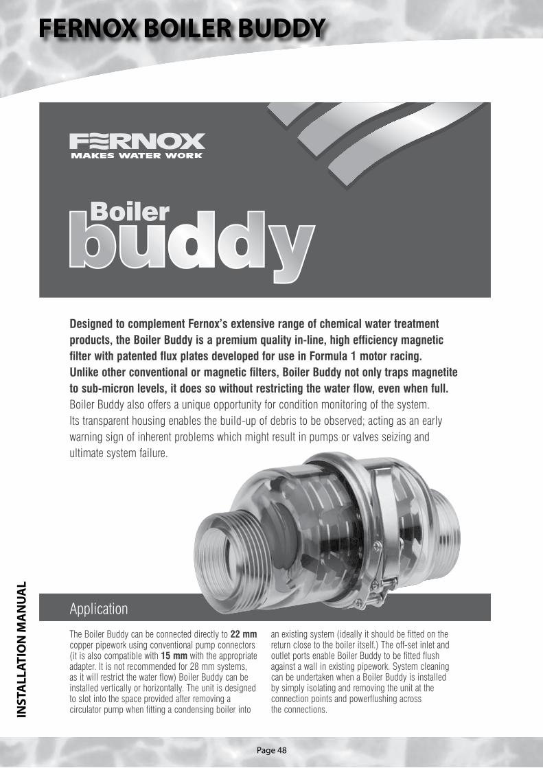
Page 48
FERNOX BOILER BUDDYIN
STA
LLA
TIO
N M
AN
UA
L
Designed to complement Fernox’s extensive range of chemical water treatmentproducts, the Boiler Buddy is a premium quality in-line, high efficiency magneticfilter with patented flux plates developed for use in Formula 1 motor racing. Unlike other conventional or magnetic filters, Boiler Buddy not only traps magnetiteto sub-micron levels, it does so without restricting the water flow, even when full. Boiler Buddy also offers a unique opportunity for condition monitoring of the system. Its transparent housing enables the build-up of debris to be observed; acting as an earlywarning sign of inherent problems which might result in pumps or valves seizing andultimate system failure.
The Boiler Buddy can be connected directly to 22 mmcopper pipework using conventional pump connectors(it is also compatible with 15 mm with the appropriateadapter. It is not recommended for 28 mm systems, as it will restrict the water flow) Boiler Buddy can beinstalled vertically or horizontally. The unit is designedto slot into the space provided after removing acirculator pump when fitting a condensing boiler into
Application
an existing system (ideally it should be fitted on thereturn close to the boiler itself.) The off-set inlet andoutlet ports enable Boiler Buddy to be fitted flushagainst a wall in existing pipework. System cleaningcan be undertaken when a Boiler Buddy is installed by simply isolating and removing the unit at theconnection points and powerflushing across the connections.

Page 49
FERNOX BOILER BUDDY
INST
ALL
ATI
ON
MA
NU
AL
How to install a Boiler Buddy
■ The Boiler Buddy has no moving parts and needs noadjustment once in service.
■ The body casing is transparent so that build-up ofcontamination can be observed.
■ It is normal for the magnet nearest the inlet of the Boiler Buddy to become full first. Once this is full thenext magnet will clog up followed by the next and soon. The Boiler Buddy has six magnets, we recommendcleaning the core when three magnets become full.
Points to consider
After installation
is removed from joints and does not enter the waterpipework. If soldered joints are being used to constructthe pipework, ensure solder or flux is wiped away toavoid corroding plastic parts. Do NOT undertake anysoldering while the Boiler Buddy is in the pipework.Boiler Buddy MUST be removed before soldering any joints.
■ Once installed, secure the tamper-proof tag to avoidaccidental opening. The tag must be replaced aftercleaning the core.
■ Complete the Boiler Buddy installation sticker and applyto the boiler.
■ Run the system and check for leaks.
■ It is recommended the Boiler Buddy is inspected andcleaned annually.
■ Boiler Buddy is designed to last the life of the centralheating system. More frequent cleaning of the core is anindication that the system has not been treated correctlywith Fernox Protectors, Restorers and cleansers.
Boiler Buddy has a transparent body casing so that the build-up of contamination on the core can be observed inservice. It has been designed to be fitted where it can be inspected and removed for cleaning and should be installedin the central heating return line as close to the boiler as possible.There are a variety of installations but in general the open-vented system and the sealed system are typical.
Vent pipe
Feed and expansion pipe
Boiler Buddy
Reliefvalve
Water main
Fillingstop cock
Filling loop
Return to boiler
Heatedwater feed to radiators
Heatedwater feed to radiators
Feed and expansion tank Expansion vessel
Boiler Buddy Return to boiler
Feed and expansion pipe
■ When selecting a position to install a Boiler Buddybeware of electrical connections in the vicinity, as thesewill be hazardous if they come into contact with water.
■ Install the Boiler Buddy with both an upstream anddownstream servicing valve.
■ Boiler Buddy is designed for use with standard 11/2" BSPx 22 mm pump servicing valves (on a 15 mm system werecommend fitting 22 to 15 mm reducing sets instead ofthree 22 mm olive in the pump servicing valves).
■ Boiler Buddy has a face-to-face dimension of 130 mm.■ If standard pump servicing valves are used, a total
space of 250 mm is required for installation.■ During installation ensure that all copper or plastic swarf

Page 50
FERNOX BOILER BUDDYIN
STA
LLA
TIO
N M
AN
UA
L
How to service and clean a Boiler Buddy
Once the Boiler Buddy has been safely removed from the system it can be disassembled. Fernox recommends that waterproof gloves are worn when cleaning the Boiler Buddy.
3 Cut off the tamper-proof tag4 Open the latch on the body clamp and slide off the
complete clamp over one end of the body
5 Pull the two halves apart
6 Remove the ‘o’ ring
Before removing the Boiler Buddy, place acontainer underneath the pipework to retain any water that may drip.
1 Isolate the Boiler Buddy from the system, by simplyclosing the quarter turn valves on the pump service connector
2 Once the Boiler Buddy has been isolated it can beremoved. Undo the two 11/2" BSP union nuts. Oncethese have been fully unscrewed the Boiler Buddy can be pulled out between the two flat faces. The twofibre washers may stick to the flat surface and tear onremoval of the Boiler Buddy, this is normal
WARNING: Under no circumstances attempt toremove the Boiler Buddy from the system byremoving the body clamp.

Page 51
FERNOX BOILER BUDDY
INST
ALL
ATI
ON
MA
NU
AL
Fernox, Cookson ElectronicsForsyth Road, Sheerwater, Woking, Surrey, GU21 5RZTel: 01483 793200 Fax: 01483 793201 Technical: 0870 870 0362
Email: [email protected] www.fernox.com
Spare partsThe Boiler Buddy is designed to last the life of theheating system. The following spare parts are availablefrom Fernox:✓ ‘O’ ring ✓ Tamper-proof tag✓ Spare clamp ✓ Spare core
12 Place the other body half over the ‘o’ ring; there arelocator pins to help the correct alignment of the two parts
13 Once the body is assembled, place the body clampover the flange and push the lever on the latch to the secured position
14 Pass the replacement tamper-proof tag through theslot in the latch ensuring that it also passes throughthe bridge on the latch. This will guard againstaccidental opening of the clamp
15 Using two new fibre washers place the Boiler Buddyback into the pipework between the two (pump)servicing valves
16 Tighten the union nuts until finger tight, after whichuse a spanner to tighten 1.8th of a turn or untilsecure. CAUTION: The body casing is a plastic partand will fail if excessive force is used
17 The servicing valves can be opened and flow of waterwill be observed through the Boiler Buddy
18 Run the heating system and check for leaks
7 Remove the complete core
8 To clean the core either use a stiff brush or holdunder running water perpendicular to the core (ensure that any magnetite is disposed of safely)
9 Wipe clean the inside surface of each half of the body casing
Once the core has been cleaned the BoilerBuddy can be reassembled.
10 Place the clean core into the cleaned body casing
11 Place the new ‘o’ ring into position in the groove
Desi
gned
by
Solid
Col
our 2
7 09
05
(ver
sion
2)

Page 52
FERNOX ALPHI-11P
RO
DU
CT
DA
TA

Page 53
FERNOX ALPHI-11
PR
OD
UC
T D
ATA

Page 54
TER
MS
AN
D C
ON
DIT
ION
S
1. We only do business upon the Conditions which appear below and no other. Unless we so agree in writing these Conditions shall apply in full to any supply of goods by us to the exclusion of any Conditions or terms sought to be imposed by any purchaser. These Conditions of Sale and Warranty Terms override those which are contained on the Invoice Forms and all Sales are now subject to these Conditions of Sale and Warranty terms only.2. PRICEOnce an order or call off has been accepted the price will be held for three months but if delivery is extended beyond that period at the customer’s request, then we reserve the right to amend the price when necessary. The company reviews its pricing annually to adjust for changes in our cost base. We reserve the right to alter prices at any time for severe movements in raw materials (mainly copper and steel). If there is to be a change we will give customers at least four weeks notice but anything delivered after that date will be at the revised price. An order may not be cancelled or varied after acceptance without the written consent of the company. Such cancellation or variation shall be subject to such reasonable charges as may be appropriate.3. SPECIFICATIONThe goods are supplied in accordance with the Specifications (if any) submitted to the Purchaser and any addi-tions and alterations shall be the subject of an extra charge. Any goods not so specified shall be in accordance with our printed literature or the literature of any of our component suppliers (subject to any modifications made since publication). If we adopt any changes in construction or design of the goods, or in the specification printed in our literature, the Purchaser shall accept the goods so changed in fulfilment of the order.4. PAYMENTThe invoice price of goods shall be payable within 30 days of despatch by us of our invoice for the goods or such longer time as may be stated by our quotation or invoice. If we receive payment in full on or before the due date we will allow an appropriate settlement discount except where we have quoted a special net price. If payment is not received in full on or before the due date we shall be entitled in addition to the invoice price to:(i) payment of a sum equal to any increase in the copper price supplement applicable to the particular goods sold between the date of receipt of order and the date of receipt of payment in full; and (ii) interest on any part of the invoice price unpaid after the due date at the rate of 3% per annum over the base rate for the time being of HSBC Bank plc.5. TIMEWe give estimates of delivery dates in good faith and time of delivery is not nor shall be made of the essence of any contract nor shall we be liable for any loss or damage occasioned by delay in delivery.6. DELIVERYWe deliver free normally by our own vehicles within 25 miles of any of our manufacturing depots. Delivery to any place more than 25 miles from one of our manufacturing depots may be subject to our quoted delivery charges. We reserve the right to make delivery of goods contained in one order by more than one consignment and at different times. Where a period is agreed for delivery and such period is not extended by our Agree-ment, the Purchaser shall take delivery within that period. If the Purchaser fails to take delivery, we shall be entitled at the Purchaser's risk and expense to store the goods at the Purchaser's premises or elsewhere and to demand payment as if they had been despatched. Off loading at point of delivery shall be the responsibility of and be undertaken by the Purchaser.7. SHORTAGES OR DAMAGEGoods must be inspected before signature of delivery note and any damage, shortage or discrepancy noted on the delivery note and the goods returned on the same vehicle. The buyer must also give us immediate written notice of the damage, shortage or discrepancy so that we may prompt investigation.8. RETURN OF GOODSGoods may not be returned to the Company except by prior written permission of an authorised officer of the Company and such return shall be subject to payment by the Purchaser of handling and re-stocking charges, transport and all other costs incurred by the Company.9. COMPANY LIABILITYAll our goods are made of the best materials from reputable manufacturers and where stated are manufac-tured to the appropriate British or European Standard. Complaints must be given to us immediately, before any action is taken, as responsibility cannot be accepted if repairs or renewals are attempted on site without our written authority.
Defects caused by corrosion or scale deposits are not covered by this guarantee save as expressly provided in paragraph (f) of this Condition 9.
Where we agree to rectify any defect, we reserve the right to undertake the work on our own premises. The following guarantee covers faulty materials and manufacture for the stated period, provided that:-• The unit has been installed in accordance with our installation and service instructions and all relevant codes
of practice and regulations in force at the time of installation.• That all necessary inlet controls and safety valves have been fitted correctly.• It has only been used for the storage of potable water supplied from the public mains.• Where appropriate the unit has been regularly maintained as detailed in the installation and service
instructions.(a) Domestic and Commercial Open Vented Cylinders and Tanks.The copper storage vessel is guaranteed for ten years and if it proves to be defective either in materials or workmanship, we will either repair or supply replacement at our option with the closest substitute in the case of any obsolete product to any address in Great Britain.(i) free of all charge during the first year after delivery by us.(ii) thereafter at a charge of one-tenth of the then current list price and any copper price supplement and delivery charge during the second year after delivery by us and increasing by a further one-tenth on the second and subsequent anniversary of delivery by us.(b) Domestic Mains Fed Products [Primary Stores]The copper storage vessel is guaranteed for five years and if it or any integral pipework as part of the storage vessel assembly proves to be defective either in materials or workmanship, we reserve the right to either repair or supply replacements or the closest possible substitute in the case of any obsolete product and will collect and deliver to any address in England, Wales and Scotland (excluding all Scottish Islands).(i) free of all charge during the first year after delivery by us.(ii) thereafter at a charge of one-fifth of the then current list price or any copper price supplement and deliv-ery charge during the second year after delivery by us increasing by a further one-fifth on the second and subsequent anniversary of delivery by us.
Gledhill (Water Storage) Ltd
(c) Integrated Boiler and Storage Vessel Products and Stand Alone BoilersIn the case of the GulfStream range of products and the Gledhill boiler range of products, Gledhill guarantees the heat exchanger (boiler) for material and construction faults for two years and FURTHER we will meet the installer/contractors reasonable costs in removing and replacing any DEFECTIVE heat exchanger up to a MAXIMUM of one third of the extent of our liability in regard to the replacement product.THE RESPONSIBILITY FOR THE EXECUTION OF THISGUARANTEE LIES WITH THE INSTALLER.The guarantee becomes null and void if the appliance is used incorrectly, or in the event of proven negligence or incor-rectly implemented repairs OR FAILURE TO CARRY OUT THE RECOMMENDED INSPECTION/MAINTENANCE. The guarantee also becomes null and void if changes are made to the appliance without our knowledge, or if the serial number on the appliance is removed or made illegible.The annual service must be carried out by a competent installer in accordance with the advice given by Gledhill and using Gledhill approved parts.(d) Stainless Steel Unvented CylindersGledhill guarantee the components including controls, valves and electrical parts for two years from the date of purchase. IT SHOULD BE NOTED THAT THE FACTORY FITTED TEMPERATURE AND PRESSURE RELIEF VALVE MUST NOT BE REMOVED OR ALTERED IN ANY WAY OR THE GUARANTEE WILL NOT BE VALID. GLEDHILL WILL NOT BE RESPONSIBLE FOR ANY CONSEQUEN-TIAL LOSS OR DAMAGE HOWEVER IT IS CAUSED. The guarantee for the stainless steel vessel is for twenty five years if the original unit is returned to us AND PROVIDED THAT:(i) It has been installed as per the Design, Installation & Servicing Instructions, relevant standards, regulations and codes of practice.(ii) It has not been modified, other than by Gledhill.(iii) It has not been subjected to wrong or improper use or left uncared for.(iv) It has only been used for the storage of potable water.(v) It has not been subjected to frost damage.(vi) The benchmark log book is completed after each annual service.(vii) The unit has been serviced annually.It should be noted that the guarantee does not cover:- the effects of scale build up- any labour charges associated with replacing the unit or parts.If the stainless steel vessel proves to be defective either in materials or workmanship we reserve the right to either repair or supply replacements or the closest possible substitute in the case of any obsolete product and will collect and deliver to any address in England, Scotland and Wales (excluding all islands):(i) free of charge during the first year after delivery by us.(ii)thereafter at a charge of one twenty fifth of the then cur-rent list price during the second year after delivery by us and increasing by a further one twenty fifth on the second and subsequent anniversary of delivery by us.ACTION IN THE EVENT OF FAILUREIf the Stainless Lite develops a leak we will ask for a deposit against the supply of a new one. This will be refunded if the failure is within the terms of the warranty when it has been examined by us.(e) Solar Panels and ancillary equipmentGledhill provides a five year warranty for defects in the col-lectors (except broken glass and collector accessories eg metal edgings). If the collector demonstrably fails to meet one of the requirements of the standard DIN 4757 part 3 we will replace it free of charge based on the date of invoice. We can not be responsible for damage caused by mechanical stress and/or changes caused by weather related influences. The warranty excludes minor surface damage that does not affect performance or malfunction due to improper assembly or installation.Please note:- Installation must have been carried out by a licensed special-
ized company (heating contractor or plumber) following the version of installation instructions in force.
- Gledhill or its representative was given the opportunity to check complaints on site immediately after any defect occurred.
- Confirmation exists that the system was commissioned properly and that the system was checked and maintenance was performed annually by a specialised company licensed for this purpose.
AMD. MAY 2007CONDITIONS OF SALE & WARRANTY TERMS

Page 55
TER
MS
AN
D C
ON
DIT
ION
S
(f ) Components of our products other than Storage Vessels and Integral Pipework. We will either extend to the purchaser the same terms of warranty as we are given by the manufacturer of the component or if the manufacturer does not give any warranty, replace free of charge any component which becomes defective within two years after the date of the delivery by us and is returned to us at the purchaser’s expense but we shall not meet the cost of removal or shipping or return of the component or any other cost charges or damages incurred by the purchaser.If the appliance manufactured by Gledhill incorporates a factory fitted scale inhibitor then during the period of three years from the date of delivery Gledhill will replace, free of charge, any plate heat exchanger fitted in the appliance as original equipment in which scale formation occurs that materially reduces the effectiveness of the plate heat exchanger. This guarantee does not extend to any other component installed within the Gledhill appliance or elsewhere in the Purchasers domestic water system.(g) GeneralIn the case of goods manufactured solely in accordance with our specification and designs and in respect of any installation work carried out by or on our behalf, our entire liability and the purchaser's sole remedies (subject to (a) - (f ) above) and shall be as follows:(a) we accept liability for death or personal injury to the extent that it results from our negligence that of our employees agents or subcontractors.(b) subject to paragraph (d) below, we accept liability for direct physical damage to tangible property to the extent that such damage is caused by our negligence that of our employees agents or subcontractors.(c) our total liability to the purchaser over and above any liability to replace under (1 - 4) above (whether in contract or in tort including negligence) in respect of any one cause of loss or damage claimed to result from any breach of our obligations hereunder, shall be limited to actual money damages which shall not exceed £20,000 provided that such monetary limit shall not apply to any liability on the part of ourselves referred to in paragraph (a) above.(d) except as provided in paragraph (a) above but otherwise notwithstanding any provision herein contained in no event shall we be liable for the following loss or damage howsoever caused and even if foreseeable by us or in our contemplation :-(i) economic loss which shall include loss of profits, business revenue, goodwill or anticipated savings.(ii) damages in respect of special indirect or consequential loss or damage (other than death, personal injury and damage to tangible property).(iii) any claim made against the purchaser by any other party(save as expressly provided in paragraph (b) above).(e) except in respect of our liability referred to in paragraph (a) above no claim may be made or action brought (whether in contract or in tort including negligence) by the purchaser in respect of any goods supplied by us more than one year after the date of the invoice for the relevant goods.(f ) nothing in these Conditions shall confer on the purchaser any rights or remedies to which the purchaser would not otherwise be legally entitled.10. LOSS OR INJURYNotwithstanding any other provision contained herein the Purchaser's hereby agree to fully indemnify us against any damages losses costs claims or expenses incurred by us in respect of any claim brought against us by any third party for :-(a) any loss injury or damage wholly or partly caused by any goods supplied by us or their use.(b) any loss injury or damage wholly or partly caused by the defective installation or sub-standard workman-ship or materials used in the installation of any goods supplied by us.(c) any loss injury or damage in any way connected with the performance of this contract.PROVIDED that this paragraph (6) will not require the Purchaser to indemnify us against any liability for our own acts of negligence or those of our employees agents or sub-contractors.FURTHER in the case of goods supplied by us which are re-sold to and installed by a third party by the Pur-chaser it will be the sole responsibility of the Purchaser to test the goods immediately after their installation to ensure that inter alia they are correctly installed and are in proper working order, and are not likely to cause any loss injury or damage to any person or property.11. VARIATION OF WARRANTY AND EXCLUSIONShould our warranty and exclusion be unacceptable we are prepared to negotiate for variation in their terms but only on the basis of an increase in the price to allow for any additional liability or risk which may result from the variation.Purchasers are advised to insure against any risk or liability which they may incur and which is not covered by our warranty.12. RISK AND RETENTION OF TITLE(a) goods supplied by us shall be at the Purchaser's risk immediately upon delivery to the Purchaser or into custody on the Purchaser's behalf or to the Purchaser's Order. The Purchaser shall effect adequate insurance of the goods against all risks to the full invoice value of the goods, such insurance to be effective from the time of delivery until property in the goods shall pass to the Purchaser as hereinafter provided.(b) property in the goods supplied hereunder will pass to the Purchaser when full payment has been made by the Purchaser to us for :-(i) the goods of the subject of this contract.(ii) all other goods the subject to of any other contract between the Purchaser and us which, at the time of payment of the full price of the goods sold under this contract, have been delivered to the Purchaser but not paid for in full.(c) until property in the goods supplied hereunder passes to the Purchaser in accordance with paragraph (2) above.(i) the Purchaser shall hold the goods in a fiduciary capacity for us and shall store the same separately from any other goods in the Purchaser's possession and in a manner which enables them to be identified as our goods.(ii) the Purchaser shall immediately return the goods to us should our authorised representative so request. All the necessary incidents associated with a fiduciary relationship shall apply.(d) the Purchaser's right to possess the goods shall cease forthwith upon the happening of any of the following events, namely :-(i) if the Purchaser fails to make payment in full for the goods within the time stipulated in clause 4 hereof.(ii) if the Purchaser, not being a company, commits any act of bankruptcy, makes a proposal to his or her creditors for a compromise or does anything which would entitle a petition for a Bankruptcy Order to be presented.(iii) if the Purchaser, being a company, does anything or fails to do anything which would entitle an administrator or an administrative receiver or a receiver to take possession of any assets or which would entitle any person to present a petition for winding up or to apply for an administration order.
(e) the Purchaser hereby grants to us an irrevocable licence to enter at any time any vehicle or premises owned or occupied by the Purchaser or in the possession of the Purchaser for the purposes of repossessing and recovering any such goods the property in which has remained in us under paragraph (2) above. We shall not be responsible for and the Purchaser will indemnify us against liability in respect of damage caused to any vehicle or premises in such repossession and removal being damaged which it was not reasonably practicable to avoid.(f ) notwithstanding paragraph (3) hereof and subject to paragraph (7) hereof, the Purchaser shall be permitted to sell the goods to third parties in the normal course of business. In this respect the Purchaser shall act in the capacity of our commission agent and the proceeds of such sale :-(i) shall be held in trust for us in a manner which enables such proceeds to be identified as such, and :(ii) shall not be mixed with other monies nor paid into an overdrawn bank account.We, as principal, shall remunerate the Purchaser as commis-sion agent a commission depending upon the surplus which the Purchaser can obtain over and above the sum, stipulated in this contract of supply which will satisfy us.(g) in the event that the Purchaser shall sell any of the goods pursuant to clause (6) hereof, the Purchaser shall forthwith inform us in writing of such sale and of the identity and address of the third party to whom the goods have been sold.(h) if, before property in the goods passes to the Purchaser under paragraph (2) above the goods are or become affixed to any land or building owned by the Purchaser it is hereby agreed and declared that such affixation shall not have the effect of passing property in the goods to the Purchaser. Furthermore if, before property in the goods shall pass to the Purchaser under paragraph (2) hereof, the goods are or become affixed to any land or building (whether or not owned by the Purchaser), the Purchaser shall:-(i) ensure that the goods are capable of being removed without material injury to such land or building.(ii) take all necessary steps to prevent title to the goods from passing to the landlord of such land or building.(iii) forthwith inform us in writing of such affixation and of the address of the land or building concerned.The Purchaser warrants to repair and make good any damage caused by the affixation of the goods to or their removal from any land or building and to indemnify us against all loss damage or liability we may incur or sustain as a result of affixation or removal.(i) in the event that, before property in the goods has passed to the Purchaser under paragraph (2) hereof, the goods or any of them are lost, stolen, damaged or destroyed :-(i) the Purchaser shall forthwith inform us in writing of the fact and circumstances of such loss, theft, damage or destruction.(ii) the Purchaser shall assign to us the benefit of any insur-ance claim in respect of the goods so lost, stolen, damaged or destroyed.13. NON-PAYMENTIf the Purchaser shall fail to make full payment for the goods supplied hereunder within the time stipulated in clause 4 hereof or be in default of payment for any other reason then, without prejudice to any of our other rights hereunder, we shall be entitled to stop all deliveries of goods and materials to the Purchaser, including deliveries or further deliveries of goods under this contract. In addition we shall be entitled to terminate all outstanding orders.14. RISKAll goods sold by us shall be at the sole risk of the Purchaserfrom the date of despatch by us of the invoice for their price.15. VALUE ADDED TAXAll prices quoted are exclusive of Value Added Tax which will be charged at the rate ruling at the date of despatch of invoice.16. TRADE SALES ONLYWe are only prepared to deal with those who are not consum-ers within the terms of the Unfair Contract Terms Act 1977, the Sale of Goods Act 1979 and the Supply of Goods and Services Act 1982. Accordingly any person who purchases from us shall be deemed to have represented that he is not a consumer by so purchasing.17. JURISDICTIONThe agreement is subject to English/Scottish law and any dispute arising hereunder shall be settled in accordance therewith dependent upon the location.

The code of practice for the installation,commissioning & servicing of central heating systems