A Comparison of Rocking Horse Loosening of Metal … Comparison of Rocking Horse Loosening of Metal...
1
A Comparison of Rocking Horse Loosening of Metal-Backed Versus All Polyethylene Glenoid Components 1 Kory Reed, 2 Michael Bisogno, 3 Kyle Sreniawski, 1 Paul Paterson, 2 Craig Howard, 2,3 Mark Ehrensberger 1 Excelsior Orthopedics, Buffalo, NY 2 Department of Orthopaedics, State University of New York at Buffalo, Buffalo, NY 3 Department of Biomedical Engineering, State University of New York University at Buffalo, Buffalo, NY Disclosures: Kory Reed (3B-Arthrex), Mike Bisogno (N), Kyle Sreniawski (N), Paul Patterson (1-Integra; 3B-Lima Corp, Coventus Ortho), Craig Howard (N), Mark Ehrensberger (5-Lima Corp, Zimmer-Biomet, Depuy-Synthes, Greatbatch, Hollister, Carestream, Enermed; 6-Symmetry), Introduction: Glenoid component loosening is a common mechanism of failure for total shoulder arthroplasty. The metal-backed glenoid of the Lima SMR Modular Shoulder Prosthesis has shown encouraging mid-term clinical outcomes 1 and the implant design and fixation strategy may offer a rationale for the improved performance of cementless MB glenoid components. The primary purpose of this study was to utilize a standardized laboratory test of rocking horse loading to evaluate the initial loosening of the SMR glenoid implant in three clinically relevant configurations. Methods: Thirty blocks of solid rigid polyurethane bone foam (20pcf foam, Sawbones, Vashon, WA) were machined to match the footprints of the glenoid implants and then potted within polymethymethacrylate (PMMA) cement such that 15mm of the bone foam protruded from the PMMA. The glenoid component of the SMR Modular Shoulder Prosthesis (Lima Corporate, Villanova di San Daniele, Italy) was tested in the following configurations (1) SMR cemented, all polyethylene, 3 peg glenoid (PE), (2) SMR cemented metal-backed glenoid (cemented MB), and (3) SMR screwed metal-back glenoid (screwed MB) with a 20mm superior screw and a 25mm inferior screw. All glenoid components were implanted according to the manufactures protocol and then mounted within a custom mechanical testing system that was based upon ASTM F 2028-08. As shown in Figure 1, the PMMA embedded bone foam (B) and glenoid component (A) construct was rigidly secured within a metal box (C). This metal box was secured to a rail system (D) that only allowed for horizontal (±) x-direction motion. The humeral head component (F) was mounted to a second rail system (G) that only allowed vertical (±) z-direction motion. This second rail was connected to the actuator (H) of a load frame system (Mini-Bionix II, MTS Corp, Eden Prairie, MN). A simulated joint reactive force of 750N was applied by a weight/pulley/cable system (E). The external housing of two spring-loaded linear variable differential transducers (LVDT- GCD-121-050, Schaevitz, Hampton, VA) were also fixed to the metal box (C) via a mounting plate (K). The tip displacements of the superior LVDT (I) and inferior LVDT (J) were coupled to the displacements of the superior and inferior edge of the glenoid component relative to the bone foam through a system of frictionless lever arms (L &M) and threaded pins (N &O) attached to the glenoid component. Rocking-horse displacement tests were performed by cyclically translating the humeral head to 90% of the superior and inferior subluxation distance (4.5mm), as described 2 , for 5000 cycles at 1 Hz. A custom data acquisition program synchronized collection of displacement data from the MTS actuator and the LVDTs such that the displacements of the inferior and superior glenoid component edges were tracked with respect to the humeral head off-center translation. A total of 10 cycles of data were collected after 10 cycles, after 100 cycles, then at intervals of every 100 cycles until 1,000 cycles, and finally at intervals of every 1,000 cycles until 5,000 cycles. The micromotion of the glenoid component edges was computed by subtracting the averaged position of the superior and inferior glenoid edges when the humeral head was at the neutral position from the averaged positions of the glenoid edges when the humeral head was at the maximum off-center locations, respectively. The micromotions at each implant edge were compared across the implant types at each cycle count with one-way ANOVAs followed by Tukey post-hoc analysis where appropriate. Student’s t-testd individually to compared each component’s inferior vs. superior compression and inferior vs. superior distraction. All statistical analysis was performed using SPSS statistical software (IBM, Armonk, NY) with a significance level defined as P<0.05. Results: Figure 2 shows the compressive micromotion on the superior (2A) and inferior (2B) implant edges and the distraction micromotion on the superior (2C) and the inferior (2D) implant edges for all three implant types. The cemented MB implant had the highest micromotion in all categories and will not be discussed further. The screwed MB component and PE component exhibited similar compression micromotion at both implant edges for all cycle counts. The screwed MB component and PE component exhibited similar distraction micromotion at the inferior edge for all cycle counts and at the superior edge until 2,000 cycles. At this point, the PE component had significantly less micromotion than the screwed component for the rest of the cycles. The PE and cemented MB components, both of which are symmetrical implants, showed no statistical differences when comparing their compression and distraction performance at the superior versus the inferior edges. The screwed MB component showed greater compression on the inferior edge than the superior edge starting at cycle 1,000 (Inferior =262±40µm, Superior =231±22µm, p=0.044) and continuing to cycle 5,000 (Inferior =298±43µm, Superior =245±33µm, p=0.006). The screwed MB component also showed smaller distraction at the inferior edge than the superior edge starting at cycle 10 (Inferior =79±21µm, Superior =102±19µm, p=0.019) and continuing throughout cycle 5,000 (Inferior =130±40µm, Superior =198±34µm, p=0.001). Discussion: The cemented MB exhibited the greatest micromotion throughout the rocking horse testing as compared to the other implant types. However, the screwed MB showed similar micromotion performance as compared to the PE glenoid during the first 1000 cycles. At 2000 cycles and beyond the only difference between the implant types was that the superior edge of the screwed MB showed significantly higher distraction as compared to the PE glenoid. Notably, the superior screw was 5mm shorter than the inferior screw. Therefore this study suggests that the longest screw possible, given patient anatomy, should be considered for fixation of screwed MB glenoids. A limitation of this time zero study is that it does not account for bony ingrowth which enhances MB implant stability. Clinically the goal is to limit micromotion to less than 150um during the 6-8 week post-op period to allow bony ingrowth. The screwed MB distraction was within this threshold during the first 1000 cycles, which corresponds to the relevant post-op period for bony ingrowth. 3 Significance: The screwed MB glenoid provides for initial implant stability that is comparable with the PE glenoid. The initial stability provided by this fixation strategy may, in part, be a contributing factor in the bony ingrowth and good mid-term clinical outcomes with this implant. References 1. Castagna A et al, JBJS Br 2010;92(10):1410-5. 2. Anglin C et al, JSES 2000;9(4):323-31. 3. Budge M et al, JSES 2013;22(5):709-15. Figure 2: Plots of compressive micromotion on the superior (2A) and inferior (2B) edges and the distraction micromotion on the superior (2C) and inferior (2D) edges for all implant types. The “a” denotes statistically unique group and the * denotes statistical differences between groups as noted. Figure 1: Photos of the rocking-horse test system ORS 2016 Annual Meeting Poster No. 2029
Transcript of A Comparison of Rocking Horse Loosening of Metal … Comparison of Rocking Horse Loosening of Metal...
A Comparison of Rocking Horse Loosening of Metal-Backed Versus All Polyethylene Glenoid Components 1Kory Reed, 2Michael Bisogno, 3Kyle Sreniawski, 1Paul Paterson, 2Craig Howard, 2,3Mark Ehrensberger
1 Excelsior Orthopedics, Buffalo, NY 2Department of Orthopaedics, State University of New York at Buffalo, Buffalo, NY
3Department of Biomedical Engineering, State University of New York University at Buffalo, Buffalo, NY Disclosures: Kory Reed (3B-Arthrex), Mike Bisogno (N), Kyle Sreniawski (N), Paul Patterson (1-Integra; 3B-Lima Corp, Coventus Ortho), Craig Howard (N), Mark Ehrensberger (5-Lima Corp, Zimmer-Biomet, Depuy-Synthes, Greatbatch, Hollister, Carestream, Enermed; 6-Symmetry), Introduction: Glenoid component loosening is a common mechanism of failure for total shoulder arthroplasty. The metal-backed glenoid of the Lima SMR Modular Shoulder Prosthesis has shown encouraging mid-term clinical outcomes1 and the implant design and fixation strategy may offer a rationale for the improved performance of cementless MB glenoid components. The primary purpose of this study was to utilize a standardized laboratory test of rocking horse loading to evaluate the initial loosening of the SMR glenoid implant in three clinically relevant configurations. Methods: Thirty blocks of solid rigid polyurethane bone foam (20pcf foam, Sawbones, Vashon, WA) were machined to match the footprints of the glenoid implants and then potted within polymethymethacrylate (PMMA) cement such that 15mm of the bone foam protruded from the PMMA. The glenoid component of the SMR Modular Shoulder Prosthesis (Lima Corporate, Villanova di San Daniele, Italy) was tested in the following configurations (1) SMR cemented, all polyethylene, 3 peg glenoid (PE), (2) SMR cemented metal-backed glenoid (cemented MB), and (3) SMR screwed metal-back glenoid (screwed MB) with a 20mm superior screw and a 25mm inferior screw. All glenoid components were implanted according to the manufactures protocol and then mounted within a custom mechanical testing system that was based upon ASTM F 2028-08. As shown in Figure 1, the PMMA embedded bone foam (B) and glenoid component (A) construct was rigidly secured within a metal box (C). This metal box was secured to a rail system (D) that only allowed for horizontal (±) x-direction motion. The humeral head component (F) was mounted to a second rail system (G) that only allowed vertical (±) z-direction motion. This second rail was connected to the actuator (H) of a load frame system (Mini-Bionix II, MTS Corp, Eden Prairie, MN). A simulated joint reactive force of 750N was applied by a weight/pulley/cable system (E). The external housing of two spring-loaded linear variable differential transducers (LVDT-GCD-121-050, Schaevitz, Hampton, VA) were also fixed to the metal box (C) via a mounting plate (K). The tip displacements of the superior LVDT (I) and inferior LVDT (J) were coupled to the displacements of the superior and inferior edge of the glenoid component relative to the bone foam through a system of frictionless lever arms (L &M) and threaded pins (N &O) attached to the glenoid component. Rocking-horse displacement tests were performed by cyclically translating the humeral head to 90% of the superior and inferior subluxation distance (4.5mm), as described2, for 5000 cycles at 1 Hz. A custom data acquisition program synchronized collection of displacement data from the MTS actuator and the LVDTs such that the displacements of the inferior and superior glenoid component edges were tracked with respect to the humeral head off-center translation. A total of 10 cycles of data were collected after 10 cycles, after 100 cycles, then at intervals of every 100 cycles until 1,000 cycles, and finally at intervals of every 1,000 cycles until 5,000 cycles. The micromotion of the glenoid component edges was computed by subtracting the averaged position of the superior and inferior glenoid edges when the humeral head was at the neutral position from the averaged positions of the glenoid edges when the humeral head was at the maximum off-center locations, respectively. The micromotions at each implant edge were compared across the implant types at each cycle count with one-way ANOVAs followed by Tukey post-hoc analysis where appropriate. Student’s t-testd individually to compared each component’s inferior vs. superior compression and inferior vs. superior distraction. All statistical analysis was performed using SPSS statistical software (IBM, Armonk, NY) with a significance level defined as P<0.05. Results: Figure 2 shows the compressive micromotion on the superior (2A) and inferior (2B) implant edges and the distraction micromotion on the superior (2C) and the inferior (2D) implant edges for all three implant types. The cemented MB implant had the highest micromotion in all categories and will not be discussed further. The screwed MB component and PE component exhibited similar compression micromotion at both implant edges for all cycle counts. The screwed MB component and PE component exhibited similar distraction micromotion at the inferior edge for all cycle counts and at the superior edge until 2,000 cycles. At this point, the PE component had significantly less micromotion than the screwed component for the rest of the cycles. The PE and cemented MB components, both of which are symmetrical implants, showed no statistical differences when comparing their compression and distraction performance at the superior versus the inferior edges. The screwed MB component showed greater compression on the inferior edge than the superior edge starting at cycle 1,000 (Inferior =262±40µm, Superior =231±22µm, p=0.044) and continuing to cycle 5,000 (Inferior =298±43µm, Superior =245±33µm, p=0.006). The screwed MB component also showed smaller distraction at the inferior edge than the superior edge starting at cycle 10 (Inferior =79±21µm, Superior =102±19µm, p=0.019) and continuing throughout cycle 5,000 (Inferior =130±40µm, Superior =198±34µm, p=0.001). Discussion: The cemented MB exhibited the greatest micromotion throughout the rocking horse testing as compared to the other implant types. However, the screwed MB showed similar micromotion performance as compared to the PE glenoid during the first 1000 cycles. At 2000 cycles and beyond the only difference between the implant types was that the superior edge of the screwed MB showed significantly higher distraction as compared to the PE glenoid. Notably, the superior screw was 5mm shorter than the inferior screw. Therefore this study suggests that the longest screw possible, given patient anatomy, should be considered for fixation of screwed MB glenoids. A limitation of this time zero study is that it does not account for bony ingrowth which enhances MB implant stability. Clinically the goal is to limit micromotion to less than 150um during the 6-8 week post-op period to allow bony ingrowth. The screwed MB distraction was within this threshold during the first 1000 cycles, which corresponds to the relevant post-op period for bony ingrowth.3 Significance: The screwed MB glenoid provides for initial implant stability that is comparable with the PE glenoid. The initial stability provided by this fixation strategy may, in part, be a contributing factor in the bony ingrowth and good mid-term clinical outcomes with this implant. References 1. Castagna A et al, JBJS Br 2010;92(10):1410-5. 2. Anglin C et al, JSES 2000;9(4):323-31. 3. Budge M et al, JSES 2013;22(5):709-15.
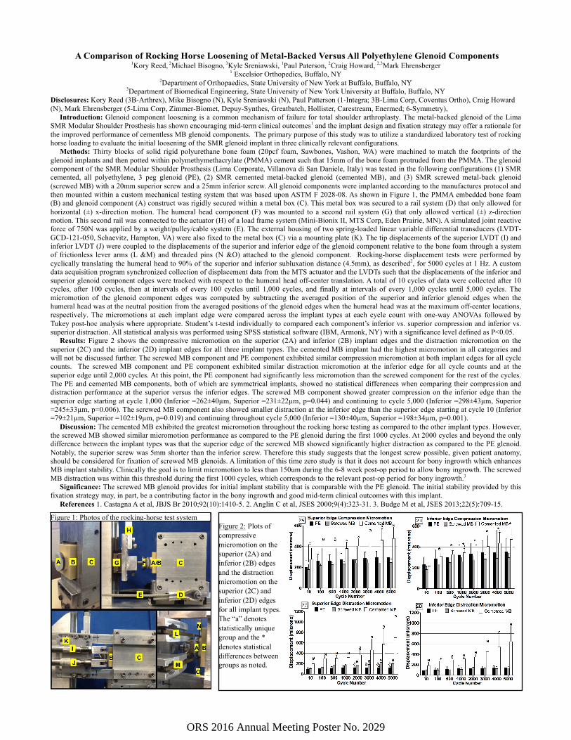
Figure 2: Plots of compressive micromotion on the superior (2A) and inferior (2B) edges and the distraction micromotion on the superior (2C) and inferior (2D) edges for all implant types. The “a” denotes statistically unique group and the * denotes statistical differences between groups as noted.
Figure 1: Photos of the rocking-horse test system
ORS 2016 Annual Meeting Poster No. 2029