A comparison of American and European ultrasonic testing ... · PDF...
78
NBSIR 79-1790 A Comparison of American and European Ultrasonic Testing Standards Sam Golan Office of Nondestructive Evaluation National Measurement Laboratory National Bureau of Standards Washington, DC 20234 L June 1 979 Issued August 1 979 -QO— - 100 . U56 70-1790 Prepared for: National Bureau of Standards Department of Commerce Washington, DC 20234
Transcript of A comparison of American and European ultrasonic testing ... · PDF...
NBSIR 79-1790
A Comparison of American andEuropean Ultrasonic TestingStandards
Sam Golan
Office of Nondestructive Evaluation
National Measurement Laboratory
National Bureau of Standards
Washington, DC 20234
L
June 1 979
Issued August 1 979
-QO—
-
100
. U56
70-1790
Prepared for:
National Bureau of StandardsDepartment of CommerceWashington, DC 20234


«&
r
NBSIR 79-1790aciU
v $oA COMPARISON OF AMERICAN ANDEUROPEAN ULTRASONIC TESTINGSTANDARDS
Sam Golan
Office of Nondestructive Evaluation
National Measurement Laboratory
National Bureau of Standards
Washington, DC 20234
June 1979
Issued August 1979
Prepared for:
National Bureau of Standards
Department of CommerceWashington, DC 20234
U.S. DEPARTMENT OF COMMERCE, Juanita M. Kreps, Secretary
Luther H. Hodges, Jr., Under Secretary
Jordan J. Baruch, Assistant Secretary for Science and Technology
NATIONAL BUREAU OF STANDARDS, Ernest Ambler. Acting Director


A Comparison of American and European UltrasonicTesting Standards
by
S. Golan*
ABSTRACT
In this report twenty-seven general ultrasonic testing standards
from eleven countries and international organizations are reviewed and
evaluated. Also, thirty-seven ultrasonic testing standards for specific
products, from five countries, are examined in order to evaluate their
utilization of the general ultrasonic testing standards, i.e., the
extent to which the procedures outlined In the general standards are
applied by the product standards. Finally, the "universal" concept of
ultrasonic testing standards versus the "specific", product-oriented
concept is discussed.
* Permanent address, Israel Institute of Metals, Israel. This reportwas prepared while the author was on a temporary assignment to theNBS Office of Nondestructive Evaluation.
3
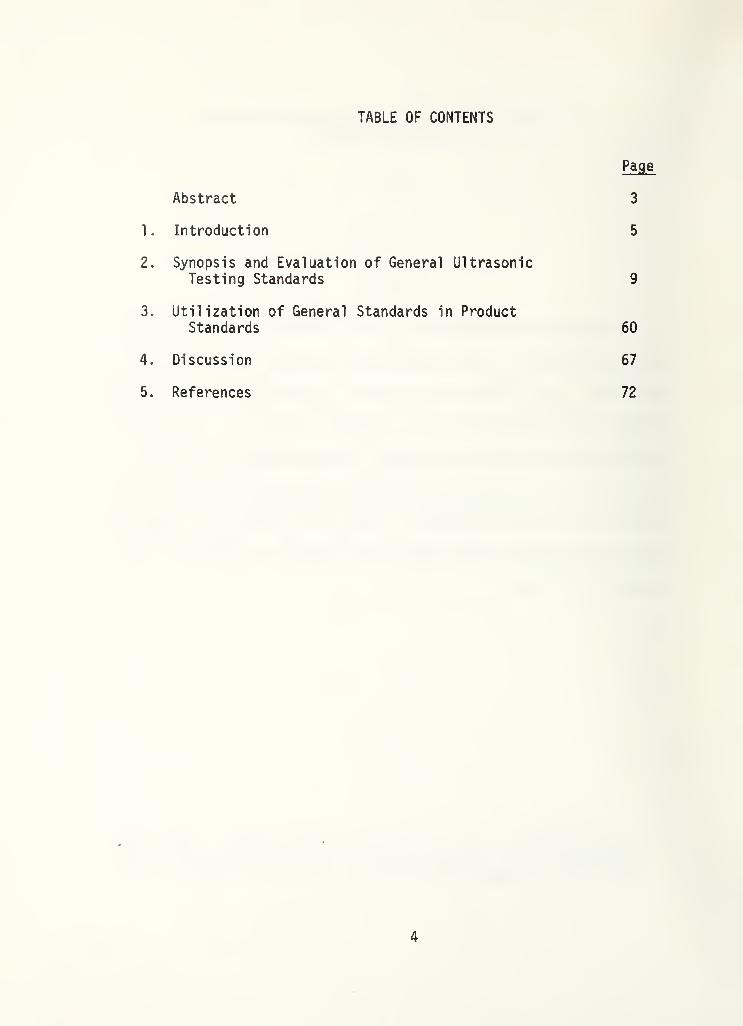
TABLE OF CONTENTS
Page
Abstract 3
1. Introduction 5
2. Synopsis and Evaluation of General UltrasonicTesting Standards 9
3. Utilization of General Standards in ProductStandards 60
4. Discussion 67
5. References 72
4
1. INTRODUCTION
Standards are used to assure uniform and reproducible measurements
and to achieve acceptable levels of quality of products. Measurement
techniques which are capable of expressing the required quality in
quantitative terms with reasonable precision and accuracy can help to
ascertain the true quality of a product. Unfortunately, NDE techniques
generally, and the ultrasonic technique particularly, are quite limited
in their ability to express quality in quantitative terms because our
knowledge of the interaction between the ultrasonic field and the tested
medium and of the relation between measured quality (changes in the
energy field) and required quality (integrity) is limited to idealized,
simplified models. These models usually do not adequately simulate real
situations, which are far more complex. Consequently, ultrasonic test
methods provide basically qualitative information. Ultrasonic testing
standards, based on empirical methods and practical considerations such
as cost, production and safety requirements, state of the art of instru-
mentation technology and personnel qualification, attempt to reach a
certain degree of quantification and comparability, without which the
use of the ultrasonic technique as a quality inspection tool would not
be possible.
The need for standardization was apparent in the early stages of
use of the ultrasonic technique. This led to local and national ini-
tiatives, the results of which were an output of various specifications
5

and standards. Various reference blocks with flat-bottom hole, side-
drilled hole, notch, groove, slit, ball and bottom reflectors for the
calibration of ultrasonic testing systems and for flaw characterization
have been specified by different standards in different countries. The
diversity does not necessarily reflect differences in product quality,
but is rather a result of different approaches taken by different
initiators.
Although lists of ultrasonic standards have been published [1-3]
this is believed to be the first attempt to synopsize and evaluate the
most important national and international ultrasonic testing standards.
In most countries a central standards institution is responsible
for the preparation and promulgation of national standards; for example,
consider the British Standards Institute in the United Kingdom, Associ-
ation Francaise de Normalization in France, Deutscher Normenausschuss in
West Germany, etc. In the United States, however, many organizations
prepare and promulgate standards. In a list of nondestructive testing
standards and specifications prepared by the American Society for
Nondestructive Testing (ASNT) technical council [3], more than ten U.S.
organizations that promulgate nondestructive testing standards are
listed. U.S. standards considered in this review are primarily American
Society for Testing and Materials (ASTM) standards which have gained
general recognition in the United States and are well known in other
countries.
6
Ultrasonic testing standards can be divided into two main groups;
standards for general application and standards for the testing of
specific products. This review is primarily concerned with the general
standards, but standards which apply to a wide group of products char-
acterized by their technology of production (welding, forging, casting,
etc.) are also included.
The general standards address three main subject areas:
1. Evaluation and characterization of ultrasonic testing
systems and system components.
2. Description of testing methods and testing procedures.
3. Reference blocks.
Usually a standard deals with more than one subject area. For
instance, British Standard BS 4331 describes both the evaluation of
systems and reference blocks. ASTM Standard E-164 is a recommended
practice for the testing of welds and includes a description of
reference blocks.
The standards are evaluated and discussed according to the
following criteria:
7

1. Whether the standard is simple to use.
2. The extent to which the standard is referenced in product
standards.
3. The amount and the quality of information that the standard
provides.
8

2. SYNOPSIS AND EVALUATION OF GENERAL ULTRASONIC TESTING STANDRDS
A list of organizations, theis given in Table 1. The generalare listed in Table 2.
standards of which are reviewed here,
ultrasonic testing standards themselves
Table 1. Standards Organizations
CountryStandards
Designation Organization
Austral ia AS Standards Association of Australia
Austria ON Osterreichi sches Normungsi nsti tut
France NF Association Francais de Normalization(AFNOR)
International IIW International Institute of Welding
International ISO International Organization forStandardization
Netherlands NEN Nederl ands Normal i sat i c- Inst i tunt
Sweden SIS Sveriges Standardizezingskommission
United Kingdom BS British Standards Institution
United States ANSI American National Standards Institute
ASME American Society of MechanicalEngineers
ASTM American Society for Testing andMaterials
AWS American Welding Society
Union of SovietSocialist Republics
GOST Gosudarstviennye Komitet StandartovSovieta Ministrov SSSR (USSR State
Committee for Standards)
West Germany DIN Deutscher Normenausschuss
9
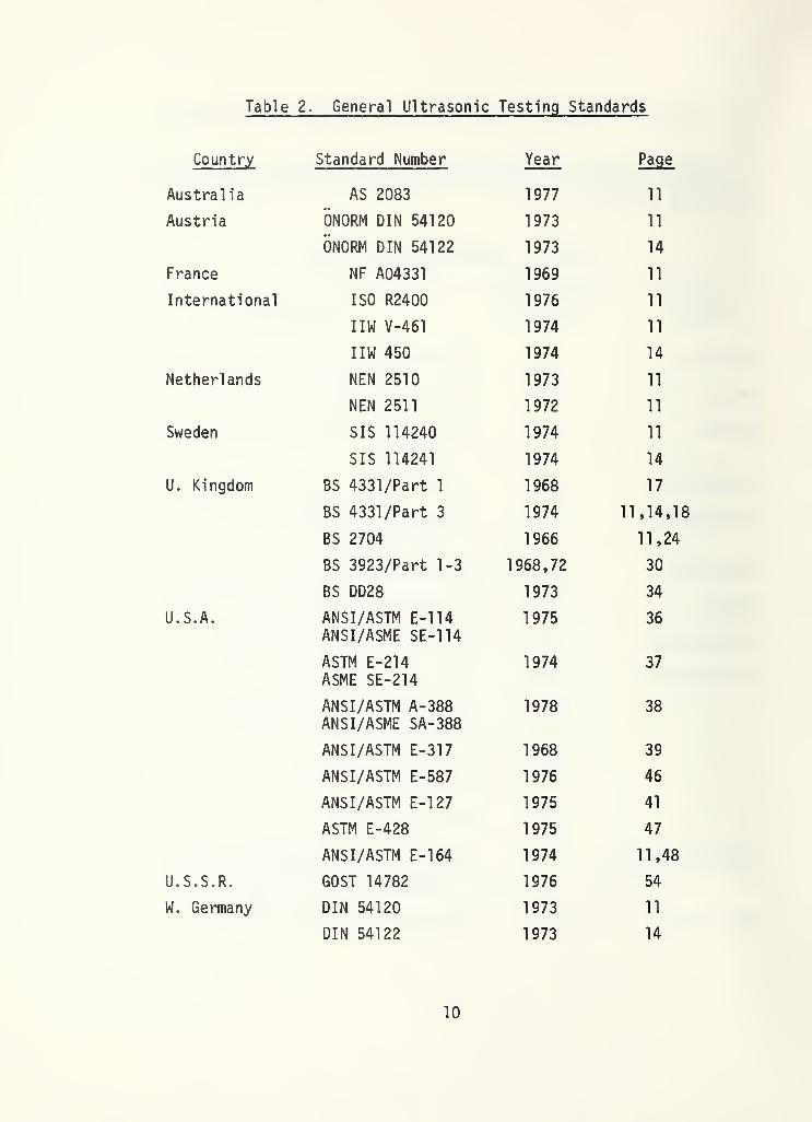
Table 2. General Ultrasonic Testing Standards
Country Standard Number Year Page
Austral ia AS 2083 1977 11
Austria 0N0RM DIN 54120 1973 11
ONORM DIN 54122 1973 14
France NF A04331 1969 11
International ISO R2400 1976 11
IIW V-461 1974 11
IIW 450 1974 14
Netherlands NEN 2510 1973 11
NEN 2511 1972 11
Sweden SIS 114240 1974 11
SIS 114241 1974 14
U. Kingdom BS 4331/Part 1 1968 17
BS 4331 /Part 3 1974 11,14,18
BS 2704 1966 11,24
BS 3923/Part 1-3 1968,72 30
BS DD28 1973 34
U.S.A. ANSI/ASTM E-114ANSI/ASME SE-114
1975 36
ASTM E-214ASME SE-214
1974 37
ANSI/ASTM A-388ANSI/ASME SA-388
1978 38
ANSI/ASTM E-317 1968 39
ANSI/ASTM E-587 1976 46
ANSI/ASTM E-127 1975 41
ASTM E-428 1975 47
ANSI/ASTM E-164 1974 00
U.S.S.R. GOST 14782 1976 54
W. Germany DIN 54120 1973 11
DIN 54122 1973 14
10

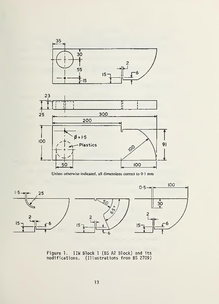
2.1 1 1 W Calibration Block 1 and Its Use forAdjustment and Control of Ultrasonic Testing Systems
Block 1 (Fig. 1) has been adopted in numerous standards, most of
which are listed below.
W. Germany DIN 54120 (1973)
Austria DIN 54120 (1973)
U. Kingdom BS 2704* (1966)
France NF A04331 (1964)
Netherlands NEN 2510 (1973)
Austral ia AS 2085 (1977)
Sweden SIS 114240 (1974)
U.S.A. ASTM E-164 (1974)
International ISO 2400 (1972)
International IIW V-461 (1971)
2.1.1 Synopsis
The standards describe a calibration block and its use for system
adjustment to test carbon and low alloy steel using normal and angle-
beam contact techniques.
* In BS 2704 IIW Block 1 is referred to as A. 2.
11

The following operations may be performed using the block and its
modifications:
1. Check of time base linearity.
2. Setting of range and zero point.
3. Determination of exit point of central beam of transducer.
4. Determination of angle of refraction.
5. Setting of working sensitivity.
6. Estimation of resolution.
2.1.2 Evaluation
The design of Block 1 permits the tester to perform the most common
system adjustments. If additional parameters, such as beam profile and
dead zone, are required, complementary blocks are necessary (see pages
18-23). Practical considerations are that the block has a rather com-
plicated design and is somewhat heavy to handle, especially when
slippery from couplant oil. IIW Block 2 (see pages 14-16) has been
designed to overcome this deficiency. Block 1 is the most popular block
in Europe, it is used by the welding industry in the U.S., and it is
recognized by the international organizations, ISO and IIW. Its main
advantages are that many important parameters which determine the
quality of a test can be monitored with this single block and that it is
applicable to both normal and angle-beam techniques.
12
35
Unless otherwise indicated, all dimensions correct to 01 mm
Figure 1. I I W Block 1 (BS A2 Block) and its
modifications. (Illustrations from BS 2709)
13

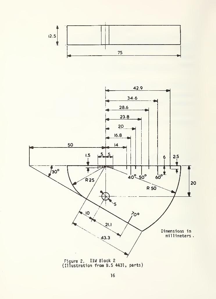
2.2 IIW Calibration Block 2 and Its Use for theAdjustment and Control of Ultrasonic Systems
Block 2 was adopted for use in the following standards:
W. Germany
Austria
Netherlands
Sweden
International
U. Kingdom
DIN 54122 (1973)
DIN 54122 (1973)
NEN 2411 (1972)
SIS 114241 (1974)
IIW 450 (1974)
BS 4331/3 (1974)
2.2.1 Synopsis
The standards describe a calibration block (Fig. 2) and its use for
system adjustment to test carbon and low alloy steel by normal and
angle-beam contact techniques. The following operations may be per-
formed using this block:
1. Check of time base linearity.
2. Setting of range and zero point.
3. Determination of exit point of central beam of transducer.
4. Determination of angle of refraction.
5. Setting of working sensitivity.
14

2.2.2 Evaluation
1 1 W Block 2 is suitable for the most common types of system.
*
adjustment. The most important parameters of a system which determine
the quality of a test can be monitored with this single block. It is
applicable to both normal and angle-beam techniques.
It does not offer as much in scope as Block 1, but it has the
advantage of being much smaller and lighter (0.2 kg compared to 4.5 kg
for Block 1). Because it is easy to handle, it is very practical to use
in field tests. Thus, the test setup can be frequently checked and any
necessary resetting accomplished.
15
4
5
t
75
16

2.3 Methods for Assessing the Performance of Ultrasonic FlawDetection Equipment, Part 1 - Overall Performance,
BS 4331 (19681
2.3.1 Synopsis
This standard provides a method for evaluating the most basic
performance requirements of ultrasonic testing systems. Using IIW
Block 1, the following system characteristics are determined:
1. Linearity of time base.
2. Linearity of amplification.
3. Resolution.
4. Maximum penetrating power.
2.3.2 Evaluation
The standard provides a simple method for evaluating four basic
performance characteristics. This, together with BS 4331 Part 2 for
electrical performance, is apparently the only standard in Europe for
evaluating an ultrasonic testing system independently of specific test
conditions. It is, however, limited in the sense that only the results
from similar types of apparatus using similar transducers and identical
coupling conditions can be compared.
17

2.4 Methods for Assessing Performance Characteristics ofUltrasonic Flaw Detection Equipment,
Part 3 - Guidance On The In-Service Monitoring ofProbes (excluding immersion probes), BS 4331 (1974)
2.4.1 Synopsis
This standard comprehensively covers the characteristics of normal
and angle-beam contact transducers. Methods and blocks for evaluating
the following parameters are specified:
1. Point of exit of central beam.
2. Beam angle.
3. Beam profile.
4. Dominant frequency.
5. Pulse length.
6. Dead zone.
7. Length of near field.
8. Signal-to-noise ratio.
9. Overall system gain (periodic check of stability).
10. Beam alignment.
18

11 . Depth resolution.
12. Angular resolution.
Some of these parameters are determined with the conventional European
blocks, IIW Block 1 (Fig. 1) or IIW Block 2 (Fig. 2). Other parameters
are determined with specially designed blocks, some of which are shown
in Figures 3-5.
2.4.2 Evaluation
BS 4331 Part 3 is the most comprehensive standard for evaluating
the characteristics of contact transducers in in-service conditions. It
covers many parameters of the transducer which most strongly affect the
quality of flaw detection. The evaluations of beam profile, beam align-
ment, depth resolution, angular resolution and near field, which are
often overlooked in other standards, are specified here.
Unlike Parts 1 and 2 of this standard, which describe a general
evaluation method for the overall performance and the electrical per-
formance of equipment, this part is intended to standardize checking
procedures which should be performed under conditions simulating the
specific work to be performed. It is not a general characterization of
the transducer itself, but a characterization of its performance under
real and specific conditions.
19
The presentation of the standard is very clear and accurate and
includes many drawings to illustrate the text,
cedures are simple and can easily be performed
service conditions.
The evaluation pro-
by the tester under in-
20

w
profile. (Illustration from BS 4331 Part 3)
21

(a)
Resolution holes
spaced as shown—in view (c) below
(Dimensions in millimeters)
Figure 4. Monitoring of beam profile of angle-beam transducers:
(a) block, (b) beam profile. (Illustrations from BS 4331 Part 3)
22

Dimensions in millimeters.
Figure 5. Block used to check depth resolution, dead zonedominant frequency and pulse length. (Illustration fromBS 4331 Part 3)
23
2.5 Specification for Calibration Blocks and Recommendationsfor Their Use in Ultrasonic Flaw Detection, BS 2074 (1966)
2.5.1 Synopsis
This standard contains specifications for the design and appli-
cation of different ultrasonic calibration blocks. These blocks are
used to test carbon and low alloy steel with normal and angle-beam
contact transducers. The various blocks enable adjustment and
evaluation of the following parameters:
1. time base linearity
2. range and zero point
3. working sensitivity
4. beam characteristic
5. dead zone
6. resolution
Block BS A1 (Fig. 6) is used to set the sensitivity and to
characterize the beam of an angle-beam transducer. Block BS A2 is
identical to 1 1 W Block 1, which was described on pages 11-13 (Fig. 1).
Block BS A3, known as the Sulzer Block (Fig. 7) has the same application
as Block A2.
24

2 in
Tolerance on length and width ± 0-05 in (1-25 mm)Tolerance on thickness ± 0-005 in (0-125 mm)
Figure 6. B.S Block A1 (Illustration from B.S 2704)
25

360
T~15
85
i
l
i
~T30
1Unless otherwise indicated ail dimensions correct to 0-1 nun
Figure 7. B.S Block A3 (Illustration from B.S 2704)
26

The standard is extended by several appendices which contain the
following information.
App. A Determination of angle and index of angle beam transducers,
and the time base linearity for the contact angle beam
technique.
App. B Description of transducer radiation pattern.
App. C Definition and method of monitoring of the effective
beam form.
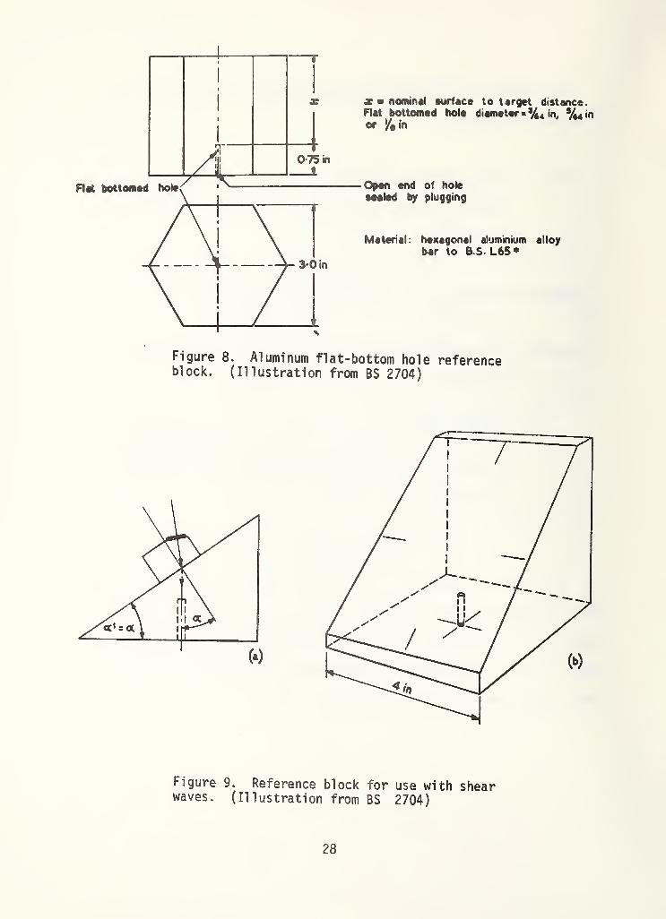
App. D Description of two types of flat-bottom hole reference
blocks; one each for use with compressional and shear
waves (see Figs. 8 and 9).
2.5.2 Evaluation
This standard together with BS 4331, previously described, are the
basic ultrasonic testing standards in the U.K. It contains a detailed
description of reference blocks A1 , A2 (IIW Block 1) and A3 (Figs. 1, 6
and 7) and their applications. The presentation is very clear and the
text contains many explanatory drawings.
27
jc * nominal surface to target distance.Rat bottomed hole diameter»%4 in, V44 in
or in
Open end of hole
sealed by plugging
Material: hexagonal aluminium alloy
bar to B.S. L65 *
Figure 8. Aluminum flat-bottom hole referenceblock. (Illustration from BS 2704)
Figure 9. Reference block for use with shearwaves. (Illustration from BS 2704)
28

This standard, BS 4331 Part 3 and ASTM E-127 are apparently the
only existing standards which contain information on ultrasonic trans-
ducer beam characterization. This is also the only standard which
describes flat-bottom hole wedge- type reference blocks for use with
shear waves. It seems, however, that the A.l block and the wedge-type
blocks have not gained wide recognition. The characteristics monitored
with the block can be determined with the more universal IIW Block 1.
Instead of using a series of wedge blocks with different angles, hole
diameters and hole depth for shear-beam characterization, it is more
convenient to use the block shown in Figure 4.
29

2.6 Methods for Ultrasonic Examinations of Welds, BS 3923
Part 1 . Manual Examination of Fusion Welded Butt Joints in
Ferritic Steels (1968);
Part 2 . Automatic Examination of Fusion Welded Butt Joints in
Ferritic Steels (1972);
Part 3 . Manual Examination of Nozzle Welds (1973).
2.6.1 Synopsis
The three parts of this standard provide methods for examining butt
welds in ferritic steels. The performance characteristics of the
ultrasonic system and the transducer specified in the standard are
calibrated and evaluated according to BS 2704 (see pages 24-29) and
according to procedures described in BS 4331, Part 3 (see pages
18-23). The scans are specified so as to insure examination of the
complete volume of the weld for both longitudinal and transverse!
defects. Guidance on transducer selection is given, and procedures are
suggested for determining the location and for estimating the size and
nature of flaws. The contact method is applied for manual examination
(Parts 1 and 3) and the gap or immersion method for automatic
examination (Part 3).
30

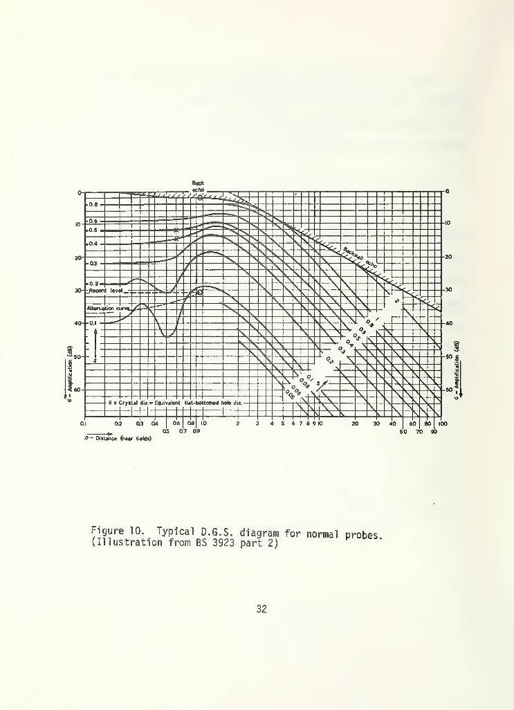
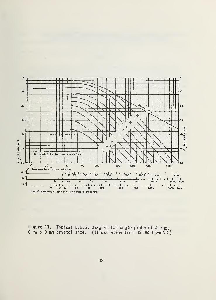
Parts 2 and 3 also contain a detailed description of procedures for
achieving a given sensitivity, for measuring attenuation coefficients
and for evaluation of flaw size using D6S (Distance-Gain-Sensitivity)
diagrams for normal and angle-beam transducers (see Figs. 10,11).
2.6.2 Evaluation
This is a very practical and detailed description of methods by
which a complete ultrasonic examination of butt welds can be performed.
The procedures are clearly and simply set forth. In addition, this is
one of the few standards which describe the use of the DGS diagrams for
flaw sizing. However, the accuracy, with which the flaws can be char-
acterized is largely dependent on the performance characteristics of the
system, the characteristics of the particular weld, and the skill and
experience of the tester. Consequently, the level of quantification is
quite limited.
31
-
Amplification
(dB)
Sack
Figure 10. Typical D.G.S. diagram for normal(Illustration from BS 3923 part 2)
probes.
32
Amplification
(dB)
0 10 20 SO 100 200 SOO 1000 2000 5000 7000
Flaw distance along surface from front edge of probe (mm)
Figure 11. Typical8 mm x 9 mm crystal
D.G.S. diagram for angle probe of 4 MHz,size. (Illustration from BS 3923 part 2)
33
~
Amplification
(dB)

2.7 Method for Ultrasonic Inpsection of Turbine and
Compressor Discs Using the (DGS) Diagram, DD28 (1973T
2.7.1 Synopsis
DD28, a Draft for Development, Is not yet a recognized standard.
It was reviewed in this study as an example of an advanced, quantitative
technique of the pulse-echo immersion method. With this technique the
size of the flaw is determined by applying the DGS diagram (Figs. 10,
11). Parameters such as attenuation, beam characteristic, near field,
dominant frequency, and effective transducer diameter, which can usually
be neglected when applying the conventional pulse-echo flaw-detection
technique, must be determined with great precision. A detailed pro-
cedure to determine these parameters and to calibrate the system is
outlined. The system consists of an instrument, transducer, immersion
tank, manipulator and reference blocks.
2.7.2 Evaluation
DD28 for testing compressor and turbine discs in the aero-engine
industry is an example of how an advanced, quantitative, pulse-echo
technique is used. The procedures outlined are suitable for inspection
of other products as well. The use of this technique requires more
elaborate testing facilities and more experienced and knowledgeable
34

operators than less quantitative techniques. A preliminary knowledge of
the nature and orientation of the flaws is desirable in order to reduce
the amount of work and obtain reliable results.
The added complexity of this method might be justified for
inspection of parts where a high degree of safety is required or a high
economic leverage is apparent.
35

2.8 Recommended Practice for Ultrasonic Testing By TheReflection Method Using Pulsed Longitudinal
Waves Induced by Direct Contact,~A$TM E-l 14/ASME SE-114 (1975)
2.8.1 Synopsis
This standard consists of a general and brief explanation of the
contact normal -beam, pulse-echo technique. It gives very general
recommendations for surface preparation, choice of frequency and speed
and method of scanning.
2.8.2 Evaluation
This recommended practice is a general and short description of
factors that have to be considered in preparing to conduct an ultrasonic
test. Usually product standards contain a more detailed description of
the various parameters and do not refer to this standard.
36

2.9 Recommended Practice for Immersed Testing by theReflection Method Usinq Pulsed Lonqitudinal Waves,
ASTM E-214/ASME SE-214 (1974)
2.9.1 Synopsis
This standard describes, in general terms, the factors that should
be considered in the preparation of an ultrasonic immersion test.
Recommendations are given for frequency selection, surface preparation,
scanning technique, reference blocks, sensitivity level and system
1 inearity.
2.9.2 Evaluation
Although this recommended practice is more specific than ASTM
E-114, it is still a very general description. The product standards
contain more detailed and specific procedures and, thus, rarely refer to
this recommended practice.
37

2.10 Recommended Practice for Ultrasonic Testingand Inspection of Heavy Forqinqs,ASTM A-288/ASME SA-388 (1978)
2.10.1 Synopsis
This recommended practice is an inspection procedure for heavy
steel forgings using normal and angle-beam contact techniques. It
describes the transducer, couplant, surface preparation and scanning
conditions. The linearity of the system is verified in
accordance with ASTM E-317.
To establish the sensitivity level, a bottom echo is used for the
normal-beam technique and an echo reflected from a notch for the angle-
beam technique. Reference blocks should have acoustical properties
identical with those of the tested material. Guidance for the recording
of data and for reporting are given. Also, general criteria to es-
tablish quality levels are described.
2.10.2 Evaluation
This standard is a very practical and detailed procedure for the
inspection of forged products. The guidance given in this standard can
serve to establish ultrasonic inspection specifications for a very wide
range of forged steel products. The standard is presented and formu-
lated in a very clear and simple way.
38

2.11 Standard Recommended Practice for Evaluating PerformanceCharacteristics of Pulse-Echo Ultrasonic Testinq Systems,
ASTM E-317 (1968)
2.11.1 Synopsis
This recommended practice is a detailed description of a
procedure for checking the characteristics of an ultrasonic testing
system in order to evaluate its performance. The system includes the
instrument, connecting cable, transducer, couplant, tank and manipulator
and reference blocks.
The characteristics are established from indications obtained from
ASTM aluminum reference blocks (see ASTM E-127) and some complementary
blocks without holes.
The following parameters are determined:
1. Vertical limit and vertical linearity.
2. Sensitivity.
3. Signal-to-noise ratio.
4. Entry resolution (dead zone) and back surface resolution.
5. Horizontal limit and horizontal linearity.
6. Penetration.
39

2.11.2 Evaluation
ASTM E-317 provides a simple and clearly defined method to
determine some important performance characteristics by which the
capability of an ultrasonic system can be evaluated.
This standard and the BS 4331, Part 1 (see page 17), are apparently
the only standards that characterize ultrasonic systems independently of
the in-use conditions. This is a distinct asset as independent charac-
terization makes it possible to compare performance characteristics of
different ultrasonic systems. Although for a more detailed examination
of the units of an ultrasonic system, such as the transmitter, the sweep
generator, the amplifier, etc., special electronic testing facilities
are required, for most practical uses such a thorough testing is not
necessary. Most nondestructive testing laboratories also do not have
the equipment nor the knowledge to carry out electronic measurements.
The simple and practical method outlined in this standard enables one to
check many system characteristics which determine the quality of a test
without the use of additional electronic equipment.
40

2.12 Standard Recommended Practice for Fabricatingand Checking of Aluminum Reference Blocks,
ASNT/ASTM E-127 (1975)
2.12.1 Synopsis
This is a recommended practice for fabricating and checking alum-
inum flat-bottom hole reference blocks (Figure 12) which are used to
establish performance characteristics of ultrasonic flaw detection
systems and to standardize and control the adjustment of systems for the
inspection of aluminum products. They also are used to establish
accept-reject criteria for many wrought aluminum products. Procedures
for inspection of the material quality, fabrication of blocks and
evaluation of their physical and ultrasonic characteristics are
described.
The acoustic properties of the material are checked against a steel
ball reference reflector. The characteristic of the transducer for
checking the blocks is derived from echoes from a steel ball reflector.
The linearity of the system for checking the material and calibrating
the block is determined in accordance with ASTM E-317 (see pages 39-40).
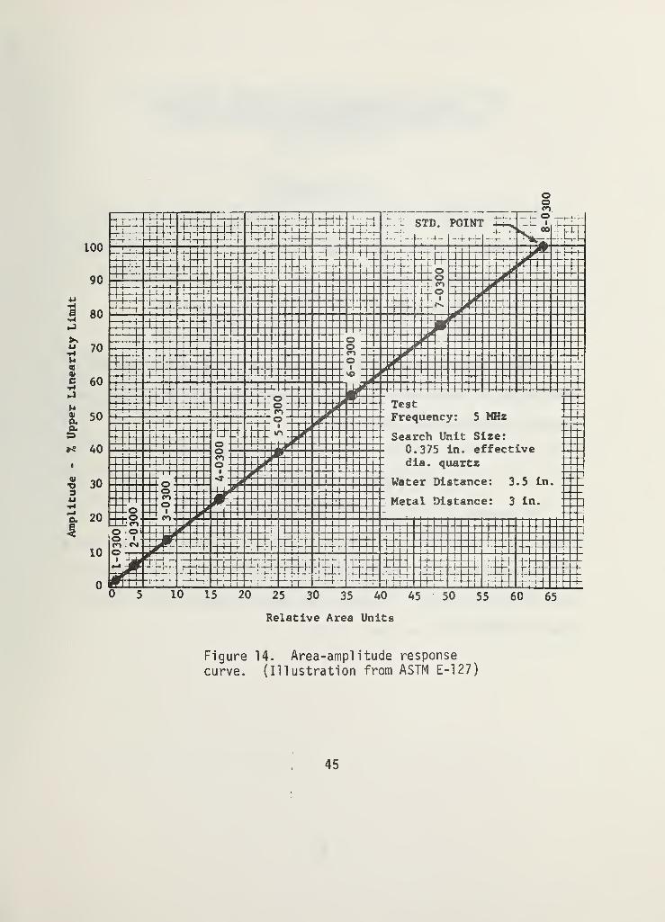
The blocks are characterized by their distance-amplitude and area-
amplitude responses (Figures 13 and 14). Ultrasonic differences between
the blocks and the inspected material should be considered when stan-
dardizing systems for inspection of aluminum products. There are three
41

standard sets: the basic set which consists of blocks with several hole
sizes and metal distances; the area-amplitude set with blocks of dif-
ferent hole sizes and equal metal distances; and the distance-amplitude
set which contains blocks with equal hole sizes and different metal
distances.
2.12.2 Evaluation
This standard is a very detailed description for fabricating and
checking aluminum reference blocks. These blocks are mainly used in the
United States as a primary reference source for evaluating the per-
formance characteristics of ultrasonic systems (see ASTM E-317, pages 38
and 39) and for the inspection of aluminum products.
The blocks used in Europe (i.e., I1W Blocks 1 and 2, pages 11-16)
and in the welding industry in the United States (see ASTM E-164, pages
48-53) are suitable for use with normal and angle-beam techniques, while
the ASTM flat bottom hole blocks are limited to the normal -beam tech-
nique only. The flat-bottom hole reflector has a linear area-amplitude
response (see Figure 14). This is an advantage when checking vertical
linearity of the system. An additional advantage is that the distance-
amplitude set provides a direct method for determining the DGS diagram
and the dead zone.
42

uX
2j' t .020” DIA^
25^5
n1
1
hitit
J±L
HOLE A, BOTTOM MUST BEFLAT WITHIN .001 IN. PER.125 IN. DIA. AND FINISHED SIZEMUST BE THE REQUIREDDIA. ± . 0005 IN.
THIS NUMBER INDICATES HOLEDIA. IN 1/64 THS, AND METAL,DISTANCE IN .01 IN. (SEETABLES 1, 2 AND 3)
HOLE MUST BE STRAIGHTAND PERPENDICULAR TOENTRY SURFACE WITHIN0° -30
' AND LOCATEDWITHIN .010 IN. OFLONGITUDINAL AXIS
FLAT COUNTER BORE
-
.250 DIA. X .064 IN. DEEP
BACKSURFACE
Figure 12. ASTM flat bottom hole referenceblock. (Illustration from ASTM E-127)
43

Figure
13.
Distance-Amplitude
Response
Curves
(A
and
B)
Showing
the
Interrelationship
between
Ultrasonic
Standard
Reference
Blocks
of
Various
Lengths
and
Containing
Flat-
Bottom
Holes.
(Illustration
from
ASTM
E-127).
Amplitude - 7« Upper Linearity Limit
Nio o-p'
o CTv 00o o
-0050
-0100
-0175
-0200
to
o
S' -0300(HI
0z
1h -0400
-0500
-0600
44
Amplitude
-
%
Upper
Linearity
Limit
Relative Area Units
Figure 14. Area-amplitude response
curve. (Illustration from ASTM E-127)
45
2.13 Standard Recommended Practice for UltrasonicAnql e-Beam Examination by the Contact Method,
ASTM E-587 (1976)
2.13.1 Synopsis
This recommended practice gives a very general description of a
broad spectrum of contact angle-beam techniques. It contains a brief
description of compressional , shear, surface wave and lamb wave modes
and how the different modes are generated in the material.
General instructions for distance and amplitude calibration and a
short guide for angle-beam examination techniques using single and dual
element transducers are given.
2.13.2 Evaluation
This standard is very general and is really more of a brief ex-
planation and description of contact angle beam techniques rather than a
procedure which can be directly applied to test or calibrate ultrasonic
flaw-detection systems. The angle beam method is described in greater
detail in ASTM E-164 (see pages 48-53).
46

2.14 Standard Recommended Practice of Steel ReferenceBlocks Used in Ultrasonic Inspection,
ASTM E-428 (1975)
2.14.1 Synopsis
ASTM E-428 is a recommended practice for fabricating and checking
flat-bottom hole blocks to be used for the testing of steel or other
metal products.
The procedures for fabricating and checking the blocks are similar
to those for aluminum blocks (see ASTM E-127 pages 41-45) with one
principal difference. The acoustic properties of the aluminum blocks
are checked against a steel ball reflector which serves as master
reference, while the properties of the other blocks are checked against
the properties of the inspected material. Blocks are usually fabricated
from the same materials as those which are to be tested.
2.14.2 Evaluation
(See evaluation of flat-bottom aluminum blocks ASTM E-127 page 42).
47

2.15 Standard Recommended Practice for UltrasonicContact Examination of Welds,
ASTM E-164 (1974)
2.15.1 Synopsis
This standard contains a very extensive description of calibration
procedures and reference blocks for testing welds using the contact,
normal and angle-beam pulse-echo techniques.
The standard describes a series of reference blocks most commonly
used in the United States and Europe, and it provides a variety of
techniques for the most conrnon types of system adjustment and stan-
dardization for weld inspection.
The following system parameters can be calibrated and checked with
the different blocks:
1. Horizontal linearity.
2. Range and transmission point (zero point).
3. Working sensitivity.
4. Transducer central beam exit point.
5. Angle of refraction.
48

6. Back-surface resolution.
7. Beam profile.
8. Distance-amplitude response.
The various blocks described in this standard are listed below:
1. IIW Block 1. A description of this block is given on p. 11.
2. AWS Distance Calibration (DC) Block: AWS Sensitivity
Calibration (SC) Block: AWS Distance-sensitivity Calibration
(DSC) Block (see Figure 15).
3. Angle-beam calibration blocks (see Figure 16).
4. ASME-type basic calibration block (see Figure 17)
J
All tests and calibrations are performed with an ultrasonic system
evaluated according to ASTM E-317.
Fabrication and use of ASME-type basic calibration block is describedin great detail in the ASME Boiler and Pressure Vessel Code: Section V.
Article 5; Section III, Appendix XVI; and Section XI, Appendix I.
49
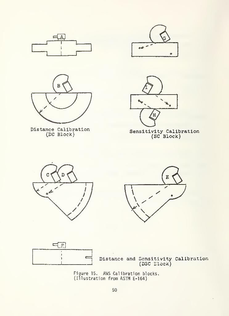
r*
Distance Calibration(DC Block)
Sensitivity Calibration(SC Block)
*=ra
Distance and Sensitivity Calibration(DSC Block)
Figure 15. AWS Calibration blocks.(Illustration from ASTM E-164)
50

Figure 16. Angle-beam calibration block.
51

3T MIN.
/"
t/’
!
4"
MlM
i *
.OZ T
^ Hole
Figure 17. Basic ASME calibration block and
some of its uses. (Illustration from ASTM
E-169)
52

2.15.2 Evaluation
This standard* designed originally for the examination of welds,
can actually be used for the examination of a variety of metal products.
It is a very extensive and detailed description of the most common
testing and calibration techniques used in the welding industry in the
United States and Europe.
The standard is very product oriented. The calibrations and checks
are performed with blocks made of the same material as the material to
be tested. This standard provides excellent guidance for establishing
specifications for weldments and other metal products. The presentation
is very detailed and contains many explanatory drawings.
53

2.16 Nondestructive Testinq, Welded JointsUltrasonic Method, GOST 14782-76 (1976)
2.16.1 Synopsis
In this standard, requirements for inspection of welds with the
contact, normal and angle-beam echo-amplitude techniques are given.
Methods for monitoring the following parameters are described:
1. Frequency.
2. Conditional sensitivity (defined below).
3. Ultimate sensitivity (defined below).
4. Angle of refraction.
5. Depth calibration.
6. Wedge angle.
7. Dead zone.
8. Resolution (the equivalent of time base calibration).
9. Point of exit of central beam (index).
10. Effective size of transducer.
11 . Pulse length.
The standard consists of six chapters. Chapter 1 deals with the
evaluation of general system parameters not related to a particular
test. Chapter 2 deals primarily with procedures for adjusting the
sensitivity of the system for a particular test and the remaining four
chapters deal with scanning methods for different configurations of
welds, interpretation and documentation of results and safety requirements.
54

The reference blocks are divided into two groups: "standard
blocks" (Figs. 18, 19 and 20) used to evaluate system parameters and
"test blocks" (Figure 21) for adjusting and checking the sensitivity of
the system for a particular test.
The system parameters evaluated in Chapter 1 are: depth (time
base) calibration, frequency, wedge angle, angle of refraction, reso-
lution, dead zone and conditional sensitivity. "Conditional sensitivity"
is expressed in millimeters of depth of the farthest detectable side-
drilled hole in the standard plastic block number 1 (Figure 18).
Conditional sensitivity is also expressed in decibels using the side-
drilled hole of the standard steel block number 2 (Figure 19) if the
instrument is equipped with an attenuator. This parameter characterizes
the threshold of detectability of the system. Other system parameters
determined with block number 1 are resolution, depth calibration and
wedge angle. Block number 2 is used to monitor angle of refraction,
dead zone and also to provide a depth calibration. Blocks similar to
the number 2 block, but made of materials other than steel, are marked
2A. Additional standard blocks, number 3, 4 and 4a made of mild steel
(Figure 20), are used to monitor the point of exit of the central beam
and the frequency.
The procedure for adjusting the sensitivity of the system for
a particular test, "threshold sensitivity" , is outlined in Chapter 2.
"Threshold sensitivity" is defined as the area in square millimeters
55

of the smallest detectable flat bottom hole located at a specified
depth, for a certain adjustment of the instrument. Blocks with flat
bottom and side-drilled holes and notches (Figure 21) are used to set
the "threshold sensitivity". Formulas to calculate the equivalent flat
bottom hole sensitivity if measurements are made with notch or side-
drilled hole reflectors are given.
2.16.2 Evaluation
Chapter 1 deals with rather basic parameters on which accuracy,
sensitivity, reliability and comparabil ity, namely the quality of a
pulse-echo technique test depend. It may be applied to other metal
products as well as to welds. In the Soviet Union this part of the
standard is apparently accepted as general guidance for checking and
calibrating ultrasonic test systems. Three of the ultrasonic product
standards reference the procedures outlined here. (See utilization
study, pages 60-61).
A failing of the standard is that it often requires determination
of parameters without describing the procedures. For instance, pro-
cedures for the calibration of depth and for the monitoring of frequency
and pulse length are not specified. Some of the blocks contain reflec-
tors, the use of which is not given. Highly qualified personnel might
be needed to transfer the general requirements of the standards into
working procedures.
56

Hi 20Vto
Figure 18. GOST standard block 1.
(Illustration from GOST 14782-76)
Figure 19. GOST standard block 2.
(Illustration from GOST 14782-76)
57

Figure 20. GOST standard blocks 3, 4 and 4a.
(Illustrations from GOST 14782-76)
58
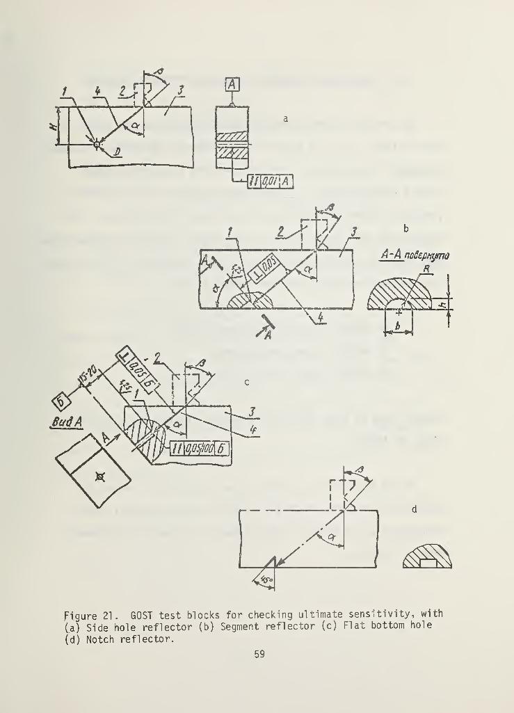
Figure 21. GOST test blocks for checking ultimate sensitivity, with
(a) Side hole reflector (b) Segment reflector (c) Flat bottom hole
(d) Notch reflector.
59

3. UTILIZATION OF GENERAL STANDARDS IN PRODUCT STANDARDS
One of the criteria by which general standards may be judged is
their utility, i.e., the extent to which they are referenced in product
standards. It was found in this phase of the study that not many
product standards exist. In most cases the ultrasonic inspection of
products is based on manufacturers' and buyers' specifications. For
instance the West German Standards Institution (Deutscher Normenausschuss
DNA), does not promulgate ultrasonic product standards. In France, only
three national ultrasonic product standards exist:
NF A04305 - inspection of steel plates;
NF A49200 - inspection of tubes;
NF A49870 - inspection of tubes.
However, none of these refer to the general standard for the IIW 1
Block, NF A04311
.
In the Soviet Union a similar situation exists. The Soviet
standards organization (USSR State Committee for Standards), which
promulgates a vast number of GOST standards, has very few ultrasonic
product standards.
60

GOST 14782 - for welds;
GOST 18576 - for railway rails;
GOST 21120 - for bars and billets; and,
GOST 12503 - for steel products;
GOST 22727-77 - for steel plates;
GOST 21397-75 - for aluminum products(flat-bottom hole calibration blocks)
GOST 14782 is also considered to be a general standard. Three of the
product standards reference procedures that are described in GOST 14782.
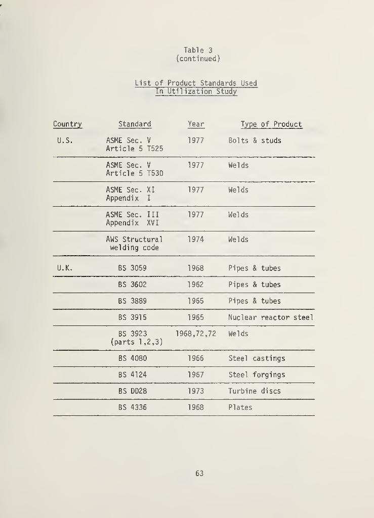
The United Kingdom and the United States have more ultrasonic
product standards. In this study nineteen ASTM, ASME and AWS
standards as well as nine BS standards were investigated. (See Table 3.)
The utility of the BS general standards is presented in Table 4. As can
be seen, six of the nine British product standards refer to the two
existing general standards. Table 5 shows that of the nineteen U.S.
product standards, thirteen refer or base their procedures on various
general standards.
61

Table 3
List of Product Standards UsedIn Utilization Study
Country Standard Year Type of Product
U.S. ANSI/ASTM A-388ASME SA-388
1978 Steel forgings
ANSI/ASTM A-435ASME SA-435
1975 Steel plates
ANSI/ASTM A-503 1975 Crankshaft
ANSI/ASTM A-577ASME SA-577
1977 Steel plates
ANSI/ASTM A-578ASME SA-578
1977 Steel plates
ANSI/ASTM A-609ASME SA-609
1978 Steel casting
ANSI/ASTM B-548ASME SB-548
1976 Aluminum plates
ANSI/ASTM B-594 1974 Aluminum wroughtproducts
ANSI/ASTM E-164 1974 Welds
ANSI/ASTM E-213 1977 Pipes & tubes
ANSI/ASTM E-273 1974 Pipes & tubes
ANSI/ASTM E-588 1976 Bearing quality steel
ANSI/ASTM A-418 1977 Turbine generatorsteel retaining rings
ANSI/ASTM A745 1977 Austenitic steel
forgings
62
r
Table 3
(continued)
List of Product Standards UsedIn Utilization Study
Country Standard Year Type of Product
U.S. ASME Sec. V
Article 5 T5251977 Bolts & studs
ASME Sec. V
Article 5 T5301977 Welds
ASME Sec. XI
Appendix I
1977 Welds
ASME Sec. Ill
Appendix XVI1977 Welds
AWS Structuralwelding code
1974 Welds
U.K. BS 3059 1968 Pipes & tubes
BS 3602 1962 Pipes & tubes
BS 3889 1965 Pipes & tubes
BS 3915 1965 Nuclear reactor steel
BS 3923(parts 1 ,2,3)
1968,72,72 Welds
BS 4080 1966 Steel castings
BS 4124 1967 Steel forgings
BS DD28 1973 Turbine discs
BS 4336 1968 Plates
63
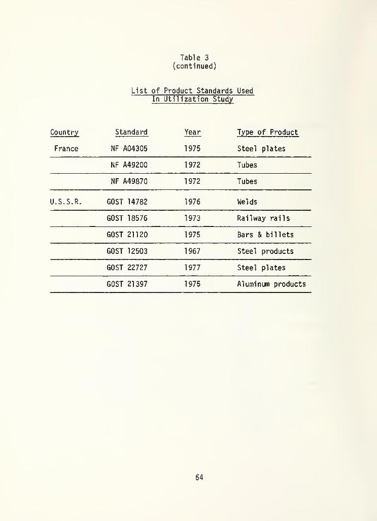
Table 3
(continued)
List of Product Standards UsedIn Utilization Study
Country Standard Year Type of Product
France NF A04305 1975 Steel plates
NF A49200 1972 Tubes
NF A49870 1972 Tubes
U.S.S.R. GOST 14782 1976 Welds
GOST 18576 1973 Railway rails
GOST 21120 1975 Bars & billets
GOST 12503 1967 Steel products
GOST 22727 1977 Steel plates
GOST 21397 1975 Aluminum products
64
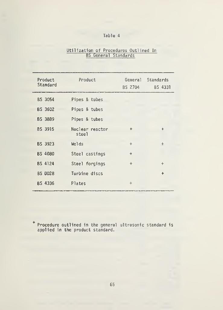
Table 4
Utilization of Procedures Outlined In
BS General Standards
ProductStandard
Product General
BS 2704
Standards
BS 4331
BS 3054 Pipes & tubes
BS 3602 Pipes & tubes
BS 3889 Pipes & tubes
BS 3915 Nuclear reactorsteel
+ +
BS 3923 Welds + +
BS 4080 Steel castings +
BS 4124 Steel forgings + +
BS DD28 Turbine discs +
BS 4336 Plates +
Procedure outlined in the general ultrasonic standard is
applied in the product standard.
65
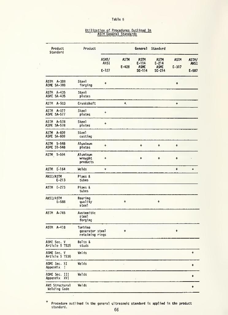
Table 5
Utilization of Procedures Outlined In
ASTM General Standards
ProductStandard
Product General Standard
ASNT/ ASTM ASTM ASTM ASTM ASTM/ANSI E-114 E-214 ANSI
E-428 ASME ASME E-317E-127 SE-114 SE-214 E-587
ASTM A- 388
ASME SA-388Steelforging
+ +
ASTM A-435ASME SA-435
Steel
plates
ASTM A- 503 Crankshaft +. +
ASTM A- 577ASME SA-577
Steel
plates+
ASTM A- 578A.SME SA-578
Steel
plates+
ASTM A-609ASME SA-609
Steel
casting
ASTM B-548ASME SB- 548
Aluminumplates
+ + + +
ASTM B-594 Aluminumwroughtproducts
+ + + + •
ASTM E-164 Welds + + +
ANSI/ASTME-213
Pipes &
tubes
ASTM E-273 Pipes &
tubes
ANSI/ASTME-588
Bearingqualitysteel
+ +
ASTM A- 745 Austeniticsteel
forging
ASTM A-418 Turbinegenerator steel + +
retaining rings
ASME Sec. V
Article 5 T525Bolts &
studs
ASME Sec. V
Article 5 T530Welds +
ASME Sec. XI
Appendix I
Welds +
ASME Sec. Ill
Appendix XVI
Welds +
AWS StructuralWelding Code
Welds +
* Procedure outlined In the general ultrasonic standard Is applied In the productstandard.
66

4. DISCUSSION
There are two different approaches which can be taken in the
philosophy of formulating general ultrasonic testing standards. One is
to establish "universal" measurement standards, against which all cali-
brations will be based. The other is to establish special reference
standards for each specific case. The formulation of most general
ultrasonic testing standards is usually a compromise between these
approaches. In the United States the tendency is more toward the
"universal" approach, while the European general standards are usually
more "specific" and product oriented.* For instance, European standards
usually do not require a general evaluation of the ultrasonic system as
outlined in ASTM E-317. Usually, only a calibration and adjustment for
the particular work in hand, as outlined in DIN 54120 and similiar
standards, are required.
* In Europe an attempt also has been made by IIW and by ISO to prepare
standards of a "universal" nature for the evaluation of systems and
components. Some of the working documents include IIW VC-236-72/DE, ISO
135/2/WG 1 on Characterization of Equipment - West Germany; ISO-1973
Proposal on Characterization of Systems and ISO TC-310-75 on Search-unit
Characterization - The Netherlands.
67

The potential advantage of general procedures and the characterization
of ultrasonic systems is that it leads to universal comparability
standards for systems and products. By determining an absolute system
response characteristic, the only remaining unknown variable will be the
actual ultrasonic response of the tested product. On the other hand,
the "specific" general standards are limited to specific conditions.
Unfortunately, most of the parameters are influenced by the properties
of the tested material, the system component characteristics (apparatus
and transducer) and the working conditions. These influences usually
cannot be analyzed independently. Therefore, when testing hardware
items, special and detailed specifications have to be used.
Since an absolute response characteristic is not yet attainable,
European standards usually depend on the characteristics of systems
which were established under conditions simulating the conditions of the
work at hand (the "specific" approach). The following citations from
European standards will illustrate the philosophy of the European
standards community as it applies to ultrasonic testing:
(1) BS 4331 Pt. 3 1974 .-- "Where probes or instruction on
procedures are issued from a central source, it should be
remembered that characteristics of equipment on site may
sometimes differ significantly from those of the master test...
68
"Since the properties here referred to as probe
characteristics are in fact influenced by the acoustical
and electronic characteristics of the system as a whole
(and including certain characteristics of the work piece),
it is essential that all checks are carried out with the
testers own flaw detector and under conditions as nearly
as possible identical with those involved in the particular
work in hand. .
.
"
DIN 54120 - 1973 - "Since it is essential to take account
of the specific properties of the equipment and the test
conditions, it is not possible, without further information,
to state an absolute index of indication sensitivity which
is universally true."
It seems that differences in the definitions of some terms and the
use of different reference reflectors stem from this difference between
the American and the European philosophies of standardization.
The different concepts can be illustrated by comparing the defi-
nitions of the term sensitivity in the U.S. standard ASTM E-317
("universal" concept) and in the West German standard DIN 51220 and the
British standard BS 2704 ("specific" concept). Although the meaning of
sensitivity is the same in all three standards and it is always related
to the smallest detectible reflector, its definition and formulation is
69

different. In ASTM E-317, ultrasonic sensitivity is a parameter of the
system itself, independent of the specific work to be performed. It is
calculated from the ratio of the maximum height of the echo-amplitude
obtained from ASTM block 1-0300 and the upper linearity limit. In the
European standards independent system sensitivity is not determined.
Only equipment sensitivity and sensitivity of indication related to
specific work are determined. The sensitivity of indication is explored
on the test piece itself and then standardized against a standard
reflector in order to check and readjust the system. This same concept
is used in American product standards (e.g., ASTM E-273 for spiral
welded pipes, A-388 for steel forgings, etc.). When comparing standards
from different sources, differences in definition, formulation and
terminology should be considered.
Apparently, the use of different reference reflectors in the
general standards in the United States and in Europe is also connected
with the different concepts of standardization. In the United States,
primarily flat-bottom holes are used as reference reflectors (see
ASTM E-127, E- 31 7 and E-428). These have a linear area-amplitude re-
lationship which makes the general evaluation of systems simpler and
permits direct determination of D6S diagrams. In Europe, however,
where the system is usually calibrated in conjunction with specific
work, the most commonly used reference reflectors are side-drilled
70
holes. These are simpler to fabricate and in some cases, especially in
welds and castings, they more frequently resemble real flaws of spherical
and cylindrical shapes. When testing hardware items, especially welds,
the side-drilled hole is the commonly used reference reflector in the
United States (ASME basic calibration blocks) as well as in Europe.
- ! . . i'
4.1 Summary of Discussion
In the U.S. the "general" approach and the flat-bottom hole
standard reflector is used more often, while in Europe the "specific"
approach and the side-drilled hole reflector is preferred. This
division, however, is not very distinct. Many European standards such
as GOST 14782-76, 12503-67 and 21397-75, BS 2704 and D.D28 have used
flat-bottom hole reflectors. In the U.S. the side-drilled hole has been
utilized in ASTM E-164 and E-587, in ASME specifications for the exami-
nation of welds and plates, and in the AWS welding code. The "general"
approach utilized in the evaluation of ultrasonic testing systems in
the U.S. (see ASTM E-317) can also be found in BS 4331 part 1. Other
standards for the general evaluation of systems are in preparation by
ISO and IIW (see footnote p. 66). It seems that due to the flow of
information, and the international standardization activities of ISO and
IIW, the differences are tending to become less distinct.
71

References
1. R. S. Sharpe, M. A. Cole and W. C. Hesetwood, Quality TechnologyHandbook - pp. 306-334 (JPC Science and Technology Press Ltd. 1975).
2. J. Krautkramer and H. Krautkramer, Ultrasonic Testing of Materials ,
2nd Edition pp. 600-604 (Springer-Verlag, Berlin, Heidelberg,New York, 1977).
3. Commonly Used Specifications and Standards for NondestructiveTesting, Materials Evaluation , Vol . 29, No. 5, p. 17A (May 1971).
72

NBS-114A (REV. 8-78)
U.S. DEPT. OF COMM.
BIBLIOGRAPHIC DATASHEET
1. PUBLICATION OR REPORT NO.
NBSIR 79-1790
4. TITLE AND SUBTITLE
A Comparison of American and European UltrasonicTesting Standards
7. AUTHOR(S)
Sam Golan
8. Performing Organ. Report No.
9. PERFORMING ORGANIZATION NAME AND ADDRESS
NATIONAL BUREAU OF STANDARDSDEPARTMENT OF COMMERCEWASHINGTON, DC 20234
10. f^Jed/Tasfc/Worfc tfnit No.
11. Contract/Grant No.
12. SPONSORING ORGANIZATION NAME AND COMPLETE ADDRESS (Street. City. State. ZIP) 13. Type of Report & Period Covered
IS. SUPPLEMENTARY NOTES
I |Document describes a computer program; SF-185, FIPS Software Summary, is attached.
16. ABSTRACT (A 200-word or teas factual summary of moat significant information , If document includes a significant bibliography or
literature survey, mention it here,)
In this work twenty-seven general ultrasonic standards from eleven countriesand international organizations were reviewed. Thirty-seven ultrasonic productstandards from five countries were studied to evaluate the utilization of thegeneral ultrasonic standards, i.e., to what extent the procedures outlined in thegeneral standards are applied by the product standards.
17. KEY WORDS (a ix to twelve entries; alphabetical order; capitalize only the first letter of the first key word unless a proper name;separated by semicolons)
Evaluation; international; standard recommended practice; standardization;synopsis; ultrasonic standards; ultrasonic testing.
18. AVAILABILITY H71 Unlimited
I |For Official Distribution. Do Not Release to NTIS
I IOrder From Sup. of Doc., U.S. Government Printing Office, Washington, DC20402, SD Stock No. SN003-003-
I IOrder From National Technical Information Service (NTIS), Springfield,
VA. 22161
19. SECURITY CLASS(THIS REPORT)
UNCLASSIFIED
20. SECURITY CLASS(THIS PAGE)
UNCLASSIFIED
21. NO. OFPRINTED PAGES
74
22. Price
$5.25
USCOMM-DC

mmmmm