A Basis for Modelling Ceramic Composite Armour Defeat
44
co 0 ID FOP 9 U, ,I , , -0 l I I I Il• II I iI I i i i
Transcript of A Basis for Modelling Ceramic Composite Armour Defeat

co0ID
FOP 9 U, ,I , ,
-0 l I I I Il • II I iI I i i i
A BASES FOR MODEINMG CERAMIC COMPOSITE
ARMOUR DEFEAT
Raymond L. Woodward
MRL Research ReportMRL-RR-3-89
ABSTRACT
This work takes some of the major features of ceramic composite armourfailure, viz. fracture conoid formation, dishing failure of thin backingplates, perforation failure of thick backing plates, and projectile erosion,and by lumping masses to treat material acceleration simple models aredeveloped which allow computations on ceramic targets with both thin andthick metallic backings. Two computer programs for these problems, CEPand ECS, are documented, and calculations compared with a broad range ofempirical data and also used to discuss aspects of the interaction ofpenetrators with ceramic composite armours. The good correlation ofmodels with experiment demonstrates the usefulness of the presentapproach for studying ceramic composite armour defeat.
Accesion For
NTIS CRA IxDTIC TAB 0LI d :Io 0
By .... .............. .
Ditbt
DIst AvI 11 oru
__- -89 11 -1 Ug34i i IOIl
Published by DSTO Materials Research LaboratoryCordite Avenue, Maribyrnong, Victoria 3032, AustraliaTelephone: (03) 319 3887Fax: (03) 318 4536
@ Commonwealth of Australia 1989AR No. 005-713
Approved for public release
$CONTENTS
I
Page
1. INTRODUCTION 5
I2. APPROXIMATE NUMERICAL CONSIDERATIONS 6
3. MODEL DEVELOPMENT 7
4. SELECTION OF MATERIAL STRENGTH DATA 13
5. COMPARISON WITH EMPIRICAL DATA 14
6. DISCUSSION 18
7. CONCLUSIONS 19
8. REFERENCES 19
APPENDIX 1 CEP - Computer Program for Thin Backing CeramicComposite Targets
APPENDIX 2 ECS - Program for Ceramic Perforation whenBacked by a Thick Plate
d
A BASIS FOR MODELIJNG CERAMIC COMPOSITE
ARMOUR DEFEAT
1. INTRODUCTION
The development of ceramic composite armours rests soundly on the basis of the work ofWilkins et al. [1-3] who developed the commonly used configuration of ceramic tilessupported by a thin ductile backing material. Wilkins used the HEMP finite differencecomputer code to simulate ballistic experiments, and although a complete description of anevent through to perforation was not possible, he was able to isolate many of the importantfeatures of the penetration problem. The ceramic tile was seen to load the projectile nosecausing attrition and deceleration, at a rate governed by the yield strength of the projectilematerial. The ceramic fractured in the form of a conoid followed by tensile failure in theceramic initiating at the ceramic/backing plate interface, opposite the impact location.Wilkins proposed that delaying the initiation of tensile failure would substantially increasethe performance of ceramic composite armours by allowing more projectile erosion.
There has been substantial interest recently in empirical studies of the failure ofceramic armour. Mayseless et al. [4] present data for targets with a range of thin backingplate materials, and also for cases where no backing is used. The backing is shown tocontribute substantially to the achievement of good ballistic performance in the ceramic.Rosenberg et al. [5, 61 have used effectively semi-infinite backings and measured residualpenetration depths into these as a guide to ceramic performance. They conclude thatballistic performance increases with increase in effective compressive strength of theceramic.
Studies by Nicol et al. [71 of the energy distribution in the defeat of glass andceramic tiles backed by thin aluminium plates, using small calibre armour piercingprojectiles, demonstrated that a negligible proportion of the projectile's kinetic energy wentinto fracture of the ceramic. The major energy dissipating mechanisms were identified asplastic deformation of both the backing plate and the penetrator and as kinetic energypicked up by the ceramic debris and the supporting structure. The backing plates forceramic targets were not defeated by perforation, but rather bulged and necked to failureby ductile fracture. In the case of glass tiles the projectile core was not deformed anddefeated the backing plate by perforation.
While cone cracking has been studied extensively 18-121 in semi-infinite glassmedia, it has been studied less extensively in finite thickness bodies [13]. The ideal coneangle depends on the elastic properties of both indenter and brittle material [91, but forquasi-static ball indentations is generally around 68' to the axis of indentation. Undercontrolled dynamic conditions the crack travels through a time varying stress field and

hence significant, but predictable, departures from the ideal angle are observed [91.Ballistic impact tends to be an overload situation with little control and therefore it isextremely difficult to study the sequence of cracking. Nevertheless the cone shaped zoneof damage simulated by Wilkins 131 is similar to observed fracture conoids and at similarangles to cone cracks seen in quasi-static indentation of glass plates. Hornemann et al.1141 have used high speed photography to study crack propagation in the ballistic impact ofglass plates. They observe not only the propagation of cracks from the impact site but alsothe nucleation and growth of cracks in the stress field ahead of the damage front. In thephotographs of impacted glass of Pavel et al. [151 the fragmented glass debris is ejected ata similar velocity to the rate of penetration by the projectile.
The experimental and computational studies leave many gaps in ourunderstanding of the perforation of ceramics. This work presents approximate modelsolutions which allow computations on ballistic impacts into ceramic composite armours,with both thick backing and thin backing, relative to the projectile calibre. The cone crackformation, ceramic and projectile erosion and backing deformation as well as the inertialresponse of the system components are realistically modelled. The principal observedfeatures associated with trends in ballistic performance with changes in ceramic andbacking thickness, ceramic and backing materials, projectile type and impact velocity areobserved in the computational results. Predictions are generally of the correct magnitudeand in many cases quite accurate. The solutions allow the mechanical principles to bestudied, and can direct attention to those aspects, such as ceramic strength propertiesrelevant to cracking and erosion, which need to be more closely studied.
2. APPROXIMATE NUMERICAL CONSIDERATIONS
Figure 1 shows the computer simulation of the impact of a steel penetrator on a ceramiccomposite target which Wilkins 131 demonstrated was close to the observations on flashradiographic images of an experimental trial. The sequence of figure 1 can be used forsome approximate calculations which are instructive in guiding the modelling of such anevent. From the deceleration of the projectile and its mass one can calculate the forceretarding the rear of the projectile as around 100 kN which is close to the yield force of91 kN, estimated from the projectile hardness and cross sectional area. One can concludereasonably therefore that the force retarding the projectile is governed by plastic yieldingof the projectile where it interacts with the ceramic, as did Wilkins 12].
In the region bounded by the cone crack, the use of a triangular velocity profile,and estimation of the mass of ceramic and metal being accelerated, gives a resultant forceaccelerating the target material of about 130 kN. The force acting on the target materialdue to impact is the yield force of the projectile (about 100 kN estimated above) plus thechange in momentum according to Tate's [161 approximate theory of penetration. From themass loss the estimated force due to a change in momentum is 53 kN, giving a total forceacting on the target of 153 kN. The force resisting plate an.celeration is the total forceacting, 153 kN, less the resultant, 130 kN, or about 23 kN. If the ceramic is assumed topresent no strength along the cracked conical boundary one can use simple plasticitycalculations to estimate from the flow stress of the aluminium that the resistance offeredby the backing is 100 kN if it came from shear at the periphery of the conical region or 33kN if it came from dishing deformation. From these approximate computations it istherefore possible to state with a high degree of confidence that resistance to thepenetrator is provided by inertia of the ceramic and backing bounded by the cone crack, andby dishing deformation of the backing. Using such simple calculations it is also possible toshow that at the time when the projectile has decelerated and target material acceleratedto a common intermediate velocity, the displacement of the back of the target is only a few
6

millimetres, in contrast to final deflections of 15 to 25 mm observed in typical perforatedaluminium backing plates. The conclusion therefore is that the second stage of perforationinvolves the penetrator and target material bounded by the cone, moving forward resistedby bending and membrane forces in the backing till either they are slowed to zero velocityor rupture of the backing occurs. These concepts form the basis for modelling theperforation of ceramic composites with thin backing plates.
In figure 1 the simulation shows evidence of a decrease in ceramic thicknesswith time, erosion, and some criterion for estimating the load at which the ceramic iseroded is required. The rate of erosion will be determined by yielding and cracking beneaththe penetrator. Quasi-statically a blunt indenter forced into a ceramic causes yielding andfracture and the pressure beneath the indenter is a measure of hardness of the ceramic.Continued quasi-static indentation requires a pressure equal to the material hardness.Figure 2 shows a typical Vickers indentation in an alumina tile where cracking is evidentfrom the corners of the indent. If ceramics are assumed to obey the same laws of plasticflow as metals then the uniaxial flow stress can be obtained approximately from thehardness by dividing by 2.9 [171. Pavel et al. [151 show the reduction in velocity of aneffectively non-deforming penetrator fired through glass. The velocity reduction expectedcan readily be calculated assuming the force resisting the movement of the penetrator issome factor of the uniaxial yield stress of the glass, as estimated by dividing the hardnessby 2.9, and taking account of the fact that approximately one calibre at the back of theglass plate is ejected with negligible resistance. Such computations are compared with theempirical data of Pavel et al. [15] in figure 3, where it appears the resisting force isreasonably taken as the uniaxial flow stress of the glass. For a metal perforated by apointed projectile it would be twice that flow stress [181, and if the flow pressure was equalto the hardness of the ceramic then a larger deviation from experiment would be expectedin this instant. An equivalent experiment for a ceramic is not available, and typicalceramic toughnesses are significantly higher than those of glass [19] indicating that chippingmay be expected at a somewhat higher pressure in ceramics. The appropriate pressure atwhich ceramic erosion takes place is thus expected to be somewhere between the uniaxialflow stress and the hardness, but is left open for detailed comparison of computations withexperiment for actual targets.
3. MODEL DEVELOPMENT
(a) Physical Concepts and Assumptions
The main features associated with perforation of a ceramic armour with a thinbacking plate are shown schematically in figure 4(a). In modelling the process it wasassumed that crack propagation was sufficiently fast compared to the projectile velocitythat the cone crack separates the loaded region inside the cone from an unloaded regionoutside the cone. Based on the approximate calculations outlined previously the ceramicinside the cone and the backing plate bounded by the base of tne cone are acceleratedforward with a velocity profile allowing compatibility with both the flat ended projectileand the dishing of the backing plate. As shown in figure 4(b) the more realistic velocityprofile was slightly modified for computational efficacy in the model, the effect of thischange being negligible as the base diameter of the cone is generally far greater than theprojectile diameter. Because of the lack of knowledge on cone angle as a function ofimpact parameters, it was decided to use an angle between the normal to the ceramicsurface and the cone side of 68" for all computations, at least consistent with quasi-staticobservations on simple systems.
7
At the front of the penetrator erosion of projectile material is taking place. Inpractice with brittle penetrator materials this may be in "chunks", however as the physicsof such an attrition process is not developed it was assumed that projectile erosion, whetherby a cracking or a shearing mechanism, was governed by plastic flow of the penetratormaterial. Similarly if the velocity is high enough, yielding and fracture of the front of theceramic will be observed. This is again considered as leading to erosion of ceramic incontact with the projectile, governed by the normal load which the ceramic can sustain,whether this is estimated by indentation hardness or by uniaxial flow stress as discussed inparticular cases below.
The lumped parameter model for the inertial response of the system isrepresented in figure 4(c). In any time step At a mass AM and a mass AM of projectile andceramic respectively are eroded. M is the oncoming proectile mass anFM T the mass oftarget being accelerated. Force F ?esists forward movement of the projectile and Fresists acceleration of the target. IFc is a measure of the strength or collapse load oftheceramic and at the interface F, is determined by ceramic and penetrator strengths and therate of ceramic and penetrator erosion. After some time of interaction a number ofconsequences can ensue, viz. The system can slow to zero velocity stopping the projectileor the projectile can be completely eroded and thus stopped. The ceramic can be eroded tozero thickness and if there is still a velocity difference between the projectile and thebacking the projectile may perforate or, if there is no residual velocity difference, thebacking may continue to bulge till either the velocity is reduced to zero or bursting of thebulge occurs. Without complete ceramic erosion the components may come to someconstant intermediate velocity and perforation occur if the residual momentum is sufficientto continue bulging of the backing plate and cause rupture. The model for ceramiccomposite armours with thin backing is divided into two stages which treat targetacceleration using the model of figure 4(c), followed by an examination of target failure.
(b) Target Accelerativ
The equations of motion of the system in figure 4(c) are:
F = -1U (a)
F - F = - AMJ /At 1(b)I P PP
F - F = -AMUf /At 1(c)C I CC
FT - FC = r r 1(d)
where F is force,
M is mass,
At is the time increment,
U and U are velocity and acceleration respectively,
and subscripts P, I, C and T refer to penetrator, interface,ceramic and target respectively as in figure 4(c).
8
Each of the equations (1) relates the force on an element to the change inmomentum by either acceleration, U, or mass change, AM. The sign in equation (1b) is suchthat if F, > Fp, AMp is negative, i.e. there is a mass loss from the penetrator. The sign inequation (1c) is such that if FI > FC, AMJO is positive, i.e. there is an increase inmomentum of the ceramic material whI c is moved out of the way. At the interface theapproach of the penetrator and target in time step At is related to the loss in mass ofpenetrator and target. As a flat ended cylindrical penetrator of cross sectional area Ao isbeing treated, we can imagine a column of penetrator and ceramic being squeezed outgiving continuity equations of the form:
AMlp A = - (U -UJ) At 2(a)P Po P C
AMlp A = (UJ -UfJ) At 2(b)C Co C T
where p is the material density.
Constitutive equations for the failure of penetrator and ceramic can beestablished by requiring that for erosion of a column of material to occur, a value of flowstress, Y, must be exceeded, whether this is governed by uniaxial yield stress, hardness orsome other measure of strength. Then for erosion to occur
Fp = Yp Ao 3(a)
FC = YC Ao 3(b)
In the course of solving the equations, erosion of both ceramic and penetrator did notnecessarily occur; erosion requires that FI in equation (1) exceed the relevant force Fp orFC.
Equations (1) to (3) represent a very simplified concept of the interaction, withgross assumpticns on the lumping of elements of material i~ito composite masses. The viewof ceramic compression in a simple column is expedient and the issue of failure or erosionstress level for the ceramic must be addressed. The contribution of radial inertia toprojectile deceleration is ignored, as it is difficult to include in the form developed byJohnson [19], as erosiuii in a single front element leads to the force becoming unrealisticallylarge as the time step. and hence the height of that front eroding element also, becomessmall. Elimination of U and A M from the equations yields a quadratic which can besolved at each time stepfor the on y unknown parameter, the penetrator mass loss AMP.At each time step all other parameters can be updated and the solution then repeated. Arelationship is required for the resistance of the target backing to bulging, FT, and for anappropriate mass distribution to give the effective mass MT.
Woodward et al. 1201 derive an equation for the work, W, to dish a plate ofthickness b and flow stress YT to a displacement h,
2 1W = nbh YT (9 b + - h) (4)
and it is shown that this equation gives reasonable estimates of the work done on dishedbackings from actual impacted ceramic composite targets, when compared with the workcalculated from measurements on the plate profile. In deriving equation (4) it was assumed
9

the dish was in the form of a cone for calculation of stretching work, a yield moment wasassumed for bending, and it was noted that the work done in tangential curvature in theconically dished region equals the work done in radial curvature (Johnson [211). The forceresisting dishing is thus obtained by differentiating equation (4) to give
F = 7b YT (2 b + h) (5)T3
If M and MB represent masses of elements of ceramic and backing travelling atvelocities C ani C respectively then the total momentum of the backing is obtained bysumming thC momenta of individual elements. If the velocity of target material beneaththe penetrator is 0 then the effective mass of the target material, MT, can be defined by
MUi I zMUi + IMUf (6)TT CC BB
For the modified velocity distribution represented in figure 4(b) combined with the massdistribution of the ceramic cone and backing in figure 4(a), the effective mass becomesapproximately
Mr = TD 0(pc c/2 + PBb)/12 (7)
where Do is the base diameter of the cone,c is the ceramic tile thickness,
and other symbols and subscript notation are as used before. In cases where ceramicerosion occurred, the mass distribution was allowed to shrink in a geometrically similarmanner, with the velocity dropping to zero at the new outer boundary of cone intersectionwith the backing. Thus D in equation (7) simply reduces to a new diameter proportional tothe new height of the conical section. This approximation takes some account of thereduced target mass being accelerated and the reduced area of backing material which issubjected to bending and stretching loads.
(c) Target Failure
Two target failure possibilities are considered in order. For the first involvingductile instability in the backing plate, the situation after the phase of accelerating thetarget material is depicted in figure 5(a) with ceramic still separating the projectile fromthe backing plate and with projectile and backing moving forward at the same velocity. Inthis situation bulging of the backing plate will continue with the kinetic energy of thesy, tem being dissipated in plastic deformation of the backing, terminated by either areduction to zero velocity or rupture as in figure 5(b). In practice the hinge in the backingplate may be expected to move radially and substantial elastic deflections occur,particularly in thin plates. These aspects are, however, not easily treated. The simplifiedapproach used to obtain a solution considers the bulging plate as ideally plastic, with thehinge located at the cone base and uses equation (4) to calculate the work done.Perforation occurs if there is sufficient kinetic energy left in the projectile, ceramic andbacking after the acceleration phase to continue plate bulging to rupture. Thus a bulgeheight at plate rupture is required, i.e. a failure criterion.
Backing material stress/strain properties were curve fit to an equation of theform
10
-na = A+Be (8)
where a and e are ef'"ctive stress and strain, and A, B and n are constant curve fittingparameters for the material. The strain at instability, e i. in a biaxial tension test canthen be obtained Ly solving the equation
n+l
lIB e. - 4(2n + l)Ben + 11A e. - 4A = 0 (9)1 1 1
which is a variation on the form used by Johnson and Mellor [221 because of the differentcurve fitting relationship for stress and strain, equation (8). Equation (9) is easily solvediteratively by computer. For hydraulic bulging of circular plates the strain at instabilitycan be related to the displacement using the assumption that the particles in the membranedescribe circular paths. For the velocity profile of figure 4(b), the backing plate is going todeform into the shape of a cone. For simplicity it was assumed that the cone is uniformlytapered from the instability strain at the centre, e. , to the thickness of the original plateat the cone diameter Do . Then if e is the angle bitween the base and side of the cone, asin figure 5(b), constant volume deformation requires
e. = 2n (3 os e - 2) (10)
Thus from the material characteristics, equation (8), the instability strain is calculatedusing equation (9), which is substituted into equation (10) to obtain the angle through whichthe sides of the cone are bent at failure. From simple geometry the displacement, h, ofthe cone is calculated and this is substituted into equation (4) to calculate the dishing work.
If ceramic erosion has occurred during the target acceleration phase then thearea of the backing loaded will be reduced as discussed earlier. The assumed reduceddimensions of the cone and loaded backing after the target acceleration stage are shownschematically in figure 5(c), in relation to the initial dimensions. The velocity profile isshown in figure 5(d), where it is assumed for computational ease that the velocity drops tozero at the reduced outer hinge diameter, DR. The reduced diameter combined with thedeflection angle at failure from equation (10O leads to a lower failure displacement andhence work done in dishing failure using equation (4), than would be the case if no ceramicerosion occurred. It was assumed that only the momentum of the projectile, the ceramicand the backing material within the reduced dimensions acted to continue bulging. Thususing the simpler velocity distribution of figure 5(d) the effective kinetic energy, EK, toequate to the work done by equation (4) is
2D U
1 .2 , R T 2E = -MU + - (p c/5 + p b/3) ( ) (11)K 2 PP 80 D -DR P
where the ceramic thickness c is the reduced thickness after erosion, and D is thepenetrator diameter. The effects of using reduced dimensions when accounting for theeffects of erosion will be discussed in considering sample computations.
11

ImIf the ceramic is eroded to zero thickness during target acceleration, then a
projectile of higher relative velocity bears on the backing material and an alternativesecond failure criterion is needed. For failure it was considered the velocity at which thebacking was moving did not contribute to perforation and that it was the difference inprojectile /target velocity which allowed perforation. Thus the equation to determine
whether the penetrator would perforate in this case was
1 .2 2-M (U - ) = 7 D b Y /2 (12)2 P B P P T
where YT is the target flow stress, and subscript B represents backing. The methodassumes a simple ductile hole formation mode of failure and the equation is due to Taylor[23, 181.
The set of equations described for the acceleration and failure stages waswritten into a computer program, CEP, which treats perforation of ceramic compositetargets with thin backing plates. The program is listed in Appendix I with typical input andoutput. Examples of computations performed with the method are compared withexperimental data below.
(b) Composites with Thick Backing
For cases with very thick backing materials it was found that the ceramic canbe completely eroded with a relatively small increase in velocity of the backing. Inaddition the treatment of thick plate perforation with a dishing model is inappropriate.Therefore a simplified model for the first phase was developed where the interaction of thepenetrator and the ceramic only are considered, with the thick backing remainingstationary. The residual penetrator, after eroding the ceramic, then interacts with thebacking using a plugging model for finite thicknesses or a deep penetration model foreffectively semi-infinite backings. The method also has the advantage of allowing directchecking of the ceramic erosion model against data of the typ. produced byRosenberg et al. [5, 61 using semi-infinite targets.
The concept of interaction with a thick target is shown in figure 6(a) and thelumped parameter model is illustrated in figure 6(b). It is assumed that spreading of theload by the ceramic conoid is sufficient to allow negligible yielding of the backing plate.Then for a very large effective target mass MT we obtain
U =U =0 (13)'1 T
so that the solution of equations (1) to (3) becomes trivial. There is no requirement for aresisting force of the backing (FT). A computer program ECS was written which solves thesimplified equations and is listed with typical input and output in Appendix II. In runningthe program, depending on the input parameters the penetrator can be stopped before theceramic is eroded, the penetrator can be completely eroded before it perforates theceramic, or the ceramic itself can be eroded to zero thickness. In the latter case theoutput lists the residual average projectile mass and velocity.
Using the output from ECS, the plugging program PLUG [24, 251 can be used tosee if a thick backing is perforated by plugging by E flat ended fragment, or the programSLAM 126, 271 can be used to calculate the residual depth of penetration into a semi-infinite
12

metal target. An alternative simpler approach is to use the equation
1 .2 < 2-M -- D Y b (14)2 PP 2 P T
to relate the residual kinetic energy (LHS) to the work done in ductile hole formation(RHS). Here the symbols are as used before, except that b is the thickness of a finitebacking in which case the inequality determines whether penetration occurs, or for a semiinfinite target b becomes the depth of penetration using the equality. Equation (14) usesthe simpler Taylor model of ductile hole formation [23, 181 and is equivalent to equation(12) for the thinner targets. This last approach is expected to be less accurate for theblunt fragments exiting from the ceramic and was not generally used in this study, howeveris presented as it is a useful simpler form. The most satisfying aspect of the models forthin and thick backings is that when the same strength, YC, is used for the ceramic, it isobserved that thin target and thick target approaches tie together well at the transitionwith increasing backing thickness. The most significant approximation, which preventsextension to very high velocities is the neglect of radial inertia which has not been includedfor the same reasons it has not been included in the thin backing model, i.e. amathematically suitable treatment is not available.
4. SELECTION OF MATERIAL STRENGTH DATA
The penetrator undergoes large strain plastic flow on impact with the ceramic, thus a figurefor ultimate tensile strength can be used in the modelling of its deformation. Because inmany cases penetrators impacting a ceramic are hard, they are materials where there islittle work hardening and within the accuracy of the model a figure for yield stress or theapproximate equivalent, Diamond Pyramid Hardness divided by 2.9 [171, should also besatisfactory. Work hardening is not included in the model so the response of the penetratoris determined entirely by its assumed ideal rigid/plastic resistance to plastic flow.Diamond Pyramid Hardness data is simple to obtain.
The metallic backing material has a failure strain dependent on its workhardening properties, and backing mate. ial stress strain data was therefore fitted toequation (8) for the thin target probl ,n. For the thick backing or semi-infinite backingproblems, curve fitting of the backing material and projectile data to appropriate forms forthick target penetration models was also required [24-27).
The major decision involves the selection of a suitable strength level for theceramic representing its resistance to the penetrator or resistance to ceramic beingdisplaced or eroded. Quasi-statically the resistance to indentation is given by the DiamondPyramid Hardness, which is a stress, easily measured, figure 2, and ideal for use as ameasure of ceramic strength in the model. Alternatively it has been shown that the glasspenetration data of Pavel et al l13, figure 3, is well fitted if a flow stress determined ashardness divided by 2.9 [171 is utilized. Initial computations using some data presented byMayseless et al. 141, figure 7, show an underestimate of the 12.7 mm Berkeley data, howeverthe computations also showed the ceramic was not eroded under these conditions so therewas no test of the appropriate flow stress properties of the ceramic. The comparison withthe 7.62 mm data of Wilkins given in the same work indicates an underestimate if hardness
13
* -- --- - -, ~ ' ~-.- - -
divided by 2.9 is used as the ceramic flow stress and an overestimate by about the sameamount if hardness is used, figure 7(a). The separation into two distinct slopes of the plotsof theoretical curves for Wilkins experiments in figure 7(a), particularly noticeable for thelower strength level computations, is due to the onset of erosion at the higher backingthickness, where the impact velocity to cause perforation is necessarily higher, and theconsequent shrinking of the loaded zone as depicted in figure 5(c). On the basis of this datait appears that hardness divided by some factor between 1.0 and 2.9 is an appropriatestrength parameter for the ceramic. This would mean that cracking and ejection ofmaterial is easy and reduces the build-up of hydrostatic constraint in the dynamic problem.
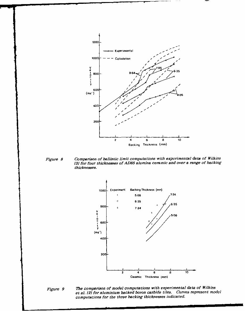
Comparison with the full range of data provided by Wilkins [1) for four ceramicthicknesses did not, however, fit this picture exactly. To fit Wilkins data it was necessaryto increase the ceramic effective strength with thickness such that for thick plates theappropriate strength is close to the hardness. The fit to Wilkins [1 data using hardness asthe effective ceramic strength is shown in figure 8. It is best described as a reasonable fitto the data. Rather than curve fit exactly to empirical data by playing with strengthparameters, it was decided to use hardness throughout as the strength measure andconcentrate on the reliability of the computational approach and what it illustrates in thephysics of perforation of ceramic composite armours.
Several other measures of strength are possible. The most obvious is theHugoniot elastic limit, however this was not used as it is difficult and expensive to generatethe data, values are tabulated for only some ceramics of interest and in any case the valuesare similar to the strength levels in hardness tests. The conflict of the above approachwith the glass data of Pavel et al. 1151 as shown in figure 3 is at this stage attributed to thevery low fracture toughness of glass compared with the typical armour ceramics, whichwould allow glass to fragment easily producing stress relief. Ceramic and glass are thenconsidered separate situations to be modelled.
5. COMPARISON WITH EMPIRICAL DATA
The value of the model in terms of analysing and describing the mechanisms involved inperforation of ceramic composite targets is best appreciated by comparing computationswith existing experimental data. Such a process also allows the limitations of inbuiltassumptions to be tested. Comparison is made with data of several types from severalsources. In all cases ceramic strength and material stress/strain data was gleaned from thebest sources available, however, in general, whilst it may be for the same material type andcondition as used in the experiments, it should best be described as typical.
The fit of computations to the results of Mayseless et al. [41 in figure 7(a) couldbe considered reasonable. For the calculations on the Berkeley experiments there was noerosion of the ceramic and variations in ceramic strength will not improve the agreement.For all these computations the projectile erosion was part of the output and this iscompared with the experimental curve of Mayseless et al. 141 for projectile erosion infigure 7(b). The form is correct, however there is an underestimate of about two or threemillimetres in the amount of erosion. As the model is for a flat ended penetrator, and theexperimental work involved penetrators with a pointed nose several millimetres in lengthwhich would be readily broken, the difference between the experiment and the model iseasily understood. In fact at very low velocities the experimental data shows a step jumpin the magnitude of erosion.
The influence of ceramic erosion on predictions of the model is illustrated in thecomputations of figure 8. The reason for the two distinct slopes in the calculated curves is
14
the reduction in the effective loaded volume of ceramic and backing as represented infigure 5(c); without this change in volume the graphs would continue at the initial slope. Itis noted that for each ceramic thickness the slope change in the calculated curves occursconsistently over a narrow velocity range which is determined by the ceramic strength. Incontrast to this Wilkins' experimental data shows a discontinuity consistently occurring atapproximately the same backing thickness for each of the ceramic thicknesses. The mostplausible explanation of this difference is that a lower stiffness in thinner ceramic tilesallows easier bending to a strain at which fracture is initiated, reducing the effectivestrength of thinner tiles. The overall agreement between the calculations and theexperiment is seen to be good when the pairs of experimental and calculated curves areexamined individually. As indicated above, one can improve the fit by selectingappropriate ceramic strength figures which increase with tile thickness, however this thenbecomes a curve fitting exercise with less meaning in the results. Certainly a validapproach would be to use ballistic testing and the model together under conditions whereceramic erosion is expected, in order to gauge the effective ceramic strength for thoseimpact conditions. Rosenberg and Yeshurun [61 pointed out that, contrary to theirexpectations, some of Wilkins' data shows no correlation between ballistic efficiency andcompressive strength. From the present model this is in fact seen to be quite reasonable asWilkins' data generally refers to conditions with backings which are thin enough thatceramic erosion, and hence strength, is of no significance. Under such conditions theeffects of the ceramic are to induce erosion of the softer penetrator, and in the mass ofceramic cone material which must be accelerated. The experiments of Rosenberg andYeshurun [61 are on semi-infinite backings. As seen in figure 8, even for the relatively lowstrength AD-85 alumina, it is with the thicker backing where erosion of the ceramic occursthat the ceramic strength limits the rate of increase in performance with backing thickness.
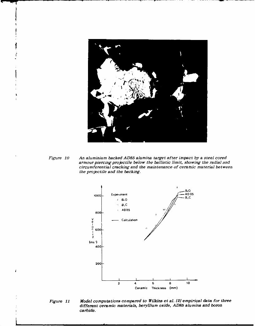
The effect of ceramic and backing thicknesses are again shown in figure 9 forthe data of Wilkins et al. [21 using aluminium backed boron carbide tiles. The calculationsgive the correct ordering with ceramic and backing thickness and are as close to theexperimental data as could be expected given the approximations in the model. In this casethe model predicts no ceramic yielding, and hence no erosion, of the tiles. This is notmeant to imply that the ceramic does not fragment, just that in the time frame of theballistic event it is not eroded from its position ahead of the projectile. That ceramicfragmentation and erosion are not necessarily the same is shown by figure 10 which showsdebris from the impact of an armour piercing round on an AD85 alumina target. Despitesignificant fragmentation the result of inertia and a resilient adhesive bond is to keep alarge part of the fracture conoid in place.
Results for three different ceramics are shown in figure 11. The slightdifferences predicted by the model result from density differences which determine themass of ceramic to be accelerated, and by the yielding of the AD85 alumina leading to aslope change at the highest velocities. The predictions of ballistic limits are extremelygood. On this scale the model orders the ceramics incorrectly compared with theexperiments, however if areal density was used rather than tile thickness to plot the data,the experimental and model results would separate into three distinct sets in the correctorder, because of large density differences between the three materials, i.e. on thethickness scale that Wilkins et al. 121 used to plot the data the model is not sensitive to thedifferences.
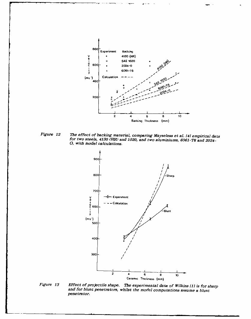
The formulation of the present model uses stress/strain behaviour suitable for ametallic backing, hence some composite materials are presently excluded fromconsideration. However, Mayseless et al. [41 show data for a range of backing materialsincluding several metals allowing the effect of backing material to be examined for somecases as in figure 12. This comparison shows the calculated magnitude and ordering ofperformance using the model to be correct, however for these results the modelconsistently underestimates the ballistic limits.
15

Wilkins (11 also presented a comparison of the performance of sharp and bluntpenetrators against AD85 alumina. The present model is for blunt penetrators and itsballistic limit predictions are compared with Wilkins' [1) data in figure 13. Unfortunatelythe computations fit the sharp penetrator data better. This comparison, whilst emphasisingthe effect of nose shape, highlights the approximate nature of the present approach.
The model treatment for the situation of a thick backing can be compared withdata of Bless et al. [28] who backed alumina tiles with semi-infinite aluminium blocks. Theexperimental data comprise the depth of penetration into a semi-infinite block, X,compared with the depth when the block is covered with a ceramic tile, R, as presented inTable 1, where the ceramic tile thickness is C. Computations of penetration into the semi-infinite block were made with a deep penetration model 126, 271 using the initial impactconditions to calculate X. For the case with the ceramic tile the program ECS was usedto treat the ceramic penetration and the output from these calculations used as input forthe same deep penetration model to calculate R. In a small number of cases in which asharp, hard penetrator was involved, a ductile hole formation model was more appropriatelyused for the calculations into a semi-infinite aluminium block. In the majority of casesTable 1 shows reasonable agreement. In most of those where agreement is poor, theimpact velocity was far in excess of that where any of the models are expected to work(i.e. > 1.5 km s-l). In a couple of cases where computational agreement was obtained,where the impact velocity was beyond the range of the models, it is considered acoincidence in the present instance, and these cases are not highlighted in Table 1 aseffective computations. At least in one case (Shot 4-452) Bless et al. [281 indicate thattheir "experimental" depth of penetration is only "estimated".
In making the above calculations with the program ECS for the thick backingproblem it was noted that ceramic erosion occurred whilst the penetrator was above somecritical velocity depending on the ceramic strength. Below this velocity only thepenetrator was eroded and decelerated with the calculations stopping when the penetratorwas reduced to zero mass or velocity. In those cases where the impact velocity was justabove the value for erosion of the ceramic, the deceleration during the interaction wassufficient to reduce the projectile velocity below the critical value and ceramic erosionstopped before the ceramic in front of the projectile was completely removed. In all caseswhere the ceramic was not perforated Table 1 shows zero residual perforation. In practicea few millimetres of deformation is always observed due to fracture of the ceramic andimpact of the residual debris.
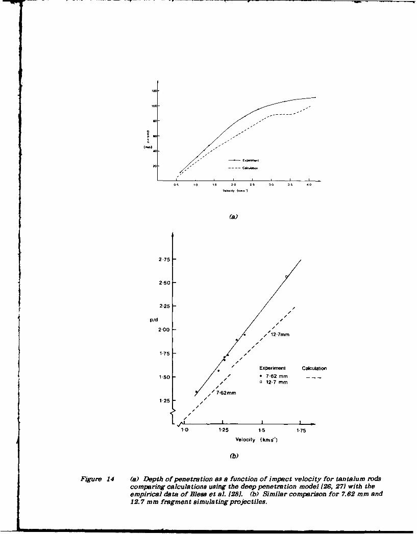
The effectiveness of the deep penetration model for doing the part of thecalculation involving penetration into the metal backing was checked using comparisonswith the calibration data of Bless et al. [281 in figures 14(a) and 14(b) for tantalum rods andfragment simulating projectiles respectively. The comparisons of Table 1 and Fig. 14indicate that the approach used to treat targets with thick backings may give goodestimates of behaviour up to impact velocities of the order of 1.5 km s -I .
A final comparison is with data of Rosenberg and Yeshurun [5, 61 who define aballistic efficiency (7) of a ceramic as
Pp*PAlPAl
= (15)p c h c
where h* is the minimum ceramic thickness required to preventc penetration into a thick aluminium backing,
16
PAl is the penetration depth of the projectile intobare aluminium, and
pAl and p_ are the densities of aluminium and ceramicrespe tively.
The ballistic efficiency is then obtained from the slope of a graph of pAlhAl versuspchc and the results of Rosenberg and Yeshurun 15, 61 are represented as a continuousstraight line in figure 15 for AD85 alumina.
The points of intercept on the ordinate and abscissa for defining the line ofslope rl may be found from the model solutions using the following procedure. As thepenetrator is sharp and hard the depth of penetration into a semi-infinite target isestimated using the ductile hole formation model [18, 23], and as figure 15 shows this pointis where the Rosenberg and Yeshurun line for AD85 meets the ordinate. The ceramicpenetration model for the thick backing case, program ECS, is then combined with the deeppenetration model [26, 271 to calculate a curve for increasing ceramic thicknesses and thusat a range of pc hc values, till the curve crosses the abscissa. The crossing points on theordinate and abscbissa are joined with a straight line to obtain the line equivalent to that ofRosenberg and Yeshurun [5, 6]. This is shown as a dashed line in figure 15 for an assumedAD85 alumina strength of 5.6 GPa. This is smaller than the 8.8 GPa used in earliercalculations because under the impact conditions of velocity, penetrator and ceiamicstrengths, the higher value of ceramic strength would not have allowed any penetration withthe present model. A lower value of strength was therefore chosen which allowed somelevel of agreement to be achieved.
It is immediately noticed in figure 15 that the blunt penetrator model givesmuch lower penetration depth than the ductile hole formation model, where no ceramic tileis present, and this accounts for a large part of the apparent effectiveness of theceramic. In fact the graphs indicate the prime influence of the ceramic is in destroyingthe projectile point, reducing substantially its penetrating capability, and represented bythe discrepancy of the ductile hole formation and deep penetration models on theordinate. It is also noted that the calculations with ceramic tiles indicate thatexperimental data points should only fall on a straight line of slope r7 by coincidence if thedata is determined for thick ceramic tiles giving low values of pAlhAl; in fact this iswhere the experimental data of Rosenberg and Yeshurun [5, 6] is clustered. Finally forsome of the harder ceramics tested by Rosenberg and Yeshurun [5, 61, a 12.7 mm steelcored projectile at the velocities of their experiments would not cause ceramic erosion,hence preventing impact on the aluminium backing according to the present model. Inpractice the experimental arrangement used without any side constraint allows easyfragmentation and ejection failure of the tile and hence easier perforation by projectilefragments. This phenomenon would not occur in a properly restrained armourconfiguration. At this stage therefore it is still questionable whether a ceramic strengthparameter suitable for one configuration is necessarily also suitable for all other ceramicarmour configurations. The three effects presented here, destruction of the projectile noseprofile, real ceramic erosion effects, and unrestrained fragmentation and ejection of thetile are not linearly related to ceramic thickness. Thus the experimental method ofdetermining the ballistic efficiency, ri, may be treated as a useful technique for comparingperformance, with caution in attributing a single physical meaning to the results. Thiscomparison also raises the question of how to treat ceramic attrition, accounting for boththe erosion effects at high velocity and the fragmentation at low velocity, in a model of thepresent form.
17

6. DISCUSSION
There is no pretence that the models presented in the present work are to be considered anexact simulation of the physics of impact, however the straightforward descriptions of thephysics which they embody leads to reliable and relatively simple algorithms which givereasonable quantitative estimates of ceramic performance. In addition the predictions ofchanges with variations in ceramic and backing material type and thickness, and projectilematerial and dimensions are such that the models should be useful for parametric studiesand for guiding experiments and design. The concepts as presented in figures 4, 5 and 6therefore probably embody most of the principal features of the impact event. Moreaccurate physical modelling with increased complexity of the algorithms can be expected tolead to better predictions of performance. Approximations on aspects of both the physicsand the material properties are so gross that the degree of concurrence with experimentover such a wide range could be considered truly remarkable.
A major omission is the neglect of radial inertia. Not only is the momentum oferoded projectile material destroyed, but also it must be ejected laterally at somevelocity. The treatment used by Johnson [19] for high rate compression was not easilyadopted in the present instance as the radial inertia force becomes excessive as thethickness of the deforming zone becomes small which, with the present model, is dependenton the time step. The most profitable approach would appear to be to consider the erodedprojectile material as having a momentum change associated with a velocity changefrom 10 to some radial ejection velocity (1,, rather than by having its momentum destroyedas in tie conventional modified Bernoulli dyproach [161. At present the extra variablewould seem to make the equations insoluble. This would however maintain the same logicas considering an increase in momentum associated with the velocity (I picked up by theeroded ceramic, and it may be possible to relate Q and in some wa9.
In treating the backing deformation which is largely a dishing or bulge formationproblem, the location of the hinge is a convenient conjecture. There is no doubt that inpractice both significant elastic contributions to deflection and expansion of the hingeradially influence both the energy absorption and the effective observed ductility of thebacking material. The simple linear thickness variation and the choice of instabilitycriterion fortunately give overall deflections which are in accord with experience.
The deflection of the backing makes easier the radial and circumferentialcracking in the ceramic. When bending occurs the resultant lack of support due to thebending allows ejection of fragmented ceramic from the back, and in addition ejection ofceramic on the impact side is resisted less than the extrusion of material when thepenetrator gets deeper into the ceramic tile. For this problem there is almost a completelack of knowledge on material continuity and consolidation at any time. The wholequestion of how ceramic fragmentation influences effective strength is unresolved. Theuse of hardness in the present instance as a guide to strength is seen to be an effectivestarting point.
Projectile shape is limited to the assumption of a flat ended cylinder. This isseen to highlight how approximate the model is in Fig. 13 as the model does not have thesensitivity to at least plot nearer to experimental data for the blunt projectiles. Thatceramics quickly negate, by fracture, the influence of a sharp nose is highlighted by thediscussion of figure 15. Questions on projectile shape will not be resolved by onedimensional models such as these and must rely on experiment and two and threedimensional simulations for detailed examination.
Despite the above difficulties, and the questions of ceramic effective strengthin particular, the comparisons in this study show the models and associated computerprograms, CEP and ECS, to be effective tools for the study of ceramic armour behaviour.
18

The programs should not be used for the prediction of performance, rather as aguide in understanding the interactions. Thus the program for thick backings, ECS, may, bysimulating experiments, enable studies of the effective pressure at which erosion occurs andhow this is influenced by material and confinement.
7. CONCLUSIONS
This work has presented two models for the perforation of ceramic composite armours, onefor the perforation of targets with thin backing plates, which deform by bending away underthe influence of the ceramic fracture conoid to fail by a biaxial tensile fracture, and theother for targets with a thick backing, where the backing remains undeformed whilst theceramic erodes and is then perforated by the residual projectile fragment. The details ofceramic fragmentation are avoided in the model which treats the dynamics of movement ofblocks of material with macroscopic failure criteria for both ceramic and backing.Comparisons of computations with empirical data demonstrate a good correlation, and themodel can be used for parametric studies, to assist with the analysis of experimental dataand for design. Ceramic hardness is used as a strength parameter, however theconsideration of ceramic strength appropriate to ballistic impact is considered a majoraspect for further investigation.
8. REFERENCES
1. Wilkins, M.L. (1978). Mechanics of penetration and perforation. InternationalJournal of Engineering Science. 16, 793-807.
2. Wilkins, M.L., Cline, C.F. and Honodel, C.A. (1969). Fourth progress report of lightarmour program (Report UCRL-50694). Livermore: Lawrence RadiationLaboratory, University of California.
3. Wilkins, M.L. (1980). Computer simulation of penetration phenomenon. InR.C. Laible (Ed) Ballistic materials and penetration mechanics Elsevier Sci. Pub.Co., 225-252.
4. Mayseless, M., Goldsmith, W., Virostek, S.P. and Finnegan, S.A. (1987). Impact onceramic targets. Journal of Applied Mechanics, 54, 373-378.
5. Rosenberg, Z. and Yeshurun, Y. (1987). An empirical relation between the ballisticefficiency of ceramic tiles and their effective compressive strength. Proceedings10th International Symposium on Ballistics, ADPA, San Diego, California.
6. Rosenberg, Z. and Yeshurun, Y. (1988). The relation between ballistic efficiency andcompressive strength of ceramic tiles. International Journal of ImpactEngineering, 7, 357-362.
19

7. Nicol, B., Pattie, S.D., O'Donnell, R.G. and Woodward, R.L. (1988). Fracture ofceramics in composite armours. In Fracture Mechanics in Engineering Practice,Conference of Australian Fracture Group Melbourne University.
8. Frank, F.C. and Lawn, B.R. (1967). On the theory of hertzian fracture. Proceedingsof the Royal Society A299, 291-306.
9. Knight, C.G., Swain, M.V. and Chaudhri, M.M. (1977). Impact of small steel sphereson glass surfaces. Journal of Materials Science, 12, 1573-1585.
10. Lawn, B.R. and Swain, M.V. (1975). Microfracture beneath point indentations inbrittle solids. Journal of Materials Science 10, 113-122.
11. Lawn, B. and Wilshaw, R. (1975). Review indentation fracture: Principles andapplications. Journal of Materials Science, 10, 1049-1081.
12. Ostojic, P. and McPherson, R. (1987). A review of indentation fracture theory: Itsdevelopment, principles and limitations. International Journal of Fracture 33,297-312.
13. Woodward, R.L. (1988). Some aspects of cone crack propagation in finite thicknessglass plates. In The Material Wealth of the Nation, Proceedings of Institute ofMetals and Materials Australasia Bicentennial Conference, Sydney, Australia, 1,111-118.
14. Hornemann, U., Rothenhausler, H., Senf, H., Kalthoff, J.F. and Winkler, S. (1984).Experimental investigation of wave and fracture propagation in glass slabs loadedby steel cylinders at high impact velocities. In J. Harding (Ed.) MechanicalProperties at High Rates of Strain, Institute of Physics Conference Series No. 70,Institute of Physics, Bristol & London, 291-298.
15. Pavel, W., Raatschen, H.-J., Schwarz, R., Senf, H. and Rothenhausler, H. (1987).Experimental and numerical investigations of the failure behavior of glass targetsunder impact loading by rigid projectiles. Proceedings of 10th InternationalSymposium on Ballistics ADPA, San Diego, California.
16. Tate, A. (1967). A theory for the deceleration of long rods after impact. Journal ofthe Mechanical and Physics of Solids 15, 387-399.
17. Tabor, D. (1951). The hardness of metals. Oxford: Clarendon Press.
18. Woodward, R.L. (1978). The penetration of metal targets by conical projectiles.International Journal of Mechanical Science, 20, 349-459.
19. Johnson, W. (1972). Impact strength of materials. p 152, Arnold.
20. Woodward, R.L., O'Donnell, R.G., Baxter, B.J., Nicol, B. and Pattie, S.D. (1989).Energy absorption in the failure of ceramic composite armours. To be publishedin Materials Forum.
21. Johnson, W. Ibid. p. 194.
22. Johnson, W. and Mellor, P.B. (1962). Plasticity for mechanical engineers.Von Nostrand, p 187.
23. Taylor, G.I. (1948). The formation and enlargement of a circular hole in a thin plasticsheet. Quarterly Journal of Mechanical and Applied Mathematics 1, 103-124.
20
24. Woodward, R.L. and de Morton, M.E. (1976). Penetration of targets by flat-endedprojectiles. International Journal of Mechanical Science, 18, 119-127.
25. Woodward, R.L. and Crouch, I.G. (1988). Analysis of the perforation of monolithicand simple laminate aluminium targets as a test of analytical deformation models(MRL Report MRL-R-1111). Maribyrnong, Vic.: Materials Research Laboratory.
26. Woodward, R.L. (1982). Penetration of semi-infinite metal targets by deformingprojectiles. International Journal of Mechanical Science. 24, 73-87.
27. Woodward, R.L. (1981). Modelling penetration by slender high kinetic energyprojectiles (MRL Report MRL-R-811). Maribyrnong, Vic.: Materials ResearchLaboratory.
28. Bless, S.J., Rosenberg, Z. and Yoon, B. (1987). Hypervelocity penetration of ceramics.International Journal of Impact Engineering 5, 165-171.
21
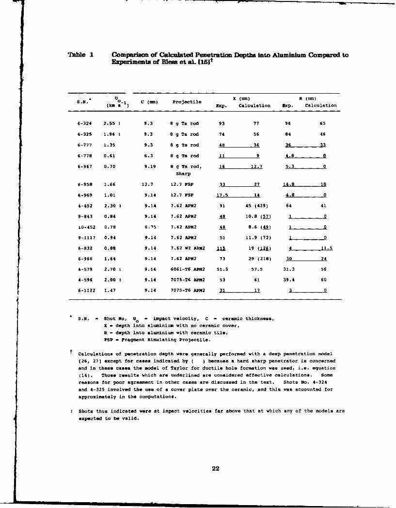
Table 1 Comparison of Calculated Penetration Depths into Aluminium Compared toExperiments of Bless et aL [151t
S.N. U - C (umm) Projectile X (mm) R (Im)
(km a ) Exp. Calculation Exp. Calculation
4-324 2.55 ! 9.3 8 g Ta rod 93 77 96 65
4-325 1.96 ! 9.3 8 g Ta rod 74 56 84 46
6-777 1.35 9.3 8 g Ta rod 48 36 36 33
6-778 0.61 6.3 8 g Ta rod 11 9 4.8 0
6-967 0.70 9.19 8 g Ta rod, 16 12.7 5.3 0
Sharp
6-958 1.66 12.7 12.7 FSP 33 27 14.8 18
6-969 1.01 9.14 12.7 FSP 17.5 14 4.8 0
4-452 2.30 I 9.14 7.62 APH2 91 45 (429) 64 41
9-843 0.84 9.14 7.62 AP2 48 10.8 (57) 1 0
10-452 0.78 6.15 7.62 AP42 48 8.6 (A9) 1 0
9-1117 0.94 9.14 7.62 APM2 51 11.9 (72) 1 0
6-832 0.88 9.14 7.62 W2 APM2 115 19 (126) 4 11.5
6-966 1.64 9.14 7.62 AP2 73 29 (218) 30 24
4-579 2.70 1 9.14 6061-T6 APR2 51.5 57.5 31.3 56
4-596 2.80 ! 9.14 7075-T6 AP2 53 61 39.4 60
6-1122 1.47 9.14 7075-T6 AP2 31 17 3 0
S.N. - Shot No, U - impact velocity, C - ceramic thickness,o
R - depth into aluminium with no ceramic cover,R - depth into aluminium with ceramic tile,
FSP - Fragment Simulating Projectile.
Calculations of penetration depth were generally performed with a deep penetration model
(26, 27] except for cases indicated by ( ) because a hard sharp penetrator is concerned
and in these cases the model of Taylor for ductile hole formation was used, i.e. equation
(14). Those results which are underlined are considered effective calculations. Some
reasons for poor agreement in other cases are discussed in the text. Shots No. 4-324
and 4-325 involved the use of a cover plate over the ceramic, and this was accounted for
approximately in the computations.
Shots thus indicated were at impact velocities far above that at which any of the models are
expected to be valid.
22

APPENDIX 1
CEP - COMPUTER PROGRAM FOR THIN BACKING CERAMICCOMPOSITE TARGETS
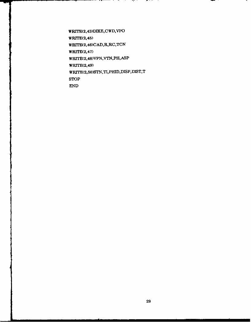
The computer program CEP solves the problem of perforation of targets consisting of aceramic tile backed by a thin ductile metal backing material. The program calls on aninput file CIP.DAT and it increments projectile velocity from the initial value until acondition is found at which the ceramic is just perforated. At this velocity the programstops and creates an output file, COP.DAT, containing a number of the more usefulcalculated parameters. A typical input is listed at Table A1.1 and a typical output atTable A1.2, followed by a listing of the program.
I-able AIL Typical Input CIP.DAT
Parameter Symbol in Program Units Typical Value
Initial Velocity Estimate VPO ms71 400.
Penetrator Yield Strength YP MPa 2300.
Penetrator Density ROP g cm- 3 7.85
Penetrator Mass ASP g 30.
Penetrator Diameter DP mm 12.7Penetrator Height HP mm 30.17
Ceramic Thickness TG mm 6.35
Ceramic Density ROC gcm- 3 3.4
Ceramic Vickers Hardness HARC GPa 8.8
Backing Thickness TB mm 14.
Backing Density ROB gcm- 3 2.7
Backing Strength, A eq.(8) AB MPa 280.
Backing Strength, B eq.(8) BB MPa 268.
Backing Work HardeningExponent, n eq.(8) ENB - .513
23
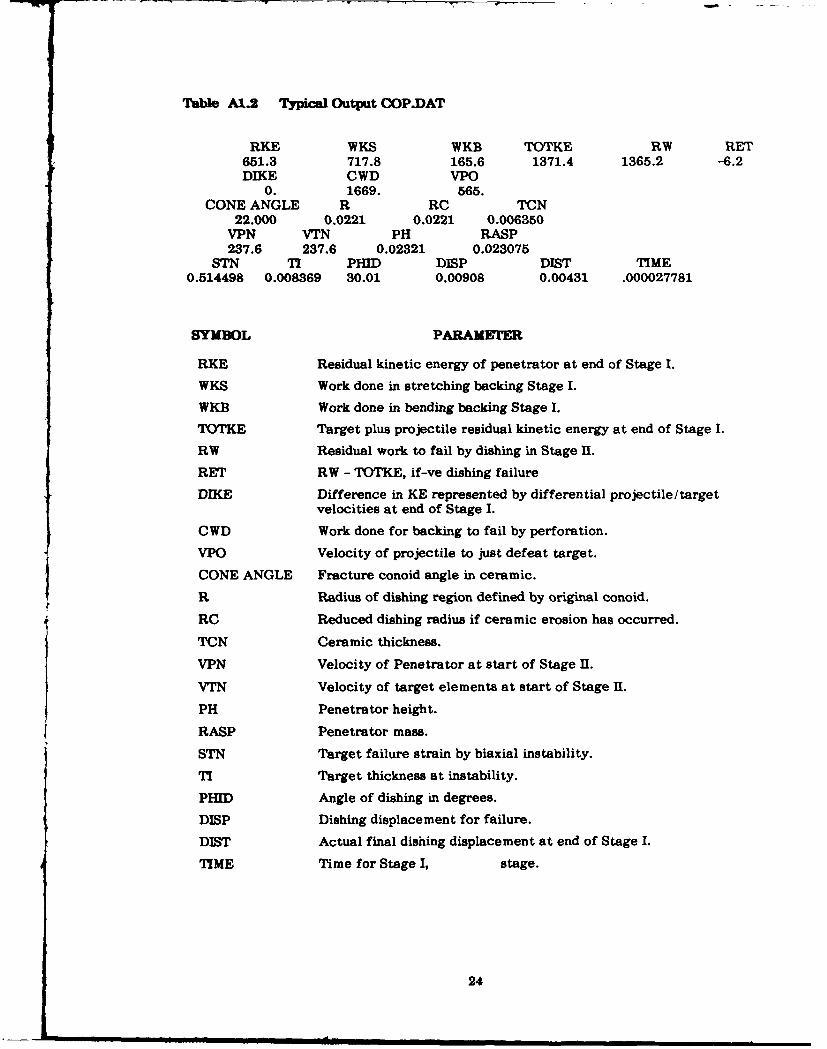
Table A1.2 Typical Output COP.DAT
RKE WKS WKB TOTKE RW RET651.3 717.8 165.6 1371.4 1365.2 -6.2DIKE CWD VPO
0. 1669. 565.CONE ANGLE R RC TCN
22.000 0.0221 0.0221 0.006350VPN VTN PH RASP237.6 237.6 0.02321 0.023075
STN TI PHID DISP DIST TIME0.514498 0.008369 30.01 0.00908 0.00431 .000027781
SYMBOL PARAMETER
RKE Residual kinetic energy of penetrator at end of Stage I.
WKS Work done in stretching backing Stage I.
WKB Work done in bending backing Stage I.
TOTKE Target plus projectile residual kinetic energy at end of Stage I.
RW Residual work to fail by dishing in Stage 1.
RET RW - TOTKE, if-ve dishing failure
DIKE Difference in KE represented by differential projectile/targetvelocities at end of Stage I.
CWD Work done for backing to fail by perforation.
VPO Velocity of projectile to just defeat target.
CONE ANGLE Fracture conoid angle in ceramic.
R Radius of dishing region defined by original conoid.
RC Reduced dishing radius if ceramic erosion has occurred.
TCN Ceramic thickness.
VPN Velocity of Penetrator at start of Stage H.
VTN Velocity of target elements at start of Stage I.
PH Penetrator height.
RASP Penetrator mass.
STN Target failure strain by biaxial instability.
TI Target thickness at instability.
PHID Angle of dishing in degrees.
DISP Dishing displacement for failure.
DIST Actual final dishing displacement at end of Stage I.
TIME Time for Stage I, stage.
24

C CEP.FOR
C PROGRAM TO CALCULATE BALLISTIC LIMIT AND ENERGY CONSUMPTION
C IN SMALL CALIBRE AP DEFEAT OF CERAMIC FACED COMPOSITES
C WRITEN BY RAYMOND L WOODWARD, MATERIALS RESEARCH
C LABORATORY, MARIBYRNONG,1989
C
OPEN(UNrT=1 ,FILE--'CIEP.DAr,STATUS='OLD')
OPEN(UNrr=2,FILE='COP.DA,STATUS='NEW')
21 FORMAT(F8.1/F8.1/F1O.4/Fl0.4/FlO.4/Fl0.3/Fl0.4/
lF8.31F6.2/FI0.31F8.4/F10.1 fF10.1 fF8.3)
41 FORMAT(T1 1,'RKET24,'WKS-T38,'WKBT48,'TOTKE-T65,'RW-r75,'RE-r)
42 FORMAT(4X,F1O.1,4X,F1O.1,4X,F1O.1,2X,F1O.1,4X,F8.1,4X,F6.1)
43 FORM AT(4X,F1O.0,4X,F10.0,4X,F1O.0)
44 FORM AT(Tl0,'DIKE'T25,'C WD-T38,'VPO')
45 FORMAT(T5,'CONE ANGLE'T23,'R'T35,'RC'T47,'TCN')
46 FORM AIX8X, F6.3,4X, F8.4,4X, F8.4,4X, F8.6)
47 FOR MAT(T8,'VPN'T18,'VTN'T3O,'PH'T42,'RASP')
48 FOR MAT(4X,F8.1,2X, F8.1,4X, F8.5,4X,FI0.6)
49 FORM AT(T6,'STN'T16TI'T24 ,'PID'T36,'DISP'T50 ,'DIST'T63,'TIME')
50 FORM AT(2X,F8.6,2X,F8.6,2X,F6.2,6X,F8.5,6X,F8.5,4X,F10.9)
READ(1 ,21)VPO,YP,ROP,ASP,DP,HP,TC,ROC,HARC,TB,ROB,AB,BB,ENB
YP=YP*1000000.
ROP=ROP* 1000.
ASPO=ASPs .001
DP=DP* .001
HPO=HP* .001
TC=TC* .001
ROC=ROCS 1000.
HARC=HARC* 1000000000.
FC=.7854*HARC*(DP* *2)
TB=TB* .001
ROB=ROB* 1000.
AB=-AB* 1000000.
BB=BB* 1000000.
ASF=ASP /HP
DT= .0000000 1
25

C CALCULATE BACKING INSTABILITY STRAIN
t C STNO=-0.359FNO=11 .BB*(STNO* *(ENB+1))-(8*ENB+4)*BB*(STNO* *ENB)1+(11*AB*STNO)-4*AB
DO 33 N=1,10000
STN1=STNO+.001I FN1=11*BB*(STN1* *(ENB+1))-(8*ENB+4)*BB*(STh1 **ENB)
2+(11*AB*STN1)-4*AB
IF(FNI.EQ.0)GO TO 31
SGN=FN1 /FNO
IF(SGN.LT.0)GO TO 30STN0=STN1
FNO=FN1
33 CONTINUE
30 STN=-(STNO+STN1)*0.5GO TO 32
31 STN=STN1
32 CONTINUE
C
C BEGIN STEPPING VELOCITY,TILL V50 FOUND
C
DO 101 K=1,500
vP=VPo
VPO=VPO+5.
T=-O
PKE=0.5s ASP*(VP. *2)
TCN=TC
HP=HPO,
ASP=ASPO
C
C CONE ANGLE/RADIUS OF DISHED REGION/MASS CONE/CONSTANTS
C
CA-.383972
CAD=CA*57.296
R=<TC /TAN(CA))+(DP/2)
ASCB-3.14159*((TC*ROC 12)+(TB*ROB))*(R* *2)13
F1=YP*0.7854*(DP* *2)
26

FCF=DT*(FC-Fl)
F2=F1+(VP**2)*ASF
C
C TICKNESS AT INSTABILITY /BEND ANGLE
C
TI=TB /EXP(STN)
PHI=ACOS( .66666667+TI/(3*TB))
PBflD=PIl* 57.296
DLSPO=(R-DP/2)*TAN(PHI)
YSB=AB+BB*(STN* *ENB)/(ENB+l)
Cl=ROC/ROP
A=-C1 /(ASF*DT)
C3=ASF*DT* Cl
C
C TARGET ACCELERATION /PROJ. EROSION AND DECELERATION
C
DIST=0
VT=0
F3=2.0944*YSB*(TB* *2)
D072 1=1,50000
DISP=DISPO
T=T+DT
DVP=Fl*DT/ASP
IF(F2.GT.FC)GO TO 14
DVT=(F2-F3)* DT/ASCB
GO TO 15
14 DVT=(FC-F3)*DT/ASCB
15 VPN=VP-DVP
VTN=VT+DVT
DLST=DIST+(VTN+VT)*DT /2
IF(F2.LT.FC)GO TO 18
B=-(1+2*C1)*(VP+VPN)12+(VT+VTN)*Cl /2
C=-C3*(VP-~VT±VPN-VTN)*(VP+VPN) /4-FCF
DAS=-BI(2.- A)-(SQRT(B**2--4*A*C))I(2*A)
GO TO 19
18 DAS=-(VPN+VP-VT-VTN)*D)T*ASF/2?
19 DTC=((VPN+VP)*DT/2)+DASIASF-(VT+VTN)*DT/2
TCN=TCN-DTC
27

RC--(TCN /TAN(CA))+DP/2
ASCB-1 .0473*((TCN*ROC /2)+(TE*ROB))*(RC* *2)
DISP=-(RC-DP/2)*TAN(PHD
91 ASP=ASP+DAS
F3--(2.0944*(TB* *2)+3.14159*TB*DJ5T)*YSB
F2=Fl-DAS*VPN /DT
IF(TCN.LE.0)GO TO 88
IF(DIST.GE.DISP)GO TO 88
EF(VTN.GE.VPN)GO TO 88
VP=VPN
Vr=VTN
72 CONTINUE
88 CONTINUE
C
C CALC OF ENERGIES AND OUTPUT
C54 PH=ASP/ASF
DIKE=-0.5*ASP*((VPN-VTN)* *2)
CWD=1 .5708*(DP* *2)*TB*(AB+BB*(STN* *ENB))
RKE=0.5*ASP*(VPN* *2)
WKS=2.0944*(TB* *2)*DIST*YSB
WKB-1 .5707*TB*(DIST* *2)*YSB
TKE--3.14159*(RC* *4)*(VTN**2)*((TCN*ROC 120)+(TB*ROBI12))
1 /((RC-DP/2)**2)
TOTKE--RKE+TKE
RW=-3.14159*TB*YSB*(.6667*TB*(DISP-DIST)+0.5*((DISP* *2)
1-(DIST* *2)))
RET=RW-TOTKE
C FAILURE BY DISHING IN STAGE 2
I1F(RET.LT.0)GO TO 102
C FAILURE BY PERFORATION
][F(DIKE.GT.CWD)GO TO 102
C FAILURE BY DISHING IN STAGE 1
IF(DIST.GE.DISP)GO TO 102
101 CONTINUE
102 WRITE(2,41)
WR1TE2,42)RKE, WKS, WKB,TOTKE,RW,RET
WRITE(2,44)
28
WRrrE(2,43)DIKE,CWD,VPO
WRrrE(2,45)
WR1TE(2,46)CAD,R,RC,TCN
WRrrE(2, 47)
WRrTE(2,48)VPN,VTN,PH,ASP
WRrTE(2,49)
WRITE(2,50)STN,TI,PH[D,DISP,DIST,T
STOP
END
29
APPENDIX 2
ECS - PROGRAM FOR CERAMIC PERFORATION WHEN BACKEDBY A THICK PLATE
The computer program ECS solves the problem of perforation of a ceramic tile when it issupported by a very thick backing which shows negligible deflection until the ceramicblock is completely eroded. The program calls on the input file EIS.DAT and producesan output file EOS.DAT showing residual projectile mass and velocity after ceramicerosion. The latter data can then be fed into an appropriate model to examine theperforation of the backing. A typical input is listed at Table A2.1 and the correspondingtypical output at Table A2.2, followed by a listing of the program.
Table A2.1 Typical Input ElS.DAT
Parameter Symbol in Program Units Typical Value
Penetrator Velocity VP ms - 1 1200.
Penetrator Yield Stress YP MPa 2500.
Penetrator Density ROP g cm - 3 7.85
Penetrator Mass ASP g 23.1
Penetrator Diameter DP mm 10.8
Ceramic Thickness TC mm 6.
Ceramic Density ROC g cm- 3 3.4
Ceramic Vickers Hardness HARC GPa 8.8
30

Table A2.2 Typical Output EOS.DAT
0.00555 1190.0 0.02256 0.000001000.00511 1179.7 0.02203 0.000002000.00469 1169.2 0.02149 0.000003000.00428 1158.4 0.02095 0.000004000.00388 1147.3 0.02040 0.000005000.00350 1135.9 0.01986 0.000006000.00313 1124.2 0.01931 0.000007000.00278 1112.2 0.01876 0.000008000.00244 1099.8 0.01821 0.000009000.00212 1087.0 0.01765 0.000010000.00182 1073.9 0.01709 0.000011000.00154 1060.2 0.01652 0.000012000.00127 1046.1 0.01596 0.000013000.00103 1031.5 0.01538 0.000014000.00081 1016.3 0.01480 0.000015000.00062 1000.6 0.01422 0.000016000.00044 984.1 0.01363 0.000017000.00030 966.9 0.01303 0.000018000.00019 948.9 0.01242 0.000019000.00010 930.0 0.01181 0.000020000.00006 910.1 0.01118 0.000021000.00005 889.0 0.01054 0.000022000.00005 866.6 0.00991 0.000023000.00005 842.8 0.00929 0.000024000.00005 817.3 0.00870 0.000025000.00005 790.0 0.00812 0.000026000.00005 760.8 0.00756 0.000027000.00005 729.4 0.00702 0.000028000.00005 695.5 0.00651 0.000029000.00005 659.0 0.00602 0.000030000.00005 619.4 0.00556 0.000031000.00005 576.6 0.00513 0.000032000.00005 530.2 0.00474 0.000033000.00005 479.8 0.00437 0.000034000.00005 425.4 0.00405 0.000035000.00005 366.6 0.00376 0.000036000.00005 303.7 0.00352 0.000037000.00005 236.7 0.00333 0.000038000.00005 166.2 0.00318 0.000039000.00005 93.0 0.00309 0.000040000.00005 18.3 0.00305 0.00004100TCN VPN ASP T
0.00005 -0.5 0.00305 0.00004125
Symbol Parameter
TCN Ceramic Thickness (m)VPN Penetrator Velocity (ms - 1 )ASP Penetrator Mass (kg)T Time (S)
In each case the value under the symbol is the final value. In the above exampleceramic erosion had stopped after 2 microseconds because the penetrator velocity wasreduced below the value at which the ceramic strength was exceeded. Projectile erosioncontinued till the penetrator velocity was reduced to zero after 42.5 microseconds.
31
C ECSo PROGRAM FOR CALCULATING CERAMIC/PROJ. EROSION WHEN BONDEDC TO A SEMI-INFINITE PLATEC WRITEN BY RAYMOND L WOODWARD, MATERIALS RESEARCHC LABORATORY, MARIBYRNONG,1989
OPEN(UNrr=l,FELE-'EIS.DAT',STATUS='OLD')OPEN(UNrr=2,FILE=-'EOS.DA7r,STATUS='NEW')
21 FORMAT(F8.1 fF8.1 /F1O.4/F1O.4/F1O.4/F1O.4/F8.3/F6.2)47 FORMAT(T8,-rCNI18,'VPN-T30,'ASP-T42,-T)48 FORMAT(4X,F8.5,2X,F8.1,4X,F9.5,4X,F1O.8)
READ(1,21)VP,YP,ROP,ASP,DP,TC,ROC,HARCI YP=YP* 1000000.ROP=ROP*1000.ASP=ASP*.001DP=DP* .001TC=TC*.001TCN=TCROC=ROC*1000.HARC=HARC*1000000000.YC=HARC /1.0ASF=.7854*ROP*(DP* *2)F1=YP* .7854*(DP*2)T=0oDT=.00000001F3=YC* .7854*(DP**2)FCF=DT*(F3-Fl)C1=ROC/ROPA=0O-C1 /(PSF*DT)C3=ASF*DT*ClF2=Fl-4(VP* *2)*ASFDO 72 1=1,50000T=T+DTDVP=Fl*DT/ASPVPN=VP-DVPIF(F2.LT.F3)GO TO 18B=0O-(VPN+VP)*(1+2*C1)/2C=0O-C3*((VPN+VP)* *2) /4-FOFDAs-0-B/(2*A)-(SQRT(B* .2-4*A*C)) I(2*A)GO TO 19
18 DAS=-ASF*(VPN+VP)*DT/219 DTC=-((VPN+VP)*DT/2)+DAS/ASF
TCN=TCN-DTCASP=ASP+DASVP=VPNF2=F1-DAS*VPN/DTDO 83 N-1,500INC=N*100IFa-INC)84,79,83
83 CONTINUE79 WRrTE2,48)TCN,VPN,ASP,T84 IF(ASP.LE.0)GO TO 88
IF(VPN.LE.0)GO TO 88IF(TCN.LE.0)GO TO 88
72 CONTINUE88 WRITE(2,47)
WRrTE2,48)TCN,VPN,ASP,TSTODPEND
32

(a) (b) (C)
t .st 3.8 ps t 9.9 /is
AD-85
Al
(d) (e) f
t =14T as t 21.9ps t 27.0 Ps
Figure 1 Computer simulation of the early stages of perforation of an 8.6 mm ceramictile backed with 6.4 mm 6061-716 aluminium by a projectile impacting at858 rns. Th2e projectile erosion and format~ion of a fracture conoid in theceramic are evident. After Wilkins f3J.
Figur-e 2 Typical Vickers dia mond pyra mid inden ta tion in to a cera mic.

EXPERIMENTAL 0 EXPERIMENT (PAVEL etal)
1.0a THEORETICAL -PRESSURE= Y S
-PRESSJRE=2xY S
0.8-
'R VP 0.6-
0.4--
0.2--
0 40 80 120 160 200DSTO 4
GLASS THICKNESS (mm)
Figure 3 Calculations of the residual velocity/impact velocity ratio (V /Vf forperfora tion of glass targets by non -deforming projectiles. Piovalues ofpressure resisting penetration are used and the experimental points are from
Pavel et a). [151.

Ceramic
/ Hinge
Projectile / RealisticErosion
- " DuctileBacking Model
Ceramic/Erosion
UT
Cone VelocityCrack Profile
(b)(a)
M L F, F . FI
Projectile Target FT
(c)
Figure 4 Basic concepts of the interaction of a penetrator with a ceramic tile backedby a thin ductile plate. (a) Schematic of the eroding penetra tor, erodingceramic material, cone crack and positions of the hinges for dishing of thebacking. (b) Assumed velocity distribution in the ceramic and backingduring the first stage of acceleration. The more realistic distribution has aconstant velocity from the axis to the projectile diameter, however a slightlymodified distribution was used in the model for computational simplicity.(c) Lumped mass model, where the masses M and connecting forces F aredefined in the text. In a small time step masses AM and AM are erodedfrom the projectile and ceramic respectively. P c
DuctileInstabilityFailure
Fractured -r CConoid Ceramic
Debris
(a)
(b)
Original /Conoid
/ ReducedDimensions Reahstic {
Ceramic IuErosion
Ero -Velocity
Profile
(c) (d)
Figure 5 Second stage of perforation of the ceramic tile with a thin backing where (a)the projectile, ceramic and backing move as a unit till (b) a biaxial tensilefailure of the sheet occurs at an angle of bend e. (c) The assumedreduction in effective dimensions of the loaded conoid and backing plate as aresult of ceramic erosion. (d) Velocity distribution in the second stagewhere the more realistic distribution has a step near the reduced conoidouter diameter, but a simpler form is assumed for ease of computation.

Ceramic.,
Projectile Column ofErosion Eroding Ceramic
U~T =0
ThickBacking
(a)
Mp F, F
Projectile Target
(b)
Figure 6 Model concept for the thick backing problem where it is assumed that thebacking remains effectively stationary whilst the ceramic is eroded.(a) Schematic and (b) lumped mass model.
1200'
Experiment Calculation1000-
V Livermore 88 GPae
0 --- 303 GPa
o Berkeley - 8-8 GPa
y(ms-')--
600-- . . t
400-
200°
2 4 6 8 10
Backing Thickness (mm)
(a)
16
12 Experiment
E Calculationr0Si 8-0n
(mm)4- Livermore
Berkeleyand
LivermoreI I I II l
200 400 600 800 1000
Velocity (ms-)
(b)
Figure 7 (a) Comparison of ballistic limit predictions using the model for thinbackings with data presented by Mayseless et al. [41. For the Livermore
data, due to Wilkins [3), two values of ceramic strength have been used,8.8 GPa corresponding to the hardness and 3.03 GPa corresponding to
hardness divided by 2.9. (b) Comparison of penetrator erosion calculated
using the present model with the experimental curve of Mayseless et al. [41.
1200
-. 0--- Experimental - - -
1000 Calculation - ,
V 78
1 800- B-64.< 61 350c
y
(msel 0
400 - "
200-
I
2 4 6 8 10
Backing Thickness (mm)
Figure 8 Comparison of ballistic limit computations with experimental data of Wilkins
131 for four thicknesses of AD85 alumina ceramic and over a range of backing
thicknesses.
1000 Experiment Backing Thickness (Mm)
5.08 7.24
o 6.35/6"35
800 7-24 6
Ve 5-080C 0i 600t
(ms')
400/
200
2 4 6 8 10
Ceramic Thickness (mm)
Figure 9 The comparison of model computations with experimental data of Wilkins
et a). (21 for aluminium backed boron carbide tiles. Curves represent modelcomputations for the three backing thicknesses indicated.
,J-
I,
Figure 10 An aluminium backed AD85 alumina target after impact by a steel coredarmour piercing projectile below the ballistic limit, showing the radial andcircumferential cracking and the maintenance of ceramic material betweenthe projectile and the backing.
1000 Experiment -AD 85B.0 / B C
B, C
A085 1800 /
V - Calculatione
0c 600t
(ms')400-
200 -1 l1
2 4 6 8 10
Ceramic Thickness (mm)
Figure 11 Model computations compared to Wilkins et al. [21 empirical data for threedifferent ceramic materials, beryllium oxide, AD85 alumina and boroncarbide.
800 Experiment Backing
V + 4130 (HR)
e SAE 1020 +c 600 - 2024-0 o
t 6061-T6 ,y
(m s ) Calculation - ,
400- - ,
200- +
II II
2 4 6 8 10
Backing Thickness (mm)
Figure 12 The effect of backing material, comparing Mayseless et a). [41 empirical datafor two steels, 4130 (HR) and 1020, and two aluminiums, 6061 -T6 and 2024-0, with model calculations.
900
800 / -Sharp
//
700 /
v - Experiment
I - - - Calculationc6 00 ,
-Blunt
yI(ms-')
500
400 //
//
/
300 //
2 4 6 8 10Ceramic Thickness (mm)
Figure 13 Effect of projectile shape. The experimental data of Wilkins I1) is for sharpand for blunt penetrators, whilst the model computations assume a bluntpene tra tor.
12D
0
20
05 1.0 15 2-0 25 30 35 40
V.1041y ( iN-1'
(a)
2.75
2-50
2 25 -
//
p/d
2-002/ 12 7mm
1-75
Experiment Calculation
1-50 * 7.62 mm/ 0 12.7 mm
//
762mm/1-251
/
Al I I I
1.0 1 2 5 1.5 1 75
Velocity (kms')
(b)
Figure 14 (a) Depth of penetration as a function of impact velocity for tantalum rodscomparing calculations using the deep penetration model [26, 271 with theempirical data of Bless et al. [281. (b) Similar comparison for 7.62 mm and12.7 mm fragment simulating projectiles.

-CalculationDuctile Hole Formation
180 a
160 -
140 -
120 -P A h A , \ \
(kgm -2) a\
100 a
S-AD 85
a (R&Y)80-
60 -
Calculationoe40 Deep Penetration a
10 20 30 40Pc hc
(kg m"')
Figure 15 Plot of p h versus p h as presented by Rosenberg and Yeshurun [5, 6)showing 4 e~leperimenafiine for their ADS5 data. The calculated point for
penetration into bare aluminium using the ductile hole formation modelcoincides with the experimental intercept on the ordinate. Computationswith the thick backing model, ECS, combined with the deep penetrationmodel are used to establish an intercept on the abscissa using 5.6 GPa as theAD85 alumina strength. The two intercepts are joined to obtain a straightline to compare with the empirical result. Note that the effect of using ablunt penetration compared to a sharp penetration model for the calculationsinto bare aluminium, indicates that projectile blunting is the first majorinfluence of the ceramic on such hard penetrators. It is evident that thefalling of experimental data on a straight line may only be approximate andfor low values of PAlhAl.
SECURITY CLASSIFICATION OF THIS PAGE UNCLASFSD
DOCUMENT CONTROL DATA SHEET
REPORT NO. AR NO. REPORT SECURITY CLASSIFICATION
MRL-RR-3-89 AR-005-713 Unclassified
TITLE
A basis for modelling ceramic composite armour defeat
AUTHOR(S) CORPORATE AUTHOR
DSTO Materials Research LaboratoryRaymond L. Woodward PO Box 50
Ascot Vale Victoria 3032
REPORT DATE TASK NO. SPONSOR
June 1989 ARM 88/150 Army
FILE NO. REFERENCES PAGES
G6/4/8-3731 28 45
CLASSIFICATION/LIMITATION REVIEW DATE CLASSIFICATION/RELEASE AUTHORITY
Chief, Materials Division MRL
SECONDARY DISTRIBUTION
Approved for public release
ANNOUNCEENT
Announcement of this report is unlimited
KEYWORDS
Composite armor Lightweight armor Fracture
SUBJECT GROUPS 0079B 00711 0079E
ABSTRACT
This work takes some of the major features of ceramic composite armour failure, viz.fracture conoid formation, dishing failure of thin backing plates, perforation failure of thickbacking plates, and projectile erosion, and by lumping masses to treat material accelerationsimple models are developed which allow computations on ceramic targets with both thinand thick metallic backings. Two computer programs for these problems, CEP and ECS,are documented, and calculations compared with a broad range of empirical data and alsoused to discuss aspects of the interaction of penetrators with ceramic composite armours.The good correlation of models with experiment demonstrates the usefulness of the presentapproach for studying ceramic composite armour defeat.
SECURITY CLASSIFICATION OF THIS PAGE
UNCLAM n n