A 3D Orthotropic Elastic Continuum Damage Material...
38
SANDIA REPORT SAND2013-7257 Unlimited Release Printed August 2013 A 3D Orthotropic Elastic Continuum Damage Material Model Shawn A. English Arthur A. Brown Prepared by Sandia National Laboratories Albuquerque, New Mexico 87185 and Livermore, California 94550 Sandia National Laboratories is a multi-program laboratory managed and operated by Sandia Corporation, a wholly owned subsidiary of Lockheed Martin Corporation, for the U.S. Department of Energy's National Nuclear Security Administration under contract DE-AC04-94AL85000. Approved for public release; further dissemination unlimited.
Transcript of A 3D Orthotropic Elastic Continuum Damage Material...

SANDIA REPORT SAND2013-7257 Unlimited Release Printed August 2013
A 3D Orthotropic Elastic Continuum Damage Material Model Shawn A. English Arthur A. Brown Prepared by Sandia National Laboratories Albuquerque, New Mexico 87185 and Livermore, California 94550 Sandia National Laboratories is a multi-program laboratory managed and operated by Sandia Corporation, a wholly owned subsidiary of Lockheed Martin Corporation, for the U.S. Department of Energy's National Nuclear Security Administration under contract DE-AC04-94AL85000. Approved for public release; further dissemination unlimited.

2
Issued by Sandia National Laboratories, operated for the United States Department of Energy by Sandia Corporation. NOTICE: This report was prepared as an account of work sponsored by an agency of the United States Government. Neither the United States Government, nor any agency thereof, nor any of their employees, nor any of their contractors, subcontractors, or their employees, make any warranty, express or implied, or assume any legal liability or responsibility for the accuracy, completeness, or usefulness of any information, apparatus, product, or process disclosed, or represent that its use would not infringe privately owned rights. Reference herein to any specific commercial product, process, or service by trade name, trademark, manufacturer, or otherwise, does not necessarily constitute or imply its endorsement, recommendation, or favoring by the United States Government, any agency thereof, or any of their contractors or subcontractors. The views and opinions expressed herein do not necessarily state or reflect those of the United States Government, any agency thereof, or any of their contractors. Printed in the United States of America. This report has been reproduced directly from the best available copy. Available to DOE and DOE contractors from U.S. Department of Energy Office of Scientific and Technical Information P.O. Box 62 Oak Ridge, TN 37831 Telephone: (865) 576-8401 Facsimile: (865) 576-5728 E-Mail: [email protected] Online ordering: http://www.osti.gov/bridge Available to the public from U.S. Department of Commerce National Technical Information Service 5285 Port Royal Rd. Springfield, VA 22161 Telephone: (800) 553-6847 Facsimile: (703) 605-6900 E-Mail: [email protected] Online order: http://www.ntis.gov/help/ordermethods.asp?loc=7-4-0#online

3
SAND2013-7257 Unlimited Release
Printed August 2013
A 3D Orthotropic Elastic Continuum Damage Material Model
Shawn A. English Arthur A. Brown
Multi-physics Modeling and Simulation Sandia National Laboratories
P.O. Box 969 Livermore, CA 94551-0969
Abstract A three dimensional orthotropic elastic constitutive model with continuum damage is implemented for polymer matrix composite lamina. Damage evolves based on a quadratic homogeneous function of thermodynamic forces in the orthotropic planes. A small strain formulation is used to assess damage. In order to account for large deformations, a Kirchhoff material formulation is implemented and coded for numerical simulation in Sandia’s Sierra Finite Element code suite. The theoretical formulation is described in detail. An example of material parameter determination is given and an example is presented.

4

5
CONTENTS
1. Model Formulation .................................................................................................................... 7 1.1. Thermodynamics............................................................................................................. 7 1.2. Damage ........................................................................................................................... 8 1.2. Evolution Equations ...................................................................................................... 11
2. Sierra Implementation .............................................................................................................. 15 2.1. Integration Scheme ....................................................................................................... 15 2.2. Small strain large deformation ...................................................................................... 15 2.3. Material Orientations .................................................................................................... 16
3. Material Identification ............................................................................................................. 19
4. Example Problems ................................................................................................................... 25 4.1. Shell like geometry orientations ................................................................................... 25 4.2. Laminate Plate .............................................................................................................. 26
5. Conclusions .............................................................................................................................. 29
6. References ................................................................................................................................ 31
Appendix A: Sierra Material Model Syntax ................................................................................ 33
Distribution ................................................................................................................................... 35
FIGURES Figure 1. Damage surface in 2D stress space ( ). ....................................... 11 Figure 2. Shear stress verses shear integrity. ............................................................................... 23 Figure 3. Shear stress verses shear integrity with model fits. ...................................................... 23 Figure 4. Rotation definitions for longitudinal (a) and hoop (b) layers. ...................................... 25 Figure 5. Cross section showing out of plane normals (material 3). ........................................... 26 Figure 6. Laminate like angle distribution in a 3D solid. ............................................................ 27 Figure 7. Piecewise angle distribution as a function of through thickness direction (y). ............ 27
TABLES Table 1. Elastic Properties ........................................................................................................... 21
Table 2. Directional Strengths ..................................................................................................... 22 Table 3. Model Parameters .......................................................................................................... 22

6
NOMENCLATURE CDM Continuum Damage Mechanics PMC Polymer Matrix Composite RMA Return Mapping Algorithm

7
1. MODEL FORMULATION The material model outlined in this report follows very closely to ones presented in [1-4]. Slight modifications and deviations are made to simplify, correct or modify according to the user’s needs. Thermodynamically based continuum damage mechanics (CDM) is used for a simple phenomenological fiber-reinforced polymer matrix composite damage evolution material model. Plastic strain evolution can typically be ignored for primarily in-plane tensile loading [5]. Therefore, due to the lack of shear data and expectation of loading condition, plastic strain evolution will be addressed in a later version. Additionally, the damage surface and related failure criteria based on the thermodynamic force conjugate to damage is implemented in terms of the quadratic homogeneous function [6]. This approximation of the damage/failure criteria is shown to be accurate for some composite materials; however, investigation into other formulations is reserved for a subsequent investigation. 1.1. Thermodynamics
The material response is modeled by relating the Green-Lagrange strain (E) to the second Piola-Kirchhoff stress (S). This is called a Saint-Venant-Kirchhoff (Kirchhoff) material and is valid for small strains and large rotations [7].
The local Clausius-Duhem inequality ensuring a positive internal entropy production is written in terms of the Helmholtz free energy ( )
where is density, is entropy, and is the heat flux. The Helmholtz free energy is a function of elastic strain, temperature, damage and internal state variables ( ( )). Applying the chain rule, 1.2 becomes
where the tensor D and the scalar are internal state variables associated with damage. The Helmholtz free energy density ψ is assumed to be the sum of the strain energy density φ and a dissipation term π ( ) ( ) ( ) (1.4) The following thermodynamic forces are defined
(1.5)
(1.1)
(1.2)
(
) (
)
(1.3)
8
(1.6)
(1.7)
The hardening function is given by the Prony series
( )
∑ [ (
) ]
(1.8)
where αi and βi are material parameters determined by curve fits of experimental data. 1.2. Damage
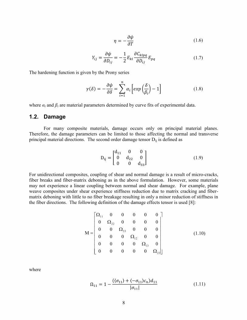
For many composite materials, damage occurs only on principal material planes. Therefore, the damage parameters can be limited to those affecting the normal and transverse principal material directions. The second order damage tensor Dij is defined as
For unidirectional composites, coupling of shear and normal damage is a result of micro-cracks, fiber breaks and fiber-matrix deboning as in the above formulation. However, some materials may not experience a linear coupling between normal and shear damage. For example, plane weave composites under shear experience stiffness reduction due to matrix cracking and fiber-matrix deboning with little to no fiber breakage resulting in only a minor reduction of stiffness in the fiber directions. The following definition of the damage effects tensor is used [8]:
where
(⟨ ⟩ ⟨ ⟩ )
| | (1.11)
[
] (1.9)
23
13
12
33
22
11
000000000000000000000000000000
(1.10)

9
(⟨ ⟩ ⟨ ⟩ )
| | (1.12)
(⟨ ⟩ ⟨ ⟩ )
| | (1.13)
√
√ (1.15)
√
√ (1.16)
and the c constants represent the crack closure coefficients. Thus, Ω represents the actual integrity in load directions and damage uniquely represents only tensile stiffness reduction in the normal direction or the ratio of crack area to total area. Based on the principle of energy equivalence, the damaged stiffness tensor Cijkl is related to the undamaged stiffness as
The damaged (actual) stresses and strains are (1.18)
(1.19) and the effective (local) stresses and elastic strains are (1.20)
(1.21) Thus, the damaged and effective configurations are related by (1.22)
(1.23) The explicit form of nominal thermodynamic force Yij is expanded in terms of effective strain in contracted form for tensile loading as
√ √
(1.14)
(1.17)

10
{
(
)
(
)
(
)
}
(1.24)
and compressive loading
{
( )
( )
( )
}
(1.25)
or any combination of the two. The damage surface g is assumed to have the form of a quadratic homogeneous function: ( )
⁄ ( ( ) ) (1.26)
where γo is the initial damage threshold and Jijkl is a positive definite fourth order tensor dependent upon strength parameters. Figure 1 shows an example of the damage surface in 2D stress space. An associated model, where the damage surface and damage potential are equal (g = f), is used.

11
Figure 1. Damage surface in 2D stress space (
).
For the analysis presented in Barbero’s book [1], g is given as a sum of the normal and shear components of the damage surface. At this time, this formulation is shown to be incorrect based on the evolution functions and the resulting tangent constitutive tensor because an explicit function for the separation does not exist and therefore not differentiable. Additionally, Barbero and De Vivo [2] implement an absolute value term in the damage surface that is linear with stress. The intermediate constants are not consistently solvable because the thermodynamic forces are independent of the sign of stress for the uniaxial cases. Therefore, this formulation is only applicable for very precise damage parameter combinations. The formulation presented above presents the same issue that the intermediate parameters are only functions of the tensile strength data. Thus, differences in compression and shear are accounted for by the integrity tensor definitions and the crack closure coefficients. Furthermore, even if a linear term is included in the damage surface definition, the Tsai-Wu criteria is not necessarily equivalent when γ + γo = 1. 1.2. Evolution Equations
The evolution of the internal variables can be described by the following flow rules
(1.27)
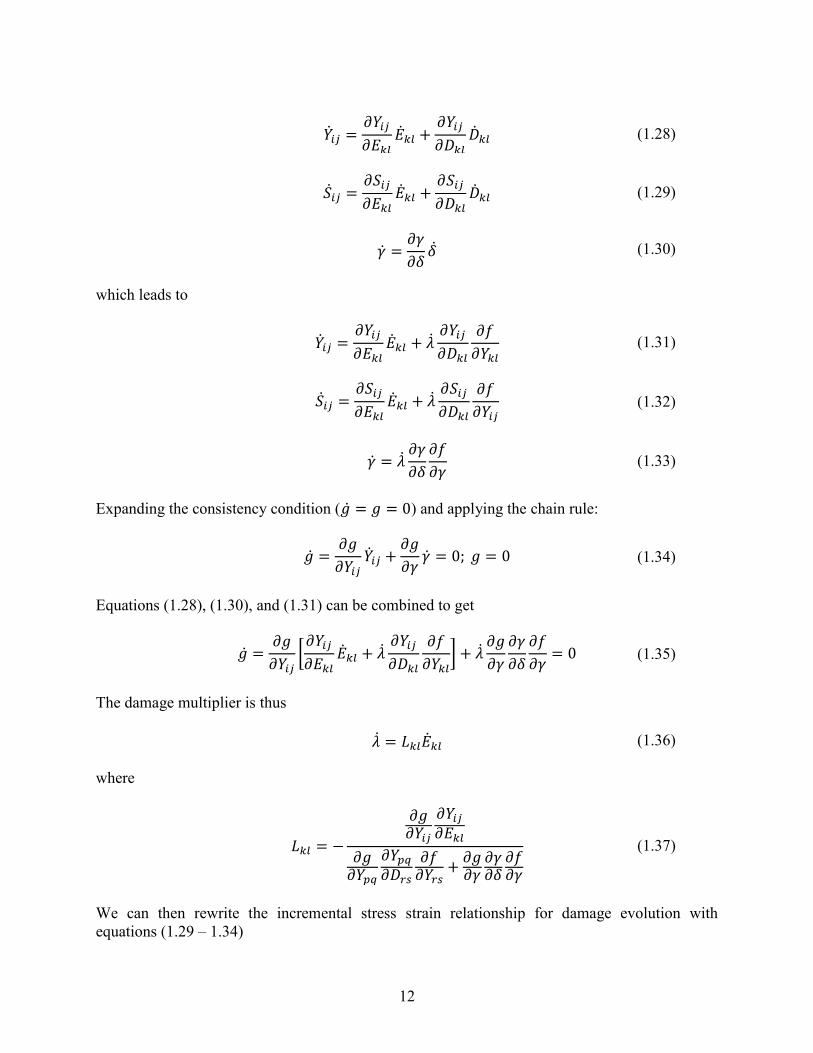
where λ is the damage multiplier. The incremental form of thermodynamic force, stress and hardening for damage evolution ( ) is given as
12
(1.29)
(1.30)
which leads to
(1.32)
(1.33)
Expanding the consistency condition ( ) and applying the chain rule:
(1.34)
Equations (1.28), (1.30), and (1.31) can be combined to get
[
]
(1.35)
The damage multiplier is thus (1.36) where
(1.37)
We can then rewrite the incremental stress strain relationship for damage evolution with equations (1.29 – 1.34)
(1.28)
(1.31)

13
(1.38)
The rate form of the damaged constitutive equation is given (1.39) Since the second terms of the above two equations must be equal, the tangent constitutive tensor is given as
(1.40)

14

15
2. SIERRA IMPLEMENTATION 2.1. Integration Scheme
When the damage activation function is greater than zero, additional damage occurs and the following integration scheme is invoked [1]. Rewrite equation (1.35) as
[
] (2.1)
Since the strain rate is constant for iteration k-1 to k in the integration scheme, linearization of the consistency equation for iteration k at timestep n+1 yields
( ) ( ) [
]
(2.2)
Solving for the damage multiplier increment at the converged iteration k where gk = 0 yields
( )
[
]
(2.3)
Then the damage state variables can be updated with the linearized flow rules as
( ) ( )
(
)
(2.5)
This procedure is repeated until | | and | | . 2.2. Small strain large deformation
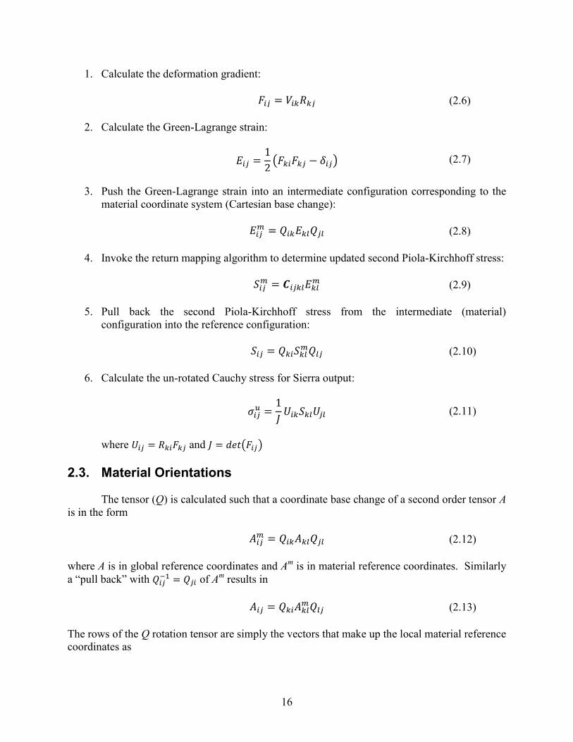
The previously described return mapping algorithm is used to solve the damage evolution of the stiffness tensor in a Kirchhoff material. Given that polymer matrix composites damage at low strain levels, this formulation is applicable to wide array of structures undergoing small strains and large rotations.
The material model accesses the updated left stretch (V) and rotation (R) tensors. However, an additional coordinate base change is needed to calculate strains in the material coordinate system. A proper orthogonal rotation tensor (Q) is calculated based on user input and coordinate system. This methodology is described in Section 2.3. The following outlines the Sierra implementation.
( ) ( )
(
)
(2.4)
16
1. Calculate the deformation gradient: (2.6)
2. Calculate the Green-Lagrange strain:
( ) (2.7)
3. Push the Green-Lagrange strain into an intermediate configuration corresponding to the
material coordinate system (Cartesian base change):
(2.8)
4. Invoke the return mapping algorithm to determine updated second Piola-Kirchhoff stress:
(2.9)
5. Pull back the second Piola-Kirchhoff stress from the intermediate (material)
configuration into the reference configuration:
(2.10)
6. Calculate the un-rotated Cauchy stress for Sierra output:
(2.11)
where and ( ) 2.3. Material Orientations
The tensor (Q) is calculated such that a coordinate base change of a second order tensor A is in the form
(2.12) where A is in global reference coordinates and Am is in material reference coordinates. Similarly a “pull back” with of Am results in
(2.13) The rows of the Q rotation tensor are simply the vectors that make up the local material reference coordinates as

17
where , and are the Cartesian coordinate unit vectors and , and are unit vectors in the primary material directions. The rotation tensor is calculated by using a series of rotations based on user defined coordinate system (RC) and three Euler angles ( , , ) given by spatially dependent functions. Q is generally defined as
( )( ( )) ( )( ( ))
( )( ( )) (2.17)
where Xa, Xb and Xc can be any global coordinate. The user defined coordinate system can be rectangular, cylindrical or spherical defined as vectors that make up . The general indices (1, 2, 3) for each coordinate direction will be: rectangular (x, y, z), cylindrical (r, θ, z) and spherical (r, θ, φ).
Rotation about the first axis: [
] (2.18)
Rotation about the second axis: [
] (2.19)
Rotation about the third axis: [
] (2.20)
where ( ) and ( ).
(2.14) (2.15) (2.16)

18

19
3. MATERIAL IDENTIFICATION
The following section outlines test data and procedures necessary for material parameter determination. Since the critical integrity parameter relates the actual remaining stiffness at failure to the undamaged stiffness, it is independent of crack closure coefficient. However, under compression the damage parameter is calculated as
( )
(3.1)
which maintains the definition of damage being the ratio of cracked area to total area and integrity being the actual remaining stiffness at failure.
If a linear term is included in the damage surface, the Tsai-Wu criteria is not analogous at γ + γo = 1 because of the independence of Y on the sign of stress for the uniaxial case. An independent critical value of γ is required for each loading condition. The value of the damage variable δ at failure can be determined by the ratio of the evolution equations
(3.2)
Integrating 3.2 for a monotonic uniaxial load, the critical damage evolution variables are
axial tension ( )
√ (3.3)
axial compression ( )
√
(3.4)
and in-plane shear (
)√
(3.5)
Where, Y1t, Y1c, Y1s and Y2s are the critical forces in tension, compression, axial due to shear and transverse due to shear respectively and for in-plane shear (3.5) axial damage is assumed zero.
(3.7)
( ) (
) (3.8)
(3.6)

20
( )(
) (3.9)
Similar equations are generated for transverse normal and out of plane shear stresses. The damage values at shear failure will be discussed later.
The damage surface threshold value is determined by a pure in-plane shear test, where the damage is expected to be the greatest. The shear stress at damage initiation is given as F4d and the state variable are δ = d11 = d22 = 0, thus the forces are
(3.10)
and plugging these into the damage surface and solving for γo we get
√ (3.11)
Since tension and compression are scaled by the crack closure terms, they can be solved independently. The intermediate tensor Jijkl and in-plane shear crack closure coefficient are solved by a set of three equations given in terms of
axial tensile failure
√ (3.12)
transverse tensile failure
√ (3.13)
in-plane shear failure
( (
( ) (
))
(
( )(
) )
)
(3.14)
with unknowns J11, J22, γo and . Furthermore it is assumed that damage in the fiber direction due to in-plane shear stresses is negligible. The in-plane shear failure relationship reduces to
(
) (3.16)
(
)
(3.17)
( )
(3.15)

21
The above equations are solved simultaneously using a numerical algorithm in Matlab, which can be obtained by contacting the author. Similar independent equations can be generated for axial, transverse and out of plane compression and out of plane shear loads for determining remaining crack closure coefficients.
The damage evolution coefficients are determined by a curve fit to a shear stress versus integrity curve. A simple minimization of the stress residuals at a given integrity is used. The model shear stress is related to integrity by the following relationship
√( )
(
)
(3.18)
where
∑ [ (
) ]
(3.19)
and
(
)
(
)
(3.20)
Since the intermediate parameters are functions of the evolution parameters the above
curve-fit must be solved iteratively. For a given test vector {α β}, the intermediate parameters are uniquely defined; providing a set of stress values to compare with the experimental data.
Standard tests are used to determine the elastic and strength properties. A pure shear test is conducted in order to determine the stress versus integrity curve. A monotonic load is possible if all damage is assumed elastic. However, unloading is necessary in order to determine stiffness at intermediate steps if significant plastic strains are present. For now we skip this step and present this data in terms of actual stress verses integrity. The Tables 1 and 2 give example data presented in [1].
Table 1. Elastic Properties
Property Value E11 142000 MPa E22 10300 MPa E33 10300 MPa ν12 0.21 ν13 0.21 ν23 0.38 G12 6420 MPa G13 6420 MPa G23 3710 MPa

22
Table 2. Directional Strengths
Property Value (Mpa) Integrity (Ω) F1t 1830 0.884 F2t 57.0 0.500 F3t 57.0 0.500 F1c 1082 0.889 F2c 57.0 0.500 F3c 57.0 0.500 F4 89.1 0.538 F5 89.1 0.538 F6 78.0 0.290 F4d (threshold) 17.8 1.00
A unique set of intermediate parameters exist for each set of evolution parameters α and
β. The evolution parameters are optimized by a simple constrained algorithm based on the sum of the squares of stress differences at each integrity value in the above data, where the stress values are obtained by solving the damage surface equations at each iteration. Table 3 gives the fitted parameters.
Table 3. Model Parameters
Property Value α 0.1144 β -0.1198 γo 0.0327 J11 0.0524 J22 1.5603 J33 1.5603 1.1953 1.0 1.0 1.0656 1.0656 1.0625

23
Figure 2. Shear stress verses shear integrity.
Notice the endpoints of the above plot are constrained to the damage initiation and failure points by the intermediate damage surface criterion. A preliminary verification is done with the curve fit, Matlab simulation version and the Abaqus UMAT under pure shear.
Figure 3. Shear stress verses shear integrity with model fits.
Since the curve fit assumes no damage in the fiber direction, this figure shows that although d1 is not strictly zero in the model, the differences are negligible. The above characterization is only one example of parameter estimation. If less data is available, optimization of the parameters is possible. Failure characterization using the critical thermodynamic force is possible [5] but will not be addressed in this report. Future work will focus on damage to failure and rate effects of woven composites.

24

25
4. EXAMPLE PROBLEMS 4.1. Shell like geometry orientations
A cone example is given to demonstrate orientation capabilities. An arbitrary hollow cone segment with a rounded end is modeled (Figure 5). The filament wound unidirectional composite cone consists of two layers. The inner layer is a series of longitudinal wraps and the outer layer is made up of hoop wraps. The orientation angle definition using spatial dependence is limited to geometries with large feature to thickness ratios.
The Elastic Orthotropic Damage material model uses up to three rotation angle functions with inputs (abscissa) one of the global x, y, z coordinates and axis of rotation defined in a user coordinate system.
The material rotations are shown in Figure 4a and 4b for arbitrary points in the inner and outer layers respectively. The fixed global coordinate system, shown in black, is used to define the point in x, y, z coordinates. These coordinates are then used to determine the local coordinates, shown in blue, based on a user defined coordinate system, in this case a cylindrical system as (R, θ, Z). Note the cylindrical Z axis corresponds to the global x. The resulting coordinate axes, designated with the subscript “Axis” serve as the initial material axes, where initially the moduli E11, E22 and E33 correspond to ERR, Eθθ and EZZ respectively. These local axes are then rotated to correspond to the desired material configuration, shown in green. In this case, both layers are rotated about the local θ (material 2) axis by αθ + 90⁰. The 90⁰ rotation is used to define the material 1 axis in-plane and the material 3 axis out-of-plane. Second, the outer (hoop) layer is rotated 90⁰ about the local material 3 axis. With each rotation, a new coordinate system is created; therefore, the subsequent rotations are completed on intermediate systems. The intermediate axis 1’ is shown as a green dashed line.
a. b.
Figure 4. Rotation definitions for longitudinal (a) and hoop (b) layers.

26
The following expression gives the orientation angle (αθ+90) for the curve between the
hoop and longitudinal layers. The transition from cone to dome is at x = 295.23, the dome centers are located at x = 309.12 and the inner and outer domes radii are r = 78.75 and r = 81.25 respectively.
begin function alpha_theta_inner
type is analytic
evaluate expression is "x <= 295.23 ? 10.0 + 90 : asin((309.12-x)/78.75)*180/pi + 90;"
end function alpha_theta_inner
#
begin function alpha_theta_outer
type is analytic
evaluate expression is "x <= 295.23 ? 10.0 + 90 : asin((309.12-x)/81.25)*180/pi + 90;"
end function alpha_theta_outer
Figure 5. Cross section showing out of plane normals (material 3).
4.2. Laminate Plate
Given is an example of modeling a 24 layer laminate plate (Fig. 6). Orientation angles are given in the global rectangular system as a piecewise constant function of depth (y). The 24 layers are simply modeled as 24 elements through the thickness. The angle function is shown in Fig. 7.

27
Figure 6. Laminate like angle distribution in a 3D solid.
Figure 7. Piecewise angle distribution as a function of through thickness direction (y).

28

29
5. CONCLUSIONS A general CDM orthotropic material model has been detailed and user guidance, material characterization and examples are provided. The resulting constitutive model is relevant for many composite materials. In addition, the thermodynamic framework and general orthotropic orientation capabilities provide adaptability for future damage evolution/failure models.

30

31
6. REFERENCES
[1] E. Barbero, Finite element analysis of composite materials, Boca Raton: CRC Press,
2008. [2] E. Barbero, and L. D. Vivo, “A constitutive model for elastic damage in fiber-reinforced
PMC lamina,” Int. J. of Dam. Mech., vol. 10, pp. 73-93, 2001. [3] P. Maimí, P. Camanho, J. A. Mayugo, and C. Dávila, “A continuum damage model for
composite laminates: Part I – Constitutive model,” Mech. of Mat., vol. 39, pp. 897-908, 2007.
[4] P. Maimí, P. Camanho, J. A. Mayugo, and C. Dávila, “A continuum damage model for composite laminates: Part II – Computational implementation and validation,” Mech. of Mat., vol. 39, pp. 909-919, 2007.
[5] Z. Hu, and Y. Zang, “Continuum damage mechanics based modeling progressive failure of woven-fabric composite laminate under low velocity impact,” J. of Zhejiang Univ. Sci. A, 2010.
[6] N. Hansen, and H. Schreyer, “A thermodynamically consistent framework for theories of elastoplasticity coupled with damage,” Int. J. Solids Struct., vol. 31, pp. 359-389, 1994.
[7] T. Belytschko, W. Liu, and B. Moran, Nonlinear Finite Elements for Continua and Structures, West Sussex, England: John Wiley & Sons, 2009.
[8] E. Barbero, G. Abdelal, and A. Caceres, “A micromechanical approach for damage modeling of polymer matrix composites,” Comp. Struct., vol. 67, pp. 427-436, 2004.

32

33
APPENDIX A: SIERRA MATERIAL MODEL SYNTAX Elastic Orthotropic Continuous Damage Mechanics Material Model: BEGIN MATERIAL <string>mat_name
DENSITY = <real>density_value
BIOTS COEFFICIENT = <real>biots_value
BEGIN PARAMETERS FOR MODEL ELASTIC_ORTHOTROPIC_DAMAGE
# General parameters (any two are required)
YOUNGS MODULUS = <real>youngs_modulus
POISSONS RATIO = <real>poissons_ratio
SHEAR MODULUS = <real>shear_modulus
BULK MODULUS = <real>bulk_modulus
LAMBDA = <real>lambda
# Required parameters
E11 = <real>e11
E22 = <real>e22
E33 = <real>e33
NU12 = <real>nu12
NU13 = <real>nu13
NU23 = <real>nu23
G12 = <real>g12
G13 = <real>g13
G23 = <real>g23
ALPHAD = <real>alphad
BETAD = <real>betad
GAMMA0 = <real>gamma0
J1 = <real>j1
J2 = <real>j2
J3 = <real>j3
CN11 = <real>cn11
CN22 = <real>cn22
CN33 = <real>cn33
CS12 = <real>cs12
CS13 = <real>cs13
CS23 = <real>cs23
ANGLE_1_ABSCISSA = <real>angle_1_abscissa
ANGLE_2_ABSCISSA = <real>angle_2_abscissa
ANGLE_3_ABSCISSA = <real>angle_3_abscissa
ROTATION_AXIS_1 = <real>rotation_axis_1
ROTATION_AXIS_2 = <real>rotation_axis_2
ROTATION_AXIS_3 = <real>rotation_axis_3
ANGLE_1_FUNCTION = <string>angle_1_function_name
ANGLE_2_FUNCTION = <string>angle_2_function_name
ANGLE_3_FUNCTION = <string>angle_3_function_name
COORDINATE SYSTEM = <string>coordinate_system_name
END [PARAMETERS FOR MODEL ELASTIC_ORTHOTROPIC_DAMAGE]

34

35
DISTRIBUTION 1 MS9042 M. Chiesa 8259 (electronic copy) 1 MS9042 M. Gonzales 8250 (electronic copy) 1 MS9042 S. Nelson 8259 (electronic copy) 1 MS9042 M. Veilleux 8259 (electronic copy) 1 MS9042 J. Dike 8259 (electronic copy) 1 MS9042 N. Spencer 8259 (electronic copy) 1 MS9106 T. Briggs 8226 (electronic copy) 1 MS9042 J. Foulk 8256 (electronic copy) 1 MS0845 J. Jung 1542 (electronic copy) 1 MS0845 K. Pierson 1542 (electronic copy) 1 MS0812 W. Scherzinger 1524 (electronic copy) 1 MS0899 Technical Library 9536 (electronic copy)

36

37