
A-2000 TM BISPECTRAL INDEX (BIS ) …frankshospitalworkshop.com/equipment/documents/ecg/...SECTION I...
92
Aspect Medical Systems A-2000 TM BISPECTRAL INDEX (BIS ) MONITORING SYSTEM S E R V I C E M A N U A L Caution: U.S. Federal law restricts this device to sale by or on the order of a physician. © Copyright, 1999, Aspect Medical Systems. All rights reserved. Copying or other reproduction of this document is prohibited without prior written consent of Aspect Medical Systems. Aspect Medical Systems, Inc. 2 Vision Drive Natick, MA 01760-2059 U.S.A. 508-653-0603 800-442-7688 [email protected] www.aspectms.com 075-0002 1.00
-
Upload
truongxuyen -
Category
Documents
-
view
214 -
download
0
Transcript of A-2000 TM BISPECTRAL INDEX (BIS ) …frankshospitalworkshop.com/equipment/documents/ecg/...SECTION I...

Aspect Medical Systems
A-2000TM
BISPECTRAL INDEX
(BIS) MONITORING SYSTEM
S E R V I C E M A N U A L
Caution: U.S. Federal law restricts this device
to sale by or on the order of a physician. © Copyright, 1999, Aspect Medical Systems. All rights reserved. Copying or other reproduction of this document is prohibited without prior written consent of Aspect Medical Systems. Aspect Medical Systems, Inc. 2 Vision Drive Natick, MA 01760-2059 U.S.A. 508-653-0603 800-442-7688
[email protected] www.aspectms.com 075-0002 1.00

TABLE OF CONTENTS
1. INTRODUCTION .............................................................................. 1-1
1.1 ABOUT THIS MANUAL ....................................................................................1-1
1.2 INTRODUCING THE A-2000 BIS MONITORING SYSTEM.............................1-2 1.2.1 Principal Components ................................................................................1-2 1.2.2 How The A-2000 Works .............................................................................1-3
1.3 INSTRUMENT IDENTIFICATION .....................................................................1-3 1.3.1 A-2000 Monitor ...........................................................................................1-3 1.3.2 A-2000 Digital Signal Converter .................................................................1-3 1.3.3 Software Revision Numbers .......................................................................1-3
1.4 PROPRIETARY INFORMATION AND DEVICES.............................................1-3
2. SAFETY PRECAUTIONS................................................................. 2-1 2.1.1 WARNINGS, CAUTIONS, AND NOTES....................................................2-1 2.1.2 Warnings: ...................................................................................................2-1 2.1.3 Cautions: ....................................................................................................2-3
2.2 KEY TO SYMBOLS ..........................................................................................2-5
3. PRINCIPLES OF OPERATION........................................................ 3-1
3.1 SYSTEM ARCHITECTURE...............................................................................3-1 3.1.1 The Digital Signal Converter (DSC)............................................................3-1 3.1.2 The A-2000 Monitor....................................................................................3-7 3.1.3 A-2000 Printer ............................................................................................3-8
4. PREPARATION FOR USE AND INSTALLATION ........................... 4-1
4.1 ENVIRONMENT ................................................................................................4-1 4.1.1 Shipping and Storage Environment............................................................4-1 4.1.2 Operating Environment...............................................................................4-1 4.1.3 Power Requirements and System Grounding ............................................4-2 4.1.4 Site Preparation..........................................................................................4-2
4.2 INSTRUMENT CONNECTIONS .......................................................................4-3 4.2.1 Digital Signal Converter Connections.........................................................4-3 4.2.2 Power Cord Connections............................................................................4-3 4.2.3 Printer Connector .......................................................................................4-3
4.3 INSTALLATION AND VERIFICATION PROCEDURE .....................................4-4
4.4 REPACKAGING FOR SHIPPING AND STORAGE..........................................4-4

5. PREVENTIVE MAINTENANCE, CARE AND CLEANING ............... 5-1
5.1 CARE AND CLEANING ....................................................................................5-1 5.1.1 Cleaning the Monitor and Digital Signal Converter.....................................5-1 5.1.2 Disinfecting the Monitor and Digital Signal Converter ................................5-1 5.1.3 Cleaning the Monitor Display......................................................................5-1
5.2 ROUTINE MAINTENANCE ...............................................................................5-2 5.2.1 Checking the Battery ..................................................................................5-2 5.2.2 Checking Leakage Current.........................................................................5-2 5.2.3 Monitor System Checkout Procedure.........................................................5-4 5.2.4 DSC Checkout Procedure ..........................................................................5-5 5.2.5 Patient Interface Cable (PIC) Checkout Procedure....................................5-5
6. DIAGNOSTICS AND TROUBLESHOOTING................................... 6-1
6.1 GENERAL TROUBLESHOOTING....................................................................6-1
6.2 THE A-2000 DIAGNOSTIC PROCEDURES.....................................................6-4 6.2.1 Power-Up Diagnostics ................................................................................6-4 6.2.2 Automatic Diagnostics ................................................................................6-8 6.2.3 Manual Diagnostics ..................................................................................6-13
7. DISASSEMBLING AND REASSEMBLING THE A-2000................. 7-1
7.1 REQUIRED TOOLS AND SUPPLIES...............................................................7-2
7.2 THE MONITOR CASE.......................................................................................7-3 7.2.1 Opening the Monitor Case..........................................................................7-3 7.2.2 Closing the Monitor Case ...........................................................................7-3
7.3 THE ELECTRO/LUMINESCENT DISPLAY......................................................7-7 7.3.1 Removing the E/L Display Board................................................................7-7 7.3.2 Reattaching the E/L Display Board.............................................................7-7
7.4 THE FRONT PANEL SWITCH SET..................................................................7-9 7.4.1 Removing the Switch Set ...........................................................................7-9 7.4.2 Installing the New Switch Set .....................................................................7-9
7.5 THE PRINTED CIRCUIT BOARD ASSEMBLY..............................................7-11 7.5.1 Removing the Printed Circuit Board assembly.........................................7-11 7.5.2 Installing the Printed Circuit Board Assembly...........................................7-11
7.6 THE MAIN PCB...............................................................................................7-14 7.6.1 Removing the Main PCB ..........................................................................7-14 7.6.2 Installing the Main PCB ............................................................................7-14
7.7 THE POWER SUPPLY PCB...........................................................................7-19 7.7.1 Removing the Power Supply PCB............................................................7-19 7.7.2 Installing the Power Supply PCB ..............................................................7-19

7.8 THE BATTERY................................................................................................7-22 7.8.1 Removing the Battery ...............................................................................7-22 7.8.2 Installing the Battery .................................................................................7-22
7.9 THE FAN .........................................................................................................7-24 7.9.1 Removing the Fan ....................................................................................7-24 7.9.2 Installing the Fan ......................................................................................7-24
7.10 THE CLAMP SHOE ASSEMBLY....................................................................7-26 7.10.1 Removing the Clamp Shoe Assembly......................................................7-26 7.10.2 Installing the Clamp Shoe Assembly........................................................7-26
7.11 FUSE REPLACEMENT...................................................................................7-27
8. A-2000 SPECIFICATIONS.............................................................. 8-1
8.1 GENERAL SPECIFICATIONS: .........................................................................8-1 8.1.1 Type of Protection against Electric Shock of the System:..........................8-3 8.1.2 Degree of Protection against Electric Shock of the System: ......................8-3 8.1.3 Degree of Protection against the Ingress of Water: ...................................8-3 8.1.4 Mode of Operation of the System:..............................................................8-3 8.1.5 Classification: .............................................................................................8-3
8.2 OPTIONS AND ACCESSORIES:......................................................................8-3
8.3 Digital Signal Converter (DSC) Connector....................................................8-4
8.4 WARRANTY ......................................................................................................8-5
9. APPENDICES .................................................................................. 9-1
9.1 APPENDIX I - A-2000 PARTS LIST................................................................9-1
9.2 APPENDIX II - SENSOR SIMULATOR - INSTRUCTIONS FOR USE ...........9-2

TABLE OF FIGURES
Figure 1-1 The A-2000 BIS Monitoring System................................................................1-4 Figure 1-2 Rear View of Monitor .....................................................................................1-5 Figure 3-1 The A-2000 System Block Diagram................................................................3-2 Figure 3-2 The A-2000 Signal Flow Diagram...................................................................3-3 Figure 3-3 The Digital Signal Converter (DSC)................................................................3-6 Figure 7-1 Opening the Monitor Case............................................................................7-5 Figure 7-2 The E/L Display Cable ...................................................................................7-5 Figure 7-3 The Keypad Cable Tension Flange ...............................................................7-6 Figure 7-4 The Four Mounting Screws............................................................................7-8 Figure 7-5 The Cable Access Port ................................................................................7-10 Figure 7-6 Remove the covering on the back of the new switch set.............................7-10 Figure 7-7 Place rear case assembly face down on a scratch free work surface.........7-13 Figure 7-8 Fan Cable ....................................................................................................7-13 Figure 7-9 Release standoff tab by squeezing with needle-nose pliers ........................7-15 Figure 7-10 The L bracket.............................................................................................7-15 Figure 7-11 Gently pull and flex to separate PCBs .......................................................7-16 Figure 7-12 Line up Interconnect PCB pins to Main PCB socket..................................7-16 Figure 7-13 Align standoffs and push in until standoff tabs snap into place .................7-17 Figure 7-14 Install L bracket by holding long side; short side connects to Main PCB...7-17 Figure 7-15 The L Bracket Installed ..............................................................................7-18 Figure 7-16 Gently flex and pull Power Supply PCB free of pins ..................................7-20 Figure 7-17 Remove four screws on rear of Power Supply PCB ..................................7-20 Figure 7-18 Remove shield from rear of Power Supply PCB........................................7-21 Figure 7-19 Battery and cable .......................................................................................7-23 Figure 7-20 Fan wiring orientation and Clamp Shoe screws ........................................7-25 Figure 7-21 Updated System with 2 Fan Mounting screws and Copper Tape..............7-25 Figure 7-22 Releasing the plastic locking tabs of the fuse holder.................................7-28 Figure 7-23 Re-installing the fuse holder ......................................................................7-28

SECTION I INTRODUCTION
- 1-1 -
SECTION I
1. INTRODUCTION
1.1 ABOUT THIS MANUAL This Service Manual contains information necessary to diagnose, troubleshoot and repair
the Aspect Medical Systems A-2000™ BIS Monitoring System. Also included are instructions for the unit’s installation, maintenance, care and cleaning. A parts list is provided in the appendices at the back of the manual. This manual is intended for Aspect Medical Systems service technicians and/or authorized Aspect distributors who have been trained by Aspect to perform the service procedures described within this manual. It assumes prior knowledge and experience with the internal workings of medical devices and electronics.
Caution: Refer to the section on disassembling and reassembling before attempting to service the inside of the A-2000.
Section I provides a functional overview of the A-2000, its principal components, and instrument identification. Section II discusses important safety precautions. Before attempting to set up or service the A-2000, please familiarize yourself with the safety information provided in this section. Section III describes the A-2000 monitor hardware and how it operates. Included are the assemblies and parts that make up the monitor and the Digital Signal Converter (DSC). Section IV provides preparation for use and installation instructions, including environmental considerations, instrument connections and system setup and check out. Section V describes normal maintenance, care and cleaning procedures. Section VI describes the A-2000 diagnostic tools and provides tables to aid in troubleshooting the system. Section VII describes the removal and replacement procedure for each subassembly.
Note: This manual was not designed for repairing the unit to the level of its individual components (e.g. the chips on the main board). The manual is intended solely for the troubleshooting and replacement of its subassembly modules (e.g. the electro-luminescent display and power supply).
Section VIII contains the A-2000 specifications. Appendix I contains a list of replaceable parts and subassemblies. Appendix II contains the Sensor Simulator instructions for use.

SECTION I INTRODUCTION
- 1-2 -
1.2 INTRODUCING THE A-2000 BIS MONITORING SYSTEM Aspect Medical Systems A-2000 BIS Monitoring System is a user-configurable patient monitoring system designed to monitor the hypnotic state of the brain based on acquisition and processing of EEG signals. The A-2000 processes raw EEG signals to
produce a single number, called the Bispectral Index, or BIS, which correlates to the patient’s level of hypnosis. It operates from an AC power source of 100V to 240V, 47/63Hz, and provides a minimum 20 minutes of automatic back-up battery power. The monitor is menu-driven with fixed keys for choosing the options available.
1.2.1 Principal Components The system is composed of a monitor and a digital signal converter, with a patient interface cable (PIC), and BIS Sensor. 1.2.1.1 Monitor The monitor contains the operator control panel, an electro-luminescent display screen, and connectors for the digital signal converter and printer. Front Panel Controls:
The [SILENCE] key toggles audible alarms on and off.
The left [←] and right [→] arrow keys are used to enter Review mode and to scroll data back and forth while in Review mode.
The [MENU/EXIT] key is used to enter and exit the Setup Menu. In Review mode it will return the user to the main screen. It is also used to halt certain procedures, such as the sensor check, and to answer "no" to a question.
The up [↑] and down [↓] arrows are used to move from one menu selection to another.
The [SELECT] key is used to move between menu selections, to confirm an entry, and to answer "yes" to a question.

SECTION I INTRODUCTION
- 1-3 -
1.2.1.2 Digital Signal Converter (DSC) The Digital Signal Converter is about the size of a computer mouse. It contains the EEG amplifiers and analog filters. The DSC digitizes EEG waveforms for transmission to, and processing by, the monitor. The DSC’s long flexible Monitor Interface Cable connects to the front of the monitor, and the shorter “DSC pigtail” cable connects to the Patient Interface Cable (PIC). The attachment clip on the DSC is used to secure it in a convenient location near the patient’s head. The patient connection is accomplished by attaching the Aspect BIS Sensor to the PIC.
1.2.2 How The A-2000 Works A detailed description of how the A-2000 works is contained within Section V of the A-2000 Operating Manual and will not be discussed in this Service Manual. Please refer to the A-2000 Operating Manual (070-0015) for additional information.
1.3 INSTRUMENT IDENTIFICATION
1.3.1 A-2000 Monitor Monitor identification information is permanently marked on the rear panel. This information includes instrument model and serial numbers, power ratings, cautions, and the Aspect Medical Systems shipping address.
1.3.2 A-2000 Digital Signal Converter The A-2000 Digital Signal Converter identification information is permanently marked on the rear panel of the Digital Signal Converter. This information includes instrument model and serial numbers and cautions.
1.3.3 Software Revision Numbers Software revision numbers are displayed in the Diagnostic Menu.
1.4 PROPRIETARY INFORMATION AND DEVICES Information and descriptions contained in this guide are the property of Aspect Medical Systems and may not be copied, reproduced or distributed without prior written permission. Portions of the A-2000 design are proprietary and are the subject of patents and patents pending.

SECTION I INTRODUCTION
- 1-4 -
Figure 1-1 The A-2000 BIS Monitoring System

SECTION I INTRODUCTION
- 1-5 -
Figure 1-2 Rear View of Monitor
Clamp
Shoe
Fuse
Holder
Serial
Port
Potential
Equalization
Terminal

SECTION I INTRODUCTION
- 1-6 -
SECTION II SAFETY PRECAUTIONS
- 2-1 -
SECTION II
2. SAFETY PRECAUTIONS
INTRODUCTION
Caution: Carefully read the entire A-2000 Operating Manual before using the monitor in a clinical setting.
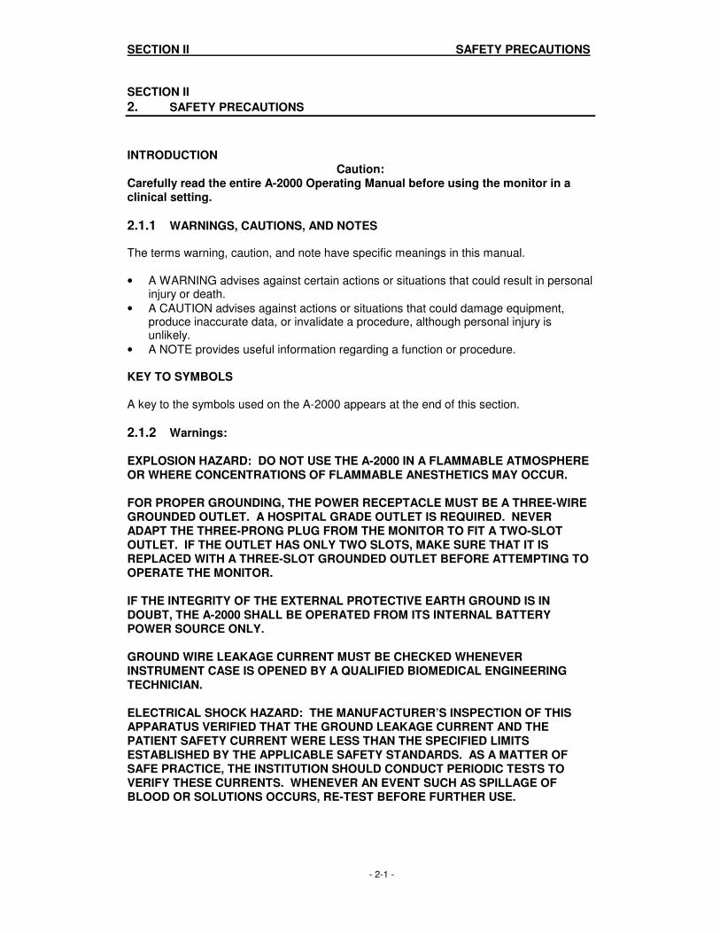
2.1.1 WARNINGS, CAUTIONS, AND NOTES The terms warning, caution, and note have specific meanings in this manual.
• A WARNING advises against certain actions or situations that could result in personal injury or death.
• A CAUTION advises against actions or situations that could damage equipment, produce inaccurate data, or invalidate a procedure, although personal injury is unlikely.
• A NOTE provides useful information regarding a function or procedure.
KEY TO SYMBOLS A key to the symbols used on the A-2000 appears at the end of this section.
2.1.2 Warnings: EXPLOSION HAZARD: DO NOT USE THE A-2000 IN A FLAMMABLE ATMOSPHERE OR WHERE CONCENTRATIONS OF FLAMMABLE ANESTHETICS MAY OCCUR. FOR PROPER GROUNDING, THE POWER RECEPTACLE MUST BE A THREE-WIRE GROUNDED OUTLET. A HOSPITAL GRADE OUTLET IS REQUIRED. NEVER ADAPT THE THREE-PRONG PLUG FROM THE MONITOR TO FIT A TWO-SLOT OUTLET. IF THE OUTLET HAS ONLY TWO SLOTS, MAKE SURE THAT IT IS REPLACED WITH A THREE-SLOT GROUNDED OUTLET BEFORE ATTEMPTING TO OPERATE THE MONITOR. IF THE INTEGRITY OF THE EXTERNAL PROTECTIVE EARTH GROUND IS IN DOUBT, THE A-2000 SHALL BE OPERATED FROM ITS INTERNAL BATTERY POWER SOURCE ONLY. GROUND WIRE LEAKAGE CURRENT MUST BE CHECKED WHENEVER INSTRUMENT CASE IS OPENED BY A QUALIFIED BIOMEDICAL ENGINEERING TECHNICIAN. ELECTRICAL SHOCK HAZARD: THE MANUFACTURER’S INSPECTION OF THIS APPARATUS VERIFIED THAT THE GROUND LEAKAGE CURRENT AND THE PATIENT SAFETY CURRENT WERE LESS THAN THE SPECIFIED LIMITS ESTABLISHED BY THE APPLICABLE SAFETY STANDARDS. AS A MATTER OF SAFE PRACTICE, THE INSTITUTION SHOULD CONDUCT PERIODIC TESTS TO VERIFY THESE CURRENTS. WHENEVER AN EVENT SUCH AS SPILLAGE OF BLOOD OR SOLUTIONS OCCURS, RE-TEST BEFORE FURTHER USE.

SECTION II SAFETY PRECAUTIONS
- 2-2 -
UNIVERSAL PRECAUTIONS SHALL BE OBSERVED TO PREVENT CONTACT WITH BLOOD OR OTHER POTENTIALLY INFECTIOUS MATERIALS. PLACE CONTAMINATED MATERIALS IN REGULATED WASTE CONTAINER. DO NOT MIX DISINFECTING SOLUTIONS (e.g. BLEACH AND AMMONIA) AS HAZARDOUS GASES MAY RESULT. ELECTRICAL SHOCK HAZARD: DO NOT REMOVE MONITOR COVERS DURING OPERATION OR WHILE POWER IS CONNECTED TO MONITOR. FOR CONTINUED PROTECTION AGAINST FIRE OR DAMAGE, ALWAYS REPLACE OLD FUSE WITH THE SAME FUSE TYPE AND RATING. ANY PROCEDURES THAT REQUIRE THE REMOVAL OF THE MONITOR’S COVER AND INTERNAL PARTS SHOULD BE PERFORMED BY A QUALIFIED BIOMEDICAL ENGINEERING TECHNICIAN. POWER OFF THE UNIT USING THE POWER SWITCH. UNPLUG THE MONITOR BEFORE DISASSEMBLING/ REASSEMBLING THE A-2000. IF METAL COMES IN CONTACT WITH THE TERMINALS ON THE BATTERY, IT COULD RESULT IN PERMANENT DAMAGE TO THE BATTERY AND IS AN ELECTRICAL SHOCK HAZARD. DUE TO THE BATTERY OPERATION POSSIBLE WITH NO AC CONNECTED, EXTREME CARE MUST BE USED WHEN DISASSEMBLING AND ASSEMBLING THE A-2000 MONITOR. WITH AC DISCONNECTED AND BATTERY POWER ON, HIGH VOLTAGE IS PRESENT ON THE E/L DISPLAY AND POWER SUPPLY PCB. DO NOT ACTIVATE POWER ON SWITCH WITH CASE OPEN! SHOCK HAZARD: DO NOT ATTEMPT TO DISCONNECT THE POWER CORD WITH WET HANDS. MAKE CERTAIN THAT YOUR HANDS ARE CLEAN AND DRY BEFORE TOUCHING THE POWER CORD. FOR A-2000s USED OUTSIDE OF NORTH AMERICA: A HARMONIZED LINE CORD WITH CONDUCTORS HAVING A CROSS SECTIONAL AREA GREATER THAN 0.75 MM
2 MUST BE USED.
THE CONDUCTIVE PARTS OF ELECTRODES OR SENSOR AND CONNECTORS, INCLUDING THE NEUTRAL ELECTRODE, SHOULD NOT CONTACT OTHER CONDUCTIVE PARTS INCLUDING EARTH. TO REDUCE THE HAZARD OF BURNS IN THE HIGH FREQUENCY SURGICAL NEUTRAL ELECTRODE CONNECTION, THE SENSOR OR ELECTRODES SHOULD NOT BE LOCATED BETWEEN THE SURGICAL SITE AND THE ELECTRO-SURGICAL UNIT RETURN ELECTRODE. TO MINIMIZE THE RISK OF PATIENT STRANGULATION, THE PATIENT INTERFACE CABLE (PIC) MUST BE CAREFULLY PLACED AND SECURED. BE SURE MONITOR IS MOUNTED SECURELY IN PLACE TO AVOID PERSONAL INJURY.

SECTION II SAFETY PRECAUTIONS
- 2-3 -
WHEN CONNECTING EXTERNAL EQUIPMENT (e.g. DATA CAPTURE COMPUTER), THE SYSTEM LEAKAGE CURRENT MUST BE CHECKED AND MUST BE LESS THAN THE IEC601-1-1 LIMIT. THE USE OF ACCESSORY EQUIPMENT NOT COMPLYING WITH THE EQUIVALENT SAFETY REQUIREMENTS OF THIS EQUIPMENT MAY LEAD TO A REDUCED LEVEL OF SAFETY OF THE RESULTING SYSTEM. CONSIDERATION RELATING TO THE CHOICE SHALL INCLUDE:
• USE OF THE ACCESSORY IN THE PATIENT VICINITY;
• EVIDENCE THAT THE SAFETY CERTIFICATION OF THE ACCESSORY HAS BEEN PERFORMED IN ACCORDANCE TO THE APPROPRIATE IEC 601-1 AND/OR IEC 601-1-1 HARMONIZED NATIONAL STANDARD.
FAN WIRE MUST BE POSITIONED AS SHOWN IN FIG. 7-21. INCORRECT ROUTING OF FAN WIRE MAY RESULT IN A HAZAROUS CONDITION.
2.1.3 Cautions: U.S. Federal law restricts this device to sale by or on the order of a physician. Refer to the section on disassembling and reassembling before attempting to service the inside of the A-2000. Carefully read the entire A-2000 Operating Manual before using the monitor in a clinical setting. Periodically check the battery by operating an A-2000 that has been disconnected from the wall socket and which has been charging the battery for at least four hours. After long periods of storage (e.g. > 1 month) it may be necessary to cycle (discharge, then charge) the battery a few times to get full charge capacity. If the A-2000 fails to operate reliably from the battery for twenty minutes, battery replacement is required. The A-2000 contains an internal Nickel-Metal-Hydride battery. The battery must be removed by a qualified service technician and disposed of or recycled in accordance with the national laws of the country. Contact Aspect Medical Systems, Inc. or the local distributor for a replacement battery. A burned out fuse usually indicates a serious problem with the electrical system of the A-2000 unit. Call service before attempting to remove and replace a fuse. If metal comes in contact with the battery terminals, permanent damage to the battery and other connecting parts could result. Do not autoclave the Digital Signal Converter or Monitor. Autoclaving will seriously damage both components. Do not submerge. Do not block fan output. Keep at least three full inches of unobstructed space between rear of instrument and wall and other instruments. Do not allow other instruments to block airflow. Do not block ventilation inlet holes on the underside of monitor.

SECTION II SAFETY PRECAUTIONS
- 2-4 -
Do not open Digital Signal Converter for any reason. The seal to prevent liquids from entering the Digital Signal Converter may be damaged if opened. Service or repairs must be performed only by qualified biomedical technicians. The A-2000 has been designed to operate with a disposable BIS Sensor. The sensor is a silver/silver chloride electrode array that utilizes Aspect’s patented
Zipprep technology and uses a proprietary connector. Use of incorrect types of electrodes may result in intermittent loss of signal or poor signal quality. Continuous impedance checking may need to be disabled if the 1 nanoampere 128 Hz impedance check signal interferes with other equipment, e.g., evoked potential monitors.
VERY IMPORTANT! Use only the Loctite number specified. Using the incorrect Loctite will damage plastic components. Use only the parts and tools specified. Use of any others may damage the instrument. Failure to position E/L Display screen gasket properly may result in a monitor that will allow fluid to leak in when the display is cleaned. Replace battery only with same type of approved battery. Use of non-approved battery may result in incorrect operation or damage to the monitor.
A-2000 is a trademark and Bispectral Index, BIS and Zipprep are registered trademarks of Aspect Medical Systems, Inc.

SECTION II SAFETY PRECAUTIONS
- 2-5 -
2.2 KEY TO SYMBOLS
ON (power; connection to the mains)
OFF (power; disconnection from the mains)
Audible Alarm Silenced
Operating on Battery
Type BF Equipment
Attention, Consult Accompanying Documents
J1
Attention, J1 RS-232 Serial Port, Consult Accompanying Documents
J2
Attention, J2 Printer Port, Consult Accompanying Documents

SECTION II SAFETY PRECAUTIONS
- 2-6 -
Fuse, Replace only with same Type and Rating
Equipotential
Alternating Current
Dangerous Voltage
Protective Earth (ground)
Storage Temperature Limits

SECTION III PRINCIPLES OF OPERATION
- 3-1 -
SECTION III
3. PRINCIPLES OF OPERATION
The A-2000 BIS Monitoring System consists of:
• The BIS monitor with built-in battery backup and detachable power cord
• The Digital Signal Converter (DSC)
• Aspect’s BIS Sensor Patient Interface Cable (PIC) and BIS Sensor This section describes the architecture of the A-2000 monitor and DSC and how their constituent parts interact.
3.1 SYSTEM ARCHITECTURE Hardware is divided into two main components: the monitor and the digital signal converter (DSC). The A-2000 monitor contains the circuits for digitally processing the EEG data, computing the processed parameters, and displaying the waveforms and processed parameters. The circuits to acquire and digitize the EEG signals reside in the Digital Signal Converter (DSC). The monitor also contains the circuits for powering the monitor, DSC, and companion printer. Integral to these circuits is a battery backup. Printer function is not available while on battery backup. A block diagram depicting the monitor subassemblies appears in Figure 3-1. A signal flow diagram appears in Figure 3-2. After passing through input protection circuits in the DSC, the EEG signals are differentially amplified and filtered to remove DC and high frequency components. The signals are digitized by separate one bit sigma-delta analog to digital converters. The outputs from the converters are multiplexed onto the DSC communications line and de-multiplexed in the monitor prior to being fed to the Digital Signal Processor (DSP). The DSP filters the signals and computes the processed variables. The results are passed to the host CPU for display.
3.1.1 The Digital Signal Converter (DSC) The DSC contains the inputs, amplifiers, and digitizers for two channels of EEG. It has a single point connection that connects via a Patient Interface Cable (PIC) to a BIS Sensor. The A-2000 is designed to process one channel using the BIS Sensor, the A-2000 and DSC hardware is capable of two channels. The sensor and PIC contains circuits for identifying them to the monitor. This permits the monitor to configure automatically. The DSC constantly monitors the combined source impedance at its inputs, and also has facility for measuring the individual impedance of the channel and ground electrodes. There are circuits for injecting self-test voltages into the amplifier inputs.

SECTION III PRINCIPLES OF OPERATION
- 3-2 -
Figure 3-1 The A-2000 System Block Diagram

SECTION III PRINCIPLES OF OPERATION
- 3-3 -
Figure 3-2 The A-2000 Signal Flow Diagram

SECTION III PRINCIPLES OF OPERATION
- 3-4 -
3.1.1.1 The DSC’s Preamplifier Board The preamplifier board contains the input protection circuits, montage mode switches, differential amplifiers, filter and gain amplifiers, impedance test circuits, self test circuits, and parts of the sensor ID circuit. 3.1.1.2 DSC Signal Conditioning The input protection circuits are designed to protect the inputs from destruction by electric shock from sources such as electrostatic discharge (ESD) or defibrillation. The protection circuits also reduce the effects of high frequency ambient noise from sources such as electro-cautery and other devices. The montage mode switches follow the protection circuits. These switches configure the inputs appropriately for the sensor. The signals are amplified by instrumentation amplifiers which have a fixed gain. The amplifiers have DC servos which remove the signals below high pass cutoff frequency. In the event of amplifier overload, the servos are changed to a higher frequency to facilitate fast recovery (blocking) under control of the host processor. Each channel is further amplified to the level required by the A/D converters. The amplifiers also serve as filters to prevent aliasing by the converters. 3.1.1.3 DSC Impedance Testing In the default state of the DSC the combined channel electrodes’ impedance is continuously checked. A small current (approximately 1 nanoampere) is injected into each electrode at 128 Hz, just above the EEG band. The resulting voltages are measured. Equal but opposite currents are injected into the (+) and (-) electrodes simultaneously while the digital signal processor measures the resulting voltage. BIS monitoring is performed while combined impedance is checked. The DSC can also measure the individual electrode impedance by injecting current into the REF electrode only. Individual electrode impedance is derived by subtracting the resulting value from the combined value. BIS monitoring is interrupted while individual impedance is checked. The ground electrode impedance is also measured while injecting current into the REF electrode. BIS monitoring is interrupted while the ground impedance is checked. The impedance check signal can occasionally interfere with other monitoring equipment connected to the patient. Evoked potential monitors are particularly susceptible because they use a wide bandwidth. The automatic impedance check feature can be turned off by selecting “Impedance Checking – OFF” in the Diagnostics Menu (See Operating Manual for specific instructions).

SECTION III PRINCIPLES OF OPERATION
- 3-5 -
3.1.1.4 The DSC Communications Board The communications board contains the analog to digital (A/D) converter for each channel, the monitor interface, the sensor interface and the power supply circuits. A crystal controlled DSC master clock is on this board. This clock is the system’s BIS processing clock. A/D Conversion (Patented technology) The communications board contains sigma-delta modulators for the two channels. These run at 16384 samples per second. Test Signal A calibrated test signal is generated on the communications board during DSC self test. The signal is a 2 Hz square wave of approximately +/-50µV. It is applied to the inputs of the differential amplifiers, resulting in a test of the entire signal path except for the input connections and protection circuits. During self test noise, gain and frequency response are checked. Interface to the Monitor (Patented technology) The outputs from the two channels are multiplexed in a field programmable gate array (FPGA). Multiplexed with the EEG data is status information such as DSC identification, mode (bipolar or referential), lead off indication, and power supply faults. The status information is only transmitted on command from the host. The output is transformer coupled onto a balanced twisted pair line. The transformer provides the required patient isolation. The communications board decodes the control information coming from the host via a command line. Commands such as “block” amplifier saturation and conduct impedance tests are transmitted. DSC Power Supply (Patented technology) The DSC derives power from the command line. The line is balanced twisted pair coupled via a transformer on the communications board. The isolated signal is rectified and linearly regulated to provide DSC power. 3.1.1.5 The DSC Mechanicals The DSC is contained in a small custom designed plastic case about the size of a computer mouse (see Figure 3-3). It is connected to the monitor via a narrow, highly flexible cable. The case has one large eyelet at the corner to allow the user to use a strap to hang the DSC or pin it to the bed sheets. The patient connection is accomplished with an Aspect BIS Sensor for low and balanced impedance. The Patient Interface Cable pigtail and the monitor cables are strain relieved and permanently attached to the case. A proprietary connector is used for the patient interface cable connection and a high quality plastic connector is used for connection to the monitor. There are no ventilation holes in the DSC case. It will not leak when splashed with liquids. The case is electrically shielded both to prevent spurious emissions from the DSC and to prevent externally caused interference with the DSC circuits.

SECTION III PRINCIPLES OF OPERATION
- 3-6 -
Figure 3-3 The Digital Signal Converter (DSC)
DSC - 2 Monitor Interface Cable
DSC pigtail
Patient Interface Cable (PIC)

SECTION III PRINCIPLES OF OPERATION
- 3-7 -
3.1.2 The A-2000 Monitor The A-2000 monitor contains the circuits for digitally processing the EEG data, computing the processed parameters, and displaying the waveforms and processed parameters. The circuits for acquiring the EEG signal and digitizing them reside in the digital signal converter (DSC). The monitor also contains the circuits for powering the monitor, DSC, and companion printer. Printer function is not available on battery backup. A block diagram depicting the monitor subassemblies appears in Figure 3-1. A signal flow diagram appears in Figure 3-2. The signals are acquired and digitized by the DSC. The DSC multiplexes the signals onto the DSC communications line. The EEG signals are de-multiplexed in the monitor and fed to the Digital Signal Processor (DSP). The processor filters and down-samples them, calculates the processed parameters, and outputs the data display. 3.1.2.1 The Main Board The Main board contains the Digital Signal Processors, the Host processor, data memory, real time clock, and DSC interface. All software and firmware can be downloaded through the serial port. 3.1.2.2 Digital Signal Processor The functions of the DSP include: decimation filters for up to 2 channels of EEG data, computation of processed EEG parameters, control of the DSC, and interface with the host. 3.1.2.3 Host Processor The functions of the host processor include: control of the display, interface with the keypad, serial port, and printer, control of monitor boot up and download, control of memory. An on board annunciator is included for generating alarm sounds. The display interface is a 4-bit LCD type. The serial port is standard RS-232. The printer interface is a non-standard serial type with extra lines for printer keys and printer control and status. It is designed to interface with a Seiko printer interface board. 3.1.2.4 The Digital Signal Converter (DSC) Interface The DSC interface is composed of two unidirectional bi-phase encoded serial lines, one going to the DSC and another bringing data from the DSC. The power to the interface is under software control. An overcurrent detector circuit monitors current to the DSC. If the current exceeds the expected value, the power is shut off to the DSC by the hardware, and the DSP is notified.
SECTION III PRINCIPLES OF OPERATION
- 3-8 -
3.1.2.5 The Interconnect Board The A-2000 monitor is designed with a minimum of internal cabling. The Interconnect board provides the physical mounting and electrical connections for the major subassemblies of the A-2000. It has mounted to it the power input module (connector for the AC power cord and associated fuses), the equipotential stud, the power switch, and connectors for the printer (external), the serial port (external) and the various internal connectors for the Main PCB, Switch pad, battery, and fan. 3.1.2.6 The Power Supply The power supply runs from ac power from 100-240 VAC, 50-60 Hz. It provides +5 V (at 6 A) and +12 V (at 0.72 A) outputs and charges the battery (6-cell NiMH) 7.2 V (nominal), 1800 mA. Signals are provided to the processor to indicate AC FAIL, RESET, and LOW BATTERY. The power supply switches the rectified AC line at 125 kHz. The output drives the primary of a step-down transformer that also provides isolation from the ac line. The left side of the power supply is referenced to AC line and the right side to ground. The transformer secondary has two outputs which are rectified and filtered to create + 5 V and + 10 V outputs. The +10 V signal drives a DC-to-DC converter to create the +12 V output and charges the battery. The battery driven supply switches the +10 V output at 125 kHz using a pulse width modulated buck circuit to create the +5 V output. The battery voltage feeds the input of the same DC-to-DC converter to create the +12 V output. 3.1.2.7 The Battery The battery is for backup use only. Its life is approximately 5 years or 200 charge and discharge cycles, whichever occurs first. The battery is a six-cell arrangement including temperature and current control elements, and has a nominal output of 7.2 volts DC. The battery is charged only when the A-2000 Monitor is turned on and running from AC power. It is capable of supporting monitor operation for a minimum of 20 minutes. Printer use is not enabled during battery operation. 3.1.2.8 The Fan A fan is located on the rear panel of the chassis. The fan keeps the temperature rise inside the chassis to within approximately 10 degrees of the ambient temperature.
3.1.3 A-2000 Printer The printer is fastened to the monitor bottom and is connected mechanically and electrically (no cable required). The printer interface is compatible only with the optional A-2000 printer.

SECTION IV PREPARATION FOR USE AND INSTALLATION
- 4-1 -
SECTION IV
4. PREPARATION FOR USE AND INSTALLATION
INTRODUCTION This section provides installation instructions for the Aspect A-2000 BIS Monitor, Digital Signal Converter and accessories including:
• Site preparation
• Instrument connections
• Installation and verification procedure
• Repackaging for shipping and storage
4.1 ENVIRONMENT
4.1.1 Shipping and Storage Environment The monitor and its accessories can be stored or shipped within the following environmental limits. Note that these limits apply to non-operational storage and shipping situations. Temperature -20
oC to +60
oC
Humidity 15 % to 95 % (non-condensing) Pressure 360 mmHg to 800 mmHg Protect the monitor from sudden temperature changes which can lead to condensation within the instrument. To minimize condensation, avoid moving the system between heated buildings and outside storage. Once moved inside, allow the monitor to stabilize in the unopened shipping container at the inside ambient temperature before unpacking and placing into service. Before operation, wipe down all visible condensation and allow the system to reach equilibrium at room temperature.
4.1.2 Operating Environment The A-2000 is not designed for use in areas containing flammable gases or vapors.
WARNING: EXPLOSION HAZARD: DO NOT USE THE A-2000 IN A FLAMMABLE ATMOSPHERE OR WHERE CONCENTRATIONS OF FLAMMABLE ANESTHETICS MAY OCCUR.
Temperature. The Aspect A-2000 Monitor is designed to operate safely at a room temperature of 5 degrees C to 40 degrees C. Conditions that exceed these limits could affect reliability. Humidity. The monitor is designed to operate within specifications at a relative non-condensing humidity of 15% to 95%. Pressure. The monitor will operate satisfactorily at or above sea level, and is unaffected by extremes or changes in altitude within atmospheric pressures of 360 mmHg to 800 mmHg.
SECTION IV PREPARATION FOR USE AND INSTALLATION
- 4-2 -
4.1.3 Power Requirements and System Grounding The A-2000 BIS Monitor requires a power source of 100-240 VAC, 50-60Hz. Current consumption is 1 ampere maximum (including printer load). To protect operating personnel and patients, the monitor must be properly grounded. Accordingly, the monitor is equipped with a hospital grade line cord. The power cord grounds the system to the power line ground when plugged into an appropriate 3-wire receptacle.
WARNING: FOR PROPER GROUNDING, THE POWER RECEPTACLE MUST BE A THREE-WIRE GROUNDED OUTLET. A HOSPITAL GRADE OUTLET IS REQUIRED. NEVER ADAPT THE THREE-PRONG PLUG FROM THE MONITOR TO FIT A TWO-SLOT OUTLET. IF THE OUTLET HAS ONLY TWO SLOTS, MAKE SURE THAT IT IS REPLACED WITH A THREE-SLOT GROUNDED OUTLET BEFORE ATTEMPTING TO OPERATE THE MONITOR. IF THE INTEGRITY OF THE EXTERNAL PROTECTIVE EARTH GROUND IS IN DOUBT, THE A-2000 SHALL BE OPERATED FROM ITS INTERNAL BATTERY POWER SOURCE ONLY. FOR A-2000s USED OUTSIDE OF NORTH AMERICA: A HARMONIZED LINE CORD WITH CONDUCTORS HAVING A CROSS SECTIONAL AREA GREATER THAN 0.75 MM
2 MUST BE USED.
4.1.4 Site Preparation The compact size of the monitor allows it to be easily installed in most hospital OR settings without special site preparation. Optional mounting accessories (see Section 2.2.5 of the Operating Manual) are available to secure the monitor to an anesthesia cart or IV pole, or to allow for secure and stable placement of the monitor on a flat surface.

SECTION IV PREPARATION FOR USE AND INSTALLATION
- 4-3 -
4.2 INSTRUMENT CONNECTIONS Detailed connection instructions are provided in the A-2000 Operating Manual, Section III.
4.2.1 Digital Signal Converter Connections The long flexible cable from the A-2000 Digital Signal Converter connects to the electrically isolated digital signal converter connector on the front panel of the monitor. Once connected, the DSC need not be disconnected again. However, if you wish to disconnect the DSC cable from the monitor, carefully reach as far as possible into the port opening with your thumb and index finger, squeeze and pull back on the gray cylindrical connector housing. Do not twist or pull on cord.
4.2.2 Power Cord Connections The A-2000 is designed to use only 3 - conductor IEC hospital-grade power cords. Check for a firm connection.
4.2.3 Printer Connector This printer port connector is designed to connect only to the Aspect A-2000 printer for screen prints. To connect: 1. Turn OFF the monitor. 2. Align the printer connectors located on the bottom of the monitor and top of the printer
so that they mate correctly. 3. Secure the printer to the monitor with the mounting screw located in the base of the
printer. Use caution not to cross-thread the mounting screw. 4. Turn on the monitor.

SECTION IV PREPARATION FOR USE AND INSTALLATION
- 4-4 -
4.3 INSTALLATION AND VERIFICATION PROCEDURE 1. Open packages and inspect for all components:
• Monitor with power cable
• DSC (Digital Signal Converter)
• PIC (Patient interface cable) You will also need a BIS Sensor or Sensor Simulator. 2. Connect power cable to monitor, plug power connector into appropriate wall outlet. 3. Power up monitor by pressing power button (lower right side of case).
• Verify beep tone as power button is activated
• Verify fan (rear case wall) moves air outward.
• Verify that self-test procedure completes successfully (approx. 30 seconds).
• Verify next screen says ‘CONNECT DSC CABLE TO FRONT OF MONITOR’ 4. Connect DSC, with PIC and Sensor. (Refer to the A-2000 Operating Manual, Section
III for detailed instructions.)
• Verify that DSC test completes
• Verify SENSOR CHECK screen displays. 5. Exit from SENSOR CHECK screen by passing impedance check or by exiting with
MENU/EXIT key. 6. Disconnect power cord.
• Verify ‘OPERATING ON BATTERY BACKUP (E33)’ is displayed.
• Verify battery icon displays in BIS banner (top left corner of screen). 7. Reconnect power cord.
• Verify battery icon is not displayed in BIS banner.
• Verify no ‘OPERATING IN BATTERY BACKUP (E33) DISPLAY 8. Do keyboard checkout:
• Press SILENCE key Verify icon shows at BIS banner
• Press Review ARROW BACK key Verify REVIEW MODE Menu displays
• Press MENU/EXIT key Verify REVIEW MODE MENU exits,
• Press Review ARROW AHEAD key Verify REVIEW MODE Menu displays
• Press MENU/EXIT key Verify REVIEW MODE MENU exits
• Press MENU/EXIT key Verify Setup Menu displays
• Press UP ARROW key Verify highlight bar moves up with each press.
• Press DOWN ARROW key Verify highlight bar moves down with each press.
• Press SELECT key Verify that highlighted menu line is selected.
• Press MENU/EXIT Verify that Setup Menu exits
9. End of installation.
4.4 REPACKAGING FOR SHIPPING AND STORAGE If it becomes necessary to return the monitor to the factory, use the original shipping container to protect the product. Seal the package with reinforced packing tape rather than plastic or masking tape. Mark shipping or storage container FRAGILE.

SECTION V PREVENTIVE MAINTENANCE, CARE AND CLEANING
- 5-1 -
SECTION V
5. PREVENTIVE MAINTENANCE, CARE AND CLEANING
INTRODUCTION This section describes:
• Care and cleaning procedures
• Routine maintenance
5.1 CARE AND CLEANING
WARNING: UNIVERSAL PRECAUTIONS SHALL BE OBSERVED TO PREVENT CONTACT WITH BLOOD OR OTHER POTENTIALLY INFECTIOUS MATERIALS. PLACE CONTAMINATED MATERIALS IN REGULATED WASTE CONTAINER.
5.1.1 Cleaning the Monitor and Digital Signal Converter Clean any spillage of blood or solutions on either the monitor or Digital Signal Converter as soon as possible. Dried blood is very difficult to remove. Use lint-free absorbent towels for spill cleanups. Dampen the towel with detergent and lukewarm water to aid in cleaning.
5.1.2 Disinfecting the Monitor and Digital Signal Converter Use lint free absorbent towels dampened with 10% bleach solution, or a commercial disinfectant (e.g. Lysol Professional Disinfectant Foam Cleaner Spray or PDI Germicidal Disposable Wipes).
WARNING: WHENEVER AN EVENT SUCH AS SPILLAGE OF BLOOD OR SOLUTIONS OCCURS, RE-TEST GROUND LEAKAGE CURRENT BEFORE FURTHER USE. DO NOT MIX DISINFECTING SOLUTIONS (e.g. BLEACH AND AMMONIA) AS HAZARDOUS GASES MAY RESULT.
Caution: Do not autoclave the Digital Signal Converter or Monitor. Autoclaving will seriously damage both components. Do not submerge.
After cleaning, dry all areas except the monitor display screen (see below) with a lint-free absorbent paper towel.
5.1.3 Cleaning the Monitor Display Clean the monitor display screen with a mild solution of detergent and warm water, or a commercial display screen cleaner, available through personal computer dealers. To avoid scratching the screen, never use abrasive cleaners.

SECTION V PREVENTIVE MAINTENANCE, CARE AND CLEANING
- 5-2 -
5.2 ROUTINE MAINTENANCE The A-2000 monitor is designed so that no periodic adjustment or calibration is required.
5.2.1 Checking the Battery The battery must be tested periodically to verify that the A-2000 will continue to operate during power outages. To test: 1. Charge the A-2000 by leaving it plugged in with the power ON for 4 hours. 2. Disconnect the A/C cord from wall supply 3. Verify that the A-2000 operates reliably for a minimum of 20 minutes. 4. Recharge the battery.
Caution: Periodically check the battery by operating an A-2000 that has been disconnected from the wall socket and which has been charging the battery for at least four hours. After long periods of storage (e.g. > 1 month) it may be necessary to cycle (discharge, then charge) the battery a few times to get full charge capacity. If the A-2000 fails to operate reliably from the battery for twenty minutes, battery replacement is required. The A-2000 contains an internal Nickel-Metal-Hydride battery. The battery must be removed by a qualified service technician and disposed of or recycled in accordance with the national laws of the country. Contact Aspect Medical Systems, Inc. or the local distributor for a replacement battery.
WARNING: ELECTRICAL SHOCK HAZARD: DO NOT REMOVE MONITOR COVERS DURING OPERATION OR WHILE POWER IS CONNECTED TO MONITOR. GROUND WIRE LEAKAGE CURRENT MUST BE CHECKED WHENEVER INSTRUMENT CASE IS OPENED BY A QUALIFIED BIOMEDICAL ENGINEERING TECHNICIAN.
5.2.2 Checking Leakage Current Leakage current is a primary indicator of electrical shock hazard to personnel making contact with any exposed outer surface of the equipment. Each A-2000 BIS Monitor is carefully checked at the factory to verify that leakage current meets the UL2601 and IEC601-1 safety standards. The A-2000 should be routinely checked for leakage current at least once a year. Always check the leakage current after a saline or blood spill, or immediately after a major surge in the house electrical system and after every time the monitor case has been opened. Keep in mind that liquids such as saline and Ringer’s as well as blood are all excellent conductors of electricity. Avoid touching any part of the system with wet hands. Always work with clean, dry hands.
WARNING: SHOCK HAZARD: DO NOT ATTEMPT TO DISCONNECT THE POWER CORD WITH WET HANDS. MAKE CERTAIN THAT YOUR HANDS ARE CLEAN AND DRY BEFORE TOUCHING THE POWER CORD.

SECTION V PREVENTIVE MAINTENANCE, CARE AND CLEANING
- 5-3 -
WARNING: ELECTRICAL SHOCK HAZARD: THE MANUFACTURER’S INSPECTION OF THIS APPARATUS VERIFIED THAT THE GROUND LEAKAGE CURRENT AND THE PATIENT SAFETY CURRENT WERE LESS THAN THE SPECIFIED LIMITS ESTABLISHED BY THE APPLICABLE SAFETY STANDARDS. AS A MATTER OF SAFE PRACTICE, THE INSTITUTION SHOULD CONDUCT PERIODIC TESTS TO VERIFY THESE CURRENTS. WHENEVER AN EVENT SUCH AS SPILLAGE OF BLOOD OR SOLUTIONS OCCURS, RE-TEST BEFORE FURTHER USE.
SECTION V PREVENTIVE MAINTENANCE, CARE AND CLEANING
- 5-4 -
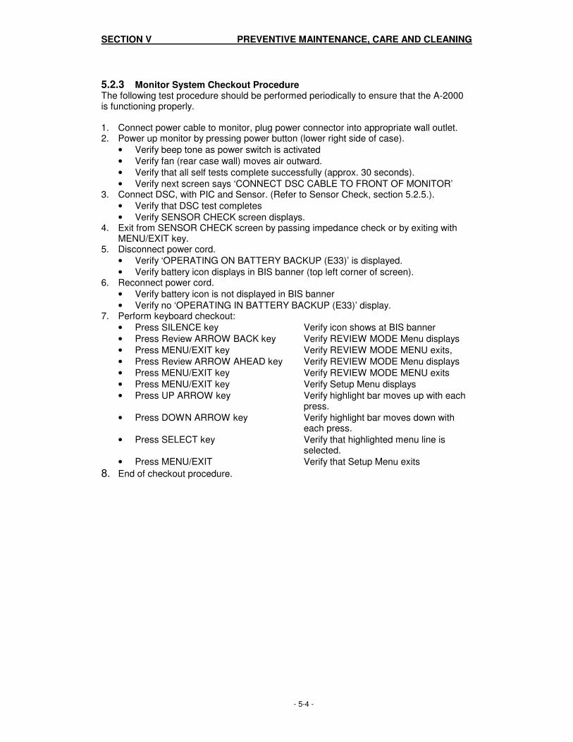
5.2.3 Monitor System Checkout Procedure The following test procedure should be performed periodically to ensure that the A-2000 is functioning properly. 1. Connect power cable to monitor, plug power connector into appropriate wall outlet. 2. Power up monitor by pressing power button (lower right side of case).
• Verify beep tone as power switch is activated
• Verify fan (rear case wall) moves air outward.
• Verify that all self tests complete successfully (approx. 30 seconds).
• Verify next screen says ‘CONNECT DSC CABLE TO FRONT OF MONITOR’ 3. Connect DSC, with PIC and Sensor. (Refer to Sensor Check, section 5.2.5.).
• Verify that DSC test completes
• Verify SENSOR CHECK screen displays. 4. Exit from SENSOR CHECK screen by passing impedance check or by exiting with
MENU/EXIT key. 5. Disconnect power cord.
• Verify ‘OPERATING ON BATTERY BACKUP (E33)’ is displayed.
• Verify battery icon displays in BIS banner (top left corner of screen). 6. Reconnect power cord.
• Verify battery icon is not displayed in BIS banner
• Verify no ‘OPERATING IN BATTERY BACKUP (E33)’ display. 7. Perform keyboard checkout:
• Press SILENCE key Verify icon shows at BIS banner
• Press Review ARROW BACK key Verify REVIEW MODE Menu displays
• Press MENU/EXIT key Verify REVIEW MODE MENU exits,
• Press Review ARROW AHEAD key Verify REVIEW MODE Menu displays
• Press MENU/EXIT key Verify REVIEW MODE MENU exits
• Press MENU/EXIT key Verify Setup Menu displays
• Press UP ARROW key Verify highlight bar moves up with each press.
• Press DOWN ARROW key Verify highlight bar moves down with each press.
• Press SELECT key Verify that highlighted menu line is selected.
• Press MENU/EXIT Verify that Setup Menu exits
8. End of checkout procedure.

SECTION V PREVENTIVE MAINTENANCE, CARE AND CLEANING
- 5-5 -
5.2.4 DSC Checkout Procedure Periodically the DSC and associated cables and connectors should be inspected for physical damage. 1. Inspect the DSC case to ensure the plastic is not cracked or broken. 2. Inspect the gasket seal around the perimeter of the DSC to verify the physical
integrity of the seal. 3. Inspect the cables and strain relief mechanism. 4. Inspect the connector that plugs into the monitor for damage or poor strain relief. 5. Inspect Patient Interface Cables (PIC) for damage to cable or connectors.
6. Perform DSC Self Test. See section 6.2.3.1.
5.2.5 Patient Interface Cable (PIC) Checkout Procedure The sensor check can be done using a Sensor Simulator (P/N 186-0105), following the instructions in Appendix 9.2. If a simulator is not available, use the following procedure to make a test sensor: 1. Remove a new sensor from its plastic carrier sheet and place on flat surface with the
adhesive facing up.
Note: Be careful that gel does not leak onto hands or connector during this procedure.
2. Place the end of a small paper clip at the midpoint of electrode element 1 then lay it
across element 2. (Elements 1 and 2 are the two closest together.) 3. Fold electrode element 3 over onto electrode 2, pressing adhesive surfaces together
and making sure the paper clip remains in place. 4. Fold electrode 1 over on itself, securing the other end of the paper clip and pressing
adhesive surfaces together. If necessary, secure it in place by wrapping a piece of tape around the outside.
5. Connect this test sensor to the sensor PIC. All impedance tests should complete successfully, with low impedance values. Typical values using this alternative test sensor are less than 5 Kohms.

SECTION V PREVENTIVE MAINTENANCE, CARE AND CLEANING
- 5-6 -

SECTION VI DIAGNOSTICS AND TROUBLESHOOTING
- 6-1 -
SECTION VI
6. DIAGNOSTICS AND TROUBLESHOOTING
INTRODUCTION This section explains:
• General troubleshooting
• The A-2000 power-up, automatic and manual diagnostic procedures
• Failure messages, causes, and corrective actions
• Diagnostic codes and their meanings
6.1 GENERAL TROUBLESHOOTING Using Table 6.1, the technician can troubleshoot the A-2000 monitor by matching a symptom to the list of probable causes and recommended corrective procedures. The corrective procedures include replacing assemblies. Corrective actions are arranged according to probability of cause. Table 6.1 Troubleshooting the A-2000 Monitor Symptoms:
Causes:
Corrective Procedures:
No display, no fan ON/OFF switch is OFF
Press power button on right side of monitor
Battery drained, unit unplugged
Plug in unit, then press power button
Power supply defective
Replace power supply
No display, fan running
Main board defective Replace Main board
E/L display defective
Replace E/L display
No main display
Any
Reboot to run boot diagnostic
Main display cabling
Check cables
Display driver circuit defective
Replace Main board
Main board defective
Replace Main board

SECTION VI DIAGNOSTICS AND TROUBLESHOOTING
- 6-2 -
Table 6.1 CONTINUED
Symptoms:
Causes:
Corrective Procedures:
No speaker sound Alarms silenced
Enable alarms
Main board defective
Replace main board
Keypad inoperative
Cable disconnected or defective
Reconnect or replace cables
Keypad defective
Replace keypad
Main board defective
Replace main board
All keys inoperative
Main board defective Replace main board
Printer inoperative Printer out of paper
Replace printer paper
Printer off-line Place printer on-line
A-2000 in battery backup mode
Replace A/C line cord power
Printer defective
Replace printer
Main board defective Interconnect board defective
Replace main board Replace Interconnect board
DSC disconnected error message
DSC is disconnected
Connect DSC to the monitor
DSC wire connection within cable connector is defective
Replace DSC
DSC cable to monitor is defective
Replace DSC
DSC is defective
Replace DSC
Main board defective Replace main board
SECTION VI DIAGNOSTICS AND TROUBLESHOOTING
- 6-3 -
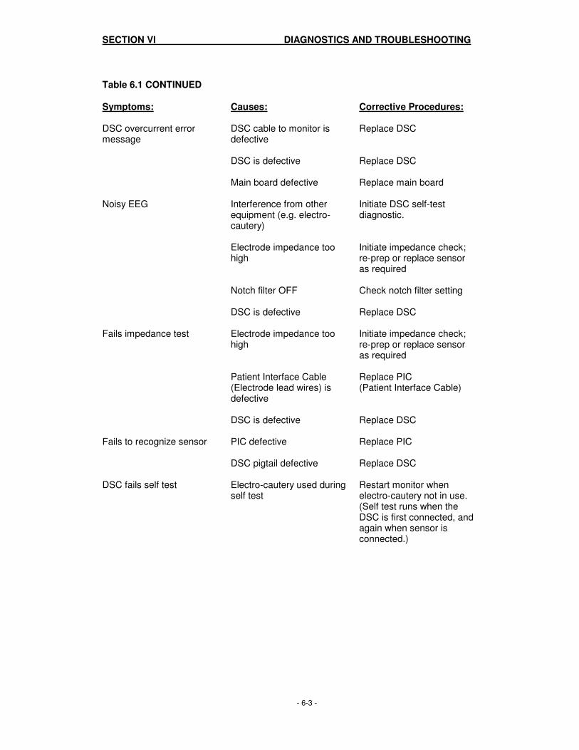
Table 6.1 CONTINUED
Symptoms: Causes: Corrective Procedures: DSC overcurrent error message
DSC cable to monitor is defective
Replace DSC
DSC is defective
Replace DSC
Main board defective Replace main board
Noisy EEG Interference from other equipment (e.g. electro-cautery)
Initiate DSC self-test diagnostic.
Electrode impedance too high
Initiate impedance check; re-prep or replace sensor as required
Notch filter OFF
Check notch filter setting
DSC is defective
Replace DSC
Fails impedance test Electrode impedance too high
Initiate impedance check; re-prep or replace sensor as required
Patient Interface Cable (Electrode lead wires) is defective
Replace PIC (Patient Interface Cable)
DSC is defective
Replace DSC
Fails to recognize sensor PIC defective Replace PIC
DSC pigtail defective Replace DSC
DSC fails self test Electro-cautery used during self test
Restart monitor when electro-cautery not in use. (Self test runs when the DSC is first connected, and again when sensor is connected.)
SECTION VI DIAGNOSTICS AND TROUBLESHOOTING
- 6-4 -
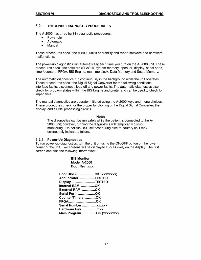
6.2 THE A-2000 DIAGNOSTIC PROCEDURES The A-2000 has three built-in diagnostic procedures:
• Power-Up
• Automatic
• Manual These procedures check the A-2000 unit’s operability and report software and hardware malfunctions. The power-up diagnostics run automatically each time you turn on the A-2000 unit. These procedures check the software (FLASH), system memory, speaker, display, serial ports, timer/counters, FPGA, BIS Engine, real-time clock, Data Memory and Setup Memory. The automatic diagnostics run continuously in the background while the unit operates. These procedures check the Digital Signal Converter for the following conditions: interface faults, disconnect, lead off and power faults. The automatic diagnostics also check for problem states within the BIS Engine and printer and can be used to check for impedance. The manual diagnostics are operator initiated using the A-2000 keys and menu choices. These procedures check for the proper functioning of the Digital Signal Converter, the display, and all BIS processing circuits.
Note: The diagnostics can be run safely while the patient is connected to the A-2000 unit; however, running the diagnostics will temporarily disrupt monitoring. Do not run DSC self test during electro-cautery as it may erroneously indicate a failure.
6.2.1 Power-Up Diagnostics To run power-up diagnostics, turn the unit on using the ON/OFF button on the lower corner of the unit. Two screens will be displayed successively on the display. The first screen contains the following information:
BIS Monitor Model A-2000 Boot Rev. x.xx
Boot Block .................. OK (xxxxxxxx) Annunciator..................TESTED Display ...................…...TESTED Internal RAM ...............OK External RAM ..............OK Serial Port ..............….OK Counter/Timers ........…OK FPGA........................…...OK Serial Number ............…xxxxxx Hardware Rev ............…x.xx Main Program ............…OK (xxxxxxxx)

SECTION VI DIAGNOSTICS AND TROUBLESHOOTING
- 6-5 -
The second screen contains the following information: BIS Monitor Model A-2000 System Rev. x.xx
Host Rev. .................…..x.xx Printer Port...............…..OK Diagnostic Port..............OK FPGA Rev..................…..x.xx FPGA ......................…….OK BIS Engine Rev. ............x.xx BIS Engine ..............….OK Real-Time Clock ............OK Data Memory ................. OK Setup Memory ................OK
In addition to these two screens, the A-2000 also uses audible tones to signal fatal errors. These are especially useful if a hardware failure prevents the display from working. Each audible error code consists of a long tone followed by one or more short tones, and finally another long tone. The specific error condition is indicated by the number of short tones: Table 6.2 Summary of Error Conditions
Error Condition # of short tones in beep code
FLASH Boot Block Failed Checksum 1 Main Program Checksum Check Failed 2 Software Update Serial Comm. Error 3 Software Update FLASH Error 4 Counter/Timer Test Failed 5 FPGA Init/Test Failed 6 Serial Port UART Loopback Failed 7 Host External RAM Failed 8 Host Internal RAM Failed 9

SECTION VI DIAGNOSTICS AND TROUBLESHOOTING
- 6-6 -
MESSAGES, CAUSES AND CORRECTIVE ACTIONS The power-up diagnostics identify a number of problems involving the A-2000’s software and hardware. Table 6.3 shows the messages associated with these diagnostics as well as the cause of the failure and the corrective action to take. Messages are arranged and listed in the following categories: RAM, program memory, I/O devices, BIS Engine, real-time clock, data memory, and setup memory. Corrective actions are arranged according to probability of cause. Table 6.3 Power-Up Failure Messages, Causes and Corrective Actions Failure Messages: Causes: Corrective Actions: RAM Checks: 8 short tones (no display) Host DRAM failure. Replace main board.
9 short tones (no display) Host SRAM failure. Replace main board.
Program Memory Checks: 1 short tone (no display) Bad checksum or signature
in Boot Block
Replace main board.
Main Program............FAILED (2 short tones)
Bad checksum or signature in Main Code area.
1. Reload Main Code again. 2. Replace main board.
I/O Device Checks: Serial Port..................FAILED (7 short tones)
Serial Port UART failed loopback test or interrupt test.
Replace main board
Counter/Timers.......FAILED (5 short tones)
Counter/timer(s) in Host processor failed.
Replace main board.
FPGA......................FAILED (6 short tones)
FPGA failed download or test.
1. Reload boot code and/or main code again. 2. Replace main board.
Printer Port.................FAILED
Printer Port UART failed loopback test or interrupt test.
Replace main board.
Diagnostic Port..........FAILED
Diagnostic Port UART failed loopback test or interrupt test.
Replace main board.

SECTION VI DIAGNOSTICS AND TROUBLESHOOTING
- 6-7 -
Table 6.3 Power-Up Failure Messages, Causes and Corrective Actions (CONTINUED) Failure Messages: Causes: Corrective Actions:
BIS Engine Initialization: BIS Engine.................FAILED
Problem with BIS Engine on main board.
Replace main board.
Real-Time Clock Checks: Real-Time Clock........FAILED SYSTEM HALTED
Real-time clock failed RAM test.
Replace main board.
Real-Time Clock......ERASED RTC TIME/DATE LOST
Time/date was corrupted in real-time clock.
1. Set time/date. 2. Check real-time clock battery.
Real-Time Clock......ERASED RTC RAM DATA LOST
RAM was corrupted in real-time clock.
Check real-time clock battery.
Data Memory: Data Memory.............FAILED SYSTEM HALTED
Data Memory failed erase or write.
Replace main board.
Data Memory............ERASED DATA MEMORY LOST Check Time/Date Test Clock Battery
Data Memory, or its control structure in the real-time clock RAM, is corrupted.
1. Check time/date. 2. Check real-time clock battery. 3. Replace main board.
Setup Memory: Setup Memory...........FAILED SETUP MEMORY LOST Default settings in effect
Setup Memory failed erase or write.
1. Check setup. 2. Replace main board.
Setup Memory..........ERASED SETUP MEMORY LOST Default settings in effect
Setup Memory was corrupted.
Check setup.
Setup Memory..........ERASED NEW SYSTEM SOFTWARE REVISION Setup Memory invalid Default settings in effect
Main code has been updated.
Check setup.
SECTION VI DIAGNOSTICS AND TROUBLESHOOTING
- 6-8 -
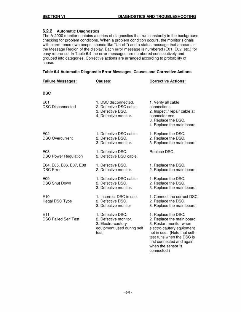
6.2.2 Automatic Diagnostics The A-2000 monitor contains a series of diagnostics that run constantly in the background checking for problem conditions. When a problem condition occurs, the monitor signals with alarm tones (two beeps, sounds like “Uh-oh”) and a status message that appears in the Message Region of the display. Each error message is numbered (E01, E02, etc.) for easy reference. In Table 6.4 the error messages are numbered consecutively and grouped into categories. Corrective actions are arranged according to probability of cause. Table 6.4 Automatic Diagnostic Error Messages, Causes and Corrective Actions Failure Messages: Causes: Corrective Actions:
DSC E01 DSC Disconnected
1. DSC disconnected. 2. Defective DSC cable. 3. Defective DSC. 4. Defective monitor.
1. Verify all cable connections. 2. Inspect / repair cable at connector end. 3. Replace the DSC. 4. Replace the main board.
E02 DSC Overcurrent
1. Defective DSC cable. 2. Defective DSC. 3. Defective monitor.
1. Replace the DSC. 2. Replace the DSC. 3. Replace the main board.
E03 DSC Power Regulation
1. Defective DSC. 2. Defective DSC cable.
Replace DSC.
E04, E05, E06, E07, E08 DSC Error
1. Defective DSC. 2. Defective monitor.
1. Replace the DSC. 2. Replace the main board.
E09 DSC Shut Down
1. Defective DSC cable. 2. Defective DSC. 3. Defective monitor.
1. Replace the DSC. 2. Replace the DSC. 3. Replace the main board.
E10 Illegal DSC Type
1. Incorrect DSC in use. 2. Defective DSC. 3. Defective monitor
1. Connect the correct DSC. 2. Replace the DSC. 3. Replace the main board.
E11 DSC Failed Self Test
1. Defective DSC. 2. Defective monitor. 3. Electro-cautery equipment used during self test.
1. Replace the DSC. 2. Replace the main board. 3. Restart monitor when electro-cautery equipment not in use. (Note that self-test runs when the DSC is first connected and again when the sensor is connected.)

SECTION VI DIAGNOSTICS AND TROUBLESHOOTING
- 6-9 -
Table 6.4 Automatic Diagnostic Error Messages, Causes and Corrective Actions (CONTINUED) Failure Messages: Causes: Corrective Actions: Sensor E12 Illegal Sensor Type
1. Defective Sensor. 2. Defective PIC. 3. Defective DSC. 4. Defective monitor.
1. Replace the Sensor. 2. Replace the PIC. 3. Replace the DSC. 4. Replace the main board.
E13, E15 Re-prep Sensor
1. Poor sensor connections. 2. Sensor impedance too high. 3. Defective Patient Interface Cable (PIC).
1. Check sensor connections. 2. Re-prep / replace sensor. 3. Replace the PIC.
E14 Sensor Not Connected
1. Disconnected Sensor 2. Disconnected PIC. 3. Defective PIC. 4. Defective DSC. 5. Defective monitor.
1. Connect the Sensor 2. Connect the PIC. 3. Replace the PIC. 4. Replace the DSC. 5. Replace the main board.
E16 Last Sensor Check Failed
1. At least one electrode has too high impedance. 2. Poor lead connection. 3. Defective PIC. 4. Defective DSC. 5. EXIT pressed prematurely.
1. Check impedance, re-prep/ replace electrodes. 2. Check lead connections. 3. Replace the PIC. 4. Replace the DSC. 5. Repeat check electrode test.
BIS Engine
E17, E19, E20, E21, E22, E23, E24 BIS Engine Comm. Error
Error in communication between BIS Engine and Host.
1. Update the software. 2. Replace the main board.
E18 BIS Engine Not Functional
Fatal BIS Engine error detected.
1. Turn monitor off, then on again. 2. Update the software. 3. Replace the main board.
E45 No Updates from BIS Engine
No data received from BIS Engine in last 15 seconds.
1. Turn monitor off, then on again. 2. Update the software. 3. Replace main board.
E46 BIS Engine Not Responding
BIS Engine has not responded to a command within 12 seconds.
1. Turn monitor off, then on again. 2. Update the software. 3. Replace main board.

SECTION VI DIAGNOSTICS AND TROUBLESHOOTING
- 6-10 -
Table 6.4 Automatic Diagnostic Error Messages, Causes and Corrective Actions (CONTINUED) Failure Messages: Causes: Corrective Actions: EEG Signal E25 Left Side SQI Bad
With 2-channel montage, left side signal quality is bad.
1. Re-prep the Sensor. 2. Check impedances.
E26 Right Side SQI Bad
With 2-channel montage, right side signal quality is bad.
1. Re-prep the Sensor. 2. Check impedances.
E27 Poor Signal Quality
The Signal Quality Index is less than 50% and the numeric display becomes “hollow”. This may occur as the result of artifact such as those generated from motion or the presence of electrocautery devices.
1. Re-prep the Sensor. 2. Check impedances.
E28 Bad Signal Quality
The Signal Quality Index is unacceptable. The Primary Trend variable cannot be calculated and therefore the numeric display is blanked. This may occur as the result of artifact such as those generated from motion or the presence of electrocautery devices.
1. Re-prep the Sensor. 2. Check impedances.
E29 BIS < Low Alarm Limit
The BIS has fallen below the low alarm limit set by the user. The numeric display flashes.
E30 BIS > High Alarm Limit
The BIS has risen above the high alarm limit set by the user. The numeric display flashes.
E31 Isoelectric EEG Detected
No discernible EEG activity is detected for several minutes; SR = 100.
1. Check the patient. 2. Check leads for proper connection and possible shorts.

SECTION VI DIAGNOSTICS AND TROUBLESHOOTING
- 6-11 -
Table 6.4 Automatic Diagnostic Error Messages, Causes and Corrective Actions (CONTINUED) Failure Messages: Causes: Corrective Actions: Battery
E33 Operating On Battery Backup
The AC power has been lost and the monitor is running on the battery. The battery keeps the monitor operating for approximately 20 minutes.
Restore the AC power.
E34 Battery Power Low
There are only a few minutes of battery life left.
Restore AC power to avoid automatic shutdown.
Software
E35 - E39, E43 - E45, E48 - E65 Software Error
A serious software error has occurred. The monitor may stop operating.
1. Turn the monitor off, then on again. 2. Update the software.
Memory E40 Setup Memory Write Error
Error in erasing or writing Setup block of FLASH memory.
1. Check Setup. 2. Replace main board.
E41 Real-Time Clock Write Error
Error in writing to Real-Time Clock RAM.
Replace main board.
E42 Can’t Save Setup
Monitor is unable to write to Setup Memory when battery power is low.
1. Restore AC power. 2. Save settings again.
E47 Data Memory Write Error
Error in erasing or writing Data Memory portion of FLASH memory.
Replace main board.

SECTION VI DIAGNOSTICS AND TROUBLESHOOTING
- 6-12 -
Table 6.4 Automatic Diagnostic Error Messages, Causes and Corrective Actions (CONTINUED) Failure Messages: Causes: Corrective Actions: Printer
E66 Printer Out of Paper
Printer is out of paper.
Replace the paper.
E67 Printer Error
1. Printer is off-line. 2. Print head is up. 3. Printer is disconnected. 4. Print head temperature out of range. 5. Print head voltages out of range. 6. Printer hardware failure.
1. Put printer on-line. 2. Close print head. 3. Connect printer. 4. Replace printer.

SECTION VI DIAGNOSTICS AND TROUBLESHOOTING
- 6-13 -
6.2.3 Manual Diagnostics Diagnostic tests may be initiated by selecting them from the Diagnostic Menu. 1. Press the [MENU/EXIT] key from the Main Screen to access the Setup menu. 2. Highlight Advanced Setup using the [▲] or [▼] key, then press [SELECT]. 3. Highlight the Diagnostic Menu, then press [SELECT]. The Diagnostic Menu
appears. 4. Select the desired option from this menu: Select: To: DSC Self Test Run the DSC self test diagnostics. Display Self Test Run the EL Display self test diagnostic. Diagnostics Codes ON Display diagnostics codes in the Message Region of the screen. 6.2.3.1 DSC Self Test The DSC self test is a thorough test of the entire signal processing chain including the signal processing computers. Selecting this item will initiate an extensive DSC test and a printer test (if one is connected). Do not run this test while electro-cautery equipment is in use. To begin the test: 1. Highlight DSC Self Test, then press [SELECT]. The DSC testing screen will display. 2. The following information appears: DSC Test Results: In Progress Ch1 Ch2 Noise (µV) * * * * * * Hi-Pass Blocked (µV) * * * * * * Hi-Pass Normal (µV) * * * * * * Gain (µV) * * * * * * The DSC test consists of four sub-tests. The first checks the noise, the second checks the high-pass filter performance with the amplifiers blocked (fast response), the third checks the high-pass filter performance with the amplifiers unblocked (high bandwidth), and the fourth checks the amplifier gains. The results of each of these sub-tests are displayed for each of the two channels. If any result is outside the allowed range, the number has an asterisk appended to it. The allowed range for each of the sub-tests are: Noise: 0 - 0.24 (µV) Hi-Pass Blocked: 47.1 - 63.9 (µV) Hi-Pass Normal: 14.7 - 18.5 (µV) Gain: 49.2 - 60.2 (µV) If the Digital Signal Converter is properly connected, the ‘***’ symbols displayed for each test parameter will change to numeric values for the corresponding channel. “DSC Test Results: PASS (or FAIL*)” message will appear at the end of test. If test fails, check the connection between the DSC and the monitor, make certain that electro-cautery equipment is not in use, and run DSC self test again. If the DSC test fails again, the DSC requires service.

SECTION VI DIAGNOSTICS AND TROUBLESHOOTING
- 6-14 -
6.2.3.2 Display Self Test To initiate a test of the screen display, highlight Display Self Test and press [SELECT]. The following screen is displayed: Press SELECT to start test. Press MENU/EXIT to end test. When [SELECT] is pressed, the display will start to cycle through 3 test screens: a) All pixels on. b) Alternating pixels on (checkerboard). c) Reverse of b). The test will randomly start in one of these three screens. Each screen lasts for about 7 seconds. Press [MENU/EXIT] to end the test and return to the Diagnostic Menu.
Note: Display Self Test will not run in Battery Mode.

SECTION VI DIAGNOSTICS AND TROUBLESHOOTING
- 6-15 -
6.2.3.3 Using the Diagnostic Codes If you are experiencing problems with the A-2000 system, you may wish to turn the Diagnostic Codes ON so that numerical diagnostic values will be displayed in the message region of the screen. This feature is intended for qualified service personnel. Refer to Table 6.5 for a description of the codes. To turn the codes on, highlight the Diagnostic Codes line, use the [SELECT] key to reverse-highlight “ON”, then press MENU/EXIT to exit. Table 6.5 Diagnostic Codes and their Meanings
Bit Display Code Description Code Meaning
0 00000001 Flatline Spectrum
1 00000002 Out Of Range (validation only)
2 00000004 Bad Slope (Slew Rate) Slew rate too high
3 00000008 Pacer/EKG Detected EKG or Pacer artifact detected
4 00000010 Throw Away Still recovering from previous artifact
5 00000020 Burst Suppressed Suppression detected (the standard deviation for the entire second is below a minimum value.)
6 00000040 Start-Up FPU starting up, does not have full epoch yet.
7 00000080 (not used)
8 00000100 Total Power Too Small
9 00000200 Motion (Sudden Change) Low frequency or eye blink artifact detected.
10 00000400 Glitch (High Frequency) High frequency artifact detected.
11 00000800 Leadoff Clip Negative The signal for the minus lead has been clipping in the same direction for 3 seconds continuously.
12 00001000 Leadoff Clip Positive The signal for the plus lead has been clipping in the same direction for 3 seconds continuously
13 00002000 Combined Impedance Too High
Combined electrode impedance measures greater than 20K Ohms
14 00004000 (not used)
15 00008000 Clipping Raw EEG data out of range during last second.
16 00010000 DSC Framing Error Indicates that at least one frame of data from the DSC was bad in the last second.
17 00020000 DSC Busy Error DSC could not receive commands during the last second.
18 00040000 No DSC Interrupt DSC is not interrupting the IPU. The DSC interrupt should occur at a 16 KHz rate.
19 00080000 DSC Interface Fault Interface between the DSC and main board is malfunctioning.
20 00100000 DSC Power Regulation Voltage regulators on the DSC are malfunctioning.
21 00200000 (not used)
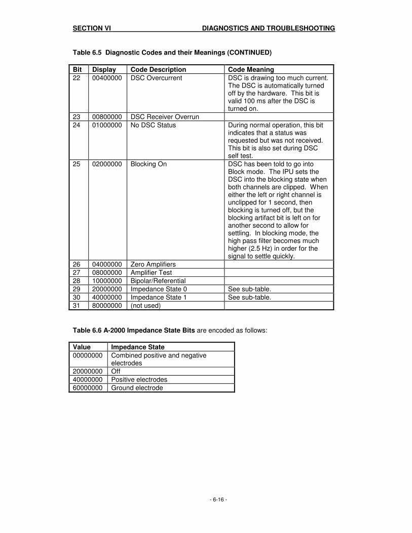
SECTION VI DIAGNOSTICS AND TROUBLESHOOTING
- 6-16 -
Table 6.5 Diagnostic Codes and their Meanings (CONTINUED)
Bit Display Code Description Code Meaning
22 00400000 DSC Overcurrent DSC is drawing too much current. The DSC is automatically turned off by the hardware. This bit is valid 100 ms after the DSC is turned on.
23 00800000 DSC Receiver Overrun
24 01000000 No DSC Status During normal operation, this bit indicates that a status was requested but was not received. This bit is also set during DSC self test.
25 02000000 Blocking On DSC has been told to go into Block mode. The IPU sets the DSC into the blocking state when both channels are clipped. When either the left or right channel is unclipped for 1 second, then blocking is turned off, but the blocking artifact bit is left on for another second to allow for settling. In blocking mode, the high pass filter becomes much higher (2.5 Hz) in order for the signal to settle quickly.
26 04000000 Zero Amplifiers
27 08000000 Amplifier Test
28 10000000 Bipolar/Referential
29 20000000 Impedance State 0 See sub-table.
30 40000000 Impedance State 1 See sub-table.
31 80000000 (not used)
Table 6.6 A-2000 Impedance State Bits are encoded as follows:
Value Impedance State
00000000 Combined positive and negative electrodes
20000000 Off
40000000 Positive electrodes
60000000 Ground electrode

SECTION VI DIAGNOSTICS AND TROUBLESHOOTING
- 6-17 -
6.2.3.4 Impedance Checking The A-2000 continually checks impedance levels during a procedure by generating a 128 Hz test signal. Occasionally this signal may interfere with other equipment. If this becomes a problem, you may turn off the continuous impedance checking in the Diagnostic Menu. 1. Highlight “Impedance Checking”, then press the [SELECT] key until “OFF” appears in
reverse video. 2. Use the arrows to go to the next option, or press [MENU/EXIT] to exit. Impedance
levels will still be tested at start up, but once they pass, they will not be tested again until a new case is begun.
Note:
Turning off continuous impedance checking will not be saved by the “Save Current Settings” feature. The next time the monitor is powered on, the monitor will re-enable continuous impedance checking.

SECTION VI DIAGNOSTICS AND TROUBLESHOOTING
- 6-18 -

SECTION VII DISASSEMBLING AND REASSEMBLING THE A-2000™
- 7-1 -
SECTION VII
7. DISASSEMBLING AND REASSEMBLING THE A-2000
INTRODUCTION This section provides instructions for removing and replacing parts within the A-2000 monitor unit.
Note: The Digital Signal Converter (DSC) is sealed; there are no serviceable parts inside. In the event of a DSC malfunction, contact Aspect Medical Systems or your authorized service representative for a replacement.
WARNING:
ANY PROCEDURES THAT REQUIRE THE REMOVAL OF THE MONITOR’S COVER AND INTERNAL PARTS SHOULD BE PERFORMED BY A QUALIFIED BIOMEDICAL ENGINEERING TECHNICIAN. POWER OFF THE UNIT USING THE POWER SWITCH. UNPLUG THE MONITOR BEFORE DISASSEMBLING/ REASSEMBLING THE A-2000. IF METAL COMES IN CONTACT WITH THE TERMINALS ON THE BATTERY, IT COULD RESULT IN PERMANENT DAMAGE TO THE BATTERY AND IS AN ELECTRICAL SHOCK HAZARD. DUE TO THE BATTERY OPERATION POSSIBLE WITH NO AC CONNECTED, EXTREME CARE MUST BE USED WHEN DISASSEMBLING AND ASSEMBLING THE A-2000 MONITOR. WITH AC DISCONNECTED AND BATTERY POWER ON, HIGH VOLTAGE IS PRESENT ON THE E/L DISPLAY AND POWER SUPPLY PCB. DO NOT ACTIVATE POWER ON SWITCH WITH CASE OPEN! GROUND WIRE LEAKAGE CURRENT MUST BE CHECKED BY A QUALIFIED BIOMEDICAL ENGINEERING TECHNICIAN WHENEVER THE INSTRUMENT CASE IS OPENED FOR INSPECTION OR SERVICE.

SECTION VII DISASSEMBLING AND REASSEMBLING THE A-2000™
- 7-2 -
7.1 REQUIRED TOOLS AND SUPPLIES Table 7.1 Tools and Supplies to Assemble/ Disassemble the A-2000 Monitor
Tool or Supply:
Required for:
#1 phillips screwdriver #2 phillips screwdriver
Removing the monitor cover screws, bezel screws, the electro-luminescent display panel, main board assembly, power supply, battery, and fan
7/16” nut driver or wrench Detaching the ground stud.
Small, flat blade screwdriver
Removing the switch set, removing the Interconnect PCB and Main board
Needle-nose pliers
Stripping off the switch set, releasing standoff tabs to separate boards
Wire cutter
Cutting cable ties used to anchor battery.
Wrench for special connector nut #820-0002
Removing the DSC connector nut.
Lint free cloth
Cleaning the E/L screen
Isopropyl alcohol
Removing residue
Cable ties
Reassembling the battery.
Blue tape # 726-0006 Attaching the E/L display cable
Double sided tape # 725-0005 Installing shield on Power Supply PCB See section 7.7.
Loctite 425 # 705-0010 Installing case and clamp shoe screws
Hex wrench 3/32 inch Pole clamp Allen screw
Copper tape 725-0005 EMC connection
Caution: Use only the parts and tools specified. Use of any others may damage the instrument.

SECTION VII DISASSEMBLING AND REASSEMBLING THE A-2000™
- 7-3 -
7.2 THE MONITOR CASE
7.2.1 Opening the Monitor Case
WARNING: DUE TO THE BATTERY OPERATION POSSIBLE WITH NO AC CONNECTED, EXTREME CARE MUST BE USED WHEN DISASSEMBLING AND ASSEMBLING THE A-2000 MONITOR. WITH AC DISCONNECTED AND BATTERY POWER ON, HIGH VOLTAGE IS PRESENT ON THE E/L DISPLAY AND POWER SUPPLY PCB. DO NOT ACTIVATE POWER ON SWITCH WITH CASE OPEN!
1. Unplug the AC line cord from the monitor. 2. Using special wrench (# 820-0002) remove the nut from the DSC cable connector on
the front of the bezel.
Caution: Use only the parts and tools specified. Use of any other may damage the instrument.
3. Remove the two screws from the top corners of the bezel. 4. Remove the two front feet screws from the bottom of the case. 5. With unit laying face down on a suitable no scratch work surface, separate and stand
up back section of case. DO NOT SEPARATE PIECES MORE THAN 1 INCH UNTIL CABLES ARE DISCONNECTED! (See Figure 7-1).
6. Remove tape and unplug the flat cable of the E/L display (larger of the two) from its socket on the main PCB. (See Figure 7-2). Take care to save the tape so that it can be used to re-attach the cable.
7. To remove the small flex circuit cable of the switch panel, gently pry up the tension flange on the connector at the Interconnect PCB, releasing the flex circuit cable. (See Figure 7-3).
8. The bezel and case are now separated to allow further service action.
7.2.2 Closing the Monitor Case Refer to Figures 7-1 through 7-3. 1. Reconnect the flex circuit cable from the switch panel to the connector on the
Interconnect PCB. Lift the tension flange, carefully insert the flex circuit, and then gently press the tension flange down to secure the connection.
2. Plug the E/L display cable into its connector on the Main PCB and secure with tape. Take care to make sure the cable bends upward when closing the case assembly.
3. If the power button cap has been removed, align it so that the 0 faces rear of monitor.
WARNING: DUE TO THE BATTERY OPERATION POSSIBLE WITH NO AC CONNECTED, EXTREME CARE MUST BE USED WHEN DISASSEMBLING AND ASSEMBLING THE A-2000 MONITOR. WITH AC DISCONNECTED AND BATTERY POWER ON, HIGH VOLTAGE IS PRESENT ON THE E/L DISPLAY AND POWER SUPPLY PCB. DO NOT ACTIVATE POWER ON SWITCH WITH CASE OPEN!
4. Carefully place the bezel and rear case together, assuring that the power button cap
is fully into its recess, and no cables are trapped at the joint. 5. Install the two screws into the top corners of the bezel; do not tighten.

SECTION VII DISASSEMBLING AND REASSEMBLING THE A-2000™
- 7-4 -
6. Using Loctite 425, install 2 rubber feet and screws into the bottom of the monitor. Do not tighten.
Caution: VERY IMPORTANT! Use only the Loctite number specified. Using the incorrect Loctite will damage plastic components.
7. Install the nut on the DSC connector using the special wrench (#820-0002). 8. Tighten all screws and the connector nut. Reconnect the power cord. 9. Check continuity for less than 10 Ohms between chassis ground lug on rear of
monitor and pin # 5 of the DSC connector on front panel of monitor. (Refer to section 8.2.5. for pin-out information.) If the continuity is greater than 10 Ohms, the grounding connection between the Interconnect PC board L bracket and inner case (secured by nylon screw) must be checked.
Note:
Failure to check continuity may result in excess electro-magnetic radiation from the DSC monitor interface cable. However, this check need not be done unless the Main Board PCB or Interconnect PCB assembly has been removed.

SECTION VII DISASSEMBLING AND REASSEMBLING THE A-2000™
- 7-5 -
Figure 7-1 Opening the Monitor Case
Tape
Figure 7-2 The E/L Display Cable
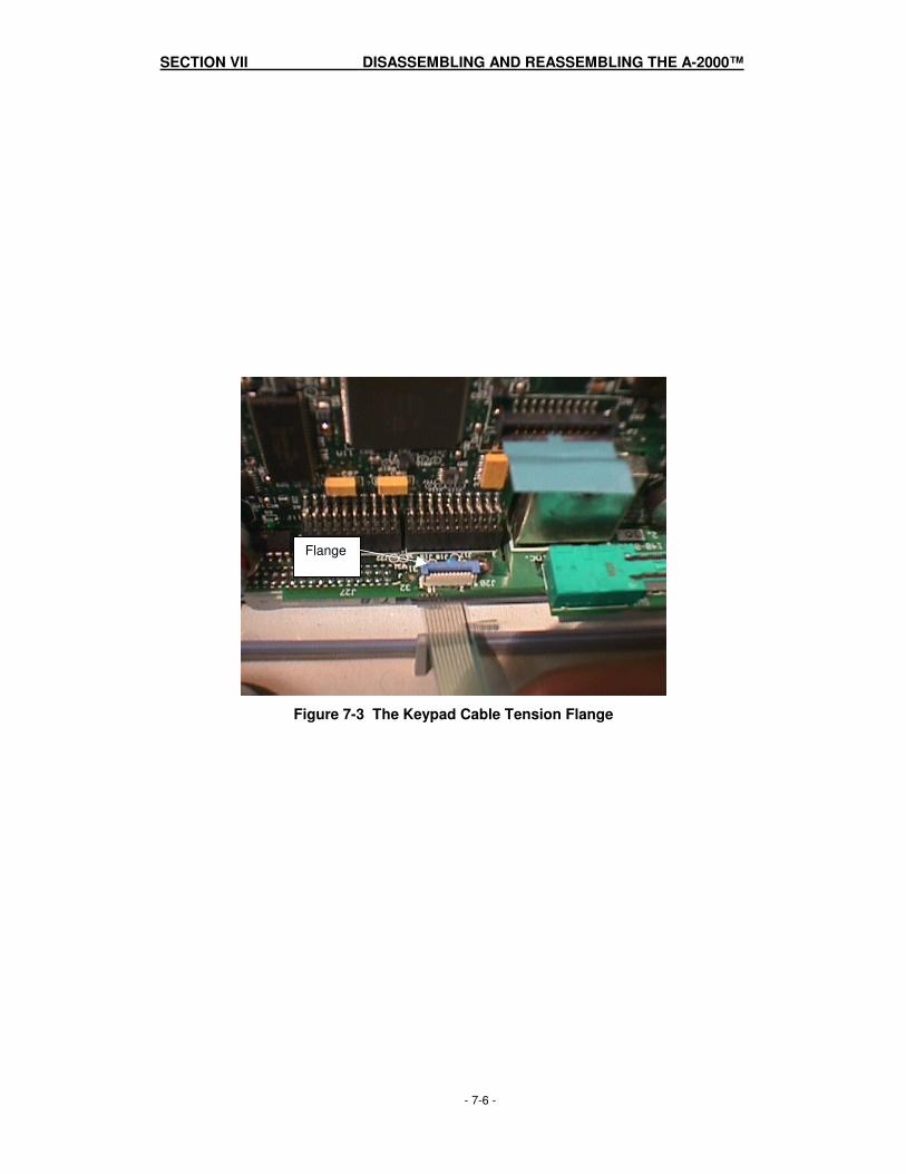
SECTION VII DISASSEMBLING AND REASSEMBLING THE A-2000™
- 7-6 -
Flange
Figure 7-3 The Keypad Cable Tension Flange

SECTION VII DISASSEMBLING AND REASSEMBLING THE A-2000™
- 7-7 -
7.3 THE ELECTRO/LUMINESCENT DISPLAY
7.3.1 Removing the E/L Display Board 1. With bezel assembly dismounted from case (see section 7.2.1), remove the four
mounting screws. (See Figure 7-4). 2. Pull the board free, leaving the gasket in place.
7.3.2 Reattaching the E/L Display Board 1. Carefully position the gasket in the gasket groove with gap located at the top. 2. Place the E/L display board into position, trapping the gasket. 3. Replace the four mounting screws loosely. 4. Align the PCB and verify that the gasket has not shifted (ensure that it is not visible
from screen side). 5. Tighten the mounting screws. 6. Reassemble bezel to case as described in section 7.2.2.
Caution: Failure to position E/L Display screen gasket properly may result in a monitor that will allow fluid to leak in when the display is cleaned.

SECTION VII DISASSEMBLING AND REASSEMBLING THE A-2000™
- 7-8 -
Figure 7-4 The Four Mounting Screws
SECTION VII DISASSEMBLING AND REASSEMBLING THE A-2000™
- 7-9 -
7.4 THE FRONT PANEL SWITCH SET The switch set is not serviceable and should not be removed unless a new one is to be installed. Removing the switch set will destroy it.
7.4.1 Removing the Switch Set 1. With bezel assembly dismounted from case (see Section 7.2.1), remove EMI strip.
(See Figure 7-5). 2. Insert flat blade screwdriver through the cable access port to push switch set panel
away from bezel. (See Figure 7-5). 3. From front panel, carefully peel rubberized surface of switch set from bezel assembly. 4. Pull flex circuit cable and EMI strip through access port and discard switch set. 5. Using isopropyl alcohol and a cloth, remove any residue remaining on bezel surface.
Allow surface to dry completely before installing new switch set.
7.4.2 Installing the New Switch Set 1. Remove the covering on the back of the new switch set, exposing the adhesive. (See
Figure 7-6). 2. Feed the switch set flex circuit cable and EMI strip through the access port in the
bezel. 3. Position the set carefully along an edge and press down to secure it to the bezel
surface. Press securely over entire surface to assure complete adhesion. 4. Turn bezel over and secure the EMI strip to the metalized interior surface. 5. Reassemble bezel to case as described in Section 7.2.2.
Note: Failure to properly secure the Electro-magnetic Interference strip may result in excess Electro-magnetic radiation from the Switch Set.

SECTION VII DISASSEMBLING AND REASSEMBLING THE A-2000™
- 7-10 -
EMI strip
Figure 7-5 The Cable Access Port
Figure 7-6 Remove the covering on the back of the new switch set

SECTION VII DISASSEMBLING AND REASSEMBLING THE A-2000™
- 7-11 -
7.5 THE PRINTED CIRCUIT BOARD ASSEMBLY The Interconnect PCB and connected assemblies must be removed to gain access to the Main PCB, fan, battery, power supply, or rear case shell.
7.5.1 Removing the Printed Circuit Board assembly 1. With rear case assembly dismounted from bezel (see Section 7.2.1), place rear case
assembly face down on a scratch free work surface with bottom of case facing you. (See Figure 7-7).
2. From bottom surface remove right side rubber foot, steel flat head screw (center), and nylon flat head screw (right side).
3. From monitor rear surface remove ground stud (use 7/16 driver wrench), two screws from AC input module, and two screws from deep recess holes.
4. Carefully stand case upright, being careful to not damage cable attaching fan (case mounted) to Interconnect PCB. (See Figure 7-8).
5. Disconnect fan cable from Interconnect PCB. (Pry release tab away from connector.) Case is now free from the Printed Circuit Board Assembly. Be careful to not lose two case screws (in deep recess) or power switch cap.
6. Printed Circuit Board Assembly or rear case shell are now ready for further service activities.
7.5.2 Installing the Printed Circuit Board Assembly Refer to Figures 7-7, 7-8 and 7-21.
Note: On newer A-2000 units copper tape has been added to the inside of the monitor case to improve the ground connection. The tape improves the conductivity between the L bracket of the Interconnect PCB and the shielded coating of the inside of the case. If your unit does not have the tape, it is recommended that you install it as shown in Figure 7-21.
1. With the rear case sitting upright on its bottom surface, connect the fan cable to the
J30 Interconnect PCB connector (next to the battery). (See Figure 7-8). 2. If power switch cap has been removed, install it with the 0 on the button facing the
rear of the instrument. WARNING:
DUE TO THE BATTERY OPERATION POSSIBLE WITH NO AC CONNECTED, EXTREME CARE MUST BE USED WHEN DISASSEMBLING AND ASSEMBLING THE A-2000 MONITOR. WITH AC DISCONNECTED AND BATTERY POWER ON, HIGH VOLTAGE IS PRESENT ON THE E/L DISPLAY AND POWER SUPPLY PCB. DO NOT ACTIVATE POWER ON SWITCH WITH CASE OPEN!
3. Place the Printed Circuit Board Assembly carefully inside the case and hold against
back wall. 4. Install equipotential stud into rear case. Do not tighten. 5. Install the two screws into the deep recesses in rear case. Do not tighten.

SECTION VII DISASSEMBLING AND REASSEMBLING THE A-2000™
- 7-12 -
6. Loosen L bracket screw (Fig. 7-10). Be sure to check that the alignment of bottom
screws is adequate, then install rubber foot, flat head steel (in center position), and flat head nylon screw (right side). Tighten nylon screw first. Do not over-tighten nylon screw. Then tighten L bracket screw.
Note:
It is important to follow the instructions regarding the sequence of tightening the screws in step 6 above. Failure to do so may result in excess electro-magnetic radiation from the DSC monitor interface cable.
7. Install two screws at A/C input module. 8. Tighten all screws and equipotential stud. Do not over-tighten. 9. Close case using the instructions in Section 7.2.2.

SECTION VII DISASSEMBLING AND REASSEMBLING THE A-2000™
- 7-13 -
EquipotentialStud
Flat screw Nylon screw
Figure 7-7 Place rear case assembly face down on a scratch free work surface
Figure 7-8 Fan Cable

SECTION VII DISASSEMBLING AND REASSEMBLING THE A-2000™
- 7-14 -
7.6 THE MAIN PCB
7.6.1 Removing the Main PCB 1. Open the monitor case as described in Section 7.2.1. 2. Remove the Printed Circuit Board Assembly as described in Section 7.5.1. 3. To separate Main PCB from Interconnect assembly, release standoff tab by
squeezing with needle-nose pliers, while gently separating at standoff. Repeat for second standoff tab. (See Figure 7-9).
4. Remove L bracket by removing Phillips screw from under Interconnect PCB at Main PCB (marked J201). (See Figure 7-10). This step is not necessary for Rev 2 or higher Interconnect Board.
5. Holding Interconnect PCB in one hand and upper end of Main PCB in the other, gently flex and pull to separate PCBs. BE CAREFUL NOT TO BEND PINS ON INTERCONNECT PCB. (See Figure 7-11).
7.6.2 Installing the Main PCB Refer to Figures 7-9 through 7-14. 1. To connect Main PCB to Interconnect assembly, line up pins of Interconnect PCB to
socket of Main PCB and align key with Interconnect notch. (See Figure 7-12). Push gently until pins are seated. BE CAREFUL NOT TO BEND PINS ON INTERCONNECT PCB.
2. Align standoffs on top of Power Supply PCB with Main PCB holes and push in until standoff tabs snap into place. (See Figure 7-13).
3. Install L bracket by holding long side; short side connects to Main PCB at rear of J201. Secure with Phillips screw, using Loctite 425. (See Figures 7-14 and 7-15).
Caution:
VERY IMPORTANT! Use only the Loctite number specified. Using the incorrect Loctite will damage plastic components.
4. Install the Interconnect PCB w/ Components as described in section 7.5.2. 5. Close the monitor case as described in section 7.2.2.

SECTION VII DISASSEMBLING AND REASSEMBLING THE A-2000™
- 7-15 -
Figure 7-9 Release standoff tab by squeezing with needle-nose pliers
L bracket
Figure 7-10 The L bracket

SECTION VII DISASSEMBLING AND REASSEMBLING THE A-2000™
- 7-16 -
Interconnect PCB
Main PCB
Power Supply PCB
Figure 7-11 Gently pull and flex to separate PCBs
Interconnect PCB pins
Main PCB socket
Interconnect PCB Notch
Figure 7-12 Line up Interconnect PCB pins to Main PCB socket

SECTION VII DISASSEMBLING AND REASSEMBLING THE A-2000™
- 7-17 -
Figure 7-13 Align standoffs and push in until standoff tabs snap into place
Figure 7-14 Install L bracket by holding long side; short side connects to Main PCB

SECTION VII DISASSEMBLING AND REASSEMBLING THE A-2000™
- 7-18 -
L bracket
Figure 7-15 The L Bracket Installed

SECTION VII DISASSEMBLING AND REASSEMBLING THE A-2000™
- 7-19 -
7.7 THE POWER SUPPLY PCB
7.7.1 Removing the Power Supply PCB 1. Open the monitor case as described in Section 7.2.1. 2. Remove the Interconnect PCB as described in Section 7.5.1. 3. Disconnect battery cable from PCB by depressing securing tab and lifting connector
from J300 jack. (See Figure 7-19). 4. To separate Power Supply PCB from Main PCB, release standoff tab by squeezing
with needle-nose pliers, while gently separating at standoff. Repeat for second standoff tab. (See Figure 7-9).
5. Holding Interconnect PCB in one hand and upper end of Power Supply PCB in the other, gently flex and pull Power Supply PCB free of pins. BE CAREFUL NOT TO BEND PINS ON INTERCONNECT PCB. (See Figure 7-16).
6. Remove battery assembly by removing four screws on rear of Power Supply PCB. (See Figure 7-17)
7. Remove shield from rear of Power Supply PCB. (See Figure 7-18).
7.7.2 Installing the Power Supply PCB 1. Install shield using double sided tape (part number 725-0005), aligning battery
bracket holes. 2. Install battery assembly with cable toward connector PCB edge, using screws and flat
washers. (See Figure 7-17). 3. Replace Power Supply PCB by aligning pins and alignment key to Interconnect PCB,
gently pushing in until pins are seated. 4. Align standoffs at top of Power Supply PCB with holes of Main PCB and press
together until standoff tabs snap into place. 5. Reconnect battery cable to Power Supply PCB. (See Figure 7-19). 6. Install the Interconnect PCB w/ Components as described in section 7.5.2. 7. Close the monitor case as described in 7.2.2.

SECTION VII DISASSEMBLING AND REASSEMBLING THE A-2000™
- 7-20 -
Figure 7-16 Gently flex and pull Power Supply PCB free of pins
Figure 7-17 Remove four screws on rear of Power Supply PCB

SECTION VII DISASSEMBLING AND REASSEMBLING THE A-2000™
- 7-21 -
Figure 7-18 Remove shield from rear of Power Supply PCB

SECTION VII DISASSEMBLING AND REASSEMBLING THE A-2000™
- 7-22 -
7.8 THE BATTERY
7.8.1 Removing the Battery
WARNING: DUE TO THE BATTERY OPERATION POSSIBLE WITH NO AC CONNECTED, EXTREME CARE MUST BE USED WHEN DISASSEMBLING AND ASSEMBLING THE A-2000 MONITOR. WITH AC DISCONNECTED AND BATTERY POWER ON, HIGH VOLTAGE IS PRESENT ON THE E/L DISPLAY AND POWER SUPPLY PCB. DO NOT ACTIVATE POWER ON SWITCH WITH CASE OPEN!
WARNING: IF METAL COMES IN CONTACT WITH THE TERMINALS ON THE BATTERY, IT COULD RESULT IN PERMANENT DAMAGE TO THE BATTERY AND IS AN ELECTRICAL SHOCK HAZARD.
Caution: Used batteries must be recycled or disposed of properly. Contact Aspect Medical Systems or your local distributor for a replacement battery and instructions for returning the defective battery for proper recycling/disposal.
8. Open the monitor case as described in Section 7.2.1. 9. Remove the Interconnect PCB as described in Section 7.5.1. 10. Disconnect battery cable by depressing securing tab and lifting connector from J300
jack. (See Figure 7-19). 11. With power supply still connected to the Interconnect PCB, cut tie wraps holding
battery pack to its mount. 12. Remove battery and tie wrap remains.
7.8.2 Installing the Battery 1. Carefully route new tie wraps under battery holder. 2. Place new battery assembly in position (with cable positioned close to jack) and
secure to holder with tie wraps. Be sure tie wraps are positioned as shown in Fig. 7-19 to avoid interference with case when closing the case.
3. Reconnect battery cable to jack (J300 power supply PCB). 4. Install Interconnect PCB as described in section 7.5.2. 5. Close the monitor case as described in section 7.2.2.
Caution: Replace battery only with same type of approved battery. Use of non-approved battery may result in incorrect operation or damage to the monitor.

SECTION VII DISASSEMBLING AND REASSEMBLING THE A-2000™
- 7-23 -
Tie Wraps
J 300
Figure 7-19 Battery and cable
SECTION VII DISASSEMBLING AND REASSEMBLING THE A-2000™
- 7-24 -
7.9 THE FAN
7.9.1 Removing the Fan
WARNING: DUE TO THE BATTERY OPERATION POSSIBLE WITH NO AC CONNECTED, EXTREME CARE MUST BE USED WHEN DISASSEMBLING AND ASSEMBLING THE A-2000 MONITOR. WITH AC DISCONNECTED AND BATTERY POWER ON, HIGH VOLTAGE IS PRESENT ON THE E/L DISPLAY AND POWER SUPPLY PCB. DO NOT ACTIVATE POWER ON SWITCH WITH CASE OPEN!
1. Open the monitor case as described in Section 7.2.1. 2. Remove the Printed Circuit Board Assembly as described in Section 7.5.1. 3. Note wire orientation on installed fan (looking into case, wire exits fan upper left
quarter). (See Figure 7-20). 4. Remove four mounting screws. Retain fan gasket and soft washers.
Note: Newer versions of the A-2000 have only two mounting screws.
7.9.2 Installing the Fan 1. Position fan over gasket with correct wire exit orientation and airflow is out of case.
(See Figure 7-20). 2. Using Loctite 425, install four mounting screws with soft washers. (Only two screws
are used in newer versions of the A-2000. See Figure 7-21.) Carefully tighten screws without over-tightening.
Caution: VERY IMPORTANT! Use only the Loctite number specified. Using the incorrect Loctite will damage plastic components.
3. Install Interconnect PCB as described in section 7.5.2. 4. Close the monitor case as described in section 7.2.2.
WARNING: FAN WIRE MUST BE POSITIONED AS SHOWN IN FIG. 7-21. INCORRECT ROUTING OF FAN WIRE MAY RESULT IN A HAZAROUS CONDITION.

SECTION VII DISASSEMBLING AND REASSEMBLING THE A-2000™
- 7-25 -
Clamp ShoeScrews
Wiring
Fan MountingScrews (4)
Figure 7-20 Fan wiring orientation and Clamp Shoe screws
RubberBumper
Fan MountingScrews (2)
ConductiveCopper Tape
Figure 7-21 Updated System with 2 Fan Mounting screws and Copper Tape

SECTION VII DISASSEMBLING AND REASSEMBLING THE A-2000™
- 7-26 -
7.10 THE CLAMP SHOE ASSEMBLY
7.10.1 Removing the Clamp Shoe Assembly 1. Open the monitor case as described in Section 7.2.1. 2. Remove the Interconnect PCB as described in Section 7.5.1. 3. Remove three screws securing shoe clamp assembly. (See Figure 7-20).
7.10.2 Installing the Clamp Shoe Assembly 1. Install screws securing clamp shoe assembly using Loctite 425. 2. Install the Interconnect PCB w/ Components as described in 7.5.2. 3. Close the monitor case as described in section 7.2.2.
Caution: VERY IMPORTANT! Use only the Loctite number specified. Using the incorrect Loctite will damage plastic components.

SECTION VII DISASSEMBLING AND REASSEMBLING THE A-2000™
- 7-27 -
7.11 FUSE REPLACEMENT The A-2000 contains two inline fuses (1.25A, 250V, 5x20mm Aspect P/N 430-0006) within the AC power input module located at the rear of the monitor. In the unlikely event that a fuse needs to be replaced, one can access these fuses as follows: 1. The fuse holder is part of the AC power input module on the rear of the monitor and is
located just above the power cord input connector. 2. Disconnect the AC power cord from the wall socket and from the rear of the monitor. 3. Locate the plastic locking tabs securing the fuse holder in place. 4. Insert the tip of a ball point pen or similar tool, into the slots provided to release the
plastic locking tabs allowing the fuse holder to spring out of its locked position. (See Figure 7-21).
5. To re-install the fuse holder, simply insert the fuse holder and press in with finger until the plastic locking tabs engage securing the fuse holder in place. (See Figure 7-22).
WARNING!
FOR CONTINUED PROTECTION AGAINST FIRE OR DAMAGE, ALWAYS REPLACE OLD FUSE WITH THE SAME FUSE TYPE AND RATING.
Caution: A burned out fuse usually indicates a serious problem with the electrical system of the A-2000 unit. Call service before attempting to remove and replace a fuse.
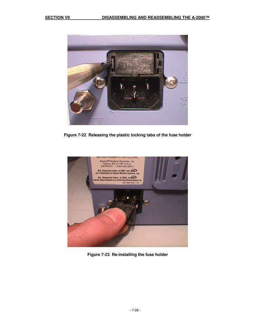
SECTION VII DISASSEMBLING AND REASSEMBLING THE A-2000™
- 7-28 -
Figure 7-22 Releasing the plastic locking tabs of the fuse holder
Figure 7-23 Re-installing the fuse holder
SECTION VIII A-2000™ SPECIFICATIONS
- 8-1 -
SECTION VIII
8. A-2000 SPECIFICATIONS
INTRODUCTION This section lists specifications for the Aspect A-2000 BIS Monitor.
8.1 GENERAL SPECIFICATIONS: • Product Description: BIS (Bispectral Index) monitor for display up to 2
channels of processed data and real-time EEG waveforms
• Monitor Weight: 3.1 lbs (1.4 kg) • Monitor Dimensions: 7.0 in wide x 7.0 in high x 4.0 in deep (17.5 cm x 17.5 cm x 10 cm) • Digital Signal Converter: Weight: 4.7 oz (0.134 kg) including integral cable Dimensions: 2.60 in wide x 1.00 in high x 4.25 in deep (6.6 cm
x 2.5 cm x 10.8 cm) Cable Length: 12 ft (3.7 m) integral DSC cable
3 ft (0.9 m) Patient Interface Cable • Display Size: 3.4 in high x 4.5 in wide (8.5 cm x 11.25 cm) • Digital Output: RS232 serial port, printer port, isolated from
ground • Power Requirements: 100-240 VAC, 50-60 Hz, 1 ampere max. • Electrical Safety: Conforms to: UL 2601, CSA 22.2 No. 601-1 and
IEC 601-1 • Battery Backup: 20 minutes at full operation
Recharge Time: 4 hours • Software Updates: User-via RS-232 serial port • Processors: Texas Instruments TMS 320C32 (50 MHz),
Sharp LH77790 Risc (25 MHz)

SECTION VIII A-2000™ SPECIFICATIONS
- 8-2 -
EEG Specifications: • Epoch Duration: 2 seconds • Artifact Rejection: Automatic
• EEG Scales: 25 µV/div (+/- 1 mV Full Scale) • EEG Sweep Speeds: 25 mm/sec • Computed Parameters: Bispectral Index, 95% Spectral Edge Frequency,
Suppression Ratio, EMG and Signal Quality Index
• User-defined Displays: TREND, DSA and real-time EEG waveforms • Update Rate: 1 second for BIS Index, 10 seconds for
Trend/DSA • Event Markers: User selected • Alarms: Auditory and visual, user adjustable limits • Filters: ON (2 – 70 Hz with notch) or OFF (.25 – 100 Hz) Note: Filter setting does not effect computed
parameters • Mode: Sensor automatically selects mode Digital Signal Converter Specifications: • Analog to Digital Converter: Noise-shaped sigma-delta • Sampling Rate: 16,384 samples/second • Resolution: 16 Bits at 256 samples/second • Input Impedance: 50 Mohms minimum • Noise: < 0.3 mV RMS (2.0 mV peak-to-peak); 0.25 Hz
to 50 Hz • Common Mode Rejection: 110 dB at 60 Hz to earth (Isolation mode) ground • Bandwidth: 0.16 – 800 Hz
SECTION VIII A-2000™ SPECIFICATIONS
- 8-3 -
8.1.1 Type of Protection against Electric Shock of the System: Class 1: Equipment in which protection against electric shock does not rely on basic insulation only, but which includes an additional safety precaution. Means are provided for the connection of the equipment to the protective earth conductor in the fixed wiring of the installation in such a way that accessible metal parts cannot become live in the event of a failure of the basic insulation.
8.1.2 Degree of Protection against Electric Shock of the System: Type BF: Equipment providing a degree of protection against electric shock regarding allowable leakage currents and reliability of the protective earth ground connection with an F-type applied part. An F-type applied part is isolated from all other parts of the equipment to such a degree that the patient leakage current allowable in single fault condition is not exceeded when a voltage equal to 1.1 times the highest rated AC supply voltage is applied between the applied part and earth.
8.1.3 Degree of Protection against the Ingress of Water: Monitor degree of protection rating: IPX2 (ingress of water vertically dripping) at up to 15 degree angle. DSC degree of protection rating: IPX4 (splash proof)
8.1.4 Mode of Operation of the System: Continuous: Operation under normal load for a normal period, without exceeding the specified limits of temperature.
8.1.5 Classification: MEDICAL ELECTRONIC EQUIPMENT
CLASSIFIED BY UNDERWRITERS LABORATORIES INC.®
WITH RESPECT TO ELECTRIC SHOCK, FIRE AND MECHANICAL HAZARDS ONLY IN ACCORDANCE WITH
UL 2601-1, CAN/CSA C22.2 NO. 601.1
8.2 OPTIONS AND ACCESSORIES:
• BIS Sensor
• BIS Sensor Patient Interface Cable
• Sensor Simulator
• Pole Clamp for Monitor
• Monitor Stand
• Printer

SECTION VIII A-2000™ SPECIFICATIONS
- 8-4 -
8.3 Digital Signal Converter (DSC) Connector LEMO – 5 female

SECTION VIII A-2000™ SPECIFICATIONS
- 8-5 -
8.4 WARRANTY
Aspect warrants to the initial Purchaser that the A-2000 BIS monitor and the Digital Signal Converter (“Warranted Product”) will be free from defects in workmanship or materials, when given normal, proper, and intended usage for a period of one year (“Warranty Period”) from the date of its initial shipment to Purchaser. Excluded from this warranty are expendable components and supply items such as, but not limited to, electrodes, cables, and prep solutions. Aspect’s obligations under this warranty are to repair or replace any Warranted Product or part thereof that Aspect reasonably determines to be covered by this warranty and to be defective in workmanship or materials provided that the Purchaser has given notice of such warranty claim within the Warranty Period and the Warranted Product is returned to the factory with freight prepaid. Repair or replacement of Products under this warranty does not extend the Warranty Period. To request repair or replacement under this warranty, Purchaser should contact Aspect at 2 Vision Drive, Natick, Massachusetts 01760, 800-442-2051 or 508-647-2088. Aspect will authorize Purchaser to return the Warranted Product (or part thereof) to Aspect. Aspect shall determine whether to repair or replace Products and parts covered by this warranty and all Products or parts replaced shall become Aspect’s property. In the course of warranty service, Aspect may but shall not be required to make engineering improvements to the Warranted Product or part thereof. If Aspect reasonably determines that a repair or replacement is covered by the warranty, Aspect shall bear the costs of shipping the repaired or replacement Product to Purchaser. All other shipping costs shall be paid by Purchaser. Risk of loss or damage during shipments under this warranty shall be borne by the party shipping the Product. Products shipped by Purchaser under this warranty shall be packaged in the original shipping container or equivalent packaging to protect the Product. If Purchaser ships a Product to Aspect in unsuitable packaging, any physical damage present in the Product on receipt by Aspect (and not previously reported) will be presumed to have occurred in transit and will be the responsibility of Purchaser. This warranty does not extend to any Warranted Products or part thereof: that have been subject to misuse, neglect or accident; that have been damaged by causes external to the Warranted Product, including but not limited to failure of or faulty electrical power; that have been used in violation of Aspect’s instructions; that have been affixed to any nonstandard accessory attachment; on which the serial number has been removed or made illegible; that have been modified by anyone other than Aspect; or that have been disassembled, serviced, or reassembled by anyone other than Aspect, unless authorized by Aspect. Aspect shall have no obligation to make repairs, replacements, or corrections which result, in whole or in part, from normal wear and tear. Aspect makes no warranty (a) with respect to any products that are not Warranted Products, (b) with respect to any products purchased from a person other than Aspect or an Aspect – authorized distributor or (c) with respect to any product sold under a brand name other than Aspect. THIS WARRANTY IS THE SOLE AND EXCLUSIVE WARRANTY FOR ASPECT’S PRODUCTS, EXTENDS ONLY TO THE PURCHASER AND IS EXPRESSLY IN LIEU OF ANY OTHER EXPRESS OR IMPLIED WARRANTIES INCLUDING WITHOUT LIMITATION ANY WARRANTY AS TO MERCHANTABILITY OR FITNESS FOR A PARTICULAR PURPOSE. ASPECT’S MAXIMUM LIABILITY ARISING OUT OF THE SALE OF THE PRODUCTS OR THEIR USE, WHETHER BASED ON WARRANTY, CONTRACT, TORT OR OTHERWISE, SHALL NOT EXCEED THE ACTUAL PAYMENTS RECEIVED BY ASPECT IN CONNECTION THEREWITH. ASPECT SHALL NOT BE LIABLE FOR ANY INCIDENTAL, SPECIAL OR CONSEQUENTIAL LOSS, DAMAGE OR EXPENSE (INCLUDING WITHOUT LIMITATION LOST PROFITS) DIRECTLY OR INDIRECTLY ARISING FORM THE SALE, INABILITY TO SELL, USE OR

SECTION VIII A-2000™ SPECIFICATIONS
- 8-6 -
LOSS OF USE OF ANY PRODUCT. EXCEPT AS SET FORTH HEREIN, ALL PRODUCTS ARE SUPPLIED “AS IS” WITHOUT WARRANTY OF ANY KIND, EITHER EXPRESS OR IMPLIED.

SECTION IX APPENDICES
SECTION IX
9. APPENDICES
9.1 APPENDIX I - A-2000 PARTS LIST This section lists the names of the A-2000 monitor’s assembly parts and part numbers. Use these numbers when ordering an assembly replacement. Part Number
Name Qty Description
070-0015 A-2000 Operating Manual 075-0002 A-2000 Service Manual 1 140-0017 Main PCB Rev 2 1 140-0017 Main PCB Rev 3 1 140-0018 Interconnect PCB Rev 1 1 140-0018 Interconnect PCB Rev 2 1 150-0040 Case 1 150-0041 Bezel 1 150-0045 Switch Set 1 150-0047 Clamp Shoe Assembly 1 150-0048 Gasket for fan 2 151-0003 Front Bezel Assembly 1 185-0071 A-2000 DSC Assembly 1 186-0067 Patient Interface Cable (PIC-S) 1 Patient Interface Cable only; 1 channel
referential, for use with BIS Sensor 186-0105 Sensor Simulator 1 Tool for “Sensor Check” 195-0018 Fan Assembly 1 195-0019 Battery Assembly 1 195-0020 Power Supply PCB Rev 1 1 195-0020 Power Supply PCB Rev 2 1 430-0006 Fuse, 1.25A 250V 5x20 mm 2 465-0012 Electro Luminiscent Display 1 506-0003 Ground Stud 1 Equipotential post 510-0006 Nut for DSC connector 1 605-0036 Nylon screw 1 635-0005 Rubber Foot 4 675-0012 Tie wraps 2 Hold battery in place 675-0017 Rubber bumper, adhesive backed 1 Bumper at rear of case/ reduces PCB vibration 675-0020 Gasket 16.75 inches 1 820-0002 Wrench 1 Tool for removing DSC connector nut

SECTION IX APPENDICES
9.2 APPENDIX II - SENSOR SIMULATOR - INSTRUCTIONS FOR USE Description of device: The sensor simulator is a service tool that allows for the verification of proper impedance values being detected by the BIS monitors during the “Check electrodes”. This test is part of the initial test that each monitor performs. The simulator also allows for safety testing of BIS monitors in the field by allowing connection of the test equipment to the monitor via the patient interface cable. NOTE: The life expectancy of the sensor simulator is 25 connect / disconnect cycles. Figure 1: Schematic of Sensor simulator circuit. S1 – S4 connect to 4 input signal pins on the patient interface cable. The Inputs (+ and -) are where one connects the test signals to test the BIS Monitor. .
Test types allowed: Sensor check: This checks and verifies that the monitor is reporting the proper impedances that it sees from the sensor simulator. This procedure verifies the proper functionality of the BIS monitoring system. Connect the sensor simulator to the BIS Monitor at the patient interface cable. The monitor should proceed to recognize that a sensor was connected and report the proper impedance values:
A-2000: Electrode # Typical Value in K
Ohms Resolution Range in K Ohms
1: 5 4 - 6 2: 10 8 - 12 3: 2 1 - 3
A-1050: Note that values are now displayed in Ohms and not Kilo Ohms. Electrode # Typical Value in Ohms Resolution Range in Ohms
CTR 5400 4400 – 6400 GND 10000 8000 – 121000 L/R 2200 1200 - 3200
The monitor then proceeds to display the BIS screen. After a few seconds the BIS displayed will be 0.

SECTION IX APPENDICES
Safety Testing: Leakage Current. Leakage Current testing should be performed by a qualified Biomedical Engineering Technician or authorized personnel only. � Connect sensor simulator to the patient interface cable of the BIS monitor as if it was
a sensor connection. � Short the two circular terminals at the end of the simulator using conventional
methods such as jumpers or alligator clips. Wire attached with screws will work also. � Connect the test signal to the shorted terminals. Make sure that you are not touching
the simulator beyond this point. Proceed to test instrument for Leakage current as per established facility protocols and procedure for safety testing of medical devices.
For technical assistance contact: Aspect Medical Systems, Inc. Technical Service 2 Vision Drive Natick, MA 01760 (800)442-2051 (USA) (508)653-0603


Contact Information for:
Aspect Medical Systems, Inc. 2 Vision Drive Natick, MA 01760-2059 U.S.A.
Main Business Phone: (508) 653-0603 Main Business Fax: (508) 653-6788 Customer Service: (888) BIS-INDE(X)…press (6)
OR (800) 442-7688 … press (6) Technical Service: (800) 442-2051 Email: [email protected] Web: www.aspectms.com
Aspect Medical Systems International B.V. Haagse Schouwweg 8 2332 KG Leiden The Netherlands
Main Business Phone: +31 071 572 5935 Main Business Fax: +31 071 572 5936


![indeX [frankshospitalworkshop.com]frankshospitalworkshop.com/equipment/documents... · technical speciFications Light Conductor Optics fiber 100% coherent which guarantees the passage](https://static.fdocuments.net/doc/165x107/5e876382b2936843fc63528c/index-fr-fr-technical-specifications-light-conductor-optics-fiber-100-coherent.jpg)


![Index [frankshospitalworkshop.com]frankshospitalworkshop.com/equipment/documents/dental...Chair, Dental and Water Units and Dental Light) supplied by Gnatus authorized Dealers / Technical](https://static.fdocuments.net/doc/165x107/5e8fc8096499cd0569748cee/index-fr-fr-chair-dental-and-water-units-and-dental-light-supplied-by-gnatus.jpg)


![BISPECTRAL AND DUALITIES, arXiv:math/0605172v1 [math.QA] 7 ... · arXiv:math/0605172v1 [math.QA] 7 May 2006 BISPECTRAL AND (glN,glM) DUALITIES, DISCRETE VERSUS DIFFERENTIAL E. MUKHIN](https://static.fdocuments.net/doc/165x107/5f0779787e708231d41d29ac/bispectral-and-dualities-arxivmath0605172v1-mathqa-7-arxivmath0605172v1.jpg)