A 2 Element Quad for 17 and 12 Meters Using a Combined Feed
5
From April 2007 QST © ARRL F or many hams, 17 and 12 meter operation calls for smaller and less complex beams than we use for the other HF bands. A two band, two element quad beam with a common feed point is one good solution to the antenna challenge on these bands — if we can obtain performance equivalent to monoband quads for the same bands. The following project is a joint venture between two old friends, W4RNL and WA1FXT, separated by two state lines and many miles. W4RNL provided the design work and analysis, while WA1FXT constructed and tested the prototype. Despite the distance between collaborators, the project proved to be very successful. Where to Start The best place to begin the design of a dual-band quad is with a good monoband design. Several years ago, W4RNL developed a number of monoband quad programs and models based on regression analysis of a detailed series of models. The results are available in several formats, A 2 Element Quad for 17 and 12 Meters Using a Combined Feed L. B. Cebik, W4RNL, and Robert Cerreto, WA1FXT including a NEC Win Plus model and spread- sheets. 1 The program requires you to enter the design frequency and the wire diameter. The calculations produce two element quads with good gain, good front-to-back ratios and the broadest bandwidth that is obtainable for any given element diameter. Figure 1 shows the general outline and the design-frequency free-space E-plane pattern of one sample from the program. With slight changes in gain that result from the selected element diameter, all quads produced by the program yield essentially the same characteris- tics. The feed point impedance is about 135 Ω resistive. 2 Design Approach We specifically selected this design because it offered broad bandwidth, as quads go. Generally, quad beams struggle for SWR bandwidth on the wider ham bands. They struggle even harder to obtain a good front-to- back ratio, which tends to peter out more quickly than the SWR bandwidth. A wide operating bandwidth ensures against the inevitable home workshop con- struction variables that throw a design off its modeled preci- sion. As well, when we combine designs into a multi-band beam, 1 Notes appear on page 37. Figure 1 — General layout and free-space E-plane (azimuth) pattern of a basic two element monoband quad beam designed for optimal performance.
Transcript of A 2 Element Quad for 17 and 12 Meters Using a Combined Feed

From April 2007 QST © ARRL
F or many hams, 17 and 12 meter operation calls for smaller and less complex beams than we use for the other HF bands. A two band, two element quad beam with a common feed point is one good solution to the antenna challenge on these bands — if we can obtain performance equivalent to monoband quads for the same bands. The following project is a joint venture between two old friends, W4RNL and WA1FXT, separated by two state lines and many miles. W4RNL provided the design work and analysis, while WA1FXT constructed and tested the prototype. Despite the distance between collaborators, the project proved to be very successful.
Where to StartThe best place to begin the
design of a dual-band quad is with a good monoband design. Several years ago, W4RNL developed a number of monoband quad programs and models based on regression analysis of a detailed series of models. The results are available in several formats,
A 2 Element Quad for 17 and 12 Meters Using a Combined FeedL. B. Cebik, W4RNL, and Robert Cerreto, WA1FXT
including a NEC Win Plus model and spread-sheets.1
The program requires you to enter the design frequency and the wire diameter. The calculations produce two element
quads with good gain, good front-to-back ratios and the broadest bandwidth that is obtainable for any given element diameter. Figure 1 shows the general outline and the design-frequency free-space E-plane pattern of one sample from the program. With slight changes in gain that result from the selected
element diameter, all quads produced by the program yield essentially the same characteris-tics. The feed point impedance is about 135 Ω resistive.2
Design ApproachWe specifically selected
this design because it offered broad bandwidth, as quads go. Generally, quad beams struggle for SWR bandwidth on the wider ham bands. They struggle even harder to obtain a good front-to-back ratio, which tends to peter out more quickly than the SWR bandwidth. A wide operating bandwidth ensures against the inevitable home workshop con-struction variables that throw a design off its modeled preci-sion. As well, when we combine designs into a multi-band beam,
1Notes appear on page 37.
Figure 1 — General layout and free-space E-plane (azimuth) pattern of a basic two element monoband quad beam designed for optimal performance.
From April 2007 QST © ARRL
A 2 Element Quad for 17 and 12 Meters Using a Combined Feed
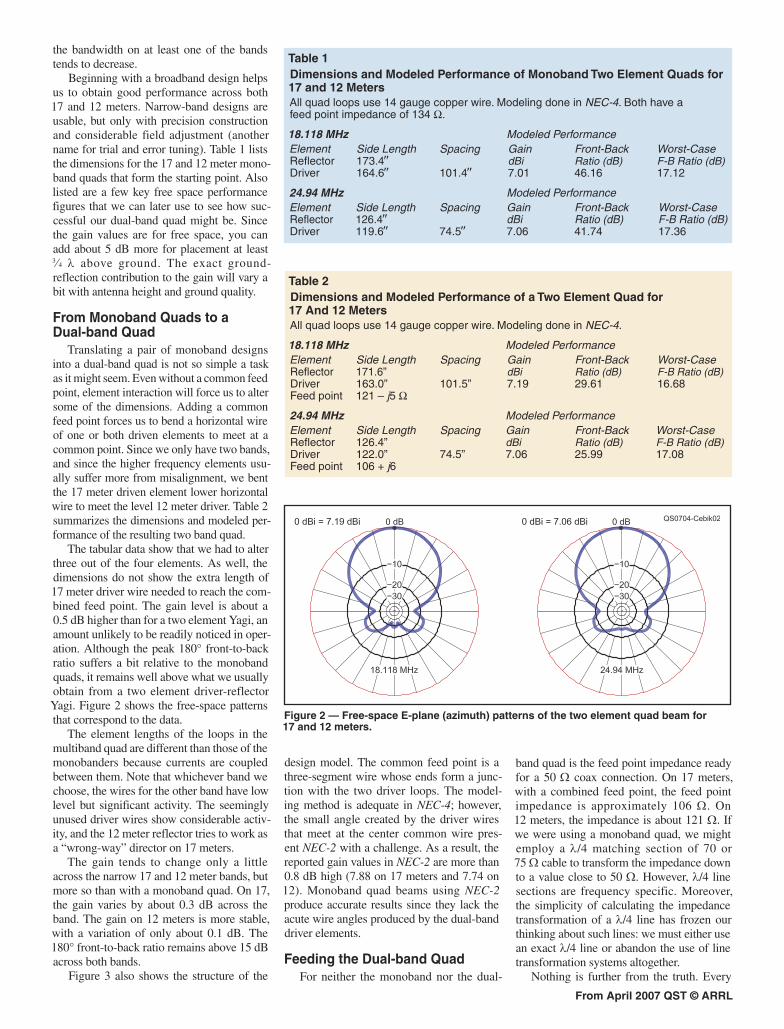
Figure 2 — Free-space E-plane (azimuth) patterns of the two element quad beam for 17 and 12 meters.
the bandwidth on at least one of the bands tends to decrease.
Beginning with a broadband design helps us to obtain good performance across both 17 and 12 meters. Narrow-band designs are usable, but only with precision construction and considerable field adjustment (another name for trial and error tuning). Table 1 lists the dimensions for the 17 and 12 meter mono-band quads that form the starting point. Also listed are a few key free space performance figures that we can later use to see how suc-cessful our dual-band quad might be. Since the gain values are for free space, you can add about 5 dB more for placement at least 3⁄4 λ above ground. The exact ground- reflection contribution to the gain will vary a bit with antenna height and ground quality.
From Monoband Quads to a Dual-band Quad
Translating a pair of monoband designs into a dual-band quad is not so simple a task as it might seem. Even without a common feed point, element interaction will force us to alter some of the dimensions. Adding a common feed point forces us to bend a horizontal wire of one or both driven elements to meet at a common point. Since we only have two bands, and since the higher frequency elements usu-ally suffer more from misalignment, we bent the 17 meter driven element lower horizontal wire to meet the level 12 meter driver. Table 2 summarizes the dimensions and modeled per-formance of the resulting two band quad.
The tabular data show that we had to alter three out of the four elements. As well, the dimensions do not show the extra length of 17 meter driver wire needed to reach the com-bined feed point. The gain level is about a 0.5 dB higher than for a two element Yagi, an amount unlikely to be readily noticed in oper-ation. Although the peak 180° front-to-back ratio suffers a bit relative to the monoband quads, it remains well above what we usually obtain from a two element driver-reflector Yagi. Figure 2 shows the free-space patterns that correspond to the data.
The element lengths of the loops in the multiband quad are different than those of the monobanders because currents are coupled between them. Note that whichever band we choose, the wires for the other band have low level but significant activity. The seemingly unused driver wires show considerable activ-ity, and the 12 meter reflector tries to work as a “wrong-way” director on 17 meters.
The gain tends to change only a little across the narrow 17 and 12 meter bands, but more so than with a monoband quad. On 17, the gain varies by about 0.3 dB across the band. The gain on 12 meters is more stable, with a variation of only about 0.1 dB. The 180° front-to-back ratio remains above 15 dB across both bands.
Figure 3 also shows the structure of the
design model. The common feed point is a three-segment wire whose ends form a junc-tion with the two driver loops. The model-ing method is adequate in NEC-4; however, the small angle created by the driver wires that meet at the center common wire pres-ent NEC-2 with a challenge. As a result, the reported gain values in NEC-2 are more than 0.8 dB high (7.88 on 17 meters and 7.74 on 12). Monoband quad beams using NEC-2 produce accurate results since they lack the acute wire angles produced by the dual-band driver elements.
Feeding the Dual-band QuadFor neither the monoband nor the dual-
band quad is the feed point impedance ready for a 50 Ω coax connection. On 17 meters, with a combined feed point, the feed point impedance is approximately 106 Ω. On 12 meters, the impedance is about 121 Ω. If we were using a monoband quad, we might employ a λ/4 matching section of 70 or 75 Ω cable to transform the impedance down to a value close to 50 Ω. However, λ/4 line sections are frequency specific. Moreover, the simplicity of calculating the impedance transformation of a λ/4 line has frozen our thinking about such lines: we must either use an exact λ/4 line or abandon the use of line transformation systems altogether.
Nothing is further from the truth. Every
Table 2Dimensions and Modeled Performance of a Two Element Quad for 17 And 12 MetersAll quad loops use 14 gauge copper wire. Modeling done in NEC-4.
18.118 MHz Modeled PerformanceElement Side Length Spacing Gain Front-Back Worst-CaseReflector 171.6” dBi Ratio (dB) F-B Ratio (dB)Driver 163.0” 101.5” 7.19 29.61 16.68Feed point 121 – j5 Ω
24.94 MHz Modeled PerformanceElement Side Length Spacing Gain Front-Back Worst-CaseReflector 126.4” dBi Ratio (dB) F-B Ratio (dB)Driver 122.0” 74.5” 7.06 25.99 17.08Feed point 106 + j6
Table 1Dimensions and Modeled Performance of Monoband Two Element Quads for 17 and 12 MetersAll quad loops use 14 gauge copper wire. Modeling done in NEC-4. Both have a feed point impedance of 134 Ω.
18.118 MHz Modeled PerformanceElement Side Length Spacing Gain Front-Back Worst-CaseReflector 173.4″ dBi Ratio (dB) F-B Ratio (dB)Driver 164.6″ 101.4″ 7.01 46.16 17.12
24.94 MHz Modeled PerformanceElement Side Length Spacing Gain Front-Back Worst-CaseReflector 126.4″ dBi Ratio (dB) F-B Ratio (dB)Driver 119.6″ 74.5″ 7.06 41.74 17.36

From April 2007 QST © ARRL
Figure 3 — General structural layout of the 17-12 meter two element quad beam with a common feed point.
length of line transforms the impedance at the antenna end by an amount that is a function of the electrical length of the line. A quarter-wavelength at 18.118 MHz is 163 inches and at 24.94 MHz is 118.3 inches. Perhaps an intermediate line length might yield accept-able terminal impedance values on both bands. A length of 140 inches of 75 Ω cable works best, but most cables today are closer to 70 Ω. A 145 inch length of 70 Ω cable has an electrical length of about 0.22 λ on 17 meters and 0.31 λ on 12 meters. The result is a 17 meter 50 Ω SWR that is below 1.4:1 across the narrow band. On 12 meters, the 50 Ω SWR is under 1.3:1 across the band.
The electrical length of the suggested 70 Ω matching section is 145 inches. The physical length will be 145 inches times the velocity factor of the line actually used. Velocity factors of commonly available 70 Ω line range from about 0.66 to 0.8, depending on the dielectric material used between the braid and the center wire. If you can, measure the velocity factor of the line that you have, since the value may vary from the published or catalog value. However, the precise line length for the matching section is not exceedingly critical. For example, the prototype used a slightly shorter line with completely acceptable results.
The distance between the feed point plate and the hub is about 72 inches. Therefore, the line can go over the hub and partway down the mast. If you use a rotator, there is enough matching section line at the hub to form the
stress relief loop that goes around the rotator. Tape the coax to a support rope, since coaxial cables are not designed to bear weight loads. At the junction of the 70 Ω match line and the main 50 Ω cable, install a common-mode current attenuator. You may use a 1:1 balun, a ferrite bead choke, or a coil of coax. All three systems appear in the current edition of The ARRL Antenna Book.3
Building the 17 and 12 Meter Quad
The dual-band quad uses “spider” quad construction techniques to allow optimum spacing between driver and reflector elements for each band. Optimum spacing helps assure best performance from the antenna. The com-ponent parts for this type of quad are the spi-der hub with spreader support arms, spreader arms to support the wire elements, a mast attachment for the spider hub and spreader arm braces to keep the driver and reflector elements spacing fixed. Table 3 provides a list of materials needed for the project.
Spider HubThe spider hub consists of a short square
boom, eight spreader support arms, a bracket to attach the hub to the mast plate, and a mast plate to attach the hub to a mast. The spider hub can be fabricated with a number of dif-ferent materials. The choice of materials is dependent upon the builder’s preferences, availability, cost, and the tools available to the builder. We chose our materials from what is
commonly available at WA1FXT’s location — 1⁄8 inch steel stock for strength, low cost and availability.
Our quad prototype is built very robustly so it will stand up to the severe winter weather from Lake Erie. If you believe that lighter materials will endure the weather at your location, you may use thinner steel stock or aluminum angle stock, along with smaller diameter spreaders. Steel surfaces will require appropriate corrosion prevention techniques. Aluminum, in addition to being lighter, has the added benefit of not requiring any corrosion protection techniques, but alu-minum stock is more expensive.
Fiberglass tubes are available from a number of sources and are reasonably priced. So, we decided to purchase our spread-ers. We used telescoping fiberglass tubes. Telescoping the fiberglass tubes helps ease some adjustments. The telescoping tubes should be cemented in place after final adjustments. Also, protect all fiberglass sur-faces from damaging sunlight with a coat of flat black paint over a suitable primer.
Other than welding of the spider hub, fab-rication of the quad does not require the use of any exotic tools. The welding required is simple and straightforward. So, paying a pro-fessional welder should not break the budget if you cannot do your own welding.
BoomThe main boom was fabricated by weld-
ing two 12 inch angles together to form a

From April 2007 QST © ARRL
Table 3A List of Materials for the Dual-band Quad
Quantity Material8 Fiberglass tubes for the spreaders, 8′, 11⁄2″8 Fiberglass tubes for the spreaders, 8′, 1″12′ Angle stock for spreader support arms, boom, and boom bracket of 11⁄2 × 11⁄2 × 1⁄8″1 8 × 12 × 1⁄8″ flat plate.16 13⁄4″ stainless steel hose clamps.2 1⁄4 × 2″ stainless steel U-bolts.20′ Fiberglass rod or tube for spreader braces.1 18 × 18 × 1⁄4″ Polycarbonate sheet for element attachments and feed line attachment plate. 75 Ω coax for the impedance matching transmission line.Stranded bare 14 gauge copper wire, as needed for the elements.
Figure 6 — The assembled hub and mast-plate, with a coat of protective primer.
Figure 4 — The spider hub immediately after welding.
Figure 5 — The boom to mast plate attachment: note the 45° angle at the top of the plate and its bolts. This is used to attach the spider hub to the mast plate.
tors. Figure 4 shows the newly welded hub assembly. Fine adjustments to the element spacing can be made later using the flexibility of the spreaders. The element spacing is fixed using braces between the spreader arms.
The boom is attached to the mast plate by bolting it to a 12 inch piece of angle stock welded at a 45° angle to the mast plate. See Figure 5. Before welding the parts, measure the parts twice and cut them once. Be sure that each spreader support arm is at the cor-rect angle, that it is spaced on the boom cor-rectly, and that the assembly is symmetrical. These precautions will assure you that the antenna elements will be placed close to the modeled dimensions. A carefully con-structed spider also results in a pretty quad! We found that a simple wooden jig helps hold the support arms in the correct posi-tion during welding. Figure 6 shows the assembled hub after it received its protective primer coat.
SpreadersWe chose fiberglass tube diameters of
11⁄4 inch and 1 inch for the telescoping spread-ers. 1 inch and 3⁄4 inch tubes can be used in lighter designs. If you substitute different materials or sizes for the spreaders, keep in mind that the longevity of your antenna will be determined in part by the strength of the spreaders. Fasten the spreaders to the spreader support arms using stainless steel hose clamps.
The spreaders should be braced to keep the spacing between drivers and reflectors constant when the winds become strong. These braces are located at approximately 71 inches from the boom end of the spreaders. We used 1⁄2 inch PVC and conduit brackets for our braces because that is what we had available. For lighter structures, 3⁄8 inch solid rod should be sufficient. These braces can be lashed with cable ties and cemented in place. Figure 7 reveals the type of arm-to-brace con-nections used in the prototype.
Element ConstructionThe wire elements are attached to the
spreaders using circular polycarbonate plates. Figure 8 displays a sample. The plates are drilled for the spreader diameter and are held in place with cable ties and epoxy cement. We found that stringing the 17 meter elements before stringing the 12 meter elements works best. The approximate attachment points for the elements (as measured from the spider boom) are 17 meter driver — 126 inches, 12 meter driver — 93 inches, 17 meter reflector — 129 inches, 12 meter reflector — 94 inches.
Precise symmetry is not as important as the overall loop circumferences. Try to main-tain the loop circumferences as specified by the model plus some extra slack for adjust-ments and be as symmetrical as you can. Do not permanently fix the loops in place until after final adjustments. Temporary cable ties and electrical tape will hold the elements in place until you finalize the adjustments. Then cement the attachment plates to the support arms permanently.
Feed Point DetailsThe feed point plate is a polycarbonate or
similar plate, as shown on Figure 9. We used a small piece of UV protected PVC that we had in stock. The transmission line matching section attaches to the plate with standard coax fittings and is supported from the mast plate and hub. Transmission line to the shack can be cable tied or taped to the mast, and a current balun should be placed at the junction of the matching line and line to the shack. We used slip on ferrite beads for our balun. Type 43 material worked just fine.
Measurements and MatchingAfter construction, we lifted the quad
about 11 feet above ground for initial test-ing. We also remodeled the quad at its test height to have some performance numbers with which to compare test measurements. Next, we measured and adjusted each set of elements and measured the feed point imped-ances using separate feed points.
The 17 meter feed point impedance ini-tially showed a negative reactance, so the
perfectly square tube. This square boom sets the 90° angles between the spreader arms. The spreader support arms are 12 inches long with a 21° angle cut into one end. The angled ends of the support arms are welded in place about 9 inches apart on the boom. The spac-ing between the support arms and the angle at which they meet the main boom roughly set the spacing between the drivers and reflec-

From April 2007 QST © ARRL
Figure 7 — The arm-to-brace connectors used in the prototype quad.
Figure 9 — The prototype feed point plate.
Figure 8 — Here is our polycarbonate element attachment plate: do not use a loop of wire at the corners to reinforce the elements. The loops can detune the elements.
Table 4Measured 17 and 12 Meter 50 Ω SWR Values for the Combined-feed Quad using 115 Inches of 75 Ω Coax with a Velocity Factor of 0.8
17 Meters Freq MHz 50 Ω R (Ω) X (Ω) Z (Ω) SWR18.074 1.15 51.1 5.5 51.418.104 1.17 49.6 7.0 50.218.134 1.18 48.4 8.2 49.218.144 1.20 47.9 8.8 48.818.174 1.22 46.9 8.7 47.7
12 Meters Freq MHz 50 Ω R (Ω) X (Ω) Z (Ω) SWR24.89 1.55 62.8 20.9 66.324.92 1.55 62.2 21.1 65.824.95 1.55 61.9 21.4 65.524.98 1.55 61.6 21.6 65.4
element loop lengths were changed until we were close to what the modeling predicted over real ground. The 12 meter feed point impedance was then measured and adjusted in the same manner. We then joined both drivers for a common feed point. Next, we measured the combined feed point imped-ance and we found that the 17 meter imped-ance was approximately 130 Ω, while the 12 meter impedance was approximately 132 Ω. These values will decrease at higher positions above ground.
The actual prototype loop lengths for the elements were within 1.5% of the mod-eled dimensions, even at the low test height. These loop lengths were 17 meter driver — 663 inches, 12 meter driver — 482 inches, 17 meter reflector — 691 inches, and 12 meter reflector — 511 inches. The spacing between the drivers and reflectors was 102 inches for 17 meters and 75 inches for 12 meters. Relative to a tight correlation between final construction dimensions and initial models, the use of closed loops in quads tends to cre-ate a larger set of construction variables than we usually find for beams with linear ele-ments. We attributed differences between the modeled data and measured data to such fac-tors as slack in the wires, mechanical errors, proximity to ground, and ground composi-tion assumptions.
The combined feed point impedance is not the 50 Ω our rig likes to see. So, it had to be transformed from about 130 Ω to 50 Ω on each band. The coax that we used has a nominal impedance of 75 Ω and the velocity factor is 0.8. Using these values, the approxi-mate feed point impedance of the quad, and the frequency of the model, a utility program calculated physical line lengths of 11.46 feet (or about 95° electrical length) for 17 meters and 8.33 feet (or about 95° electrical length) for 12 meters. The average physical length for both these lines is about 115 inches (equiva-lent to about 144 inches electrically). Using the average value of the physical lengths, the predicted SWR for both bands is reasonable. So, we cut our matching line to 115 inches and added it to the quad feed point.
Table 4 summarizes the measured SWR results that we obtained at the transmitter. These measurements were acceptable to us, so we made no further adjustments. You may choose to optimize them further for your needs. Keep in mind that the test readings are at the test height of 11 feet. They will change as the antenna is raised above the test height. Hence, you may have to adjust the match-ing line section length when you raise the antenna to its final operating position.
We also measured the front-to-back ratio at the test height, even though the height is low compared to a normal operating position. Our measurements were done at a distance of about 200 feet from the quad using a
calibrated S-meter and known power source driving the antenna. We measured 14 dB for 17 meters and 20 dB for 12 meters. These values compare favorably with the modeling numbers for this height. They will improve as the antenna is raised to its final height.
ConclusionThe design exercise and the resulting pro-
totype confirm that it is possible to create a very good dual-band two element quad beam for 17 and 12 meters using a common feed point if we adhere to a few key principles. First, we must begin with the best possible monoband designs and combine them with attention to the interactions between active and supposedly inactive elements. An initial broadband design minimizes both design and adjustment time on the version with com-bined feed points. Second, we must construct the antenna carefully with special attention to the support structure. Third, we should go to the trouble of carefully adjusting the assembled quad to produce the desired per-formance. A home-brew dual-band quad with a common feed point is not a “kit” project that automatically assures success. Instead, it is a project in which we can achieve success according to the care and patience we put into each stage of the work.
Notes1For a spreadsheet version of the design
program, see www.cebik.com//trans/ant-design.html.
2Models used in the design phases of this proj-ect appear at the ARRL Web site at www.arrl.org/files/qst-binaries/cebik0407.zip.
3R. D. Straw, Editor, The ARRL Antenna Book, 20th Edition. Available from your ARRL dealer or the ARRL Bookstore, ARRL order no. 9043. Telephone 860-594-0355, or toll-free in the US 888-277-5289; www.arrl.org/shop/; [email protected].
Bob Cerreto, WA1FXT, is a Senior Engineer with a major dc power systems supplier. Back in Connecticut, Bob was first licensed in 1965 as WN1FXT. Since then, the ham radio world for Bob has been filled with many homebrew projects. He feels most comfortable in his radio lab and woodworking shop with fellow hams and grandchildren. Since moving to Ohio in 1984, his backyard has become a three-acre antenna breadboard. Bob’s wife Judith, KC8BOM, serves as a catalyst for his ham radio ventures and is an accomplished builder, too.Bob can be reached at 49015 Middle Ridge Rd, Amherst, OH 44001 or [email protected].
Since his retirement as a professor at the University of Tennessee, L. B. Cebik, W4RNL, has written extensively for radio amateurs about antennas and related topics in many venues, including his own Web site, www.cebik.com. Licensed since 1954, LB has served ARRL in many capacities, including Educational Advisor and Technical Advisor. He is a con-tributing editor to QEX and is technical edi-tor for antenneX. LB can be reached at 1434 High Mesa Dr, Knoxville, TN 37938-4443 or [email protected].