
9710 and 9720 Wedge Readers - S&PSepsfiles.intermec.com/eps_files/eps_man/055875.pdf · 3-24 39...
138
P/N 055875-004 9710 and 9720 Wedge Readers User’s Manual
Transcript of 9710 and 9720 Wedge Readers - S&PSepsfiles.intermec.com/eps_files/eps_man/055875.pdf · 3-24 39...

P/N 055875-004
9710 and 9720 Wedge Readers
User’sManual

Intermec Technologies Corporation6001 36th Avenue WestP.O. Box 4280Everett, WA 98203-9280
U.S. service and technical support: 1-800-755-5505U.S. media supplies ordering information: 1-800-227-9947
Canadian service and technical support: 1-800-688-7043Canadian media supplies ordering information: 1-800-268-6936
Outside U.S. and Canada: Contact your local Intermec servicesupplier.
The information contained herein is proprietary and is providedsolely for the purpose of allowing customers to operate and/orservice Intermec manufactured equipment and is not to be released,reproduced, or used for any other purpose without writtenpermission of Intermec.
Information and specifications in this manual are subject to changewithout notice.
1997 by Intermec Technologies CorporationAll Rights Reserved
The word Intermec, the Intermec logo, JANUS, IRL, TRAKKER,Antares, Duratherm, Precision Print, PrintSet, Virtual Wedge, andCrossBar are either trademarks or registered trademarks of IntermecCorporation.
Throughout this manual, trademarked names may be used. Ratherthan put a trademark ( or ) symbol in every occurrence of atrademarked name, we state that we are using the names only in aneditorial fashion, and to the benefit of the trademark owner, with nointention of infringement.

Manual Change Record
This page records the changes to this manual. The manual wasreleased at Revision A. Please note that since the release of thismanual, we have switched to a numbered revision system.
Revision Date Description of Change
B 8/91 Glossary, Index and information on multiple keyremapping were added.
-001 12/93 A new parameter was added to UPC/EANcode. You can decode UCC/EAN 128 fromCode 128 symbology. Some other minorchanges were made to Chapter 3.
-002 7/95 Added one bar code (supplemental required) tothe fourth parameter of the UPC/EANsymbology on page 3-34 and one correction topage 3-24.
-003 7/97 Added information about ISBT 128 bar codesymbology. Also combined the 9710 and 9720manuals into one manual.
-004 11/97 Corrected keyboard mapping tables inAppendix.


Co d e 39Contents
v
Contents
Manual Change Record iii
Before You Begin ix
Warranty Information ix
Safety Summary ix
About This Manual x
Other Intermec Manuals xii
Getting Started
Preparing for Installation 1-3
Connecting the Reader to the Workstation 1-4
Installing the Reader 1-5
Connecting an Input Device 1-6
Using a Power Supply 1-7
Is Additional Power Required? 1-7
Checking Connections 1-8
Applying Power 1-9
Identifying the Workstation Type 1-9
Checking Communications 1-10
Troubleshooting 1-11
Mounting the Reader 1-11
Operating the Reader
How to Use the Reader 2-3
Reading Bar Codes 2-4
Using Reader Commands 2-5
1
2

9710 and 9720 Wedge Readers User�s ManualCODE39
vi
Backspace (Destructive) 2-5
Change Configuration 2-5
Clear 2-5
Default Configuration 2-6
Enter 2-6
Enter Accumulate 2-6
Exit Accumulate 2-7
Reset 2-7
Transmit Message 2-7
External Headphone/Speaker Jack 2-8
9720 Serial Port 2-8
Status Beeps 2-8
Configuring the Reader
Default Reader Configuration 3-3
Configuration Parameters 3-6
Beeper Volume 3-6
Caps Lock 3-6
Command Processing 3-7
Data Redirection 3-10
Wait Character 3-11
Wait Time 3-12
Intercharacter Delay 3-15
Preamble 3-15
Postamble 3-19
Scanner Trigger 3-21
Scanner Mode 3-21
Scanner Timeout 3-22
Voting 3-23
Bar Code Symbologies 3-24
Code 11 3-24
3

Co d e 39Contents
vii
Code 39 3-24
Code 49 3-29
Code 93 3-30
Code 128 and ISBT 128 3-31
Code 16K 3-33
Codabar 3-34
Interleaved 2 of 5 Code 3-36
2 of 5 Code 3-37
Plessey Code 3-39
MSI Code 3-39
Universal Product (UPC)/European ArticleNumbering (EAN) Codes 3-41
Customizing ASCII to Keyboard Equivalents 3-45
Configuring the 9720 Serial Port
Connecting to the Serial Port 4-3Connecting a Portable Reader 4-4
Connecting a Scale 4-5
Uploading Data 4-6Uploading Data From a Portable Reader 4-6
Uploading Data From a Scale 4-7
Serial Port Configuration Parameters 4-8
Baud Rate 4-8
Parity 4-8
Data Bits 4-9
Stop Bits 4-9
Timeout Delay 4-10
Echo 4-11
Flow Control 4-11
RXEOM 4-12
TXEOM 4-13
Solicitation Message 4-14
4

9710 and 9720 Wedge Readers User�s ManualCODE39
viii
Data Edit Application
Running Data Edit 5-3
Using Data Edit Configuration Parameters 5-3
Application Program 5-3
Window 5-4
Data Begin and Data End 5-5
Data Source 5-7
Data Identifier 5-7
User-Defined Pattern 5-9
Specifications
Mechanical Specifications A-3
Environmental Specifications A-3
Keyboard Equivalent Tables A-3
PC/Workstation Keyboard Mapping A-4
Twinax/Coax Terminal Keyboard Mapping A-5
ASCII Terminal Keyboard Mapping A-6
ASCII Characters Table A-7
Glossary
Index
5
A
G
I

CODE39 Before You Begin
ix
Before You Begin
This section introduces you to standard warranty provisions, safetyprecautions, document formatting conventions, and sources ofadditional product information. A documentation roadmap is alsoprovided to guide you in finding the appropriate information.
Warranty InformationTo receive a copy of the standard warranty provision for thisproduct, contact your local Intermec support services organization.In the U.S. call 1-800-755-5505, and in Canada call 1-800-688-7043.Otherwise, refer to the Worldwide Sales & Service list that ships withthis manual for the address and telephone number of your Intermecsales organization.
Safety SummaryYour safety is extremely important. Read and follow all warningsand cautions in this book before handling and operating Intermecequipment. You can be seriously injured, and equipment and datacan be damaged if you do not follow the safety warnings andcautions.
Do not repair or adjust alone Do not repair or adjust energizedequipment alone under any circumstances. Someone capable ofproviding first aid must always be present for your safety.
First aid Always obtain first aid or medical attention immediatelyafter an injury. Never neglect an injury, no matter how slight itseems.
Resuscitation Begin resuscitation immediately if someone is injuredand stops breathing. Any delay could result in death. To work on ornear high voltage, you should be familiar with approved industrialfirst aid methods.

9710 and 9720 Wedge Readers User�s ManualCODE39
x
Energized equipment Never work on energized equipment unlessauthorized by a responsible authority. Energized electrical equipmentis dangerous. Electrical shock from energized equipment can causedeath. If you must perform authorized emergency work on energizedequipment, be sure that you comply strictly with approved safetyregulations.
About This ManualThis manual contains information necessary to install, operate,configure, troubleshoot, and maintain the 9710 and 9720 WedgeReaders.
What You Will Find in This Manual
This table summarizes the information in each chapter of thismanual:
For Information On Refer To
Installing the reader Chapter 1, “Getting Started.” This chapter tells youhow to install the reader in your data collectionsystem, configure the reader for your specificworkstation, and check for communications.
Operating thereader
Chapter 2, “Operating the Reader.” This chapterexplains the commands you need to use to operatethe reader.
Configuring thereader
Chapter 3, “Configuring the Reader.” This chaptercontains all of the configuration parameters thatyou can use to customize reader operation to meetyour specific system needs.
Using the 9720 serialport
Chapter 4, “Configuring the 9720 Serial Port.” Thischapter describes how to use the serial port on the9720 reader to communicate with a portable readeror a scale.
Using the Data Editapplication
Chapter 5, “Data Edit Application.” This chaptertells you how to use Data Edit to strip specificcharacters from a data record before transmittingthat record to a workstation, portable reader, orscale.
Terms and Conventions
The following special terms and conventions occur throughout thismanual.

CODE39 Before You Begin
xi
• “Wedge reader,” and “reader” refer to the 9710 and 9720 wedgereaders. Unless specifically stated, all information in this manualapplies to both reader models.
• “9710” refers to the 9710 Wedge Reader.
• “9720” refers to the 9720 Wedge Reader.
• “Workstation” refers to a personal computer or other computerthat communicates with the reader.
• Commands and configuration parameters appear in the order youenter them into the reader with the following conventions:
Convention Description
< > Angle brackets enclose mnemonic representations ofASCII control characters. For example, <ETX>represents the ASCII “End of Text” control character.
data Italic text represents variable data, which you mustreplace with a real value. For example, n signifies avariable for which you must designate a constantvalue.
Ctrl Bold text represents a key on your keypad. Forexample, Ctrl represents the Ctrl key and Mrepresents the letter M key.
Ctrl-C When two keys are joined with a dash, press themsimultaneously. For example, if you see the commandCtrl-C, press the two keys at the same time.
Format Conventions for Bar Codes
You can scan the bar codes listed in this manual to enter data orperform a command. The bar code labels in this manual are printedin the Code 39 symbology. Each bar code includes the name andhuman-readable interpretation. For example:
*$+*
Change Configuration
*$+*
Name
Bar code (Code 39)
Human-readableinterpretation
2010U.073

9710 and 9720 Wedge Readers User�s ManualCODE39
xii
The asterisks (*) at the beginning and end of the human-readableinterpretation are the start and stop codes for a Code 39 bar codelabel. If you are creating bar code labels with a bar code utility, it mayautomatically supply the asterisks as the start and stop code, so thatyou only need to type the actual text of the command. You can alsocreate and print configuration labels and reader command labels inCode 93, which has its own start and stop codes.
Other Intermec Manuals
The following manuals provide additional information about usingthe reader and working with bar codes.
Manual Intermec P/N
Data Communications Reference Manual 044737
The Bar Code Book by Roger C. Palmer 051241
9440/44/45 Trakker Operator’s Guide 053397
9440/44/45 Trakker User’s Manual 049273
9460 Trakker Operator’s Guide 053014
9460 Trakker User’s Manual 053012
9462 Trakker Operator’s Guide 053141
9462 Trakker User’s Manual 053143
Introduction to IRL Programming Manual 045025
IRL Programmer’s Reference Manual 048609

Getting Started
1


Getting Started
1-3
1The 9710 and 9720 Wedge Readers connect between the computer
workstation and the workstation keyboard. The wedge reader transmits
information from the bar codes you scan to the computer workstation. The
bar code data displays on the monitor in the same format as if it was
entered from the workstation keyboard. The wedge reader translates all of
the 128 ASCII characters into valid keystrokes.
Preparing for Installation
Your wedge reader package includes the following parts:
• 9710 or 9720 Wedge Reader
• Velcro fasteners
Unpack the shipping carton and verify the contents with the packingslip. Keep the packing box; it is the approved shipping container forthe reader. Use this box if you need to return the reader to Intermec.
These items are packaged separately from the reader:
• Wand or scanner
• Adapter cable
• Power supply (if required)
The following figure shows a 9720 Wedge Reader installed in atypical data collection system. Only the 9720 Wedge Reader has aserial port that can connect to a portable reader or a scale.

9710 and 9720 Wedge Readers User�s Manual
1-4
1 2 3
keyboard
terminal
inputaudio
power
AVOID
EXPOSURE
Laser light is
Emitted fro
m
this Aperture
EVITER
TOUTE
EXPOSITION
Lumiere Laser
Emis par cette
ouverture
1545
®
PowerSupply
Headset
Scanner
SlotScanner
Wand
9720 Wedge Reader
PortableReader
Scale
Workstation
Connecting the Reader to the Workstation
There are two cables for connecting the reader to your workstation: areader/keyboard cable that connects the keyboard to the reader anda reader/workstation cable that connects the reader to theworkstation. Each cable has a ten-position modular connector toconnect to the reader.
The cable package contains a Wedge Interface (WIF) guide thatprovides information on configuring the reader for your workstation.Retain the WIF guide for future reference.

Getting Started
1-5
1Installing the Reader
1. Turn off the workstation and disconnect the keyboard cable fromthe workstation.
2. Connect the reader/workstation cable “PC/Terminal” connectorto the keyboard connector on the workstation and connect themodular connector to the “terminal” connector on the reader.
3. Connect the reader/keyboard cable “Keyboard” connector to theworkstation keyboard cable and connect the modular connector tothe “keyboard” connector on the reader.
The cable connectors only fit one way. If the connector does not fit,do not force it or you may damage the connector. The followingfigure shows how the reader connects to your workstation.
Note: Do not use a cable extender with the reader cables. A cable extenderwill add noise to the line.
1 2 3
keyboard
terminal
inputaudio
power
Reader/Keyboard Cable
Reader/Workstation Cable
1 2 3
keyboard
terminal
input
ReaderConnection
Detail

9710 and 9720 Wedge Readers User�s Manual
1-6
Connecting an Input Device
The reader can receive input from:
• 1260-series wands
• 1500-series scanners
• 1461 CCD scanners
• 1354 and 1355 bar code slot scanners
The wands and scanners require a special cable or an adapter cable toconnect to the ten-position modular connector on the rear panel ofthe reader. If you do not have the correct cable, call your Intermecrepresentative.
To connect a wand or scanner to the reader
• Connect the wand or scanner cable to the “input” modularconnector on the reader rear panel. Make sure that the connectorsnaps into place securely.
1 2 3
keyboard
terminal
inputaudio
power
k
terminal
inputaudio
ower
ConnectionDetail
AVOID
EXPOSURE
Laser light is
Emitted fro
m
this Aperture
EVITER
TOUTE
EXPOSITION
Lumiere Laser
Emis par cette
ouverture
1545
®

Getting Started
1-7
1Using a Power Supply
For most wand and scanner operations, the reader uses power fromthe workstation. If the workstation cannot supply the required powerat +5V for the wand or scanner, the reader requires an additionalpower supply. Your WIF guide lists the workstations that require anexternal power supply.
If your workstation requires a power supply with the reader,continue reading this section. Otherwise, skip to “CheckingConnections” on page 1-8.
Is Additional Power Required?Refer to the list below for part numbers of power supplies thatsupport various voltage requirements.
Voltage Part Number
P100V 50 to 60 Hz, -15% to +10% 054183
P120V 50 to 60 Hz, -15% to +10% 054182
P230V 50 Hz, -15% to +10% 054184
To connect a power supply
1. Attach the power supply connector to the power supplyreceptacle on the reader rear panel.
1 2 3
keyboard
terminal
inputaudio
power
inaudio
power
ReaderConnection
Detail

9710 and 9720 Wedge Readers User�s Manual
1-8
2. Place the PCB jumper on pins 2 and 3.
1 2 3
keyboard
terminal
inputaudio
power
1 2 3
keyboard
1 2 3
keyboard
Without an externalpower supply.
With an externalpower supply.
Note: Do not plug the power supply into the wall outlet until the reader isconnected to the workstation and the keyboard, and you are ready to turn onthe workstation.
Checking Connections
You need to have the following items connected:
• The reader to the workstation and keyboard using the propercables.
• The wand or scanner to the reader.
• The power supply, if required, to the reader. (Make sure the PCBjumper is set correctly.)

Getting Started
1-9
1Applying Power
You are now ready to apply power to the system.
1. If you are using a power supply, plug it into an AC wall outlet.
2. Turn on the workstation.
Note: Do not enter data. The reader must be configured for yourworkstation type before you begin operating the reader.
Identifying the Workstation Type
The default workstation configuration is a null configuration. It isvery important that you configure the reader for your particularworkstation type before operating the reader with the workstation.
Locate your workstation type configuration bar code in the WIFguide and scan the bar code to configure the reader for yourworkstation. The reader emits four low beeps to indicate that theconfiguration was successful. The reader is now ready to read barcodes.
If the reader emits a low/high/low/high beep sequence, the readerfailed the self-test. Scan the Null Configuration bar code. Verify thatyou are using the correct workstation configuration bar code andscan the bar code. If the reader emits the low/high/low/high beepsequence again, contact your Intermec representative.
Null Configuration
*$+TA3**$+TA3*
If you are moving the reader to a different workstation, scan the NullConfiguration bar code before moving the reader. After you installthe reader, reconfigure the reader for that workstation.
Note: Attempting to read bar codes before the workstation type has beenidentified causes the reader to operate improperly. If this occurs, cycle thepower to the workstation and scan the appropriate workstation configurationbar code.

9710 and 9720 Wedge Readers User�s Manual
1-10
Checking Communications
Now you are ready to scan the test bar codes to checkcommunications. The reader emits one high beep each time itsuccessfully translates a bar code. The workstation monitor displaysthe data with the cursor immediately following the data.
To check communications
1. Scan this bar code:
Test Label
*TEST LABEL**TEST LABEL*
The workstation monitor displays TEST LABEL.
2. Scan this bar code:
Test Label
*123456789**123456789*
The workstation monitor displays 123456789.
3. Advance the cursor using the cursor control key or tab key onyour keyboard to make it easier to see the data.
4. Scan this bar code:
Test Label
*97XX READER**97XX READER*
The workstation monitor displays 97XX READER.
To further demonstrate the operation of the reader, scan any of thebar codes on the ASCII charts located at the back of this manual.These bar codes are in Code 39. The reader interprets the data andtransmits it to the workstation monitor.

Getting Started
1-11
1Troubleshooting
If you are unable to successfully transmit the test data, review thefollowing checklist.
✓ Check workstation configuration. Cycle power and scan the barcode for the correct workstation type.
✓ Check the cable connections between the workstation and thereader and the reader and the input device.
✓ If you are using a power supply, check the power connection tothe reader and the wall outlet.
✓ Verify that the PCB jumper on the reader is set correctly.
✓ Verify that the bar codes are good by scanning the bar codes witha reader that you know is good.
Mounting the Reader
You can mount the reader vertically or horizontally using Velcrostrips or screws.
To mount the reader using Velcro strips
1. Take one set of Velcro strips (leave the set connected), remove theadhesive backing from one side, and apply the set to the reader.Repeat this process with the second set of Velcro strips.
2. Remove the backing from the exposed side of the strips and firmlypress the reader to the mounting surface. A good mountingsurface is the side of your workstation monitor.
3. Carefully remove the reader from the mounting surface byseparating the Velcro strips. Ensure that all four strips are firmlyattached to their respective surfaces before remounting the reader.

9710 and 9720 Wedge Readers User�s Manual
1-12
®97
10
To mount the reader using wood screws
• For a more permanent mounting, use two #10 wood screws toattach the reader to a mounting surface. Ensure that the surfaceyou select can handle the alteration. Do not attach the reader tothe workstation monitor using wood screws.
®
9710
The wedge reader is now ready for operation.

Operating the Reader
2


Operating the Reader
2-3
2The reader is easy to operate. To transmit bar code data to your
workstation, you scan bar code labels that contain data, commands, or a
combination of both. The data appears on your workstation monitor as if
you entered it from the keyboard.
How to Use the Reader
The reader uses two operating states:
• Test and Service
• Standard Operation
Note: Some terminal emulation or network hardware or software can affectthe way the workstation operates. This may affect wedge operation.
Test and Service Intermec customer service representatives (CSRs)use this mode to diagnose reader problems. The reader enters Testand Service mode automatically after a self-test failure. A self-testruns at power-on and after a reset. The reader emits a very low beepevery 10 seconds to indicate it is in Test and Service mode.
If the reader enters Test and Service, scan the bar code below. Thereader resets and executes a self-test. If the self-test fails, the readerreturns to Test and Service and you need to contact your Intermecrepresentative.
Reset Command
*-.**-.*
Note: You can configure the reader and run commands when the reader isin Test and Service mode.

9710 and 9720 Wedge Readers User�s Manual
2-4
Standard Operation The reader automatically enters StandardOperation after a successful self-test. Four low beeps indicates thereader is in Standard Operation mode. Standard Operation allowsyou to
• scan bar codes to enter data.
• read and decode various bar code symbologies.
• accumulate scanned data into one record.
• transmit accumulated data.
• add a preamble or a postamble to data.
• build a record or a command.
• configure serial port parameters (9720 only).
Reading Bar Codes
The reader can distinguish between two types of bar codes: regularand multiple-read.
Regular bar codes A regular bar code always takes the form *data*.Typically, the bar code data is transmitted as soon as you scan thebar code. The asterisks (*) are the start and stop characters and arenot transmitted or shown on the workstation monitor. Only thereader uses the asterisks to indicate the beginning and the endingpoints of a bar code. For example, scanning a bar code with the data*TB123* transmits TB123 to the screen.
Multiple-read bar codes Multiple-read bar codes take the form*spacedata*, where “space” is an encoded space and data is theinformation you want to enter. Multiple-read bar codes are nottransmitted to the workstation monitor immediately, but are held inthe reader buffer until the reader receives a transmit command.Multiple-read bar codes allow a record or a command to be builtfrom individual bar codes.
For example, scanning a bar code with the data * TB123* placesTB123 in the reader buffer. The reader must receive a transmitcommand before the data is sent to the workstation. When you scan atransmit command (Enter), TB123 is transmitted to the workstationmonitor. If you scan a regular bar code (like *456*), TB123456 istransmitted to the workstation.

Operating the Reader
2-5
2Using Reader Commands
You use the reader to complete specific tasks by scanning bar codesthat contain one or more commands. Commands are run in the orderthey are located in the command string. Command processing stopswith the first invalid command or at the end of the string. You canuse the following commands with your wedge reader:
Backspace (Destructive)This command deletes the last character of an accumulated datarecord. If there is no accumulated data, the command is invalid.
Backspace
*-+**-+*
Change ConfigurationThis command changes the reader configuration parameters. TheChange Configuration command precedes one or more configurationcommands in a command string or record. When this command runs,reader parameters are modified, the changes are saved in memory,and the reader is reset to allow the changes to take effect.
Change Configuration
*$+**$+*
ClearThis command deletes an entire accumulated data record. If there isno accumulated data, the command is invalid.
Clear
*--**--*

9710 and 9720 Wedge Readers User�s Manual
2-6
Default ConfigurationThis command returns the reader to the factory settings andperforms a self-test. See Chapter 3 for a list of reader default settings.
Default Configuration
*.+**.+*
Note: This command does not reset the workstation type.
EnterThis command transmits accumulated data as a data record to theworkstation. The Enter command is implied when you scan regularbar codes (bar codes without a leading space). If data records are notaccumulated or present in a regular bar code, then a null or emptydata record is transmitted to the workstation.
Enter
****
Enter AccumulateThis command adds all subsequent scanned data to the current databuffer until the count exceeds 256 characters, an Enter bar code isscanned, or an Exit Accumulate bar code is scanned. Data exceeding256 characters causes the reader to emit three low beeps and rejectsthe last bar code read.
Enter Accumulate
*+/**+/*

Operating the Reader
2-7
2Exit AccumulateThis command exits the accumulate feature, transmits theaccumulated data, and clears the data buffer. The readerautomatically exits Accumulate mode whenever the reader is reset.
Exit Accumulate
*-/**-/*
ResetThis command runs the self-test process. Any commands in acommand string that follow the Reset command are lost.
Reset
*-.**-.*
Transmit MessageThis command applies only to the 9720 and transmits the exactsolicitation message (no characters are added) from the 9720 serialport. Refer to Chapter 4 for more information about the SolicitationMessage parameter and the 9720 serial port.
Transmit Message
*..$.**..$.*

9710 and 9720 Wedge Readers User�s Manual
2-8
External Headphone/Speaker Jack
If you use the reader in a noisy environment, you can use aminiature-plug headphone or an amplified, self-powered speaker tohear the reader status beeps. The headphone/speaker jack is labeled“audio” on the reader rear panel.
9720 Serial Port
The 9720 Wedge Reader has an RS-232 serial port on the rear panel.You can connect a portable reader or scale to the serial port andtransfer data from the portable reader or scale through the reader tothe workstation. Refer to Section 4 for information on transferringdata and configuring the serial port.
Status Beeps
The reader speaker emits one or more beeps to indicate statusconditions.
Beep Status
L Valid command or valid data accumulated
H Valid data entered
HL Keystroke not stored in EEPROM
LLL Invalid command or data
HLH I/O error
LLLL Self-test passes
LHLH Self-test fails
E Test and service mode entered
H = high beep L = low beep E = extra low beep

Configuring the Reader
3

Configuring the Reader
3-3
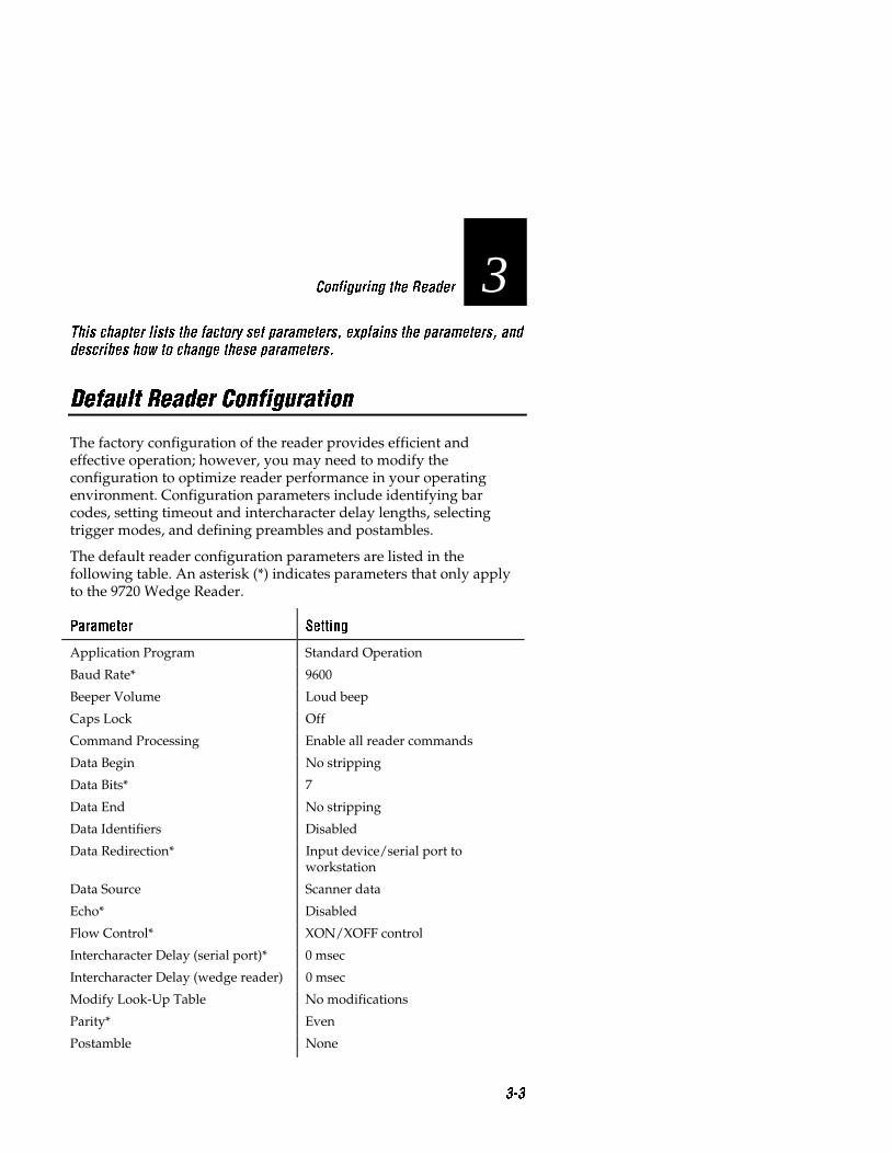
3This chapter lists the factory set parameters, explains the parameters, and
describes how to change these parameters.
Default Reader Configuration
The factory configuration of the reader provides efficient andeffective operation; however, you may need to modify theconfiguration to optimize reader performance in your operatingenvironment. Configuration parameters include identifying barcodes, setting timeout and intercharacter delay lengths, selectingtrigger modes, and defining preambles and postambles.
The default reader configuration parameters are listed in thefollowing table. An asterisk (*) indicates parameters that only applyto the 9720 Wedge Reader.
Parameter Setting
Application Program Standard Operation
Baud Rate* 9600
Beeper Volume Loud beep
Caps Lock Off
Command Processing Enable all reader commands
Data Begin No stripping
Data Bits* 7
Data End No stripping
Data Identifiers Disabled
Data Redirection* Input device/serial port toworkstation
Data Source Scanner data
Echo* Disabled
Flow Control* XON/XOFF control
Intercharacter Delay (serial port)* 0 msec
Intercharacter Delay (wedge reader) 0 msec
Modify Look-Up Table No modifications
Parity* Even
Postamble None

9710 and 9720 Wedge Readers User�s Manual
3-4
Parameter Setting
Preamble A None
Preamble B None
RXEOM* Carriage return line feed
Scanner Mode One-shot
Scanner Timeout No timeout
Scanner Trigger Mode Level
Solicitation Message* No message
Stop Bits* 1
Terminal Type Null
Timeout Delay* 2 sec
TXEOM* Carriage return line feed
Voting Disabled
Wait Character Carriage return
Wait Time No delay
Window Serial port data
Bar Code SymbologiesCode 11 Disabled
Code 39 Full ASCII, no check digit
Code 49 Disabled
Code 49 Function 1 Disabled
Code 49 Function 2 CR LF
Code 93 Disabled
Code 128 Disabled
ISBT 128 Disabled
Code 16K Disabled
Codabar Disabled
Interleaved 2 of 5 Variable length with check digit
2 of 5 Code Disabled
Plessey Disabled
MSI Disabled
UPC A and E; EAN 8 and 13;supplementals
Enabled

Configuring the Reader
3-5
3To set the reader to the factory default configuration
• Scan this bar code.
Default Configuration
*.+**.+*
Before you begin configuring the reader, be sure you are using thecorrect terminal type configuration.
If you are unable to scan the bar code for your workstation type, youcan build the workstation configuration command. Consult your WIFguide for the workstation configuration number or call your Intermecrepresentative for the number.
To build the workstation configuration command
1. Scan this bar code.
Accumulate/Change Config/Workstation Type
*+/$+TA**+/$+TA*
2. Scan the number for your workstation type from the full ASCIIchart at the back of this manual. For example, the IBM PCworkstation configuration number is 1.
3. Scan this bar code.
Exit Accumulate
*-/**-/*

9710 and 9720 Wedge Readers User�s Manual
3-6
Configuration Parameters
Some of the procedures in this chapter require that you scan a barcode from the Code 39 full ASCII chart located at the back of thismanual. When entering data following a command, the data shouldbe enclosed in quotes (as described on page 3-15). The quotes allowthe reader to distinguish between data and reader commands.
The following parameters configure the reader to meet your needs.The dagger (†) indicates the factory default setting.
Beeper VolumeThis parameter sets the beeper volume or turns it off.
Off
*$+BV0**$+BV0*
Loud†
*$+BV3**$+BV3*
Quiet
*$+BV1**$+BV1*
Lower Beeper Volume
*$+BV8**$+BV8*
Normal
*$+BV2**$+BV2*
Raise Beeper Volume
*$+BV9**$+BV9*
Caps LockThis parameter enables or disables Caps Lock on the reader. Whenthe Caps Lock setting for the workstation keyboard and the readeragree (both enabled or both disabled), the characters in a scanned barcode are transmitted to the workstation in the same case as they areprinted on the label. If the Caps Lock settings do not agree, one of thefollowing symptoms may occur:
• The reader transmits alpha characters to the workstation in theopposite case that prints on the label, or all characters appear asuppercase characters or lowercase characters.

Configuring the Reader
3-7
3• For Data Entry keyboards, letters are converted to numbers or
numbers to letters. (A Data Entry keyboard produces uppercasecharacters when you press the letter keys and numbers or symbolswhen you press the left Shift and letter keys.) When using a DataEntry keyboard, use WL0 for alpha mode, and WL1 fornumeric/symbol mode.
• Each time you scan a bar code, the workstation keyboard togglesCaps Lock mode.
• If the keyboard is in Caps Lock mode, the reader transmits Shiftkey press-and-release codes to produce uppercase alphacharacters that slow down data transmission.
Disable†
*$+WL0**$+WL0*
Enable
*$+WL1**$+WL1*
Command ProcessingThis parameter disables or enables all reader commands except forthe Change Configuration command. For example, you can disablemultiple-read bar codes so they are treated as regular bar codes.
Disable All Reader Commands
*$+DC0**$+DC0*
Enable All Reader Commands†
*$+DC1**$+DC1*
To configure Command Processing
1. Scan this bar code.
Accumulate/Change Config/Command Processing
*+/$+DC**+/$+DC*
2. Scan this bar code.
Beginning of Data
*/B**"*

9710 and 9720 Wedge Readers User�s Manual
3-8
3. Scan the bar code combination to build the reader command.
Enter Accumulate Exit Accumulate
*+* */* *-* */**+* */* *-* */*
Backspace Clear
*-* *+* *-* *-**-* *+* *-* *-*
Reset Default Config
*-* *.* *.* *+**-* *.* *.* *+*
Run Program (9720 only) Multiple-Read
*/* */* * **/* */* * *
Transmit Message (9720 only)
*.* *.* *$* *.**.* *.* *$* *.*
4. Disable/enable the reader command.
Disable Enable
*0* *1**0* *1*
Repeat steps 3 and 4 if you are disabling/enabling more than onecommand.
5. Scan this bar code.
End of Data
*/B**"*

Configuring the Reader
3-9
36. Scan this bar code.
Exit Accumulate
*-/**-/*
Example: Disabling/Enabling Reader Commands
This example disables the default configuration command andspecial processing of multiple-read bar codes to prevent the readerfrom accidentally returning to the default configuration. Also, whenyou scan a multiple-read bar code, the data is sent to the workstationinstead of being held in the reader buffer.
1. Scan this bar code to enable the accumulate feature and configurecommand processing.
Accumulate/Change Config/Command Processing
*+/$+DC**+/$+DC*
2. Scan this bar code.
Beginning of Data
*/B**"*
3. Scan the Default Config bar code.
Default Config
*.* *+**.* *+*
4. Scan this bar code to disable the Default Configuration command.
Disable
*0**0*

9710 and 9720 Wedge Readers User�s Manual
3-10
5. Scan this bar code.
Multiple-Read
* ** *
6. Disable the Multiple-Read command.
7. Scan this bar code to end Command Processing.
End of Data
*/B**"*
8. Scan this bar code to exit the accumulate feature and modify theconfiguration.
Exit Accumulate
*-/**-/*
To enable these commands, repeat the above steps, but scan theEnable bar code instead of the Disable bar code. If you want to enableall commands, scan the Enable All Reader Commands bar code. Youcan disable/enable any number of commands in one operation.
Data Redirection
This parameter applies only to the 9720 and defines the routing forinformation the reader receives. For example, one parameter routesserial port data to the workstation and input device data to the serialport. When the reader redirects data through the serial port, youshould define the TXEOM parameter. See Chapter 4 for moreinformation on configuring TXEOM.
Input Device and Serial Port Data Sent to Workstation †
*$+DR0**$+DR0*

Configuring the Reader
3-11
3Input Device Data Sent to Serial Port; Serial Port Data Sent to Workstation
*$+DR1**$+DR1*
Input Device Data Sent to Serial Port and Workstation;
Serial Port Data Sent to Workstation
*$+DR2**$+DR2*
Input Device Data Sent to Serial Port Only (Workstation Unaffected)
*$+DR3**$+DR3*
Wait Character
This parameter defines the wait character and works with the WaitTime parameter. For example, the default wait character is a CarriageReturn (<CR>)—any time the reader sends a <CR> to theworkstation, the reader waits a specified time (wait time) before ittransmits the next character to the workstation.
To disable the wait character, set Wait Time to No Delay (see thefollowing section, “Configuring the Wait Time”).
To configure the wait character
1. Scan this bar code.
Enter Accumulate Mode/Wait Character
*+/$+WK**+/$+WK*
2. Scan this bar code.
Beginning of Data
*/B**"*

9710 and 9720 Wedge Readers User�s Manual
3-12
3. Scan a wait character from the full ASCII bar code chart.
4. Scan this bar code.
End of Data
*/B**"*
5. Scan this bar code.
Exit Accumulate Mode
*-/**-/*
Wait Time
This parameter defines the time the wedge reader waits afterreceiving the wait character. You can choose No Delay or configure await time from 1 to 60 seconds.
No Delay†
*$+WJ0**$+WJ0*
To configure a wait time
1. Scan this bar code.
Enter Accumulate Mode/Wait Time
*+/$+WJ**+/$+WJ*
2. Scan the number of seconds (1-60) for the wait time.
*1**1*
*2**2*
*3**3*
*4**4*
*5**5*
*6**6*
*7**7*
*8**8*
*9**9*
*0**0*

Configuring the Reader
3-13
33. Scan this bar code.
Exit Accumulate Mode
*-/**-*
Example: Wait Configuration
The following example defines a wait character and a wait time.After you scan the wait character, the reader inserts the wait timebefore transmitting the remaining data.
1. Scan this bar code to enable the accumulate feature and toconfigure a wait character.
Enter Accumulate Mode/Wait Character
*+/$+WK**+/$+WK*
2. Scan this bar code to configure the wait character.
Begin Wait Character
*/B**"*
3. Scan the number 3 from the full ASCII chart. This is the waitcharacter.
4. Scan this bar code to end the wait character configuration.
End Wait Character
*/B**"*
5. Scan this bar code to exit the accumulate feature and modify theconfiguration.
Exit Accumulate Mode
*-/**-/*

9710 and 9720 Wedge Readers User�s Manual
3-14
6. Scan this bar code to configure the wait time.
Enter Accumulate Mode/Wait Time
*+/$+WJ**+/$+WJ*
7. Scan these bar codes to configure the wait time for ten seconds.
*1**1*
*0**0*
8. Scan this bar code to to exit the accumulate feature and modifythe configuration.
Exit Accumulate Mode
*-/**-*
9. Scan this bar code.
123DATA
*123DATA**123DATA*
When you scan this bar code, the workstation monitor displays 123,waits ten seconds, and then displays DATA directly following the123.
Whenever you scan a 3, the reader waits 10 seconds beforecontinuing data transmission to the workstation.

Configuring the Reader
3-15
3Intercharacter DelayThis parameter adds a time delay to the characters transmitted to theworkstation. (The reader also uses a minimum, workstation-dependent, delay between all transmitted characters.)
0 msec†
*$+WI0**$+WI0*
50 msec
*$+WI4**$+WI4*
5 msec
*$+WI1**$+WI1*
100 msec
*$+WI5**$+WI5*
10 msec
*$+WI2**$+WI2*
200 msec
*$+WI6**$+WI6*
20 msec
*$+WI3**$+WI3*
500 msec
*$+WI7**$+WI7*
Preamble
This parameter precedes data you transmit to the workstation. Thepreamble can consist of any combination of characters on the fullASCII chart. Common preambles include a data location number oran operator number. The preamble characters are saved in EEPROM.
Note: Quotes (") are used to indicate the beginning and end of data stringswithin a command. If you want to include a quote as part of the data, youmust enter the quote character twice. The double quote is interpreted by thereader as a character and not the end of the data string.

9710 and 9720 Wedge Readers User�s Manual
3-16
Scan Reader Interpretation
"test" test
""test"" "test"
"test""test" test"test
Disable Preamble A†
*$+AA**$+AA*
To define preamble A
1. Scan this bar code.
Accumulate/Change Config/Preamble A
*+/$+AA**+/$+AA*
2. Scan this bar code.
Beginning of Data
*/B**"*
3. Scan 1 to 25 characters on the full ASCII chart to build preambleA.
4. Scan this bar code.
End of Data
*/B**"*
5. Scan this bar code.
Exit Accumulate
*-/**-/*

Configuring the Reader
3-17
3Disable Preamble B†
*$+AB**$+AB*
To define preamble B
1. Scan this bar code.
Enter Accumulate Mode/Preamble B
*+/$+AB**+/$+AB*
2. Scan this bar code.
Begin Preamble B Character
*/B**"*
3. Scan 1 to 25 characters on the full ASCII bar code chart to buildPreamble B.
4. Scan this bar code.
End Preamble B Character
*/B**"*
5. Scan this bar code.
Exit Accumulate Mode
*-/**-/*

9710 and 9720 Wedge Readers User�s Manual
3-18
Example: Defining a Preamble
The following example creates a preamble containing the word TEST.When the reader transmits data to the workstation, the data will bepreceded by the word TEST.
1. Scan this bar code to enable the accumulate feature and toconfigure preamble A.
Accumulate/Change Config/Preamble A
*+/$+AA**+/$+AA*
2. Scan this bar code to begin entering preamble data.
Beginning of Data
*/B**"*
3. Scan the letters T E S T from the full ASCII chart at the end of thismanual. This is preamble A that transmits with every data record.
4. Scan this bar code to end entering preamble A data.
End of Data
*/B**"*
5. Scan this bar code to to exit the accumulate feature and modifythe configuration.
Exit Accumulate
*-/**-/*
6. Scan this bar code.
*DATA**DATA*
The workstation monitor displays TESTDATA.

Configuring the Reader
3-19
3Postamble
This parameter is added to the end of data you transmit to theworkstation. The postamble can consist of any combination ofcharacters from the full ASCII chart at the end of this manual.Common postambles include cursor controls like tabs or a carriagereturn and a line feed. The postamble characters are saved inEEPROM.
Note: If you are using quotes (") in your data string, refer to the note onpage 3-15.
Disable†
*$+AC**$+AC*
To define the postamble
1. Scan this bar code.
Accumulate/Change Config/Postamble
*+/$+AC**+/$+AC*
2. Scan this bar code.
Beginning of Data
*/B**"*
3. Scan 1 to 25 characters on the full ASCII chart to build thepostamble.
4. Scan this bar code.
End of Data
*/B**"*

9710 and 9720 Wedge Readers User�s Manual
3-20
5. Scan this bar code.
Exit Accumulate
*-/**-/*
Example: Defining a Postamble
The following example creates the postamble TEST. When the readertransmits data to the workstation, the record is followed by TEST.
1. Scan this bar code to enable the accumulate feature and toconfigure a postamble.
Accumulate/Change Config/Postamble
*+/$+AC**+/$+AC*
2. Scan this bar code to begin entering the postamble characters.
Beginning of Data
*/B**"*
3. Use the full ASCII chart to scan the bar codes for the word TEST.
4. Scan this bar code to end the postamble data.
End of Data
*/B**"*
5. Scan this bar code to exit the accumulate feature and modify theconfiguration.
Exit Accumulate
*-/**-/*

Configuring the Reader
3-21
36. Scan this bar code.
*DATA**DATA*
The workstation monitor displays DATATEST.
Scanner TriggerThis parameter sets the Triggering mode to level or edge.
Level triggering When you pull the scanner trigger, the laser turnson and stays on until you release the trigger.
Edge triggering When you pull the scanner trigger, the laser turns onand stays on. When you pull the trigger a second time, the laser turnsoff. If the laser is left on, the Scanner Timeout parameter turns thelaser off. Edge triggering is often used for remote triggering.
Level†
*$+SC0**$+SC0*
Edge
*$+SC1**$+SC1*
Scanner ModeThis parameter sets the scanner to One-shot or Auto-trigger mode.
One-shot mode The laser scanner reads one bar code per trigger-event.
Auto-trigger mode The laser scanner reads multiple bar codes pertrigger-event, beeps, and transmits the bar code data separately.
A trigger event occurs each time the laser is turned on.
One-shot†
*$+SB0**$+SB0*
Auto-trigger
*$+SB1**$+SB1*

9710 and 9720 Wedge Readers User�s Manual
3-22
Scanner TimeoutThis parameter defines the maximum length of time that the laserscanner stays on during a single triggering event. During normaloperation, the scanner turns off if you do not scan a bar code withinthe selected length of time.
No timeout†
*$+SA0**$+SA0*
To define the scanner timeout
1. Scan this bar code.
Accumulate/Change Config/Scanner Timeout timeout
*+/$+SA**+/$+SA*
2. Scan a number between 1 and 60 (seconds).
*1**1*
*2**2*
*3**3*
*4**4*
*5**5*
*6**6*
*7**7*
*8**8*
*9**9*
*0**0*
3. Scan this bar code.
Exit Accumulate
*-/**-/*

Configuring the Reader
3-23
3VotingThis paramter defines the number of scans from the same bar codethat must be decoded correctly for a “good read.” If you disablevoting, the reader accepts the first “good read.” Intermecrecommends that you disable voting if you are scanning good qualitybar codes.
When you enable voting, the reader decodes the same bar codemultiple times during a single-trigger event and compares thedecoded information a specific number of times before signalling a“good read.”
To improve scanning performance (but increase the possibility ofsubstitution errors), set the voting low to reduce the number ofdecodes. To provide extra data security (but slow performanceespecially on poor quality bar codes), set the voting high. The specificnumber of comparisons in low and high voting is defined in each barcode symbology.
For example, when you are scanning Code 39 with voting set to low,two successive matching decodes are required. When voting is set tohigh, three successive matching decodes are required.
Enabling voting is important when scanning poor quality bar codesthat may cause substitution errors.
Note: This parameter applies only when using a laser scanner with thereader.
Disabled†
*$+SR0**$+SR0*
High
*$+SR2**$+SR2*
Low
*$+SR1**$+SR1*

9710 and 9720 Wedge Readers User�s Manual
3-24
Bar Code Symbologies
This section defines the parameters for the various bar codesymbologies the reader decodes. Some of the codes have more thanone parameter. The dagger (†) indicates the default setting. For moreinformation on bar code symbologies, refer to The Bar Code Book(Intermec P/N 051241).
Code 11
The Code 11 character set includes ten digits and the dash symbol.This code is not self-checking; data security is obtained by using oneor two check digits.
Disable†
*$+CG0**$+CG0*
Two Check Digits
*$+CG2**$+CG2*
One Check Digit
*$+CG1**$+CG1*
Code 39
Code 39 is an alphanumeric code that is discrete, variable length, andself-checking. The Code 39 non-full ASCII character set includes 43characters (a start/stop character, ten digits, the uppercase letters ofthe alphabet, space, and six symbols). The Code 39 full ASCIIcharacter set includes all 128 characters of the ASCII character set(listed in the Appendix). The Code 39 configuration has threeparameters; the second and third parameters are optional.
The first parameter defines the check digit. Code 39 provides for amodulus 43 check digit. The weighted check digit is used forAutomobile Industry Action Group (AIAG) bar codes. EnablingHealth Industry Bar Code (HIBC) Code 39 automatically disables fullASCII and enables check digit transmission.

Configuring the Reader
3-25
3The second parameter determines whether the reader transmits thecheck digit to the workstation or discards the check digit. A checkdigit is used for performing a mathematical check to ensure theaccuracy of the message.
The third parameter can be set to non-full ASCII, mixed full ASCII, orfull ASCII.
The Code 39 character set can physically encode 43 data characters:A - Z, 0 - 9, %, $, -, +, /, . (period), and the space character. In non-fullASCII Code 39, the reader interprets the bar code data character forcharacter. For example, the reader interprets the bar code data“123+ABC” as “123+ABC”.
Full ASCII Code 39 encodes all 128 ASCII characters by using $, %, /,and +, along with an upper case letter, to represent a full ASCIIcharacter. For example, $A = <SOH>, %A = <ESC>, /A = !, and+A = a. For a complete list of the full ASCII character set, see theASCII Characters table on page A-7.
In full ASCII Code 39, the reader interprets the bar code data bysubstituting full ASCII characters for valid ASCII character pairs. Forexample, the reader interprets the bar code data “123+ABC” as“123aBC”.
The following example shows the different ways the reader interpretsthe bar code data $%a.
Some bar code printers encode $%a as:
*$%+A**$%+A*
While other bar code printers encode $%a as:
*/D/E+A**/D/E+A*

9710 and 9720 Wedge Readers User�s Manual
3-26
If you configure the reader for:
Non-full ASCII The output from the two bar code examples are thecharacter in the bar code: $%+A and /D/E+A, respectively. Use thisconfiguration if you do not want the reader to evaluate any valid fullASCII character pairs.
Full ASCII The first bar code example will not decode because eachcharacter (with the exception of upper case letters and numbers)must be encoded with the appropriate full ASCII character pair. Thesecond bar code example will output $%a.
Use this configuration if you want the reader to:
• with full ASCII evaluate bar codes character pairs, and
• read only bar codes encoded with full ASCII character pairs (asin the second example).
Mixed full ASCII The reader evaluates both of the bar code examplesas $%a. Use this configuration if you want the reader to:
• evaluate bar codes with full ASCII character pairs, and
• read bar codes regardless of how the bar code is encoded.
Note: If you want the reader to evaluate bar codes differently than the non-full ASCII configuration, mixed full ASCII is the most common choice.
Note: If you cannot determine how your bar codes are printed, configure thereader for mixed full ASCII. Mixed full ASCII decodes all Code 39 barcodes.
Note: If you are scanning bar codes on the Code 39 full ASCII chart and theworkstation monitor displays incorrect characters (for example, +A insteadof a), the reader is configured for Code 39 non-full ASCII. Configure thereader for Code 39 full ASCII or mixed full ASCII, to correctly decode all ofthe Code 39 full ASCII bar codes.

Configuring the Reader
3-27
3Disable
*$+CB0**$+CB0*
To configure Code 39
1. Scan this bar code.
Accumulate/Change Config/Code 39
*+/$+CB**+/$+CB*
2. Scan one of the bar code parameters.
Without Check
Digit†Code 39 Check
Digit HIBC Code 39 AIAG Check Digit
*1* *2* *3* *4**1* *2* *3* *4*
3. Scan the bar code parameter you want (optional).
Discard Check Digit Retain/Transmit Check Digit†
*0* *1**0* *1*
4. Scan the bar code parameter you want (optional).
Non-Full ASCII Full ASCII† Mixed Full ASCII
*0* *1* *2**0* *1* *2*
5. Scan this bar code.
Exit Accumulate
*-/**-/*

9710 and 9720 Wedge Readers User�s Manual
3-28
Example: Defining Code 39
The following example configures the reader to decode non-fullASCII Code 39 with a check digit and transmits the check digit andthe data to the workstation.
1. Scan this bar code to enable the accumulate feature and configureCode 39.
Accumulate/Change Config/Code 39
*+/$+CB**+/$+CB*
2. Scan the Code 39 check digit bar code to decode bar codes withcheck digits.
Code 39 Check Digit
*2**2*
3. Scan the Retain/Transmit Check Digit bar code to keep the checkdigit when transmitting the data to the workstation.
Retain/Transmit Check Digit†
*1**1*
4. Scan the Non-Full ASCII bar code to keep the reader fromdecoding full ASCII code.
Non-Full ASCII
*0**0*
5. Scan this bar code to to exit the accumulate feature and modifythe configuration.
Exit Accumulate
*-/**-/*

Configuring the Reader
3-29
3Code 49
Code 49 is a multi-row symbology for high-density data. The lastcharacters in each row are used for row checking, and the last twocharacters of the symbol are used for overall checking.
Disable Code 49†
*$+CJ0**$+CJ0*
Enable Code 49
*$+CJ1**$+CJ1*
Using Function Codes With Code 49Function codes signal predefined data string placement in a Code 49bar code. When a wedge reader encounters a function code, thereader replaces the function code with the defined string beforetransmitting the data to the workstation. This ability allows a singleCode 49 symbol to contain several different variable length datafields.
Function Code 1 Use this function code to identify a data system.
Disable Function Code 1†
*$+CK**$+CK*
To configure Function Code 1
1. Scan this bar code.
Enter Accumulate Mode/Function Code 1
*+/$+CK**+/$+CK*
2. Scan one to two characters from the full ASCII bar code chart.
3. Scan this bar code.
Exit Accumulate Mode
*-/**-/*

9710 and 9720 Wedge Readers User�s Manual
3-30
Function Code 2 Use this function code to indicate the end of a datafield. The default setting is <CR><LF> (Carriage Return Line Feed).
Disable Function Code 2
*$+CL**$+CL*
To configure Function Code 2
1. Scan this bar code.
Enter Accumulate Mode / Function Code 2
*+/$+CL**+/$+CL*
2. Scan one to two characters from the full ASCII bar code chart.
3. Scan this bar code.
Exit Accumulate Mode
*-/**-/*
Code 93
The Code 93 character set supports the 128 character full ASCII set.
Disable†
*$+CF0**$+CF0*
Enable
*$+CF1**$+CF1*

Configuring the Reader
3-31
3Code 128 and ISBT 128
Code 128 This symbology encodes the full ASCII character set of128 characters.
If you select
• enable standard, all Code 128 symbols are decoded (includingUCC/EAN 128) and the Function 1 character is ignored.
• enable UCC/EAN 128 (and a Function 1 character immediatelyfollows the Code 128 start character), the symbols are decoded perUCC/EAN 128 specifications. That is, the Function 1 characterthat follows the start character is translated to the symbologyidentifier “]C1” and all subsequent Function 1 characters aretranslated to an ASCII <GS>.
• enable UCC/EAN 128 (and a Function 1 character does notimmediately follow the Code 128 start character), all Function 1characters are ignored and the symbols are decoded as if theywere Code 128.
Note: Since the <GS> character is not a valid keyboard key, the readersubstitutes a default character from the keyboard. See “Customizing ASCIIto Keyboard Equivalents” later in this chapter.
ISBT 128 This symbology is a variation of Code 128 that wasdeveloped by the International Society of Blood Transfusion (ISBT)for the bar code labeling of whole blood and blood products. ISBT128 supports concatenation (linking) of two bar codes. Pairs ofconcatenated ISBT 128 bar codes can be decoded from a single scanof a laser scanner or wand. ISBT 128 has two configurable options.
The first option enables ISBT 128 concatenation with or without asymbology identifier at the beginning of the decoded output.
If the symbology identifier feature is enabled:
]C0 indicates a non-concatenated read of an ISBT 128 bar code.
]C4 indicates that ISBT 128 concatenation is enabled and that aconcatenated bar code has been read.
If the symbology identifier feature is not enabled, ]Cx is not sent tothe host. Valid bar codes must contain an appropriate ISBT 128 dataidentifier in either case.

9710 and 9720 Wedge Readers User�s Manual
3-32
The second option configures the read priority of a laser scanner todecode non-concatenated bar codes:
High sets the scanner to ignore non-concatenated bar codes fourtimes before reading the code.
Low sets the scanner to ignore non-concatenated bar codes twotimes before reading the code.
Disable sets the scanner to read a non-concatenated bar code on thefirst pass.
Note: Any time a successful read of a concatenated bar code occurs while thescanner is discarding non-concatenated bar code reads, the concatenated datawill be sent to the host. When using a wand, concatenated or non-concatenated bar code data will always be sent to the host.
Note: When any form of ISBT 128 decoding is enabled, conventional Code128 bar codes are not decoded.
Disable
*$+CH0**$+CH0*
Enable ISBT 128 With Concatenation†
*$+CH3**$+CH3*
Enable Standard Code 128
*$+CH1**$+CH1*
Enable ISBT 128 With Concatenation and
Symbology Identifier
*$+CH4**$+CH4*
Enable UCC/EAN 128
*$+CH2**$+CH2*

Configuring the Reader
3-33
3ISBT 128 Voting Options
High†
*$+CH5**$+CH5*
Disable
*$+CH7**$+CH7*
Low
*$+CH6**$+CH6*
Code 16K
Code 16K has up to 16 rows of characters in one symbol. Each rowstarts and ends with a single character identifying that particular rowand scan direction. There are two overall symbol check characters.
Disable Code 16K†
*$+CP0**$+CP0*
Enable Code 16K With Function Code 1
*$+CP2**$+CP2*
Enable Code 16K
*$+CP1**$+CP1*

9710 and 9720 Wedge Readers User�s Manual
3-34
Codabar
Codabar is a variable length, discrete, self-checking code. Thischaracter set is limited to 16 data characters. American BloodCommission (ABC) Codabar requires that start/stop coderepresentations are retained. As a result, configuration CD10 is anillegal configuration option. Codabar has two parameters.
To define Codabar
1. Scan this bar code.
Accumulate/Change Config/Codabar
*+/$+CD**+/$+CD*
2. Scan one of the bar code parameters.
Disable† American Blood Commission (ABC)
*0* *1**0* *1*
Standard Concatenated
*2* *3**2* *3*
3. Scan one of the bar code parameters.
Discard Start/Stop Retain ABCD Start/Stop
Retain DC1-DC4
Start/Stop
*0* *1* *2**0* *1* *2*
4. Scan this bar code
Exit Accumulate
*-/**-/*

Configuring the Reader
3-35
3Example: Defining Codabar
The following example configures the reader to decode concatenatedCodabar with four stop/start characters designated as A, B, C, andD. Concatenate combines two bar code labels into one data record.
1. Scan this bar code to enable the accumulate feature and toconfigure Codabar.
Accumulate/Change Config/Codabar
*+/$+CD**+/$+CD*
2. Scan this bar code to enable concatenation.
Concatenated
*3**3*
Concatenation causes the reader to read two bar codes andcombine them into one data record. The stop code of the first barcode must be the same as the start code of the second bar code.
3. Scan the Retain ABCD Start/Stop bar code to decoded bar codesthat have start/stop characters designated as A B C D.
Retain ABCD Start/Stop
*1**1*
4. Scan this bar code to prompt the reader to exit the accumulatefeature and modify the configuration.
Exit Accumulate
*-/**-/*

9710 and 9720 Wedge Readers User�s Manual
3-36
Interleaved 2 of 5 Code
Interleaved 2 of 5 (I 2 of 5) Code uses both bars and spaces to encodenumbers only. The code is continuous, self-checking, variable length,and must contain an even number of digits. Enabling Interleaved 2 of5 Code automatically disables 2 of 5 Code.
Note: Using the variable length without a check digit configuration cancause substitution errors.
Disable
*$+CA0**$+CA0*
Case Code (6 or 14 Digits)
*$+CA98**$+CA98*
Variable Length Without a Check Digit
*$+CA97**$+CA97*
Variable Length With Modulus 10
Check Digit†
*$+CA99**$+CA99*
To configure fixed length I 2 of 5 Code from 2 to 32 digits (even numbers).
1. Scan this bar code.
Accumulate/Configure/I 2 of 5
*+/$+CA**+/$+CA*
2. Scan an even number between 2 and 32.
*1* *2* *3* *4**1* *2* *3* *4*
*6* *8* *0**6* *8* *0*

Configuring the Reader
3-37
33. Scan this bar code.
Exit Accumulate
*-/**-/*
2 of 5 Code
2 of 5 Code uses the bars to encode information and the spaces toseparate the individual bars. This code is discrete and self-checking.Decoding for 2 of 5 code can only be enabled if decoding for the I 2 of5 code is disabled. If I 2 of 5 is enabled, 2 of 5 code is automaticallydisabled. 2 of 5 code has two parameters.
Disable†
*$+CC00**$+CC00*
To define 2 of 5 code
1. Scan this bar code.
Accumulate/Change Config/2 of 5 Code
*+/$+CC**+/$+CC*
2. Scan one of the bar code parameters.
Three Bar Start/Stop† Two Bar Start/Stop
*0* *1**0* *1*
3. Scan a two digit number from 01 to 32 to specify the label length.
*1**1*
*2**2*
*3**3*
*4**4*
*5**5*
*6**6*
*7**7*
*8**8*
*9**9*
*0**0*

9710 and 9720 Wedge Readers User�s Manual
3-38
4. Scan this bar code.
Exit Accumulate
*-/**-/*
Example: Defining 2 of 5 Code
This example configures the reader to decode 2 of 5 Code encodingtwelve digits with a two bar start/stop code.
1. Scan this bar code to configure 2 of 5 Code.
Accumulate/Change Config/2 of 5 Code
*+/$+CC**+/$+CC*
2. Scan the Two Bar Start/Stop bar code to decoded bar codes thathave a two bar combination that designate the start and stop ofthe bar code.
Two Bar Start/Stop
*1**1*
3. Scan bar codes 1 and 2 to decode bar codes that encode twelevedigits.
*1* *2**1* *2*
4. Scan this bar code to exit the accumulate feature and modify theconfiguration.
Exit Accumulate
*-/**-/*

Configuring the Reader
3-39
3Plessey CodePlessey Code is pulse width modulated. The code includes a startcharacter, data characters, an eight-bit cyclic check digit, atermination bar and usually a reverse start character. The code iscontinuous and not self-checking. Plessey code has two parameters.
Parameter 1 Parameter 2
Disable†
*$+CI00**$+CI00*
Retain Check Digit
*$+CI30**$+CI30*
Plessey With Reverse Start Code
*$+CI10**$+CI10*
Discard Check Digit
*$+CI31**$+CI31*
MSI CodeMSI Code uses the same principle as Plessey code. The MSI codeincludes a start pattern, data characters, one or two check digits, anda stop pattern. MSI code requires two parameters.
To define MSI Code
1. Scan this bar code.
Accumulate/Change Config/MSI Code
*+/$+CN**+/$+CN*
2. Scan one of the bar codes parameters.
Disable† Without Check Digit
*0* *1**0* *1*
One Modulus 10 Check Digit Two Modulus 10 Check Digits
*2* *3**2* *3*

9710 and 9720 Wedge Readers User�s Manual
3-40
3. Scan one of the bar code parameters.
Discard Check Digit Retain Check Digit
*0* *1**0* *1*
4. Scan this bar code.
Exit Accumulate
*-/**-/*
Example: Defining MSI Code
This example configures the reader to decode MSI Code with twomodulus 10 check digits that the reader discards before transmittingthe data to the workstation.
1. Scan this bar code to configure MSI Code.
Accumulate/Change Config/MSI Code
*+/$+CN**+/$+CN*
2. Scan this bar code to decode bar codes that have two modulus 10check digits.
Two Modulus 10 Check Digits
*3**3*
3. Scan this bar code to discard the two modulus 10 check digitsbefore transmitting the data to the workstation.
Discard Check Digit
*0**0*

Configuring the Reader
3-41
34. Scan this bar code to modify the configuration.
Exit Accumulate
*-/**-/*
Universal Product (UPC)/European ArticleNumbering (EAN) CodesUniversal Product (UPC)/European Article Numbering (EAN) Codesare fixed length, numeric, continuous symbologies that use fourelement widths. An EAN configured reader can decode UPC, but thereverse is not true. UPC code is a subset of EAN code. TheUPC/EAN codes have seven parameters.
To define UPC/EAN Code
1. Scan this bar code.
Accumulate/Change Config/UPC/EAN Code
*+/$+CE**+/$+CE*
2. Scan one of the bar code parameters.
Disable UPC A/EAN 13 Enable UPC A/EAN 13 Enable UPC A Only
*0* *1* *2**0* *1* *2*
3. Scan one of the bar code parameters.
Disable UPC E Enable UPC E†
*0* *1**0* *1*
4. Scan one of the bar code parameters.
Disable EAN 8 Enable EAN 8†
*0* *1**0* *1*

9710 and 9720 Wedge Readers User�s Manual
3-42
5. Scan one of the bar code parameters.
No Supplemental Allowed Supplementals Allowed† Supplemental Required
*0* *1* *2**0* *1* *2*
6. Scan one of the bar code parameters.
Discard Check Digit Retain Check Digit†
*0* *1**0* *1*
7. Scan one of the bar code parameters.
Discard Number System Retain Number System†
*0* *1**0* *1*
8. Scan one of the bar code parameters.
Do Not Insert UPC A Leading Zero Insert UPC A Leading Zero†
*0* *1**0* *1*
9. Scan this bar code.
Exit Accumulate
*-/**-/*

Configuring the Reader
3-43
3Example: Defining UPC/EAN
This example configures the reader to decode UPC A/EAN 13, withsupplementals, inserts a leading zero in front of the UPC A bar code,and disables the reader from decoding UPC E/EAN 8.
1. Scan this bar code to configure UPC/EAN.
Accumulate/Change Config/UPC/EAN Code
*+/$+CE**+/$+CE*
2. Scan this bar code to decode UPC A. UPC A encodes twelve digitsand EAN 13 encodes thirteen digits.
Enable UPC A/EAN 13
*1**1*
3. Scan this bar code to disable the reader from decoding UPC Ewhich encodes six digits.
Disable UPC E
*0**0*
4. Scan this bar code to disable the reader from decoding EAN 8which encodes eight digits.
Disable EAN 8
*0**0*
5. Scan this bar code to decode supplementals which encode two orfive digits. One use of this code is to designate the month or weekof publication for magazines.
Supplementals Allowed†
*1**1*

9710 and 9720 Wedge Readers User�s Manual
3-44
6. Scan this bar code to discard the check digit before transmittingthe data to the workstation.
Discard Check Digit
*0**0*
7. Scan this bar code to discard the number system or flag digit(s)before transmitting the data to the workstation.
Discard Number System
*0**0*
One digit is discarded from the beginning of a UPC A, UPC E, orEAN 8 bar code. Two digits are discarded from the beginning ofan EAN 13 bar code. If more than two digits need to be discarded,use the Window command. For more information, see Chapter 5.
8. Scan this bar code to place a leading zero in front of the bar code,if necessary. (This parameter is only necessary when both UPC Aand EAN 13 are enabled.)
Insert UPC A Leading Zero†
*1**1*
9. Scan this bar code to exit the accumulate feature and modify theconfiguration.
Exit Accumulate
*-/**-/*

Configuring the Reader
3-45
3Customizing ASCII to Keyboard Equivalents
The reader ships with internal software that includes definitions ofthe keystrokes that are invoked when you scan ASCII characters.Common keyboard keystrokes are listed in the keyboard equivalencytables in the Appendix.
The following instructions describe how to display the default ASCIIkeycode equivalent for any key pressed on the keyboard. The ASCIIkeycode equivalent is displayed in decimal form. If the key is notsupported in the reader, the workstation displays -128.
To display default ASCII keycode equivalents
1. Scan these bar codes.
*..-.* *41**..-.* *41*
2. Press the key on the workstation keyboard that you want todisplay. The workstation monitor displays the ASCII equivalent indecimal form.
3. Check the ASCII character table in the Appendix for the binary orhexadecimal equivalent for the character.
4. Repeat steps 2 and 3 for the keys you want.
5. Scan these bar codes to exit the keycode display.
*S* *99**S* *99*
6. The reader beeps within 10 seconds. If the reader does not beep,turn the workstation off and then on again.

9710 and 9720 Wedge Readers User�s Manual
3-46
Example: Determining Keycode Equivalents
The following example shows how to find the ASCII keycodeequivalent for a and A.
1. Scan this bar code to enable the keycode display routine.
*..-.* *41**..-.* *41*
2. Press A on your workstation keyboard to display 97 on the screen.
3. Look up 97 in the ASCII character table in the Appendix. Thedecimal value 97 has an ASCII character value of “a”.
4. Press Shift-A. The workstation displays 65 on the screen.
5. Look up 65 in the ASCII character table in the Appendix. Thedecimal value 65 has an ASCII character value of “A”.
6. Scan this bar codes to exit the keycode display routine.
*S* *99**S* *99*
If the reader does not beep within 2 to 10 seconds after scanning thebar codes, cycle power to the workstation.
The a key character is standard for most keyboards. However, theremay be some key characters that do not have a readily evident ASCIIcharacter equivalent (for example, a function key or a control key).
The ASCII-to-keystroke translation settings can be customized for aspecific workstation by changing the default keystrokes of the readerto other keyboard characters. Up to four keystrokes can be mappedto an ASCII character.
The 9710 reader can store twelve keystrokes in EEPROM and the9720 reader can store 36 keystrokes in EEPROM. The reader soundsone high beep followed by four low beeps after it stores thekeystrokes in EEPROM and passes the self-test.

Configuring the Reader
3-47
3If you map more than 12 keystrokes on the 9710 reader or 36keystrokes on the 9720 reader, the additional keystrokes are notstored in EEPROM and will be lost after a power cycle. After youenter the maximum number of keystrokes, the reader emits ahigh/low beep sequence after each additional alteration to indicatethat these are temporary alterations. If you redefine the workstationconfiguration, the look-up table modifications are deleted.
Note: With some workstations, keypad and/or function keys cannot beremapped.
When multiple keys are assigned to one ASCII character:
• You have ten seconds to press the first key, but only one second topress each following key.
• The Shift key does not count as a keystroke if it is held downwhile hitting another key. The shift key only counts as a keystrokeif it is pressed and released before pressing another key.
• When multiple keystrokes are mapped to an ASCII character,scanning that ASCII bar code sends the remapped keystrokes as ifthe keys were all held down at the same time. For example, if youremap the keystroke sequence Ctrl Alt Delete by pressing andreleasing each key individually, when the assigned ASCIIcharacter is scanned, the sequence is sent to the workstation as ifall three keys were pressed at once: Ctrl-Alt-Delete.
If you are using a Wyse terminal, note the following differences:
• Only one key is allowed to be pressed at a time.
• The shift key does not count as a keystroke when followed byanother key. For example, pressing and releasing Shift then Awould be considered one keystroke (A).
Note: With some workstations, the number of keystrokes that can beremapped to an ASCII character are reduced when mixing uppercase andlowercase.
If a replacement keystroke is already associated with another ASCIIcharacter, that keystroke is active in both places.

9710 and 9720 Wedge Readers User�s Manual
3-48
To alter one or more ASCII to keystroke equivalents
1. Scan this bar code.
Modify Look-Up Table
*$+WM**$+WM*
2. Scan the ASCII character on the full ASCII chart that you wish toredefine.
3. Press the keystroke combination you are mapping to the bar code.
You must enter the bar code character and keystroke combinationwithin 10 seconds after you scan the Modify Look-Up Table barcode.
To return to normal keystroke settings
• Scan your workstation configuration bar code in the WIF guide.
Example: Modifying Your Keyboard
This example configures the reader to transmit a space whenever youscan an S.
1. Scan this bar code to modify the keyboard keystrokes.
Modify Look-Up Table
*$+WM**$+WM*
2. Scan the letter S bar code on the full ASCII chart at the end of thismanual.
3. Press the spacebar on your keyboard to remap the S to a space.
The reader modifies the keyboard configuration and emits onehigh beep indicating that the modification was successful.

Configuring the Reader
3-49
34. Scan this bar code.
* ** *
The workstation monitor displays a space.
5. Scan this bar code.
*S**S*
The workstation monitor displays a space.


Configuring the9720 Serial Port
4


Configuring the 9720 Serial Port
4-3
4This chapter applies only to the 9720 Wedge Reader and describes how to
install and configure the wedge reader for use with a scale or portable
reader.
Connecting to the Serial Port
The 9720 serial port can be used to receive data from a portablereader or a counting or weighing scale. Data can also be transmittedout the serial port. The serial port is designed to receive data using anRS-232 interface and Point-to-Point protocol.
The table below lists the default serial port configuration parameters.
Parameter Setting
Baud Rate 9600
Parity Even
Data Bits 7
Stop Bits 1
Intercharacter Delay (serial port) 0 msec
Timeout Delay 2 sec
Echo Disabled
Flow Control XON/XOFF control
TXEOM Carriage return line feed
RXEOM Carriage return line feed
Solicitation Message No message
Before connecting a portable reader or scale to the 9720 wedgereader, it is necessary to connect the wedge reader to the workstationand configure the wedge reader operating parameters. Wedge readerinstallation is described in Chapter 1.
The serial port connector is located on the wedge reader rear panel.The following figure shows the pin assignments for the 25-pinconnector.

9710 and 9720 Wedge Readers User�s Manual
4-4
Wedge Reader Serial Port Connector Pin Assignments
1 2 3
keyboard
terminal
inputaudio
power
J1
12345
67
Chassis GNDTXRX
RTSCTS
DSRSignal GND
9720 Serial
Port (DCE)
NC 20
+5v
(Incoming)(Outgoing)(Incoming)(Outgoing)(Required)
Connecting a Portable ReaderThe following Intermec portable readers can be connected to the9720 Wedge Reader:
• 9440 TRAKKER Portable Reader
• 9444 TRAKKER Scanner
• 9445 TRAKKER Scanner
• 9460 TRAKKER Portable Reader
• 9462 TRAKKER Portable Reader
Connect the portable reader to the wedge reader at the serial portconnector located on the wedge reader rear panel. RS-232 cableconnector pin assignments are shown in the following figure.

Configuring the 9720 Serial Port
4-5
4944X and 946X Portable Reader Cable Connectors (P/N 048864)
J2
1234567
CHASSIS GNDTXRXRTSCTSDTR
Signal GND
944X946X(DTE)
NCIOSENSDOCK PWR SUPPLY
8910
J1
12345
67
Chassis GNDTXRX
RTSCTS
DSRSignal GND
9720Serial
Port (DCE)
NC 20
+5v
Connecting a ScaleYou can connect a counting or weighing scale to the 9720 WedgeReader at the RS-232 serial port and transfer scale data through thereader to the workstation. Operating with a scale does not changeyour workstation operation or the operation of the accessories youhave connected to the wedge reader.
Connect the scale to the wedge reader at the serial port connectorlocated on the wedge reader rear panel. Refer to the figure of the pinassignments for the wedge reader serial port and the installation andoperation manuals for your scale for specific information about thetype of connector you need to operate your scale with an RS-232interface.
Note: The serial port connector on the 9720 is configured as DCE.

9710 and 9720 Wedge Readers User�s Manual
4-6
Uploading Data
When possible, the portable reader or scale should be configured forthe default settings of the wedge reader serial port. By carefullyconfiguring and monitoring the portable reader/scale andconfiguring the wedge reader, you can successfully control thetransmission of serial port data through the wedge reader to theworkstation. Some applications may require operator interaction toprevent data loss due to slow or unpredictable host or applicationresponses.
Characters received by the wedge reader are held in a buffer until anend of record occurs. End of record is defined by one of the followingconditions:
• 256 characters are received.
• Characters are not received within the configured timeout period.
• An end of message (EOM) is received.
Each data record from a scale/portable reader must have an EOM.Typically the EOM is a Carriage Return (<CR>) or a Line Feed(<LF>). The wedge reader searches the transmission for the EOM as acheck for a complete transmission. When the wedge reader receivesthe EOM, the data record is sent to the workstation. See yourscale/portable reader user’s manual or inspect a scale/portablereader transmission to identify the EOM.
The wedge reader strips defined characters and appends anyconfigured preambles and postambles to the scale/portable readertransmission before sending it to the workstation.
If an error occurs when receiving data through the serial port (forinstance, a configured timeout occurs before an EOM is received), thewedge reader beeps and continues operation.
Uploading Data From a Portable ReaderThere are three common ways to start data transmission for theportable reader:
• Press a key combination on the portable reader. Refer to yourportable reader user’s manual for instructions on transmittingdata.

Configuring the 9720 Serial Port
4-7
4• The portable reader receives a command to transmit from the
wedge reader. Refer to page 4-14 for information about definingthe solicitation message.
• Transmit from an IRL program.
For more information on programming the portable reader andpreparing for data collection, see “Other Intermec Manuals” in thefront of this book.
Note: Do not scan information or enter data from the keyboard when youare transmitting data from the portable reader. To do so interferes with thetransmission and data may be altered.
Configure the portable reader for the Point-to-Point protocol settingslisted below.
Parameter Setting Parameter Setting
CTS Checking No XON DC1
Baud Rate 9600 XOFF DC3
Parity Even Timeout Delay 10 sec
Data Bits 7 Intercharacter Delay 0 ms
Stop Bits 1 Turnaround Delay 0 ms
Uploading Data From a ScaleThere are three common ways to command the scale to send datathrough the RS-232 line:
• The operator presses a key (PRINT) on the scale.
• A switch, external to the scale but wired to it, is closed.
• The scale receives a command through the RS-232 serial line fromthe wedge reader.
The first two transmission commands are initiated by the operator.For the third command, the wedge reader solicits the scale requestingtransmission of data. You must define the solicitation message andtransmit the message to the scale by scanning a command bar code.

9710 and 9720 Wedge Readers User�s Manual
4-8
Serial Port Configuration ParametersThe following tables define various configuration parameters for thewedge reader’s serial port. The dagger (†) indicates the factorydefault setting.
Baud RateThis parameter defines the rate at which data is transmitted/receivedby the serial port.
110
*$+IA0**$+IA0*
2400
*$+IA4**$+IA4*
300
*$+IA1**$+IA1*
4800
*$+IA5**$+IA5*
600
*$+IA2**$+IA2*
9600†
*$+IA6**$+IA6*
1200
*$+IA3**$+IA3*
19200
*$+IA7**$+IA7*
ParityThis parameter defines the number of 1s in a data block. Parity isused for error checking in data transmission. The number of 1s in adata block are counted and a 0 or 1 (parity bit) is added so the datablock has the correct parity before transmission.

Configuring the 9720 Serial Port
4-9
4Disabled
*$+IB0**$+IB0*
Mark
*$+IB3**$+IB3*
Even†
*$+IB1**$+IB1*
Space
*$+IB4**$+IB4*
Odd
*$+IB2**$+IB2*
Data BitsThis parameter defines the number of bits in the data record receivedby the serial port.
7†
*$+II7**$+II7*
8
*$+II8**$+II8*
Stop BitsThis parameter defines the number of additional characters sent withthe data transmission to indicate the end of data.
1†
*$+IC1**$+IC1*
2
*$+IC2**$+IC2*
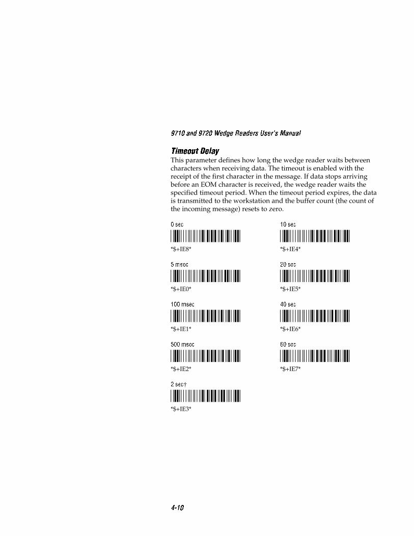
9710 and 9720 Wedge Readers User�s Manual
4-10
Timeout DelayThis parameter defines how long the wedge reader waits betweencharacters when receiving data. The timeout is enabled with thereceipt of the first character in the message. If data stops arrivingbefore an EOM character is received, the wedge reader waits thespecified timeout period. When the timeout period expires, the datais transmitted to the workstation and the buffer count (the count ofthe incoming message) resets to zero.
0 sec
*$+IE8**$+IE8*
10 sec
*$+IE4**$+IE4*
5 msec
*$+IE0**$+IE0*
20 sec
*$+IE5**$+IE5*
100 msec
*$+IE1**$+IE1*
40 sec
*$+IE6**$+IE6*
500 msec
*$+IE2**$+IE2*
60 sec
*$+IE7**$+IE7*
2 sec†
*$+IE3**$+IE3*

Configuring the 9720 Serial Port
4-11
4EchoThis parameter echoes any data sent to the serial port back to thedevice that is transmitting data (normally not used).
Disabled†
*$+IM0**$+IM0*
Enabled
*$+IM1**$+IM1*
Flow ControlThis parameter controls the data transmission for the serial port. Thewedge reader is a DCE device.
Clear to Send/Request to Send (CTS/RTS) is a hardware signal flowcontrol. The reader checks RTS before transmission of each character.The reader uses CTS to control incoming data flow.
XON/XOFF response specifies that the wedge reader responds toXON/XOFF characters received while transmitting. XON/XOFFcontrol specifies that XON/XOFF characters are transmitted by thewedge reader to control data flow. XON/XOFF response and controlspecifies the wedge reader responds to and transmits XON/XOFFcharacters.
None
*$+IL0**$+IL0*
XON/XOFF Control†
*$+IL3**$+IL3*
CTS/RTS Checking and Control
*$+IL1**$+IL1*
XON/XOFF Response and Control
*$+IL4**$+IL4*
XON/XOFF Response
*$+IL2**$+IL2*

9710 and 9720 Wedge Readers User�s Manual
4-12
RXEOMThis parameter defines the receive end of message (RXEOM) for theserial port. An EOM is sent by the portable reader/scale to indicatethe end of a data record. The wedge reader strips the EOM beforetransmitting data to the workstation. Carriage Return Line Feed(<CR><LF>) is the default configuration.
Note: If you are using quotes (") in your data string, refer to the note onpage 3-15.
Disabled
*$+PJ**$+PJ*
To define the RXEOM
1. Scan this bar code.
Accumulate/Change Config/RXEOM
*+/$+PJ**+/$+PJ*
2. Scan this bar code.
Beginning of Data
*/B**"*
3. Scan 1 to 2 characters on the full ASCII chart to build the RXEOM.
4. Scan this bar code.
End of Data
*/B**"*

Configuring the 9720 Serial Port
4-13
45. Scan this bar code.
Exit Accumulate
*-/**-/*
TXEOMThis parameter defines the transmit end of message (TXEOM) for theserial port. The serial port sends an EOM to indicate the end of a datarecord when transmitting data from the reader. Carriage Return LineFeed (<CR><LF>) is the default setting.
Note: If you are using quotes (") in your data string, refer to the note onpage 3-15.
Disabled
*$+PI**$+PI*
To define TXEOM
1. Scan this bar code.
Accumulate/Change Config/TXEOM
*+/$+PI**+/$+PI*
2. Scan this bar code.
Beginning of Data
*/B**"*
3. Scan 1 to 2 characters on the full ASCII chart to build the TXEOM.

9710 and 9720 Wedge Readers User�s Manual
4-14
4. Scan this bar code.
End of Data
*/B**"*
5. Scan this bar code.
Exit Accumulate
*-/**-/*
Solicitation MessageThis parameter defines the solicitation message for the serial port.The message can be sent from the wedge reader to the portablereader or scale at any time by scanning the transmit messagecommand. The solicitation message commands the portablereader/scale to transmit data through the RS-232 interface to thewedge reader. Your scale service manual or portable reader user’smanual contains a list of such commands with the ASCII characterequivalents.
Solicitation messages are stored in EEPROM and remain defineduntil you change them.
Note: If you are using quotes (") in your data string, refer to the note onpage 3-15.
Solicitation Message Cleared†
*$+WS**$+WS*

Configuring the 9720 Serial Port
4-15
4To define the solicitation message
1. Scan this bar code.
Accumulate/Change Config/Solicitation Message
*+/$+WS**+/$+WS*
2. Scan this bar code.
Beginning of Data
*/B**"*
3. Scan 1 to 15 characters using the bar codes on the full ASCII chartto build the solicitation message.
4. Scan this bar code.
End of Data
*/B**"*
5. Scan this bar code.
Exit Accumulate
*-/**-/*

9710 and 9720 Wedge Readers User�s Manual
4-16
Example: Defining a Solicitation Message
The following example describes how to define a solicitation messagefor the portable reader.
1. Scan this bar code to configue a solicitation message.
Accumulate/Change Config/Solicitation Message
*+/$+WS**+/$+WS*
2. Scan this bar code to define the solicitation message.
Beginning of Data
*/B**"*
3. Scan the following bar codes on the full ASCII chart at the end ofthis manual: % % A <CR> <LF>.
<CR> is the CR bar code and <LF> is the LF bar code on the fullASCII chart. The % % characters tell the reader to transmit data.The A character specifies the file name. <CR><LF> are the EOMcharacters.
4. Scan this bar code to end the configuration of the solicitationmessage.
End of Data
*/B**"*
5. Scan this bar code to exit the accumulate feature and modify theconfiguration.
Exit Accumulate
*-/**-/*
When the solicitation message is transmitted to the portable reader,the portable reader begins transmitting File A.

Data Edit Application
5


Data Edit Application
5-3
5This chapter provides information on using the Data Edit application for
stripping specific characters from a data record.
Running Data Edit
Note: The information in this chapter does not apply to the 9710X01Wedge Reader. To verify the type of reader you are using, look at the label onthe base of the reader for a number similar to 9710X02. This numberspecifies the following information: (1) the reader type (9710 or 9720), (2)the revision letter (E, F, G, etc.), and (3) the version number (01 or 02).
With Data Edit running, the reader can:
• Search the incoming data record for the pre-defined data.
• Strip control characters, status words, or checksums from the datarecord.
• Strip characters from the beginning and/or end of a data record.
Using Data Edit Configuration Parameters
You can configure the reader to manipulate data from a scanner, theserial port, or both at the same time. The Window and Data Sourceparameters define the source of the data and Data Identifier, DataBegin, and Data End define how to modify the data.
You can run Data Edit upon power-on, in place of StandardOperation mode, or you can run Data Edit by scanning the RunProgram command.
Application Program
This parameter determines the application that is run on power-up:Standard Operation or Data Edit. If you configure the reader for DataEdit, the reader resets before running Data Edit. To return toStandard Operation, scan the Standard Operation bar code.
Standard Operation†
*$+GA0**$+GA0*
Data Edit
*$+GA1**$+GA1*

9710 and 9720 Wedge Readers User�s Manual
5-4
If you want to run Data Edit temporarily, scan the Run Programcommand.
Run Program
*//**//*
Note: You need to configure the reader before scanning the Run Programcommand. Any type of reset (for example, scanning the reset command orconfiguring a parameter) exits Data Edit and returns the reader to StandardOperation.
The following parameters define the data source (scanner or serialport) and the characters to strip from data records that the readerreceives. You can configure these parameters running StandardOperation or Data Edit, but the parameters only function when theData Edit application is running.
WindowThis parameter defines the source of the data records. Use Windowto strip a specified number of characters from the beginning and endof a data record. Window is run before the Data Identifier parameter.
Window Disabled
*$+WH0**$+WH0*
Window Serial Port Data†
*$+WH2**$+WH2*
Window Scanner Data
*$+WH1**$+WH1*
Window Scanner and Serial Port Data
*$+WH3**$+WH3*

Data Edit Application
5-5
5Data Begin and Data EndThese parameters strip characters from data records the readerreceives. For example, these parameters are useful when you use theWindow parameter for a scale connected to the reader serial port.Scales send several types of information, such as count, weight, anddata that typically goes to a printer. As a result, the data recordscontain non-printing control characters as well as data. ConfigureData Begin and Data End to strip these non-printing controlcharacters from the data record before sending the data to theworkstation.
Data Begin This parameter defines the number of characters that arestripped from the beginning of a data record. The characters arestripped before the addition of preambles and the information is sentto the workstation. This parameter is typically used with scales.
No Stripping†
*$+WB0**$+WB0*
To strip characters from the beginning of the data record
1. Scan this bar code.
Accumulate/Change Config/Data Begin
*+/$+WB**+/$+WB*
2. Scan a number between 1 and 99.
*1**1*
*2**2*
*3**3*
*4**4*
*5**5*
*6**6*
*7**7*
*8**8*
*9**9*
*0**0*

9710 and 9720 Wedge Readers User�s Manual
5-6
3. Scan this bar code.
Exit Accumulate
*-/**-/*
Data End This parameter defines the number of characters that arestripped from the end of a data record. The characters are strippedbefore the addition of postambles and the information is sent to theworkstation.
No Stripping†
*$+WE0**$+WE0*
To strip characters from the end of the data record
1. Scan this bar code.
Accumulate/Change Config/Data End
*+/$+WE**+/$+WE*
2. Scan the number of characters, betwen 1 and 99, you want to strip.
*1**1*
*2**2*
*3**3*
*4**4*
*5**5*
*6**6*
*7**7*
*8**8*
*9**9*
*0**0*
3. Scan this bar code.
Exit Accumulate
*-/**-/*

Data Edit Application
5-7
5Data Source
This parameter defines the source of the data records. Data Source isused with Data Identifier which searches for a set pattern in the datarecord and passes the data record or strips the pattern before passingthe data record.
Note: Window takes precedence over Data Source.
Data Source Disabled
*$+DH0**$+DH0*
Data Source Serial Port Data
*$+DH2**$+DH2*
Data Source Scanner Data†
*$+DH1**$+DH1*
Data Source Scanner and Serial Port Data
*$+DH3**$+DH3*
Data Identifier
This parameter defines the pattern that the reader searches for in adata record and how to process the data. The pattern can be a space,an alpha character, or a user-defined pattern. The reader can strip thepattern, pass the data record unmodified, or reject the data record ifthe pattern is not found.
Disable†
*$+DI0**$+DI0*

9710 and 9720 Wedge Readers User�s Manual
5-8
To define the data identifier
1. Scan this bar code.
Accumulate/Change Config/Data Identifier
*+/$+DI**+/$+DI*
2. Scan one of the bar codes below to define the data identifierpattern.
Pattern 1 A space in positions 2 through 5 of a data recorddefines a pattern of all characters up to and including the firstspace.
*1**1*
For example, there are two data records: 12 345 and A 3 45. Thepattern for the first data record is 1, 2 and the space. The patternfor the second data record is A and the space.
Pattern 2 An alpha character in position 1 through 4 of a datarecord defines a pattern of all characters up to and including thefirst alpha character. (A space immediately following the alphacharacter is included.)
*2**2*
For example, there are two data records: 12ABC and A 3B45. Thepattern for the first data record is 1, 2 and A. The pattern for thesecond data record is A and the space.
Pattern 3 This pattern is user-defined and stored in readermemory. Refer to the next section, “User-Defined Pattern,” forinformation on creating and using a user-defined pattern.
*3**3*

Data Edit Application
5-9
53. Scan one of the bar codes below to define data handling:
• Pattern present—strip pattern and transmit data. Pattern notpresent—reject data record.
*0**0*
• Pattern present—transmit data record unmodified. Pattern notpresent—reject data record.
*1**1*
• Pattern present—strip pattern and transmit data. Pattern notpresent—transmit data record unmodified.
*2**2*
4. Scan this bar code.
Exit Accumulate
*-/**-/*
User-Defined Pattern
This parameter defines a pattern to find in the data record. Readermemory has space for up to 32 patterns, with a maximum of 5characters in each pattern. The characters can be numeric, uppercasealpha, or wild card characters @, #, and ?.
Wild card characters represent a character type:
@ is any uppercase alpha character.
# is any numeric character.
? is any character.

9710 and 9720 Wedge Readers User�s Manual
5-10
To delete the user-defined patterns from memory, you must scan theDefault Configuration command listed in Chapter 2.
Note: If you are using quotes (") in your data string, refer to the note onpage 3-15.
To define a pattern
1. Scan this bar code.
Accumulate/Change Config/User-defined Pattern
*+/$+DI4**+/$+DI4*
2. Scan this bar code.
Beginning of Data
*/B**"*
3. Scan 1 to 5 characters from the full ASCII chart. The characterscan be numeric, uppercase alpha, @, #, or ?.
4. Scan this bar code.
End of Data
*/B**"*
5. Scan this bar code.
Exit Accumulate
*-/**-/*

Data Edit Application
5-11
5Example: Applying a User-Defined Pattern
This example defines a user-defined pattern consisting of a capital A,a numeric character, and a character of any type, and explains how toconfigure the reader to manipulate the data.
Note: You must configure the reader for the correct data source and runData Edit for Data Identifier and User-Defined Pattern parameters tofunction.
1. Scan this bar code to configure the user-defined pattern:
Accumulate/Change Config/User-defined Pattern
*+/$+DI4**+/$+DI4*
2. Scan this bar code.
Beginning of Data
*/B**"*
3. Scan A, # and ? from the full ASCII chart at the end of thismanual.
4. Scan this bar code.
End of Data
*/B**"*
5. Scan this bar code to exit the accumulate feature and modify theconfiguration.
Exit Accumulate
*-/**-/*

9710 and 9720 Wedge Readers User�s Manual
5-12
You have configured a user-defined pattern. Next, you will apply theuser-defined pattern for stripping characters from a data record.
6. Scan this bar code to configure the data identifier:
Accumulate/Change Config/Data Identifier
*+/$+DI**+/$+DI*
7. Scan this bar code to use the pattern stored in reader memory:
Pattern 3 (User-Defined)
*3**3*
8. Scan this bar code to find a user-defined pattern in the datarecord:
Strip Pattern and Transmit Data
*2**2*
9. Scan this bar code to exit the accumulate feature and modify theconfiguration.
Exit Accumulate
*-/**-/*
When you scan data, the reader strips the pattern consisting of an A,a numeric character, and another character and transmits theremaining data to the workstation. If the pattern is not found in thedata string, the reader transmits the data unmodified.

Specifications
A


Specifications
A-3
AMechanical Specifications
Dimensions: Length: 6.6 inches (184 mm)
Width: 4.4 inches (112 mm)
Height: 1.1 inches (28 mm)
Weight: 7 ounces (200 grams)
Environmental Specifications
Operating Temperature: +32° to +122°F (0° to +50°C)
Storage Temperature: -4° to +158°F (-20° to +70°C)
Humidity: 10% to 90% non-condensing
Keyboard Equivalent Tables
The following tables list the ASCII equivalent for thePC/workstation, twinax/coax terminal, and ASCII terminalkeyboard keystrokes. The alpha characters and numeric charactersare standard for all three tables (keystroke A’s ASCII equivalent is A,keystroke 1’s ASCII equivalent is 1, etc.); therefore, they are not listedin the tables. Refer to the tables when customizing your keyboardas described in Chapter 3.

9710 and 9720 Wedge Reader User�s Manual
A-4
PC/Workstation Keyboard MappingA PC is a personal computer; it is a stand-alone unit which does notneed to be connected to a host in order to operate.
ASCII Char. Keystroke ASCII Char. Keystroke
NUL Num + SP SpacebarSOH Num Lock ! !STX Scroll Lock " (quote) "( quote)ETX - # #EOT Ins $ $ENQ Del % %ACK Sys Req & &BEL N/A ' (apostrophe) ' (apostrophe)BS ← Alt GR ( (HT → (tab) ) )LF Caps Lock * *VT ← (tab) + +FF Alt , (comma) , (comma)CR ↵ (Enter) - (dash) - (dash)SO Ctrl . (period) . (period)SI ↑ (shift) / /DLE F1 : :DC1 F2 ; ;DC2 F3 < <DC3 F4 = =DC4 F5 > >NAK F6 ? ?SYN F7 @ @ETB F8 [ [CAN F9 \ \EM F10 ] ]SUB Home ^ ^ESC Esc _ (underline) _ (underline)FS PgUp ` (accent) ` (accent)GS PgDn { ↑RS PrtSc | ↓US End } ←DEL ← (bksp del) ~ «

Specifications
A-5
ATwinax/Coax Terminal Keyboard MappingA twinax/coax terminal connects to the host using a cable with atwinax/coax connector.
ASCII Char. Keystroke ASCII Char. Keystroke
NUL CMD/PF17 SP SpaceSOH CMD/PF18 ! !STX CMD/PF19 " (quote) " (quote)ETX CMD/PF20 # #EOT CMD/PF21 $ $ENQ CMD/PF22 % %ACK CMD/PF23 & &BEL CMD/PF24 ' (apostrophe) ' (apostrophe)BS Field +/PA1 ( (HT → (tab) ) )LF ↵ (Enter) * *VT ← (tab) + +FF Alt/Cmd , (comma) , (comma)CR CR - (dash) - (dash)SO Field Exit/PA2 . (period) . (period)SI ↑ (shift) / /DLE CMD/PF1 : :DC1 CMD/PF2 ; ;DC2 CMD/PF3 < <DC3 CMD/PF4 = =DC4 CMD/PF5 > >NAK CMD/PF6 [ ↑SYN CMD/PF7 \ \ETB CMD/PF8 ] ↓CAN CMD/PF9 ^ PlayEM CMD/PF10 _ (underline) _ (underline)SUB CMD/PF11 ` (accent) ` (accent)ESC CMD/PF12 { AttnFS CMD/PF13 | Erase/Input/EOFGS CMD/PF14 } Rst, Error/RstRS CMD/PF15 ~ DupUS CMD/PF16 DEL ← (bksp del)

9710 and 9720 Wedge Reader User�s Manual
A-6
ASCII Terminal Keyboard MappingAn ASCII terminal sends ASCII characters to the host.
ASCII Char. Keystroke ASCII Char. Keystroke
NUL F1 SP SpacebarSOH F2 ! !STX F3 " (quote) " (quote)ETX F4 # #EOT F5 $ $ENQ F6 % %ACK F7 & &BEL F8 ' (apostrophe) ' (apostrophe)BS F12 ( (HT → (tab) ) )LF ↵ (Enter) * *VT ← (tab) + +FF Ctrl , (comma) , (comma)CR CR - (dash) - (dash)SO Lock . (period) . (period)SI ↑ (shift) / /DLE F10 : :DC1 F14 ; ;DC2 Help < <DC3 DO = =DC4 Select > >NAK F18 ? ?SYN F19/Left Alt @ @ETB F20/Right Alt] [ [CAN Compose Char \ \EM Prev Screen ]SUB Next Screen ^ ^ESC F11 _ (underline) _ (underline)FS PF1 ` (accent) ` (accent)GS PF2 { ↑RS PF3 | ↓US PF4 } ←DEL delete ~ «

Specifications
A-7
AASCII Characters Table
The following table lists the ASCII characters and their binary,hexadecimal, and CODE 39 equivalent. Refer to this table whendisplaying the default ASCII keycode equivalent for your keyboard(see Chapter 3).
Binary0
00000000000000010000001000000011
0000010000000101000001100000011100001000000010010000101000001011
0000110000001101000011100000111100010000000100010001001000010011
0001010000010101000101100001011100011000000110010001101000011011
0001110000011101000111100001111100100000001000010010001000100011
0010010000100101001001100010011100101000001010010010101000101011
0010110000101101001011100010111100110000001100010011001000110011
0011010000110101001101100011011100111000001110010011101000111011
00111100001111010011111000111111
FULL ASCIIHex1
00010203
0405060708090A0B
0C0D0E0F10111213
1415161718191A1B
1C1D1E1F20212223
2425262728292A2B
2C2D2E2F30313233
3435363738393A3B
3C3D3E3F
Dec2
00010203
0405060708091011
1213141516171819
2021222324252627
2829303132333435
3637383940414243
4445464748495051
5253545556575859
60616263
C393
%U$A$B$C
$D$E$F$G$H$I$J$K
$L$M$N$O$P$Q$R$S
$T$U$V$W$X$Y$Z%A
%B%C%D%ESP/A/B/C
/D/E/F/G/H/I/J/K
/L/M/N/O/P7
/Q/R/S
/T/U/V/W/X/Y/Z%F
%G%H%I%J
Char4
NULSOHSTXETX
EOTENQACKBELBSHTLFVT
FFCRSOSIDLEDC1DC2DC3
DC4NAKSYNETBCANEMSUBESC
FSGSRSUSSP6
!"#
$%&’()*+
,-./0123
456789:;
<=>?
Binary
01000000010000010100001001000011
0100010001000101010001100100011101001000010010010100101001001011
0100110001001101010011100100111101010000010100010101001001010011
0101010001010101010101100101011101011000010110010101101001011011
0101110001011101010111100101111101100000011000010110001001100011
0110010001100101011001100110011101101000011010010110101001101011
0110110001101101011011100110111101110000011100010111001001110011
0111010001110101011101100111011101111000011110010111101001111011
01111100011111010111111001111111
Hex
40414243
4445464748494A4B
4C4D4E4F50515253
5455565758595A5B
5C5D5E5F60616263
6465666768696A6B
6C6D6E6F70717273
7475767778797A7B
7C7D7E7F
Dec
64656667
6869707172737475
7677787980818283
8485868788899091
9293949596979899
100101102103104105106107
108109110111112113114115
116117118119120121122123
124125126127
C39
%VABC
DEFGHIJK
LMNOPQRS
TUVWXYZ%K
%L%M%N%O%W+A+B+C
+D+E+F+G+H+I+J+K
+L+M+N+O+P+Q+R+S
+T+U+V+W+X+Y+Z%P
%Q%R%S%T8
Char
@ABC
DEFGHIJK
LMNOPQRS
TUVWXYZ[
\]^_‘abc
defghijk
lmnopqrs
tuvwxyz{
|}~
9
Control
NULSOHSTXETX
EOTENQACKBELBSHTLFVT
FFCRSOSIDLEDC1DC2DC3
DC4NAKSYNETBCANEMSUBESC
FSGSRSUSSPDEL
Character Definitions5
Null, or all zeroesStart of HeadingStart of TextEnd of Text
End of TransmissionEnquiryAcknowledgementBellBackspaceHorizontal TabLine FeedVertical Tab
Form FeedCarriage ReturnShift OutShift InData Link EscapeDevice Control 1 (XON)Device Control 2Device Control 3 (XOFF)
Device ControlNegative AcknowledgeSyncronous IdleEnd Transmission BlockCancelEnd of MediumSubstituteEscape
File SeparatorGroup SeparatorRecord SeparatorUnit SeparatorSpaceDelete
Notes
ASCI7x10


Glossary
G


Glossary
G-3
G2 of 5 CodeA bar code symbology that is fixed length, discrete, and self-checking. It requires loose printing tolerances. It is used forwarehouse sorting systems, photofinishing envelopes, andsequentially numbered airline tickets. The character set is 0 - 9. Themaximum density is 7.7 characters per inch.
Accumulate ModeOperating mode in which the reader stores scanned information inthe buffer until a transmit command is received.
AlphanumericA set that contains letters, numbers, and usually other characterssuch as punctuation marks.
ASCIIThe acronym for American Standard Code for InformationInterchange. A standard seven bit code almost always transmittedwith a parity bit for a total of eight bits per character. ASCII wasestablished by the American National Standards Institute to achievecompatibility between various types of data communicationequipment. ASCII is the most commonly used code for non-IBMequipment.
BarIn bar code symbology, it refers to the darker element of a printedbar code symbol.
Bar CodeAn automatic identification technology which encodes informationinto an array of varying width parallel rectangular bars and spaces.
BufferAn area of storage used to hold data being transferred from onedevice to another.

9710 and 9720 Wedge Readers User�s Manual
G-4
Character SetRefers to specific letters, numerals, and symbols that support aparticular language (French, US, ASCII).
Check DigitA character included in a bar code whose value is used to do amathematical check on the value of the decoded bar code to retainaccuracy.
CodabarA bar code symbology that is variable length, discrete, and self-checking. It requires close printing tolerances. It is used indepartment store price labeling, libraries, medicine, photofinishingenvelopes, air bills, and American Blood Commission blood tags. Thecharacter set is 0 - 9, dollar sign ($), colon (:), period (.), slash (/), plus(+), and minus (-). Its maximum density is 12.8 characters per inch.
Code 11A bar code symbology that is variable length, discrete, and not self-checking. It requires moderate printing tolerances and one or twocheck digits. It is widely used in labeling telecommunicationsequipment. The character set is 0 - 9 and minus (-). Its maximumdensity is 15 characters per inch.
Code 128A bar code symbology that is variable length, continuous, andweakly self-checking code. It requires loose printing tolerances. Itshigh density makes it useful when printing data in a limited space.The character set is all 128 ASCII characters. Its maximum density is12.1 alphanumeric characters per inch or 24.2 numeric characters perinch.
Code 16KA bar code symbology that is a multi-row, continuous code that hasloose printing tolerances. It requires a check digit and the characterset includes all 128 ASCII characters. This symbology is suitable forlabeling small objects because it can encode more data in less areathan many other codes.

Glossary
G-5
GCode 39A bar code symbology that is discrete, variable length, and self-checking. It requires loose printing tolerances. It is used inmanufacturing, government agencies, and health care. The characterset is A - Z uppercase, 0 - 9, dollar sign ($), period (.), slash (/),percent (%), space ( ), plus (+), and minus (-). It can be extended tofull 128 character ASCII by use of a two-character encoding scheme(see Full ASCII). Its maximum density is 9.8 characters per inch.
Code 49A bar code symbology that is multi-row, fixed length, andcontinuous. It requires loose printing tolerances. It is suitable forlabeling small objects because in can encode more data in less areathan other codes. The character set is all 128 ASCII characters. Itsmaximum density is 93.3 alphanumeric characters per inch or 154.3numeric characters per inch.
Code 93A bar code symbology that is discrete, variable length, and self-checking. It requires loose printing tolerances. It can be usedinterchangeably with Code 39 when higher density printing isrequired. The character set is the same as Code 39: A - Z uppercase, 0- 9, dollar sign ($), period (.), slash (/), percent (%), space ( ), plus (+),and minus (-). It can be extended to full 128 character ASCII by use ofa four-character encoding scheme (see Full ASCII). Its maximumdensity is 14.8 characters per inch.
Concatenated CodeTwo bar codes that are read into one data record.
ConfigurationThe settings that determine the operating characteristics of thereader.
Continuous CodeCharacteristics of a bar code symbology where all spaces within thesymbol are parts of characters. There is no intercharacter gap in acontinuous code. It is the opposite of discrete.

9710 and 9720 Wedge Readers User�s Manual
G-6
Clear to Send/Request to Send (CTS/RTS)A type of hardware flow control. The 9720 reader signals the serialport device when the reader is ready to receive data (CTS). The 9720reader checks with the serial port device when the reader is ready tosend data (RTS).
Data Begin/Data EndTwo Data Edit parameters that strip a set number of characters fromthe beginning and end of incoming data. You use this parameter withthe Window parameter.
Data IdentifierA Data Edit parameter that searches incoming data for a predefinedpattern to strip the pattern, reject the data containing the pattern, oraccept the data containing the pattern. You use the parameter withthe Data Source parameter.
Data SourceA Data Edit parameter that defines the source of the data:wand/scanner, serial port, or both. You use this parameter with theData Identifier parameter.
Discrete CodeCharacteristic of a bar code symbology in which the intercharactergap is not part of the code and is allowed to vary dimensionallywithin wide tolerance limits. Opposite of continuous.
EchoA communications parameter that configures the 9720 reader torepeat to the serial port data received by the serial port.
EOMEnd of message character. Typically it is a carriage return or a linefeed.
Fixed LengthCharacteristic of a bar code symbology in which the number ofcharacters per symbol is predetermined. Opposite of variable length.

Glossary
G-7
GFlow ControlA method for controlling the flow of data between the reader and the9720 serial port. It stops the transmitting device from sending datawhen the receiving device buffer fills up and starts it again when thebuffer empties. This can be done through software (XON/XOFF) orhardware (CTS/RTS).
Full ASCIIAn operating mode that sets the reader to properly decode Code 39or Code 93 labels containing data that may include any of the 128ASCII characters.
HIBCHealth Industry Bar Code standard. It uses Code 39 symbology andspecifies the format of the data.
Human-ReadableA character, number, or symbol printed in a font that can be read bya human; as opposed to bar code symbology that can only be read bya machine.
Input DeviceA wand or laser scanner that scans bar code information into thereader.
Intercharacter DelayA communication parameter that causes the reader to delay a settime between characters when sending data to the workstation.
Intercharacter GapThe space between the last element of one character and the firstelement of the adjacent character of a discrete bar code symbol.

9710 and 9720 Wedge Readers User�s Manual
G-8
Interleaved 2 of 5 CodeA bar code symbology that is fixed length (it requires an evennumber of characters), continuous, and self-checking. It requiresloose printing tolerances. It is used in warehousing, heavy industry,the automotive industry, and UPC standard shipping labels. Thecharacter set is 0 - 9. Its maximum density is 18 numeric charactersper inch.
ISBT 128 CodeThis bar code symbology is a variation of Code 128. It was developedby the International Society of Blood Transfusion (ISBT) for the barcode labeling of whole blood and blood products. This symbologysupports concatenation (linking) of two ISBT 128 bar codes. Pairs ofconcatenated ISBT 128 bar codes can be decoded from a single scanof a laser scanner or wand.
Keyboard EquivalentThe keycode sent by the keyboard to the workstation representingthe pressed key. The reader has a table of ASCII characters thatcorrespond to the keys on the keyboard. When an ASCII character isscanned, the reader transmits the keycode to the workstation.
Label FormatThe design of a bar code label; the arrangement of the text, lines andbar codes on a label.
MSI CodeA bar code symbology that is a modified version of Plessey code. It isfixed length, continuous, and non self-checking. This code is used tomark retail shelves for inventory reordering. The character set is 0 - 9plus additional symbols.
Multiple-Read Bar CodeRefers to a bar code that takes the form: start code space data stopcode. Multiple-read bar codes are stored in the reader’s buffer until acommand to transmit is received or until a regular bar code (a barcode with no leading space) is scanned. See regular label.
ParametersThe operating limits of the reader.

Glossary
G-9
GPlessey CodeA bar code symbology that is fixed length, continuous, and not self-checking. It is used extensively in libraries. The character set is 0 - 9plus six additional symbols.

9710 and 9720 Wedge Readers User�s Manual
G-10
PreamblePredefined data that is automatically appended to the beginning oftransmitted data.
PostamblePredefined data that is automatically appended to the end oftransmitted data.
Regular Bar CodeRefers to a bar code that takes the form: start code data stop code.Regular bar codes are transmitted as soon as they are scanned. Seemultiple-read bar code.
RS-232Widely recognized protocol standard for serial binary datainterchange. The standard covers the physical, electrical, andfunctional characteristics of the interface.
ScannerAn electronic device that converts printed bar code into electricalsignals.
Scanner Trigger ModeA parameter that allows you to decide between pulling the triggerevery time you want to scan labels or pulling the trigger and havingthe scanner remain on for a set amount of time.
Scanner ModeA parameter that allows you to decide between pulling the triggerevery time you want to scan a label or pulling the trigger to scanmany labels.
Scanner TimeoutA parameter that lets you set the amount of time a scanner remainson after the trigger is pulled.

Glossary
G-11
GSelf-CheckingCharacteristic of a bar code symbology that, without the use of acheck digit, allows the bar code to be decoded without an error.
Self-TestThe search for malfunctions in the electrical or mechanical systems ofa device by its own actions.
SerialA communication scheme in which the bits of a byte are transferredone-at-a-time.
Solicitation MessageA predefined message sent by the wedge reader to initiate datatransmission from the device connected to the wedge reader serialport.
SpaceThe lighter element of a bar code usually formed by the backgroundbetween bars.
Start and Stop CharactersSpecified characters at the beginning and end of a bar code symbolthat provides “direction of read” information to the reader decodinglogic.
SymbologyA scheme for encoding data as bar code. Code 39, Interleaved 2 of 5,and Codabar are examples of different symbologies.
Timeout DelayThe specified time the reader waits between receiving charactersfrom the serial port, before transmitting the data already receivedonto the workstation (if no EOM is received).
Quiet ZoneThe area immediately preceding the start character and following thestop character that contains no markings. This area is usually tentimes the width of the narrow bar.

9710 and 9720 Wedge Readers User�s Manual
G-12
UPC/EAN CodeUniversal Product Code (UPC) is a subset of the European ArticleNumbering (EAN). The EAN code is also referred to as WorldProduct Code (WPC) and International Article Numbering (IAN). Itis used in marking items for retail sale. This code is fixed length,continuous, and weakly self-checking. It requires close printingtolerances. The character set is 0 - 9. Its maximum character density is13.8 numeric characters per inch.
Variable LengthA type of symbology in which the number of characters per symbol isnot restricted. It is opposite of fixed length.
VotingA laser scanner parameter that takes more than one (low setting) ormore than two (high setting) matching scans from the same label toyield a good read. This is useful when scanning poor quality labelsthat may cause substitution errors. This is for laser scanning only.
Wait CharacterA predefined character that delays the reader a set time (wait time)before the reader sends the next set of data to the workstation.
WindowA Data Edit parameter that delays the reader a set time (wait time),before sending the next set of data to the workstation.
XON/XOFFA type of software flow control for communication between digitaldevices. It stops the host from sending data when the device bufferfills up (XOFF) and starts it again when the buffer empties (XON).

Index
I


Index
I-3
INumbers
2 of 5 Code, 3-372 of 5 Code configuration
example, 3-38
A
American Blood Commission(ABC) Codabar, 3-34
Application Program, 5-3ASCII
characters table, A-7keycode customization, 3-45keycode equivalent example,
3-46terminal keyboard mapping,
A-6Automobile Industry Action
Group (AIAG), 3-24
B
Backspace command, 2-5bar code symbologies, 3-24
2 of 5 Code, 3-37Codabar, 3-34Code 11, 3-24Code 39, 3-24Code 49, 3-29Code 93, 3-30Code 128, 3-31Code 16K, 3-33Interleaved 2 of 5, 3-36ISBT 128, 3-31MSI Code, 3-39Plessey Code, 3-39UPC/EAN, 3-41
bar codesmultiple-read, 2-4regular, 2-4
Baud Rate parameter, 4-8Beeper Volume parameter, 3-6
C
cables, 1-4Caps Lock parameter, 3-6
Change Configuration command,2-5
checking communications, 1-10checking connections, 1-8Clear command, 2-5Clear to Send, 4-11Codabar, 3-34Codabar configuration example,
3-35Code 11, 3-24Code 39, 3-24Code 39 configuration example,
3-28Code 49, 3-29Code 93, 3-30Code 128, 3-31Code 16K, 3-33Command Processing parameter,
3-7command string, 2-5commands
Backspace, 2-5Change Configuration, 2-5Clear, 2-5Default Configuration, 2-6disabling, 3-7enabling, 3-7Enter, 2-6Enter Accumulate, 2-6Exit Accumulate, 2-7Reset, 2-7Transmit Message, 2-7
communications, checking, 1-10concatenate
Codabar, 3-35ISBT 128, 3-31
configurationnull, 1-9parameters, 3-6
connectingpower supply, 1-7wand or scanner, 1-6
customizing ASCII keycodeequivalents, 3-45

9710 and 9720 Wedge Readers User's Manual
I-4
D
Data Begin parameter, 5-5Data Bits parameter, 4-9Data Edit parameters
Application Program, 5-3Data Begin, 5-5Data End, 5-6Data Identifier, 5-7Data Source, 5-7User-Defined Pattern, 5-9Window, 5-4
Data End parameter, 5-6Data Entry keyboards, 3-7Data Identifier parameter, 5-7Data Redirection parameter, 3-10Data Source parameter, 5-7Default Configuration command,
2-6Default Configuration bar code,
3-5default workstation
configuration, 1-9disabling commands, 3-7
E
Echo, 4-11enabling commands, 3-7Enter Accumulate command, 2-6Enter command, 2-6European Article Numbering
Code (EAN), 3-41examples
applying user-defined pattern,5-11
ASCII keycode equivalent,3-46
2 of 5 Code definition, 3-38Codabar definition, 3-35Code 39 definition, 3-28disabling/enabling reader
commands, 3-7keyboard modification, 3-48MSI Code definition, 3-40postamble definition, 3-20preamble A definition, 3-18
solicitation message definition,4-16
UPC/EAN definition, 3-43wait configuration, 3-13
Exit Accumulate command, 2-7
F
Flow Control parameter, 4-11full ASCII mode, 3-25
H
headphone/speaker jack, 2-8Health Industry Bar Code
(HIBC), 3-24
I
installation, preparing, 1-3Intercharacter Delay parameter,
3-15Interleaved 2 of 5 Code, 3-36ISBT 128, 3-31
K
keyboard equivalent tables, A-3keyboard modification example,
3-48
M
mixed-full ASCII, 3-26modifying keyboard example,
3-48mounting the reader, 1-11MSI Code, 3-39MSI Code configuration example,
3-40multiple-read bar codes, 2-4
N
non-full ASCII mode, 3-25null configuration, 1-9
O
operating statesstandard, 2-4test and service, 2-3

Index
I-5
IP
Parity parameter, 4-8PC/workstation keyboard
mapping, A-4pin assignments, 9720 serial port
connector, 4-4Plessey Code, 3-39portable reader
connecting to 9720, 4-4uploading data to 9720, 4-6
postambleexample, 3-20parameter, 3-19
powerapplying, 1-9requirements, 1-7
power supplyconnecting, 1-7types, 1-7
preambleexample, 3-18parameter, 3-15
Q
quotes ("), using in data strings,3-15
R
readercommands, 2-5configuration parameters, 3-6Default Configuration bar
code, 3-5disabling/enabling example,
3-9headphone/speaker jack, 2-8serial port, 2-8, 4-3status beeps, 2-8
reader parametersBeeper Volume, 3-6Caps Lock, 3-6Command Processing, 3-7Data Redirection, 3-10Intercharacter Delay, 3-15Postamble, 3-19
Preamble, 3-15Scanner Mode, 3-21Scanner Timeout, 3-22Scanner Trigger, 3-21Voting, 3-23Wait Character, 3-11Wait Time, 3-12
reader/keyboard cable, 1-4reader/workstation cable, 1-4Reset command, 2-7RXEOM, 4-12
S
scaleuploading data to 9720, 4-7connecting to 9720, 4-5
Scanner Mode parameter, 3-21Scanner Timeout parameter, 3-22Scanner Trigger parameter, 3-21scanner, connecting, 1-6serial port
configuration parameters, 4-3connecting to, 4-3connecting scale to, 4-5connecting portable reader to,
4-4CTS/RTS, 4-11pin assignments, 4-4uploading data from portable
reader, 4-6uploading data from scale, 4-7XON/XOFF, 4-11
serial port parametersBaud Rate, 4-8Data Bits, 4-9Echo, 4-11Flow Control, 4-11Parity, 4-8RXEOM, 4-12Solicitation Message, 4-14Stop Bits, 4-9Timeout Delay, 4-10TXEOM, 4-13
solicitation messageexample, 4-16parameter, 4-14

9710 and 9720 Wedge Readers User's Manual
I-6
standard operation, 2-4status beeps, 2-8Stop Bits parameter, 4-9
T
Timeout Delay parameter, 4-10Transmit Message command, 2-7troubleshooting, 1-11twinax/coax terminal keyboard
mapping, A-5TXEOM, 4-13
U
Universal Product Code (UPC),3-41
UPC/EAN, 3-41UPC/EAN configuration
example, 3-43User-Defined Pattern, 5-9User-Defined Pattern example,
5-11
V
Velcro mounting reader, 1-11Voting, 3-23
W
Wait Character, parameter, 3-11wait configuration example, 3-13Wait Time parameter, 3-12wand, connecting, 1-6Wedge Interface (WIF) guide, 1-4Window parameter, 5-4wood screw mounting reader,
1-12workstation
configuration bar code, 1-9default configuration
command, 3-5null configuration, 1-9identification, 1-9
X
XON/XOFF, 4-11

Full ASCII Bar Code Chart
To correctly scan and interpret full ASCII bar codes, the reader must be inCode 39 Full ASCII or Mixed-full ASCII mode. ACK
*$F*ETX
*$C*VT
*$K*_
*%O*\
*%L*E
*E*U
*U*k
*+K*BEL
*$G*FF
*$L*!
*/A*:
*/Z*Space
*SP*F
*F*V
*V*l
*+L*BS
*$H*FS
*%B*,
*/L*°
*%W*0
*0*G
*G*W
*W*m
*+M*CAN
*$X*GS
*%C*"
*/B*<
*%G*1
*1*H
*H*X
*X*n
*+N*CR
*$M*HT
*$I*-
*/M*|
*%Q*2
*2*I
*I*Y
*Y*o
*+O*DC1
*$Q*LF
*$J*#
*/C*=
*%H*3
*3*J
*J*Z
*Z*p
*+P*DC2
*$R*NAK
*$U*.
*/N*}
*%R*4
*4*K
*K*a
*+A*q
*+Q*DC3
*$S*NUL
*%U*$
*/D*>
*%I*5
*5*L
*L*b
*+B*r
*+R*DC4
*$T*RS
*%D*/
*/O*~
*%S*6
*6*M
*M*c
*+C*s
*+S*DEL
*%T*SI
*$O*%
*/E*?
*%J*7
*7*N
*N*d
*+D*t
*+T*DLE
*$P*SO
*$N*'
*/G*[
*%K*8
*8*O
*O*e
*+E*u
*+U*EM
*$Y*SUB
*$Z**
*/J*@
*%V*9
*9*P
*P*f
*+F*v
*+V*ENQ
*$E*SYN
*$V*(
*/H*&
*/F*A
*A*Q
*Q*g
*+G*w
*+W*EOT
*$D*SOH
*$A*+
*/K*)
*/I*B
*B*R
*R*h
*+H*x
*+X*ESC
*%A*STX
*$B*^
*%N*;
*%F*C
*C*S
*S*i
*+I*y
*+Y*ETB
*$W*US
*%E*]
*%M*{
*%P*D
*D*T
*T*j
*+J*z
*+Z*

Non-Full ASCII Bar Code Chart
To correctly scan and interpret non-full ASCII bar codes, the reader must bein Code 39 Mixed-full ASCII or Non-full ASCII mode.
A
*A*L
*L*W
*W*7
*7*B
*B*M
*M*X
*X*8
*8*C
*C*N
*N*Y
*Y*9
*9*D
*D*O
*O*Z
*Z*+
*/K*E
*E*P
*P*0
*0*-
*/M*F
*F*Q
*Q*1
*1*$
*/D*G
*G*R
*R*2
*2*/
*/O*H
*H*S
*S*3
*3*.
*/N*I
*I*T
*T*4
*4*Space
*SP*J
*J*U
*U*5
*5*%
*/E*K
*K*V
*V*6
*6*