92274 Pedestal Sump Pump - Harbor Freight...
14
1/3 HP PEDESTAL SUMP PUMP ASSEMBLY AND OPERATING INSTRUCTIONS 3491 Mission Oaks Blvd., Camarillo, CA 93011 Visit our Web site at: http://www.harborfreight.com Copyright 2004 by Harbor Freight Tools ® . All rights reserved. No portion of this manual or any artwork contained herein may be reproduced in any shape or form without the express written consent of Harbor Freight Tools. For technical questions, please call 1-800-444-3353. ® © TO PREVENT SERIOUS INJURY, READ AND UNDERSTAND ALL WARNINGS AND INSTRUCTIONS BEFORE USE. Model 92274
-
Upload
vuongnguyet -
Category
Documents
-
view
216 -
download
3
Transcript of 92274 Pedestal Sump Pump - Harbor Freight...

1/3 HP PEDESTAL SUMP PUMP
ASSEMBLY AND OPERATING INSTRUCTIONS
3491 Mission Oaks Blvd., Camarillo, CA 93011Visit our Web site at: http://www.harborfreight.com
Copyright 2004 by Harbor Freight Tools®. All rights reserved. No portion of thismanual or any artwork contained herein may be reproduced in any shape or form
without the express written consent of Harbor Freight Tools.For technical questions, please call 1-800-444-3353.
®
©
TO PREVENT SERIOUS INJURY,READ AND UNDERSTAND ALL WARNINGS
AND INSTRUCTIONS BEFORE USE.
Model 92274
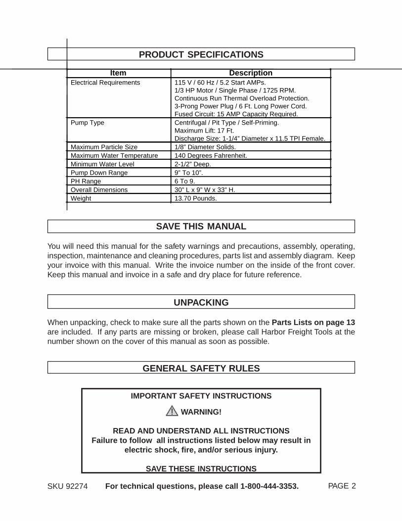
PRODUCT SPECIFICATIONS
SAVE THIS MANUAL
You will need this manual for the safety warnings and precautions, assembly, operating,inspection, maintenance and cleaning procedures, parts list and assembly diagram. Keepyour invoice with this manual. Write the invoice number on the inside of the front cover.Keep this manual and invoice in a safe and dry place for future reference.
GENERAL SAFETY RULES
WARNING!
READ AND UNDERSTAND ALL INSTRUCTIONSFailure to follow all instructions listed below may result in
electric shock, fire, and/or serious injury.
SAVE THESE INSTRUCTIONS
SKU 92274 PAGE 2For technical questions, please call 1-800-444-3353.
UNPACKING
When unpacking, check to make sure all the parts shown on the Parts Lists on page 13are included. If any parts are missing or broken, please call Harbor Freight Tools at thenumber shown on the cover of this manual as soon as possible.
IMPORTANT SAFETY INSTRUCTIONS
Item DescriptionElectrical Requirements 115 V / 60 Hz / 5.2 Start AMPs.
1/3 HP Motor / Single Phase / 1725 RPM.Continuous Run Thermal Overload Protection.3-Prong Power Plug / 6 Ft. Long Power Cord.Fused Circuit: 15 AMP Capacity Required.
Pump Type Centrifugal / Pit Type / Self-Priming.Maximum Lift: 17 Ft.Discharge Size: 1-1/4” Diameter x 11.5 TPI Female.
Maximum Particle Size 1/8” Diameter Solids.Maximum Water Temperature 140 Degrees Fahrenheit.Minimum Water Level 2-1/2” Deep.Pump Down Range 9” To 10”.PH Range 6 To 9.Overall Dimensions 30” L x 9” W x 33” H.Weight 13.70 Pounds.

3. Keep bystanders, children, and visitors away while operating a power tool.Distractions can cause you to lose control.
ELECTRICAL SAFETY
1. Grounded tools must be plugged into an outlet properly installed and groundedin accordance with all codes and ordinances. Never remove the groundingprong or modify the plug in any way. Do not use any adapter plugs. Checkwith a qualified electrician if you are in doubt as to whether the outlet isproperly grounded. If the tool should electrically malfunction or break down,grounding provides a low resistance path to carry electricity away from the user.
2. Avoid body contact with grounded surfaces such as pipes, radiators, ranges,and refrigerators. There is an increased risk of electric shock if your body isgrounded.
3. Do not expose the Motor to rain or wet conditions. Water entering the Motorwill increase the risk of electric shock.
4. Do not abuse the Power Cord. Never use the Power Cord to pull the Plug froman outlet. Keep the Power Cord away from heat, oil, sharp edges, or movingparts. Replace damaged Power Cords immediately. Damaged Power Cordsincrease the risk of electric shock.
5. When operating a power tool outside, use an outdoor extension cord marked“W-A” or “W”. These extension cords are rated for outdoor use, and reduce therisk of electric shock.
PERSONAL SAFETY
1. Stay alert. Watch what you are doing, and use common sense when operatinga power tool. Do not use a power tool while tired or under the influence ofdrugs, alcohol, or medication. A moment of inattention while operating powertools may result in serious personal injury.
SKU 92274 For technical questions, please call 1-800-444-3353. PAGE 3
2. Do not operate power tools in explosive atmospheres, such as in the presenceof flammable liquids, gases, or dust. Power tools create sparks which may ignitethe dust or fumes.
WORK AREA
1. Keep your work area clean and well lit. Cluttered and dark work areas inviteaccidents.
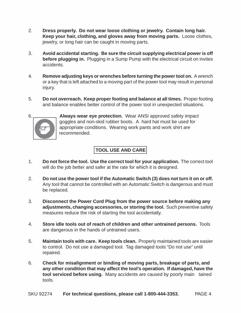
2. Dress properly. Do not wear loose clothing or jewelry. Contain long hair.Keep your hair, clothing, and gloves away from moving parts. Loose clothes,jewelry, or long hair can be caught in moving parts.
3. Avoid accidental starting. Be sure the circuit supplying electrical power is offbefore plugging in. Plugging in a Sump Pump with the electrical circuit on invitesaccidents.
4. Remove adjusting keys or wrenches before turning the power tool on. A wrenchor a key that is left attached to a moving part of the power tool may result in personalinjury.
5. Do not overreach. Keep proper footing and balance at all times. Proper footingand balance enables better control of the power tool in unexpected situations.
6. Always wear eye protection. Wear ANSI approved safety impact goggles and non-skid rubber boots. A hard hat must be used for appropriate conditions. Wearing work pants and work shirt are recommended.
TOOL USE AND CARE
1. Do not force the tool. Use the correct tool for your application. The correct toolwill do the job better and safer at the rate for which it is designed.
2. Do not use the power tool if the Automatic Switch (3) does not turn it on or off.Any tool that cannot be controlled with an Automatic Switch is dangerous and mustbe replaced.
3. Disconnect the Power Cord Plug from the power source before making anyadjustments, changing accessories, or storing the tool. Such preventive safetymeasures reduce the risk of starting the tool accidentally.
4. Store idle tools out of reach of children and other untrained persons. Toolsare dangerous in the hands of untrained users.
5. Maintain tools with care. Keep tools clean. Properly maintained tools are easierto control. Do not use a damaged tool. Tag damaged tools “Do not use” untilrepaired.
SKU 92274 For technical questions, please call 1-800-444-3353. PAGE 4
6. Check for misalignment or binding of moving parts, breakage of parts, andany other condition that may affect the tool’s operation. If damaged, have thetool serviced before using. Many accidents are caused by poorly main tainedtools.
7. Use only accessories that are recommended by the manufacturer for yourmodel. Accessories that may be suitable for one tool may become hazardouswhen used on another tool.
SERVICE
1. Tool service must be performed only by qualified repair personnel. Serviceor maintenance performed by unqualified personnel could result in a risk of injury.
2. When servicing a tool, use only identical replacement parts. Followinstructions in the “Inspection, Maintenance, And Cleaning” section of thismanual. Use of unauthorized parts or failure to follow maintenance instructionsmay create a risk of electric shock or injury.
GROUNDING
WARNING!
Improperly connecting the grounding wire can result in the risk of electricshock. Check with a qualified electrician if you are in doubt as to whether theoutlet is properly grounded. Do not modify the power cord plug provided with
the tool. Never remove the grounding prong from the plug. Do not use thetool if the power cord or plug is damaged. If damaged, have it repaired bya service facility before use. If the plug will not fit the outlet, have a proper
outlet installed by a qualified electrician.
GROUNDED TOOLS: TOOLS WITH THREE PRONG PLUGS
1. Tools marked with “Grounding Required” have a three wire cord and three pronggrounding plug. The plug must be connected to a properly grounded outlet. Ifthe tool should electrically malfunction or break down, grounding provides a lowresistance path to carry electricity aways from the user, reducing the risk ofelectric shock. (See Figure A, next page.)
SKU 92274 For technical questions, please call 1-800-444-3353 PAGE 5
2. The grounding prong in the plug is connected through the green wire inside thecord to the grounding system in the tool. The green wire in the cord must be theonly wire connected to the tool’s grounding system and must never be attachedto an electrically “live” terminal. (See Figure A.)

SKU 92274 For technical questions, please call 1-800-444-3353. PAGE 6
V ~
Ano xxxx/min.
No Load Revolutionsper Minute (RPM)
Amperes
Volts Alternating Current
UnderwritersLaboratories, Inc.
Canadian StandardsAssociation
Double Insulated
SYMBOLOGY
FIGURE B
3. Your tool must be plugged into an appropriate outlet, properly installed andgrounded in accordance with all codes and ordinances. The plug and outletshould look like that in the following illustration. (See Figure A.)
FIGURE A
3-PRONG PLUG
115 VOLT,GROUNDED,
ELECTRICAL OUTLET
SKU 92274 For technical questions, please call 1-800-444-3353. PAGE 7
1. Maintain labels and nameplates on the Sump Pump. These carry importantinformation. If unreadable or missing, contact Harbor Freight Tools for a replace-ment.
2. Use the right product for the right job. There are certain applications forwhich this product was designed. Do not use small equipment, tools, or attach-ments to do the work of larger industrial equipment, tools, or attachments. Donot use this product for a purpose for which it was not intended.
3. WARNING! Risk of electrical shock. Always disconnect the SumpPump from its power source before handling or making any adjustments. Alwayswear non-skid rubber boots when water is on the floor and you must unplug theSump Pump. Never allow the Motor to get wet. Make sure the electrical powersource is a separately fused, grounded, 3-wire type outlet of 15 AMP capacity.DO NOT REMOVE THE GROUND PRONG OR PLUG. DO NOT USE ANEXTENSION CORD.
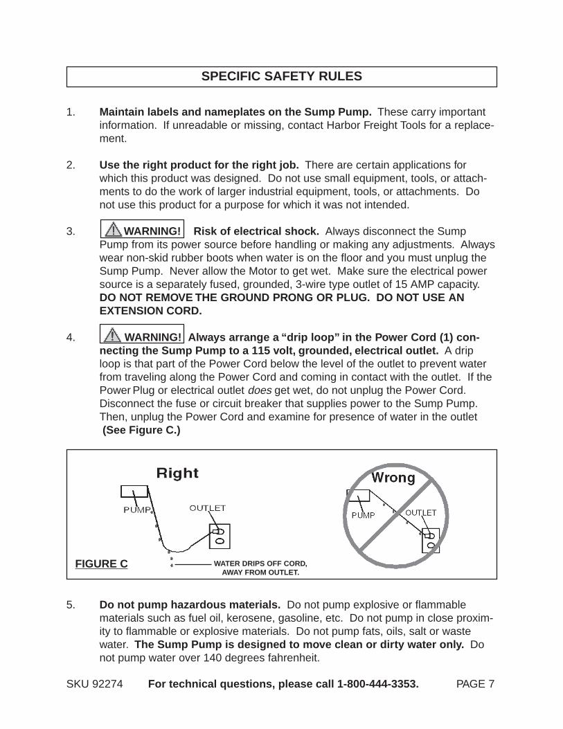
4. WARNING! Always arrange a “drip loop” in the Power Cord (1) con-necting the Sump Pump to a 115 volt, grounded, electrical outlet. A driploop is that part of the Power Cord below the level of the outlet to prevent waterfrom traveling along the Power Cord and coming in contact with the outlet. If thePower Plug or electrical outlet does get wet, do not unplug the Power Cord.Disconnect the fuse or circuit breaker that supplies power to the Sump Pump.Then, unplug the Power Cord and examine for presence of water in the outlet (See Figure C.)
SPECIFIC SAFETY RULES
FIGURE C
5. Do not pump hazardous materials. Do not pump explosive or flammablematerials such as fuel oil, kerosene, gasoline, etc. Do not pump in close proxim-ity to flammable or explosive materials. Do not pump fats, oils, salt or wastewater. The Sump Pump is designed to move clean or dirty water only. Donot pump water over 140 degrees fahrenheit.
WATER DRIPS OFF CORD,AWAY FROM OUTLET.

SKU 92274 For technical questions, please call 1-800-444-3353. PAGE 8
6. Water transfers in cycles. Do not attempt to manipulate the automatic Switch(3) to keep the Sump Pump running continuously. It is meant to shut offintermittently. Doing so will damage the Pump.
7. Make sure the discharge pipe (not included) is secured to a solid surface toensure the stability of the Sump Pump.
8. Make sure to position the Base Plate (24) of the Sump Pump on a flat, levelsurface.
9. If necessary, have a certified electrician install (within six feet of where theSump Pump will be located) a 115 volt, grounded, electrical outlet that isdedicated only to the Pump. Any outlet must be above the water line.
10. In cold weather, when the Sump Pump is not in use, protect the interior ofthe Pump from freezing by draining the liquid and pumping a permanenttype automobile anti-freeze containing a rust inhibitor through the system.A 50% mixture with water is recommended. Be sure to flush the system with aneutralizing liquid prior to re-use of the unit.
11. Prior to use, and periodically thereafter, check to make sure all connectionsare tight and secure.
12. Industrial applications must follow OSHA requirements.
13. Performance of this machine (if powered by line voltage) may vary depend-ing on variations in local line voltage.
14. Prior to use, and periodically thereafter, check to make sure the Float Rod(10) moves freely.
15. WARNING! People with pacemakers should consult their physician(s)before using this product. Operation of electrical equipment in close proximity toa heart pacemaker could cause interference or failure of the pacemaker.
16. WARNING! The warnings and cautions discussed in this manual cannotcover all possible conditions and situations that may occur. It must be under-stood by the operator that common sense and caution are factors which cannotbe built into this product, but must be supplied the the operator.
SAVE THESE INSTRUCTIONS
SKU 92274 For technical questions, please call 1-800-444-3353. PAGE 9
ASSEMBLY AND OPERATING INSTRUCTIONS
NOTE: For additional information regarding the parts listed in the following pages, referto the Assembly Diagram on page 14.
1. If necessary, have a certified electrician install (within six feet of where the SumpPump will be located) a 115 volt, grounded, electrical outlet that is dedicated onlyto the Pump. Any outlet must be above the water line.
1. WARNING! Always make sure the Sump Pump is unplugged from itselectrical outlet prior to assembling the unit, unclogging the unit, or making anyadjustments to the unit.
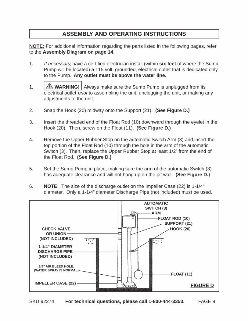
2. Snap the Hook (20) midway onto the Support (21). (See Figure D.)
3. Insert the threaded end of the Float Rod (10) downward through the eyelet in theHook (20). Then, screw on the Float (11). (See Figure D.)
4. Remove the Upper Rubber Stop on the automatic Switch Arm (3) and insert thetop portion of the Float Rod (10) through the hole in the arm of the automaticSwitch (3). Then, replace the Upper Rubber Stop at least 1/2” from the end ofthe Float Rod. (See Figure D.)
5. Set the Sump Pump in place, making sure the arm of the automatic Switch (3)has adequate clearance and will not hang up on the pit wall. (See Figure D.)
6. NOTE: The size of the discharge outlet on the Impeller Case (22) is 1-1/4”diameter. Only a 1-1/4” diameter Discharge Pipe (not included) must be used.
FIGURE D
AUTOMATICSWITCH (3)
ARMFLOAT ROD (10)
HOOK (20)SUPPORT (21)
FLOAT (11)
IMPELLER CASE (22)
1-1/4” DIAMETERDISCHARGE PIPE(NOT INCLUDED)
CHECK VALVEOR UNION
(NOT INCLUDED)
1/8” AIR BLEED HOLE.(WATER SPRAY IS NORMAL)
SKU 92274 For technical questions, please call 1-800-444-3353. PAGE 10
7. Connect the 1-1/4” diameter Discharge Pipe to the Impeller Case (22) of theSump Pump. Make sure to hand tighten only. Over tightening may cause theImpeller Case to crack. NOTE: Make sure the Discharge Pipe is secured to asolid surface, with appropriate hardware (not included), to ensure the stability ofthe Sump Pump. (See Figure D.)
8. Install a Union (not included) or other means of separating the Discharge Pipejust above the floor to facilitate removal of the Sump Pump if necessary.(See Figure D.)
9. NOTE: A Check Valve (not included) is recommended just above, or in place of,the Union to prevent the backflow of water after each pump cycle. If a CheckValve is used, a 1/8” diameter air bleed hole should be drilled through the Discharge Pipe just above the Impeller Case (22) to prevent pump “airlock”. A smallspray of water out of this hole is normal while pump is running. (See Figure D.)
10. Connect additional Discharge Pipe as needed to direct the discharge to thedesired location. The discharge should be kept as short as possible witha minimum number of turns. NOTE: The maximum lift of the Pump is 17 feet.
11. Plug the Power Cord into the nearest 115 volt, grounded, electrical outlet whilemaking sure to form a “drip loop” in the Power Cord. (See Figure C.)
12. The Sump Pump is now ready for operation.
13. NOTE: Periodically, check to make sure all connections are tight and secure.Also, make sure the Float Rod (10) moves freely.
TROUBLESHOOTING
1. WARNING! Always make sure the Sump Pump is unplugged from itselectrical outlet prior to performing any maintenance to the unit. This Section isdesigned to help identify reasons for operating problems. It is not a serviceguide. Dismantling the Sump Pump voids warranty. Servicing of the SumpPump (other than simple cleaning or unplugging) should be done only by a quali-fied service technician.
2. Pump Motor does not run.A. Line circuit breaker may be off. Have a certified electrician check the fuse or
breaker.
Do not attempt to reduce the discharge size below 1-1/4” as this will affect Pumpflow and performance. A Schedule 40 PVC 1-1/4” diameter Pipe is recom-mended. (See Figure D.)

SKU 92274 For technical questions, please call 1-800-444-3353. PAGE 11
C. Power Cord may not be making contact in electrical outlet. Check connec- tion.D. Float may be obstructed. Make sure the Float is free and not rubbing against the pit wall or other obstruction.
3. Pump Motor Runs, but does not discharge water.A. Check Valve (not included) may be installed backwards or is defective. Check to make sure it is installed properly and flapper in valve is free to move.B. Discharge Pipe may be frozen or blocked. Check to see if Discharge Pipe passes through cold areas or is blocked.C. Sump Pump may be airlocked. Check to see if air bleed hole is open.D. Vertical lift is beyond Sump Pump’s capability. Maximum lift capability is 17 feet.E. Inlet screen of Sump Pump is blocked, or Impeller is jammed. Remove Pump and clean inlet screen and Impeller.
4. Pump Motor runs and discharges water, but will not shut off.A. Float is stuck in the “ON” position. Check to make sure Float is free to move up and down without interference.B. Switch is not working. Have a qualified service technician replace Switch.
5. Pump Motor runs, but delivers small amount of water.A. Vertical lift is approaching Sump Pump’s maximum lift capability. Maximum lift capability is 17 feet. Reduce height of vertical lift.B. Inlet is partially blocked. Check to make sure inlet is clear of debris.C. Discharge Pipe is partially blocked. Check Pipe for blockage.D. Check Valve is not opening all the way. Check for defective or blocked Check Valve.
6. Circuit breaker trips or fuse blows when Sump Pump starts.A. Breaker or fuse size is too small. A minimum 15 AMP breaker or fuse should be used.B. Other major appliances are on the same circuit. Sump Pump should be on its own separate circuit.C. Sump Pump is connected to an extension cord, or wiring is inadequate. DO NOT USE EXTENSION CORDS. Have a certified electrician check for proper wiring.D. Switch or Motor not working. Have a qualified service technician check Switch and Motor for proper operation.
B. Water level in pit may be too low (Switch has not yet activated). Add more water to pit.
INSPECTION, MAINTENANCE, AND CLEANING
SKU 92274 For technical questions, please call 1-800-444-3353. PAGE 12
1. WARNING! Make sure the Sump Pump is unplugged from its electricaloutlet before performing any inspection, maintenance, or cleaning procedures.
2. Before each use, inspect the general condition of the Sump Pump. Check forclogs throughout the system, misalignment or binding of moving parts, damagedelectrical wiring, damaged or loose discharge pipes, and any other condition thatmay affect its safe operation. If abnormal noise or vibration occurs, have theproblem corrected before further use. Do not use damaged equipment.
3. Every six months, pour an ounce of 30 weight oil into the hole near the top ofthe Support (21). A label next to the hole indicates where to add the oil.
4. The Motor is permanently lubricated and requires no additional lubrication.
5. If the Sump Pump is not in use due to dry conditions, etc., pour enoughwater into the pit to activate the Pump once every 3 months.
6. Periodically, check to make sure the pit is free from accumulated debris, rocks,and other objects that may damage the Sump Pump.
7. When cleaning, NEVER introduce water or any other liquid into the Motor Hous-ing.
8. In cold weather, when the Sump Pump is not in use, protect the interior of thePump from freezing by draining the liquid and pumping a permanent type auto-mobile anti-freeze containing a rust inhibitor through the system. A 50% mixturewith water is recommended. Be sure to flush the system with a neutralizing liquidprior to re-use of the unit.
9. CAUTION! All maintenance, service, or repairs not listed in thismanual are only to be attempted by a qualified service technician.
PLEASE READ THE FOLLOWING CAREFULLY
THE MANUFACTURER AND/OR DISTRIBUTOR HAS PROVIDED THE PARTS LIST AND ASSEMBLY DIAGRAM IN THIS MANUALAS A REFERENCE TOOL ONLY. NEITHER THE MANUFACTURER OR DISTRIBUTOR MAKES ANY REPRESENTATION ORWARRANTY OF ANY KIND TO THE BUYER THAT HE OR SHE IS QUALIFIED TO MAKE ANY REPAIRS TO THE PRODUCT, ORTHAT HE OR SHE IS QUALIFIED TO REPLACE ANY PARTS OF THE PRODUCT. IN FACT, THE MANUFACTURER AND/ORDISTRIBUTOR EXPRESSLY STATES THAT ALL REPAIRS AND PARTS REPLACEMENTS SHOULD BE UNDERTAKEN BY CERTIFIEDAND LICENSED TECHNICIANS, AND NOT BY THE BUYER. THE BUYER ASSUMES ALL RISK AND LIABILITY ARISING OUT OFHIS OR HER REPAIRS TO THE ORIGINAL PRODUCT OR REPLACEMENT PARTS THERETO, OR ARISING OUT OF HIS OR HERINSTALLATION OF REPLACEMENT PARTS THERETO.

PARTS LIST
SKU 92274 For technical questions, please call 1-800-444-3353. PAGE 13
NOTE:Some parts are listed and shown for illustration purposes only,
and are not available individually as replacement parts.
Part # Description Qty. Part # Description Qty.1 Power Cord 1 14 Rotor 12 Screw 2 15 Fan 13 Switch 1 16 Front Cover 14 Motor Rear Cover 1 17 Screw 55 Star Washer 1 18 Screw 46 Screw 2 19 Shaft 17 Capacitor 1 20 Hook 18 Motor Enclosure 1 21 Support 19 Cable Clamp 1 22 Impeller Case 110 Float Rod 1 23 Impeller 111 Float 1 24 Base Plate 112 Stator 1 25 Screw 513 Bearing 2
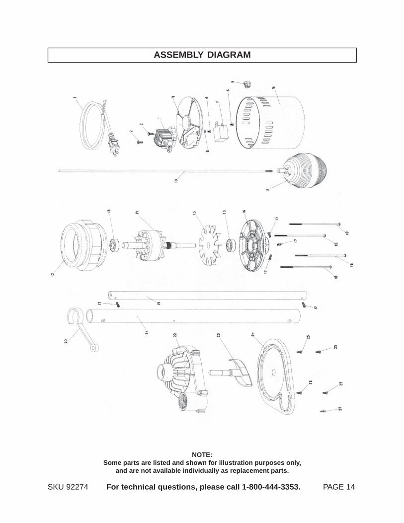
ASSEMBLY DIAGRAM
SKU 92274 For technical questions, please call 1-800-444-3353. PAGE 14
NOTE:Some parts are listed and shown for illustration purposes only,
and are not available individually as replacement parts.