913200 Engine Trend Monitor Pilot’s Operation Manual · CAUTION:IF THE PILOT STARTS THE ENGINE...
62
Page T-1 25 Sep 2007 Publication Number OM-913200-001, Rev. 002 Revised, 22 Aug 2008 913200 Engine Trend Monitor Pilot’s Operation Manual
Transcript of 913200 Engine Trend Monitor Pilot’s Operation Manual · CAUTION:IF THE PILOT STARTS THE ENGINE...

913200
Engine Trend Monitor
Pilot’s Operation Manual
Page T-125 Sep 2007
Publication Number OM-913200-001, Rev. 002 Revised, 22 Aug 2008

Pilot’s Operation Manual913200 Engine Trend Monitor
COPYRIGHT - NOTICEThis document and the information disclosed herein are proprietary data of Shadin Avionics. Neither this document nor the information contained herein shall be used, reproduced, or disclosed to others without the written authorization of Shadin Avionics, except to the extent necessary for installation or maintenance of recipient’s equipment.
Note: FREEDOM OF INFORMATION ACT (5 USC 552) AND DISCLOSURE OF CONFIDENTIAL INFORMATION GEN-ERALLY (18 USC 1905)
This document is being furnished in confidence by Shadin Avionics. The information disclosed herein falls within exemption (b) (4) of 5 USC 552 and the provisions of 18 USC 1905. Copyright 2008 Shadin LP (d/b/a Shadin Avionics). All Rights Reserved.
Page T-2Pub. No OM-913200-001, Rev. 002 22 Aug 2008

Pilot’s Operation Manual913200 Engine Trend Monitor
RECORD OF REVISIONS
Rev.No.
Rev.Date Change Description
Initial Issue
25 Sep 2007
001 29 Jul 2008 Update to include additional ETM models
002 22 Aug 2008 Editorial changes thoughout
Page RR-1Pub. No OM-913200-001, Rev. 002 22 Aug 2008

Pilot’s Operation Manual913200 Engine Trend Monitor
Blank Page
Page RR-2Pub. No OM-913200-001, Rev. 002 22 Aug 2008

Pilot’s Operation Manual913200 Engine Trend Monitor
EFFECTIVE PAGES
Section/Page Date Section/Page Date
Title Page Section 7 - Automatic Functions
T-1 thru T-2 22 Aug 2008 7-1 thru 7-4 22 Aug 2008
Record of Revisions Section 8 - Auxiliary Functions
RR-1 thru RR-2 22 Aug 2008 8-1 thru 8-2 22 Aug 2008
Effective Pages Section 9 - Parameter Record
LEP-1 thru LEP-2
22 Aug 2008 9-1 thru 9-2 22 Aug 2008
Table of Contents
TC-1 thru TC-2 22 Aug 2008
Introduction
INTRO-1 thru INTRO-4
22 Aug 2008
Section 1 - System Overview
1-1 thru 1-2 22 Aug 2008
Section 2 - Operational Mode
2-1 thru 2-4 22 Aug 2008
Section 3 - ETM File
3-1 thru 3-16 22 Aug 2008
Section 4 - NAV File
4-1 thru 4-6 22 Aug 2008
Section 5 - Fuel File
5-1 thru 5-8 22 Aug 2008
Section 6 - Airdata File
6-1 thru 6-4 22 Aug 2008
Page LEP-1Pub. No OM-913200-001, Rev. 002 22 Aug 2008

Pilot’s Operation Manual913200 Engine Trend Monitor
Blank Page
Page LEP-2Pub. No OM-913200-001, Rev. 002 22 Aug 2008

Pilot’s Operation Manual913200 Engine Trend Monitor
TABLE OF CONTENTSSection/Paragraph PageIntroduction . . . . . . . . . . . . . . . . . . . . . . . . . . . . . . . . . . . . . . . . . . . . . . . INTRO-1Section 1 - System Overview. . . . . . . . . . . . . . . . . . . . . . . . . . . . . . . . . . . . . . 1 - 1
Parts Breakdown . . . . . . . . . . . . . . . . . . . . . . . . . . . . . . . . . . . . . . . . . . 1 - 1System Capabilities and Features . . . . . . . . . . . . . . . . . . . . . . . . . . . . . 1 - 1
Section 2 - Operational Mode . . . . . . . . . . . . . . . . . . . . . . . . . . . . . . . . . . . . . 2 - 1Section 3 - ETM File . . . . . . . . . . . . . . . . . . . . . . . . . . . . . . . . . . . . . . . . . . . . 3 - 1
Gas Generator Speed (NG or N1) and Turbine Temperature (ITT or TOT) . . . . . . . . . . . . . . . . . . . . . . . . . . . . . . . . . . . 3 - 2Torque (TQ) and Turbine Temperature (ITT or TOT) . . . . . . . . . . . . . . . 3 - 2Propeller Speed (NP or N2) and Gas Generator Speed (NG or N1) . . . 3 - 2Shaft Horsepower (HP) . . . . . . . . . . . . . . . . . . . . . . . . . . . . . . . . . . . . . . 3 - 3Specific Fuel Consumption . . . . . . . . . . . . . . . . . . . . . . . . . . . . . . . . . . . 3 - 3Ground Power Check . . . . . . . . . . . . . . . . . . . . . . . . . . . . . . . . . . . . . . . 3 - 4Key Status. . . . . . . . . . . . . . . . . . . . . . . . . . . . . . . . . . . . . . . . . . . . . . . . 3 - 8Log of Totals . . . . . . . . . . . . . . . . . . . . . . . . . . . . . . . . . . . . . . . . . . . . . . 3 - 9Exceedance File Review. . . . . . . . . . . . . . . . . . . . . . . . . . . . . . . . . . . . 3 - 11Exceedance Specifications . . . . . . . . . . . . . . . . . . . . . . . . . . . . . . . . . . 3 - 13Lowest Bus Voltage / Highest ITT Values at Engine Start . . . . . . . . . . 3 - 15Next Inspection Countdown Timer . . . . . . . . . . . . . . . . . . . . . . . . . . . . 3 - 16
Section 4 - NAV File. . . . . . . . . . . . . . . . . . . . . . . . . . . . . . . . . . . . . . . . . . . . . 4 - 1Current Position of the Aircraft . . . . . . . . . . . . . . . . . . . . . . . . . . . . . . . . 4 - 2Estimated Time En Route to Next Waypoint . . . . . . . . . . . . . . . . . . . . . . 4 - 2Estimated Time of Arrival at Next Waypoint . . . . . . . . . . . . . . . . . . . . . . 4 - 3Estimated Time En Route to Final Destination . . . . . . . . . . . . . . . . . . . . 4 - 3Estimated Time of Arrival at Final Destination . . . . . . . . . . . . . . . . . . . . 4 - 3Magnetic Track and Ground Speed . . . . . . . . . . . . . . . . . . . . . . . . . . . . 4 - 3Wind Speed and Direction / Drift Angle. . . . . . . . . . . . . . . . . . . . . . . . . . 4 - 4Aircraft Heading / Drift Angle. . . . . . . . . . . . . . . . . . . . . . . . . . . . . . . . . . 4 - 4Aircraft Heading / Rate Of Turn (ROT) . . . . . . . . . . . . . . . . . . . . . . . . . . 4 - 5
Section 5 - Fuel File . . . . . . . . . . . . . . . . . . . . . . . . . . . . . . . . . . . . . . . . . . . . . 5 - 1Full Fuel . . . . . . . . . . . . . . . . . . . . . . . . . . . . . . . . . . . . . . . . . . . . . . . . . 5 - 2Fuel to Destination . . . . . . . . . . . . . . . . . . . . . . . . . . . . . . . . . . . . . . . . . 5 - 3Fuel at Destination . . . . . . . . . . . . . . . . . . . . . . . . . . . . . . . . . . . . . . . . . 5 - 3Specific Range . . . . . . . . . . . . . . . . . . . . . . . . . . . . . . . . . . . . . . . . . . . . 5 - 4Fuel Flow. . . . . . . . . . . . . . . . . . . . . . . . . . . . . . . . . . . . . . . . . . . . . . . . . 5 - 4Fuel Used / Remaining (total) . . . . . . . . . . . . . . . . . . . . . . . . . . . . . . . . . 5 - 5Fuel Used (per engine) . . . . . . . . . . . . . . . . . . . . . . . . . . . . . . . . . . . . . . 5 - 5Time Remaining . . . . . . . . . . . . . . . . . . . . . . . . . . . . . . . . . . . . . . . . . . . 5 - 6Added Fuel . . . . . . . . . . . . . . . . . . . . . . . . . . . . . . . . . . . . . . . . . . . . . . . 5 - 6Fuel Set Point . . . . . . . . . . . . . . . . . . . . . . . . . . . . . . . . . . . . . . . . . . . . . 5 - 7
Section 6 - Airdata File. . . . . . . . . . . . . . . . . . . . . . . . . . . . . . . . . . . . . . . . . . . 6 - 1Date and Local Time . . . . . . . . . . . . . . . . . . . . . . . . . . . . . . . . . . . . . . . . 6 - 2Greenwich Mean Time . . . . . . . . . . . . . . . . . . . . . . . . . . . . . . . . . . . . . . 6 - 2Flight Timer . . . . . . . . . . . . . . . . . . . . . . . . . . . . . . . . . . . . . . . . . . . . . . . 6 - 2
Page TC-1Pub. No OM-913200-001, Rev. 002 22 Aug 2008

Pilot’s Operation Manual913200 Engine Trend Monitor
Outside Air Temperature and Density Altitude or Outside Air Temperature and Static Air Temperature . . . . . . . . . . . . . . . . . . . . . . . . . . . . . . . . . . . 6 - 3Pressure Altitude and Density Altitude . . . . . . . . . . . . . . . . . . . . . . . . . . 6 - 3IAS, TAS, and MACH . . . . . . . . . . . . . . . . . . . . . . . . . . . . . . . . . . . . . . . 6 - 4Gross Weight. . . . . . . . . . . . . . . . . . . . . . . . . . . . . . . . . . . . . . . . . . . . . . 6 - 4
Section 7 - Automatic Functions. . . . . . . . . . . . . . . . . . . . . . . . . . . . . . . . . . . . 7 - 1Power Check . . . . . . . . . . . . . . . . . . . . . . . . . . . . . . . . . . . . . . . . . . . . . . 7 - 1Exceedance Alarms. . . . . . . . . . . . . . . . . . . . . . . . . . . . . . . . . . . . . . . . . 7 - 1POPUP MESSAGES. . . . . . . . . . . . . . . . . . . . . . . . . . . . . . . . . . . . . . . . 7 - 2
Section 8 - Auxiliary Functions. . . . . . . . . . . . . . . . . . . . . . . . . . . . . . . . . . . . . 8 - 1Stopwatch . . . . . . . . . . . . . . . . . . . . . . . . . . . . . . . . . . . . . . . . . . . . . . . . 8 - 1Self Test . . . . . . . . . . . . . . . . . . . . . . . . . . . . . . . . . . . . . . . . . . . . . . . . . 8 - 1
Section 9 - Parameter Record . . . . . . . . . . . . . . . . . . . . . . . . . . . . . . . . . . . . . 9 - 1
Page TC-2Pub. No OM-913200-001, Rev. 002 22 Aug 2008
Pilot’s Operation Manual913200 Engine Trend Monitor
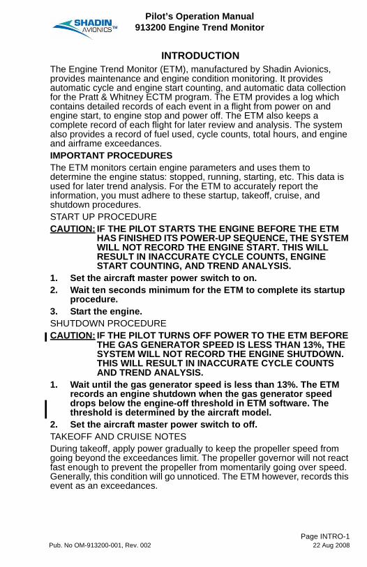
INTRODUCTIONThe Engine Trend Monitor (ETM), manufactured by Shadin Avionics, provides maintenance and engine condition monitoring. It provides automatic cycle and engine start counting, and automatic data collection for the Pratt & Whitney ECTM program. The ETM provides a log which contains detailed records of each event in a flight from power on and engine start, to engine stop and power off. The ETM also keeps a complete record of each flight for later review and analysis. The system also provides a record of fuel used, cycle counts, total hours, and engine and airframe exceedances.IMPORTANT PROCEDURESThe ETM monitors certain engine parameters and uses them to determine the engine status: stopped, running, starting, etc. This data is used for later trend analysis. For the ETM to accurately report the information, you must adhere to these startup, takeoff, cruise, and shutdown procedures.START UP PROCEDURECAUTION: IF THE PILOT STARTS THE ENGINE BEFORE THE ETM
HAS FINISHED ITS POWER-UP SEQUENCE, THE SYSTEM WILL NOT RECORD THE ENGINE START. THIS WILL RESULT IN INACCURATE CYCLE COUNTS, ENGINE START COUNTING, AND TREND ANALYSIS.
1. Set the aircraft master power switch to on.2. Wait ten seconds minimum for the ETM to complete its startup
procedure.3. Start the engine.SHUTDOWN PROCEDURECAUTION: IF THE PILOT TURNS OFF POWER TO THE ETM BEFORE
THE GAS GENERATOR SPEED IS LESS THAN 13%, THE SYSTEM WILL NOT RECORD THE ENGINE SHUTDOWN. THIS WILL RESULT IN INACCURATE CYCLE COUNTS AND TREND ANALYSIS.
1. Wait until the gas generator speed is less than 13%. The ETM records an engine shutdown when the gas generator speed drops below the engine-off threshold in ETM software. The threshold is determined by the aircraft model.
2. Set the aircraft master power switch to off.TAKEOFF AND CRUISE NOTESDuring takeoff, apply power gradually to keep the propeller speed from going beyond the exceedances limit. The propeller governor will not react fast enough to prevent the propeller from momentarily going over speed. Generally, this condition will go unnoticed. The ETM however, records this event as an exceedances.
Page INTRO-1Pub. No OM-913200-001, Rev. 002 22 Aug 2008

Pilot’s Operation Manual913200 Engine Trend Monitor
ETM TERMINOLOGYThis manual uses terms to designate features or functions of the ETM. These paragraphs describe the terms.• "File"- A file is the broadest category of organization in the ETM.
Each location on the rotary switch (located on the lower left side of the ETM) corresponds to a file.
• "Page"- This is the next category of organization after a file. Each file generally contains 5 to 10 pages. The PAGE UP/DOWN switch, located in the lower center of the ETM, scrolls through the various pages. See below for an example of file and page organization.
• "Indicator Face"- The indicator face is the entire faceplate of the ETM. It includes the controls and display.
• "Display"- The display is the small screen in the center of the ETM. The display has two, 12-character lines to show data.
• "Exceedance"- The ETM has specific manufacturer's data for the aircraft in which it is installed. This body of data provides the ETM with the aircraft performance parameters. If the aircraft exceeds or violates the parameters, the ETM records the exceedance on the output device. If enabled by the installer, the exceedance is also displayed by the ETM.
• "Mode"- The ETM has three modes: Data Entry, Diagnostic, and Operational. Each of these modes has different file and control assignments. This manual describes the Operational Mode. Data Entry and Diagnostic Modes are used by installation and maintenance personnel.
• “Operator” - The terms pilot, user, and operator are interchangeable.
AIRDATAFUELNAVETM
FILE
Various pagescontained within
the file
913200-0001A
Page INTRO-2Pub. No OM-913200-001, Rev. 002 22 Aug 2008

Pilot’s Operation Manual913200 Engine Trend Monitor
MANUAL CONTENTThis manual provides the following:• A system overview (Section 1)• A description of the ETM operational mode (Section 2)• A description for each File (Sections 3 through 6)• A description of Automatic Functions (Section 7)• A description of Auxiliary Functions (Section 8).NOTE: Example displays shown in this manual are from twin engine
aircraft and show two parameters. Displays for single engine aircraft are the same but show no left or right engine indication and show one parameter.
Twin Engine
Single Engine
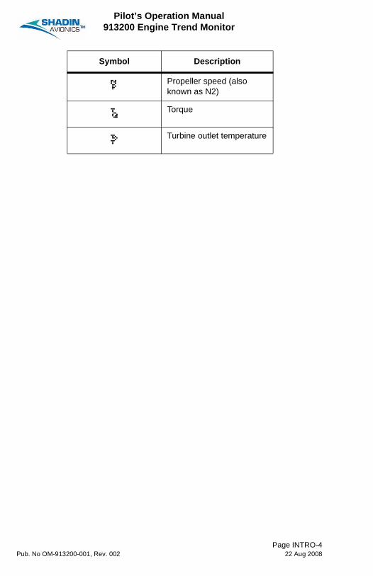
The following shows parameter symbols that show in the displays.
Symbol Description
¦ Inter-turbine temperature
Á Gas generator speed (also known as NG)
¡ Propeller speed (also known as NP)
¢ Gas generator speed (also known as N1)
¢%L 92ØR 92Ù
¦¨L 835R 834
¢% 92Ø
¦¨ 835
Page INTRO-3Pub. No OM-913200-001, Rev. 002 22 Aug 2008
Pilot’s Operation Manual913200 Engine Trend Monitor
£ Propeller speed (also known as N2)
¥ Torque
§ Turbine outlet temperature
Symbol Description
Page INTRO-4Pub. No OM-913200-001, Rev. 002 22 Aug 2008

Pilot’s Operation Manual913200 Engine Trend Monitor
SECTION 1 - SYSTEM OVERVIEWThe Engine Trend Monitor (ETM) provides the aircraft owner, operator, and maintenance personnel with a complete, accurate, and detailed record of the aircraft's operation. A complete range of data is recorded; including engine and airframe data which can be used to optimize the aircraft's maintenance.1. Parts BreakdownThe ETM consists of several physical components. The number of parts in the overall system varies with the type of ETM. There are two types of ETM systems: integral and remote. Both types are identical in function and operation. The two systems differ in the physical arrangement of components.The integral ETM system, has three major components:• Panel mounted indicator and computer: this contains the main
components and processor for the system, controls, and display• Engine and environment sensors: these are the various probes and
sensors from which the ETM collects data.=• External data recorder: this part of the system is used for data
storage.The remote ETM system has a separate display and processor unit. The processor portion of the system is typically mounted in the aircraft's avionics bay. The display and controls are mounted in the cockpit panel.The remote ETM system consists of four components:• Panel mounted indicator: contains the controls and display • Remote mounted computer: contains the main components and
processor for the system.• Engine and environment sensors: these are the various probes and
sensors from which the ETM collects data.• External data recorder: this part of the system is used for data
storage.2. System Capabilities and FeaturesThe Engine Trend Monitor serves a multitude of functions for both the pilot and operator of the aircraft. The ETM monitors, displays, and records engine and airframe parameters. If desired, the system can also give an alert to the pilot when those parameters exceed established limits. The system provides the pilot with:• A centralized location for engine monitoring• Navigation data received from a GPS receiver• A complete fuel management system• Continuously updated air data. The air data is displayed and is
transmitted in serial formats.The ETM provides the maintenance personnel with:• A complete log of engine starts and total time• A complete log of airframe total cycles and total time
Page 1-1Pub. No OM-913200-001, Rev. 002 22 Aug 2008

Pilot’s Operation Manual913200 Engine Trend Monitor
• A complete and detailed record of every engine and airframe exceedance.
The ETM collects and records data for use with the Pratt & Whitney ECTM program in the form of power assurance checks.The Engine Trend Monitor System provides the following functions:• Monitor and display primary engine data: this includes engine
temperature, torque, propeller and turbine speeds.• Monitor and display primary air data: this includes pressure altitude,
indicated air speed, and outside air temperature.• Calculate and display secondary engine data: this includes shaft
horsepower and specific fuel consumption.• Calculate and display secondary air data: this includes density
altitude, true airspeed, wind speed and direction, mach, and drift.• Interface with a long range navigational receiver: the system displays
the aircraft position in latitude and longitude, ETE and ETA to next waypoint, magnetic track, ground speed, aircraft heading, drift angle, rate of turn, waypoint ID, and distance to destination data.
• Detect and record exceedances: both engine and airframe exceedances are recorded on the data output device and in the ETM.
• Priority display exceedances: if desired, the ETM can display exceedances to the pilot as they occur. If this function is enabled, the exceedance warning will override any other display, regardless of its function.
• Automatically keeps a log: engine total time, and number of starts as well as airframe total time and total cycles are automatically updated.
• Data Sampling: engine power check data, which is required as an input for subsequent analysis by the Pratt & Whitney ECTM program is automatically recorded by the ETM.
• Provides the pilot with a complete fuel management system: includes fuel flow, full fuel, added fuel, fuel remaining, fuel used, fuel at destination, and fuel to destination.
• Records events: engine starts, takeoffs, landings, engine shutdowns, engine power checks and user requested data are recorded in the form of printouts and key reports.
• Provides a multifunction clock and calendar: the clock displays both GMT and local time to the second. The calendar is used when entering the date into a report on the key. The stopwatch is an auxiliary feature and is not tied to a specific function.
Page 1-2Pub. No OM-913200-001, Rev. 002 22 Aug 2008
Pilot’s Operation Manual913200 Engine Trend Monitor
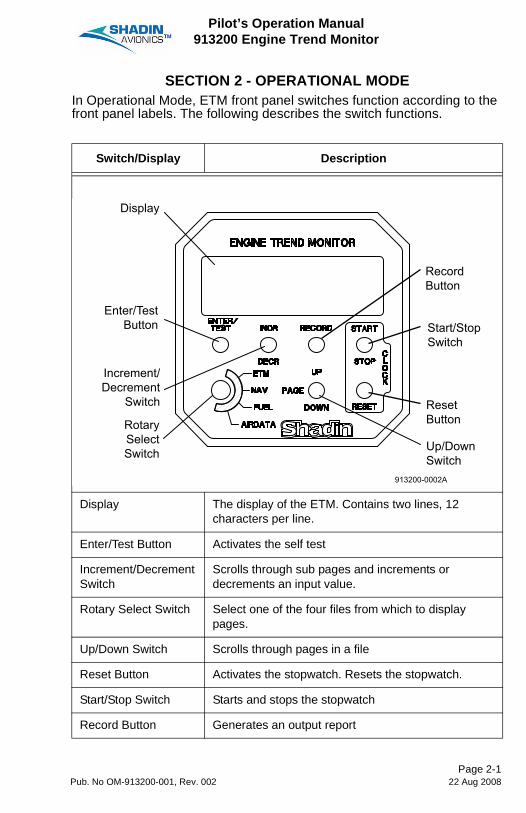
SECTION 2 - OPERATIONAL MODEIn Operational Mode, ETM front panel switches function according to the front panel labels. The following describes the switch functions.
Switch/Display Description
Display The display of the ETM. Contains two lines, 12 characters per line.
Enter/Test Button Activates the self test
Increment/Decrement Switch
Scrolls through sub pages and increments or decrements an input value.
Rotary Select Switch Select one of the four files from which to display pages.
Up/Down Switch Scrolls through pages in a file
Reset Button Activates the stopwatch. Resets the stopwatch.
Start/Stop Switch Starts and stops the stopwatch
Record Button Generates an output report
Display
Enter/TestButton
Increment/Decrement
Switch
RotarySelectSwitch Up/Down
Switch
ResetButton
Start/StopSwitch
RecordButton
913200-0002A
Page 2-1Pub. No OM-913200-001, Rev. 002 22 Aug 2008
Pilot’s Operation Manual913200 Engine Trend Monitor
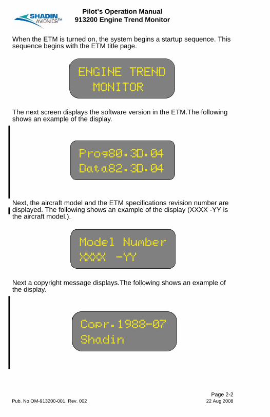
When the ETM is turned on, the system begins a startup sequence. This sequence begins with the ETM title page.
The next screen displays the software version in the ETM.The following shows an example of the display.
Next, the aircraft model and the ETM specifications revision number are displayed. The following shows an example of the display (XXXX -YY is the aircraft model.).
Next a copyright message displays.The following shows an example of the display.
ENGINE TREND
MONITOR
Prog80.3D.04
Data82.3D.04
Model Number
XXXX -YY
Copr.1988-07
Shadin
Page 2-2Pub. No OM-913200-001, Rev. 002 22 Aug 2008

Pilot’s Operation Manual913200 Engine Trend Monitor
After the startup sequence is finished, the unit enters the Operational Mode.In the operational mode, the ETM display pages are separated into four main files, with each file corresponding to one position of the rotary switch. The files are ETM, NAV, FUEL, and AIRDATA. Within each file the PAGE UP and PAGE DOWN switches are used to cycle through the various pages which can be displayed in each file. A description of the data to be viewed on each page and the procedures for any actions which can be performed on each page is given in the sections that follow.
Page 2-3Pub. No OM-913200-001, Rev. 002 22 Aug 2008

Pilot’s Operation Manual913200 Engine Trend Monitor
Blank Page
Page 2-4Pub. No OM-913200-001, Rev. 002 22 Aug 2008
Pilot’s Operation Manual913200 Engine Trend Monitor
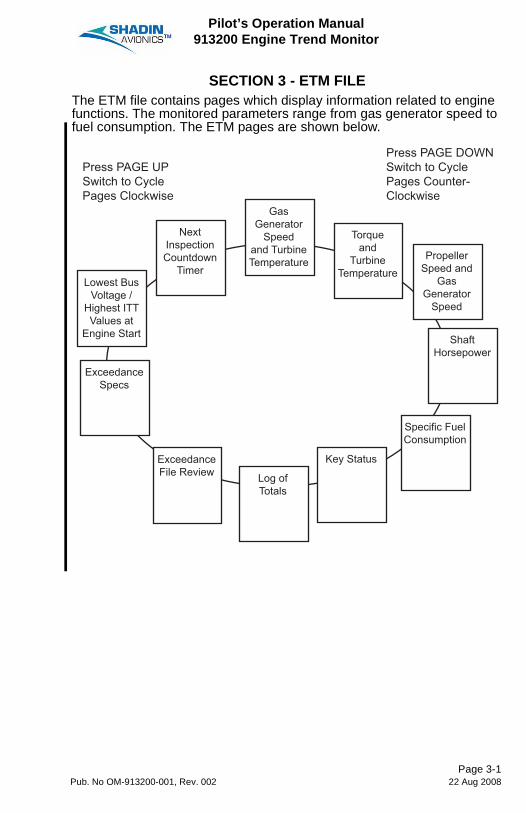
SECTION 3 - ETM FILEThe ETM file contains pages which display information related to engine functions. The monitored parameters range from gas generator speed to fuel consumption. The ETM pages are shown below.
Press PAGE UPSwitch to CyclePages Clockwise
Press PAGE DOWNSwitch to CyclePages Counter-Clockwise
Lowest BusVoltage /
Highest ITTValues at
Engine Start
ExceedanceFile Review Log of
Totals
Key Status
Specific FuelConsumption
ExceedanceSpecs
ShaftHorsepower
PropellerSpeed and
GasGenerator
Speed
Torqueand
TurbineTemperature
GasGenerator
Speedand TurbineTemperature
NextInspectionCountdown
Timer
Page 3-1Pub. No OM-913200-001, Rev. 002 22 Aug 2008

Pilot’s Operation Manual913200 Engine Trend Monitor
1. Gas Generator Speed (NG or N1) and Turbine Temperature (ITT or TOT)
The tachometer is displayed in the ETM as NG or N1, displayed as a percent (%). Also displayed on this page is the inter-turbine temperature (ITT) or turbine outlet temperature (TOT), displayed in degrees Celsius.
2. Torque (TQ) and Turbine Temperature (ITT or TOT)The torque page displays the torque (in foot-pounds) for the engine(s). If the engine is off, the display shows a series of dashes.
3. Propeller Speed (NP or N2) and Gas Generator Speed (NG or N1)The propeller speed is displayed on the lower line of this page as NP, and the value is given in RPM.
¢%L 92ØR 92Ù
¦¨L 835R 834
¥ L1350R1350
¦¨L 835R 834
¢%L 92ØR 92Ù
£ L1250R1250
Page 3-2Pub. No OM-913200-001, Rev. 002 22 Aug 2008

Pilot’s Operation Manual913200 Engine Trend Monitor
4. Shaft Horsepower (HP)The shaft horsepower is calculated for the engine(s) from the NP and the torque. This display is enabled in ETM software based on aircraft model.This is a real-time calculation of the engine output in horsepower.
5. Specific Fuel ConsumptionSpecific fuel consumption is a calculated value that measures the engine efficiency. The display indicates the number of pounds of fuel required by the engine to produce one horsepower. This page shows only if the shaft horsepower page is enabled in ETM software.In general the smaller the number, the more efficient the engine. For example, an engine with a specific fuel consumption of 0.500, is operating more efficiently than an engine with a specific fuel consumption of 0.600. What this comparison means is that, to produce the same amount of horsepower, the first engine is burning less fuel than the second.
SHAFT HP:
L602Ú R603Ò
SFC:
L.454 R.454
Page 3-3Pub. No OM-913200-001, Rev. 002 22 Aug 2008

Pilot’s Operation Manual913200 Engine Trend Monitor
6. Ground Power CheckNOTE: The ground power check function is not available in all
ETM. Availability is shown by a Ground Check page in the ETM file.
A. General DescriptionAll forms of engine deterioration will be accompanied by an increase in inter-turbine temperature and fuel flow at a given power setting. Compressor deterioration in most cases is due to dirt and sand ingestion and will increase the gas generator speed to obtain a given power setting. Power turbine deterioration will cause a decrease in the gas generator speed required for a given power setting. All of these symptoms are easily identified by ground power checks.Ground power checks are performed to evaluate the engine condition and the effects of maintenance, or to analyze faults due to engine deterioration. These performance checks are a normal maintenance procedure that must be carried out frequently and any changes in engine performance should be noted. (Please refer to your approved aircraft maintenance procedures to perform the ground power check.)There are three parts to the ground power check. First, the operator calculates input and output values for the engine. Second, the actual power check is performed, and data is collected. Third, the calculation of the "delta" values is performed.Part 1Before the test is performed, the operator must determine what the input and output values will be. The inputs are the values the operator will set, and the outputs are the values the operator will record at the end of the test to evaluate the condition of the engine. There are two input values and three output values. The inputs are: the torque (TQ) and propeller speed (NP). The outputs are: the gas generator speed (NG), inter-turbine temperature (ITT), and fuel flow.The torque and propeller speed are the values the operator will set. The operator must calculate a target torque and target propeller speed. The target torque is dictated by the ambient pressure conditions, while the target propeller speed is a predetermined value and is always the same RPM.For the output values, two different methods of measurement are used. For the gas generator speed and inter-turbine temperature, a maximum allowable value is determined. For the fuel flow, a target value is calculated based on the ambient pressure conditions.
Page 3-4Pub. No OM-913200-001, Rev. 002 22 Aug 2008
Pilot’s Operation Manual913200 Engine Trend Monitor
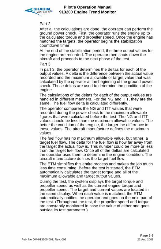
Part 2After all the calculations are done, the operator can perform the ground power check. First, the operator runs the engine up to the calculated torque and propeller speed. Once the engine has matched the targets, the operator begins the stabilization countdown timer.At the end of the stabilization period, the three output values for the engine are recorded. The operator then shuts down the aircraft and proceeds to the next phase of the test.Part 3In part 3, the operator determines the deltas for each of the output values. A delta is the difference between the actual value recorded and the maximum allowable or target value that was calculated by the operator at the beginning of the ground power check. These deltas are used to determine the condition of the engine.The calculations of the deltas for each of the output values are handled in different manners. For the NG and ITT, they are the same. The fuel flow delta is calculated differently.The operator compares the NG and ITT values that were recorded during the power check to the maximum allowable figures that were calculated before the test. The NG and ITT values should be less than the maximum allowable values. The better the condition of the engine, the larger the difference in these values. The aircraft manufacture defines the maximum values.The fuel flow has no maximum allowable value, but rather, a target fuel flow. The delta for the fuel flow is how far away from the target the actual flow is. This number could be more or less than the target fuel flow. Once all of the deltas are calculated the operator uses them to determine the engine condition. The aircraft manufacture defines the target fuel flow.The ETM simplifies this entire process and makes the job much less time consuming. Before the test is started, the ETM automatically calculates the target torque and all of the maximum allowable and target output values.During the test, the system displays the target torque and propeller speed as well as the current engine torque and propeller speed. The target and current values are located in the same display. When each value is matched, the ETM automatically notifies the operator and goes on the next part of the test. (Throughout the test, the propeller speed and torque are constantly monitored in case the value of either one goes outside its test parameter.)
Page 3-5Pub. No OM-913200-001, Rev. 002 22 Aug 2008
Pilot’s Operation Manual913200 Engine Trend Monitor
The ETM displays the stabilization timer and automatically snapshots the output values at the end of the waiting period. The system then calculates the deltas for each value, displays them in the cockpit, and writes them to the Datakey. The information can later be transferred to a ground based PC for evaluation, tracking, and comparison.This procedure allows the maintenance personnel to perform ground power checks more often. As more checks are performed, more data is collected. This increase in data helps in the analysis of problems with the engine and helps keep it in the best condition possible. The maintenance personnel can also identify faults more easily.The criteria for evaluating the engine data is up to the maintenance personnel. The ETM is simply providing an automated way to obtain the target torque and the maximum allowable limits from the charts; and an audit trail for data by printing all of the involved parameters. The system does not perform any type of engine analysis.
B. Ground Power Check ProcedureCAUTION: When performing a ground power check, always follow the
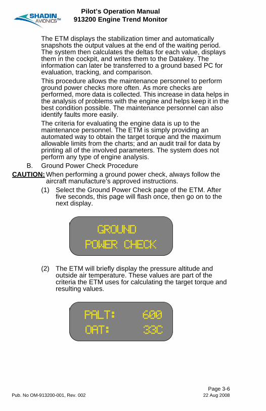
aircraft manufacture’s approved instructions.(1) Select the Ground Power Check page of the ETM. After
five seconds, this page will flash once, then go on to the next display.
(2) The ETM will briefly display the pressure altitude and outside air temperature. These values are part of the criteria the ETM uses for calculating the target torque and resulting values.
GROUND
POWER CHECK
PALT: 600
OAT: 33C
Page 3-6Pub. No OM-913200-001, Rev. 002 22 Aug 2008

Pilot’s Operation Manual913200 Engine Trend Monitor
(3) The ETM will now prompt you to bring your propeller speed within test parameters. The display below shows the target propeller speed and the current propeller speed. Bring the propeller speed to the target RPM. When they have been matched, the display will flash several times, then go on to the next display.
(4) The ETM will display the target torque on the upper line of this display and the current torque on the lower line of this display. Match the engine torque to the target torque as indicated by the ETM. When they have been matched, the display will flash several times, then go on to the next display.
(5) The conditions for the ground power check have now been satisfied. The ETM will start the stabilization timer. All engine parameters must remain constant and stable for the specified length of time.
Targ £: 2000
Eng £: 1920
Targ ¥: 73Õ
Eng ¥: 67Ö
GND PWR CHK
Stabil. 1:45
Page 3-7Pub. No OM-913200-001, Rev. 002 22 Aug 2008

Pilot’s Operation Manual913200 Engine Trend Monitor
(6) When the waiting period has elapsed, the ETM will record the N1, ITT, and fuel flow. It will then calculate the differences between the resultant engine values and the maximum allowable values, and the actual fuel flow and the target fuel flow.
In the above example, the dashes preceding the numbers are minus signs, not dashes. Therefore, ITT-20.2 indicates that the ITT is -20.2°C less than the maximum allowable.NOTE: ITT is always in °C.
7. Key StatusThis page displays the status of the key. When the key is inserted, and is being written to properly, the following display is shown.
In the above example, the top line of the display indicates the amount of space on the key that has been used. The bottom line indicates the status of the key. In this case, the key is initialized.If there is a problem with the key, a popup error message shows nature of the error. The various displays are shown and described in detail in Section 7.
Delta NG- 3Ú
ITT-20ÔF+ 2Ö
Key 42Ø%used
Status: Init
Page 3-8Pub. No OM-913200-001, Rev. 002 22 Aug 2008
Pilot’s Operation Manual913200 Engine Trend Monitor
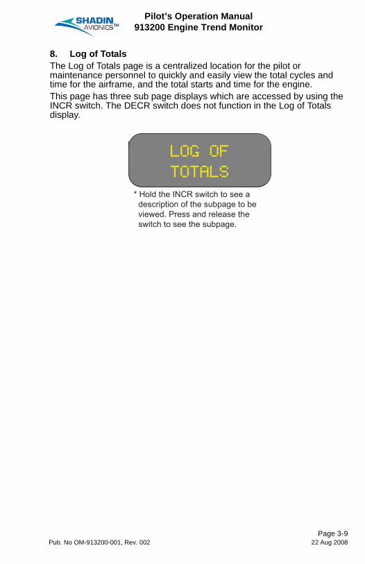
8. Log of TotalsThe Log of Totals page is a centralized location for the pilot or maintenance personnel to quickly and easily view the total cycles and time for the airframe, and the total starts and time for the engine.This page has three sub page displays which are accessed by using the INCR switch. The DECR switch does not function in the Log of Totals display.
LOG OF
TOTALS
* Hold the INCR switch to see a description of the subpage to be viewed. Press and release the switch to see the subpage.
Page 3-9Pub. No OM-913200-001, Rev. 002 22 Aug 2008

Pilot’s Operation Manual913200 Engine Trend Monitor
Each press of the INCR switch advances the display to the subpages in the following order:
AF TC/TT
0000/0000:00
AF=AirframeTC=Total CyclesTT=Total Time
# of Cycles / Hours : Minutes of Flight
TS=Total StartsTT=Total Time
# of Starts / Hours : Minutes of Flight for this Engine
L.Eng TS/TT
0000/0000:00
TS=Total StartsTT=Total Time
# of Starts / Hours : Minutes of Flight for this Engine
R.Eng TS/TT
0000/0000:00
Page 3-10Pub. No OM-913200-001, Rev. 002 22 Aug 2008
Pilot’s Operation Manual913200 Engine Trend Monitor
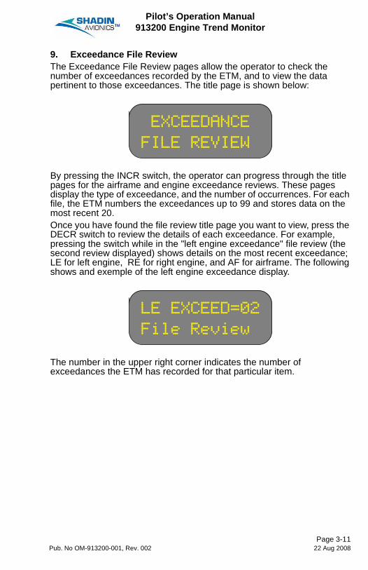
9. Exceedance File ReviewThe Exceedance File Review pages allow the operator to check the number of exceedances recorded by the ETM, and to view the data pertinent to those exceedances. The title page is shown below:
By pressing the INCR switch, the operator can progress through the title pages for the airframe and engine exceedance reviews. These pages display the type of exceedance, and the number of occurrences. For each file, the ETM numbers the exceedances up to 99 and stores data on the most recent 20.Once you have found the file review title page you want to view, press the DECR switch to review the details of each exceedance. For example, pressing the switch while in the "left engine exceedance" file review (the second review displayed) shows details on the most recent exceedance; LE for left engine, RE for right engine, and AF for airframe. The following shows and exemple of the left engine exceedance display.
The number in the upper right corner indicates the number of exceedances the ETM has recorded for that particular item.
EXCEEDANCE
FILE REVIEW
LE EXCEED=02
File Review
Page 3-11Pub. No OM-913200-001, Rev. 002 22 Aug 2008

Pilot’s Operation Manual913200 Engine Trend Monitor
The following list describes the different parts of the exceedance display. Refer to the example display given below for a visual representation of what is being described.
• The Number in the top left of the screen, indicates the order in which the exceedance took place (i.e. #02 was the second exceedance).
• The Date and Time (Local) alternately flash in the upper right corner. The time recorded is the point at which the exceedance reached its maximum value.
• The Limitation that was exceeded is shown in the lower left corner. This describes what was exceeded and gives the highest value reached (i.e. NG% 101.8 indicates that the NG exceedance peaked at 101.8%).
• The Duration, in the bottom right corner of the screen, indicates how long the given value was in exceedance. The duration is determined from the time the exceedance began, to the time the value dropped back down below the exceedance limit.
In the above example, the gas generator speed went too high, which peaked at 101.8%, and lasted 13 seconds. The exceedance was the second to occur. It happened on 5 November, 1996.If a grace period is set for the exceedance parameter, the ETM does not count the time of the grace period. Using the above example, if the system considers 101.5% the exceedance limit, and the grace period is 10 seconds, the system will not record the first ten seconds the aircraft is in exceedance of 101.5%. Therefore, if the aircraft is physically in exceedance for 23 seconds, the ETM will not count the 10 second grace period, and will display a 13 second exceedance.The ETM has a safeguard to prevent registering a false exceedance due to noise from the transducer. After the grace period has elapsed, the ETM will wait for one second to be sure the aircraft is really in exceedance. At that point the exceedance will register.
#02 05NOV96
¢%L101Ú 13S
Page 3-12Pub. No OM-913200-001, Rev. 002 22 Aug 2008
Pilot’s Operation Manual913200 Engine Trend Monitor
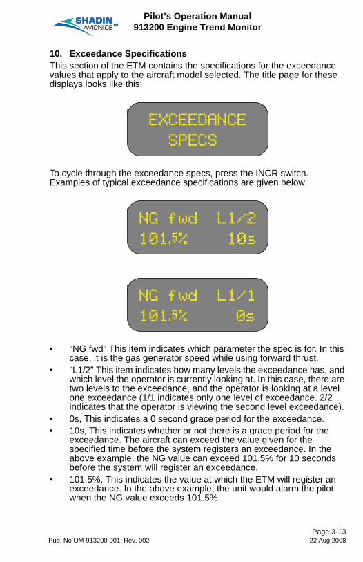
10. Exceedance SpecificationsThis section of the ETM contains the specifications for the exceedance values that apply to the aircraft model selected. The title page for these displays looks like this:
To cycle through the exceedance specs, press the INCR switch. Examples of typical exceedance specifications are given below.
• "NG fwd" This item indicates which parameter the spec is for. In this case, it is the gas generator speed while using forward thrust.
• "L1/2" This item indicates how many levels the exceedance has, and which level the operator is currently looking at. In this case, there are two levels to the exceedance, and the operator is looking at a level one exceedance (1/1 indicates only one level of exceedance. 2/2 indicates that the operator is viewing the second level exceedance).
• 0s, This indicates a 0 second grace period for the exceedance.• 10s, This indicates whether or not there is a grace period for the
exceedance. The aircraft can exceed the value given for the specified time before the system registers an exceedance. In the above example, the NG value can exceed 101.5% for 10 seconds before the system will register an exceedance.
• 101.5%, This indicates the value at which the ETM will register an exceedance. In the above example, the unit would alarm the pilot when the NG value exceeds 101.5%.
EXCEEDANCE
SPECS
NG fwd L1/2
101×% 10s
NG fwd L1/1
101×% 0s
Page 3-13Pub. No OM-913200-001, Rev. 002 22 Aug 2008

Pilot’s Operation Manual913200 Engine Trend Monitor
The following shows other possible exceedances that may be displayed:
* Based on the software in the ETM which is determined by the aircraft application,NG or N1 is displayedNP or N2 is displayedITT or TOT is displayed
IAS N1 fwd NP fwd TOT rev
ITT fwd N1 rev NP rev TOT start
ITT idle N2 fwd SHP fwd TQ fwd
ITT rev N2 rev SHP rev TQ rev
ITT start NG fwd TOT fwd
MACH NG rev TOT idle
Page 3-14Pub. No OM-913200-001, Rev. 002 22 Aug 2008

Pilot’s Operation Manual913200 Engine Trend Monitor
11. Lowest Bus Voltage / Highest ITT Values at Engine StartA major contributor to hot starts is the gradual degradation in the performance of the fuel control unit. By keeping a close watch on the maximum start temperature, the maintenance crew can more easily diagnose any degradation in the fuel control unit early on, before any serious damage can be incurred.The second major contributor to the occurrence of hot starts is a low charge on the aircraft's battery. A low battery charge results in a low bus voltage. This may cause a hot start. The ETM monitors this bus voltage during the startup procedure. The maintenance crews can then use these records to determine if the battery requires maintenance.This display has three different aspects depending on the status of the engine: before startup, during startup, and running. For example, before startup, the left engine display looks like this:
Note the "-" symbol in the middle of the upper line. This symbol indicates the condition of the engine. When a dash appears, as above, the engine is off.During start up, the left engine display changes to this:
Note that the "-" symbol has changed to a "\". This indicates that the engine is performing the start up.
The "\" symbol has now changed to a "|" symbol indicating the engine has completed the start up procedure, and is now running.
L LoV - Hi ¦
******* ****
L LoV \ Hi ¦
18Ø 688
L LoV | Hi ¦
18Ø 688
Page 3-15Pub. No OM-913200-001, Rev. 002 22 Aug 2008

Pilot’s Operation Manual913200 Engine Trend Monitor
12. Next Inspection Countdown TimerThis is an optional page that acts as a countdown timer to the aircraft's next inspection. Unless the install specifically selects this page to be shown, it will not appear in the normal cycle of pages. Time is shown in hours, minutes and seconds.
Inspection
Due200:00:00
Page 3-16Pub. No OM-913200-001, Rev. 002 22 Aug 2008
Pilot’s Operation Manual913200 Engine Trend Monitor
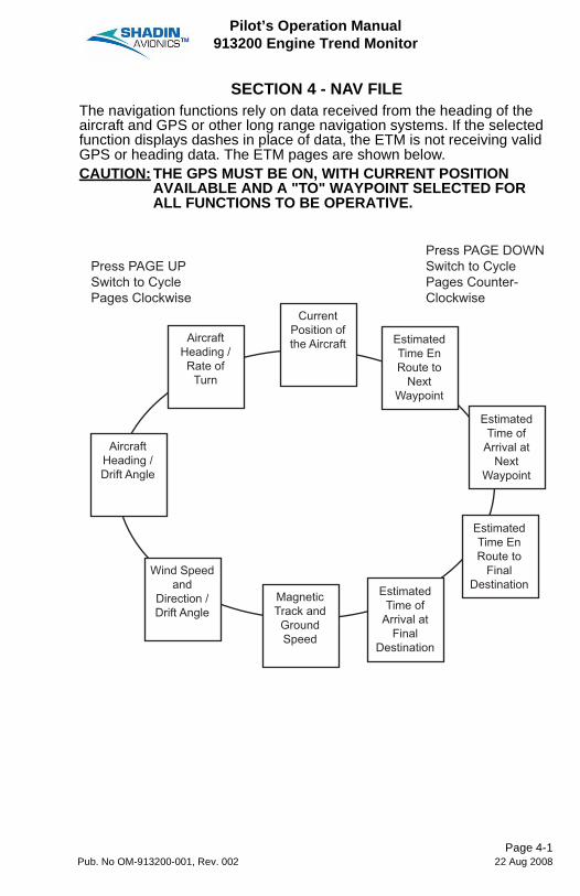
SECTION 4 - NAV FILEThe navigation functions rely on data received from the heading of the aircraft and GPS or other long range navigation systems. If the selected function displays dashes in place of data, the ETM is not receiving valid GPS or heading data. The ETM pages are shown below.CAUTION: THE GPS MUST BE ON, WITH CURRENT POSITION
AVAILABLE AND A "TO" WAYPOINT SELECTED FOR ALL FUNCTIONS TO BE OPERATIVE.
Press PAGE UPSwitch to CyclePages Clockwise
Press PAGE DOWNSwitch to CyclePages Counter-Clockwise
AircraftHeading /Drift Angle
Wind Speedand
Direction /Drift Angle
MagneticTrack andGroundSpeed
EstimatedTime of
Arrival atFinal
Destination
EstimatedTime EnRoute to
FinalDestination
EstimatedTime of
Arrival atNext
Waypoint
EstimatedTime EnRoute to
NextWaypoint
CurrentPosition ofthe AircraftAircraft
Heading /Rate of
Turn
Page 4-1Pub. No OM-913200-001, Rev. 002 22 Aug 2008

Pilot’s Operation Manual913200 Engine Trend Monitor
1. Current Position of the AircraftThe present position of the aircraft is taken directly from the NAV receiver. The system displays the aircraft position in standard latitude, longitude coordinates. For example:
2. Estimated Time En Route to Next WaypointThe estimated time en route (ETE) page contains three pieces of data:• The waypoint identifier• The estimated time en route to the current waypoint• The distance to waypoint.The waypoint identifier displays in the upper left hand corner of the screen. The estimated time en route displays on the lower right hand side, and the distance to the waypoint is just below the waypoint identifier. The display continuously updates according to changes in speed and course.
In the above example, the aircraft is flying to the Minneapolis/St. Paul International Airport. Its flight will take one hour and thirty minutes at the current ground speed.
©MSP ETE
50Ò« 1:30
Page 4-2Pub. No OM-913200-001, Rev. 002 22 Aug 2008

Pilot’s Operation Manual913200 Engine Trend Monitor
3. Estimated Time of Arrival at Next WaypointThis is the estimated time of arrival (ETA) at the next waypoint. The ETM assumes that the arrival and departure locations are in the same time zone.
In the above example, the aircraft will arrive at Minneapolis/St. Paul at 11:35 local time.4. Estimated Time En Route to Final DestinationThis display is identical to the ETE for the next waypoint, except that it displays data for the final destination, as defined by the flight plan.5. Estimated Time of Arrival at Final DestinationThis display is identical to the ETA for the next waypoint, except that it displays data for the final destination, as defined by the flight plan.6. Magnetic Track and Ground SpeedThis page shows the magnetic track, ground speed, and magnetic variation of the aircraft.
ETA > MSP
11:35 CST
MTrk012 Var
GS220ª W15Ô
Page 4-3Pub. No OM-913200-001, Rev. 002 22 Aug 2008

Pilot’s Operation Manual913200 Engine Trend Monitor
7. Wind Speed and Direction / Drift AngleThe true wind direction and speed are calculated from two different vectors: the true track/ground speed vector, and the true heading/TAS vector. Also shown in this display is the drift angle in relation to the true track. A typical Wind/Drift display looks like this:
In the above example, the wind is coming from ten degrees at twelve knots. "04L" represents the amount of drift from the magnetic track. Here the aircraft is four degrees off from its track. The "L" means that the track is to the left of the heading. (Note: wind heading is estimated to the nearest 10º, and wind speed is estimated to the nearest 5kts.) If the rate of turn exceeds three degrees per second, the wind display will turn to dashes. Once the aircraft settles onto a new course, the NAV system recalculates the data and the display will return. The process takes about thirty seconds to a minute after the aircraft completes its turn.8. Aircraft Heading / Drift AngleThis display is a combined reiteration of the aircraft heading and drift angle.
Wind/Drift
010/12ª 04L
Headng/Drift
010/ 3R
Page 4-4Pub. No OM-913200-001, Rev. 002 22 Aug 2008
Pilot’s Operation Manual913200 Engine Trend Monitor
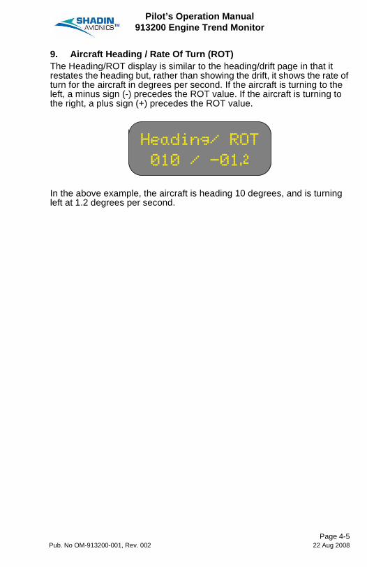
9. Aircraft Heading / Rate Of Turn (ROT)The Heading/ROT display is similar to the heading/drift page in that it restates the heading but, rather than showing the drift, it shows the rate of turn for the aircraft in degrees per second. If the aircraft is turning to the left, a minus sign (-) precedes the ROT value. If the aircraft is turning to the right, a plus sign (+) precedes the ROT value.
In the above example, the aircraft is heading 10 degrees, and is turning left at 1.2 degrees per second.
Heading/ ROT
010 / -01Ô
Page 4-5Pub. No OM-913200-001, Rev. 002 22 Aug 2008

Pilot’s Operation Manual913200 Engine Trend Monitor
Blank Page
Page 4-6Pub. No OM-913200-001, Rev. 002 22 Aug 2008
Pilot’s Operation Manual913200 Engine Trend Monitor
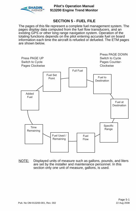
SECTION 5 - FUEL FILEThe pages of this file represent a complete fuel management system. The pages display data computed from the fuel flow transducers, and an existing GPS or other long range navigation system. Operation of the totaling functions depends on the pilot entering accurate fuel on board information each time the aircraft is refueled or defueled. The ETM pages are shown below.
NOTE: Displayed units of measure such as gallons, pounds, and liters are set by the installer and maintenance personnel. In this section only one unit of measure, gallons, is used.
Press PAGE UPSwitch to CyclePages Clockwise
Press PAGE DOWNSwitch to CyclePages Counter-Clockwise
AddedFuel
Fuel Used /Remaining
FuelFlow
SpecificRange
Fuel atDestination
TimeRemaining
Fuel toDestination
Full FuelFuel Set
Point
Page 5-1Pub. No OM-913200-001, Rev. 002 22 Aug 2008

Pilot’s Operation Manual913200 Engine Trend Monitor
1. Full FuelThis page allows the operator to enter the maximum capacity of all the fuel tanks onboard. This includes the main and auxiliary tanks.
Entering the full fuel amount is only necessary during the initial setup. The ETM stores this value in its memory, permanently.The procedure is described below:
A. Select the "Full Fuel" page.B. Press and hold both the ENTER and RECORD buttons for 10
seconds. Two chevrons will appear on the left side of the display. The system is now ready to accept input.
C. Use the INCR/DECR switch to enter the fuel amount.
D. When the correct full fuel amount is reached, press ENTER.NOTE: If the aircraft is being refueled to the full fuel value, the
fuel remaining can be quickly and easily input by pressing the ENTER button while in the "Full Fuel" page. "TAKEN" will flash briefly on the lower line.
Full Fuel
200ÒGL
Full Fuel
>> 0ÒGL
Full Fuel
>> 200ÒGL
Page 5-2Pub. No OM-913200-001, Rev. 002 22 Aug 2008

Pilot’s Operation Manual913200 Engine Trend Monitor
2. Fuel to DestinationThe fuel to destination is a calculation of how much fuel is required to reach the desired destination. It is determined by using the fuel remaining, and input from the NAV system. As an example, when the ETM is receiving NAV data, and a destination has been selected, the display shows:
If no NAV data is being received, dashes appear in place of data.3. Fuel at DestinationThe fuel at destination page displays the amount of fuel that will be onboard once the destination, as defined in the flight plan, has been reached.CAUTION: THIS CALCULATION IS BASED ONLY ON THE CURRENT
FUEL FLOW. THE ETM DOES NOT TAKE INTO ACCOUNT ANY PLANNED REDUCTION OR INCREASE IN FUEL FLOW.
This function is calculated using the current fuel consumption, and time to destination. As an example, when the ETM is receiving data from a NAV system, and a destination is selected, the display shows:
If no NAV data is being received, dashes appear in place of data.
Fuel to MSP
65Ö GAL
Fuel at MSP
134Ø GAL
Page 5-3Pub. No OM-913200-001, Rev. 002 22 Aug 2008

Pilot’s Operation Manual913200 Engine Trend Monitor
4. Specific RangeThe specific range value is useful in determining the overall performance of the aircraft under the prevailing wind conditions and the current cruise power setting. The specific range is a calculated value derived from the aircraft's ground speed, and rate of fuel consumption. Any change in the wind condition or the power setting, will be reflected in the ground speed, which in turn will affect the specific range.A strong tailwind or a lower power setting will result in a higher specific range. A strong headwind or a higher power setting will result in a lower specific range.
This display can provide a reference to determine the optimum cruise power setting to yield the best mileage under the current wind conditions. This can be done by selecting the specific range page, then adjusting the power setting until the optimum value has been reached. The power adjustments should be done in small increments and roughly two minutes apart from each other. This pause allows enough time for the GPS to stabilize the ground speed.5. Fuel FlowThis page displays the current rate of fuel flow for the engine(s). It is measured by the fuel flow transducer and is displayed.
Spcfic Range
2.30NM/GAL
F/Flow GPH
L 20Ò R 20Ò
Gallons per Hour
Page 5-4Pub. No OM-913200-001, Rev. 002 22 Aug 2008

Pilot’s Operation Manual913200 Engine Trend Monitor
6. Fuel Used / Remaining (total)This page displays the total amount of fuel used and the total amount of fuel remaining in the units currently selected.
These values are automatically calculated by the system based on the rate of fuel flow and the fuel amounts entered by the pilot at the beginning of the flight. It is possible, however, to manually change the fuel remaining value if the plane has been defueled.The following procedure tells how to decrease the fuel onboard from the Fuel Used / Remaining page.
A. Select the "Fuel File" using the rotary switch.B. Select "fuel remaining" page.C. Use INCR/DECR switch to change the fuel amount. A *
replaces the / while the value is being changed.D. When the correct onboard remaining fuel amount is reached,
press ENTER.7. Fuel Used (per engine)This page displays the amount of fuel used by the engine(s) in the units currently selected. It is important that this page is not confused with the previous page which displays the total amount of fuel used rather than the fuel used by the engine(s).
F/Use 108ÖGL
F/Rem 68×GL
L/Use 54ÛGL
R/Use 53×GL
Page 5-5Pub. No OM-913200-001, Rev. 002 22 Aug 2008

Pilot’s Operation Manual913200 Engine Trend Monitor
8. Time RemainingThis page displays the flight time remaining based on current fuel flow rate. In addition, the total amount of fuel remaining is displayed on the second line.
In the above example, the aircraft has about five hours of flight time, and one hundred gallons of fuel remaining.9. Added FuelThis page allows for the input of the amount of fuel added onboard the aircraft. This is often useful if a small amount of fuel is added after the fuel onboard has been entered.This value is limited to less than or equal to the full fuel amount. For example, suppose the full fuel capacity is 120 gallons, and the aircraft has 100 gallons onboard. The added fuel value cannot be more than 20 gallons.
The entry procedure is as follows:A. Select the Fuel File using the rotary switch.B. Use the PAGE UP/DOWN switch to select the fuel added page.C. Use the INCR/DECR switch to enter the added fuel amount.D. When the correct fuel amount is reached, press ENTER.
T/Rem 5:04HR
F/Rem 100GL
Added Fuel
0ÒGL
Page 5-6Pub. No OM-913200-001, Rev. 002 22 Aug 2008
Pilot’s Operation Manual913200 Engine Trend Monitor
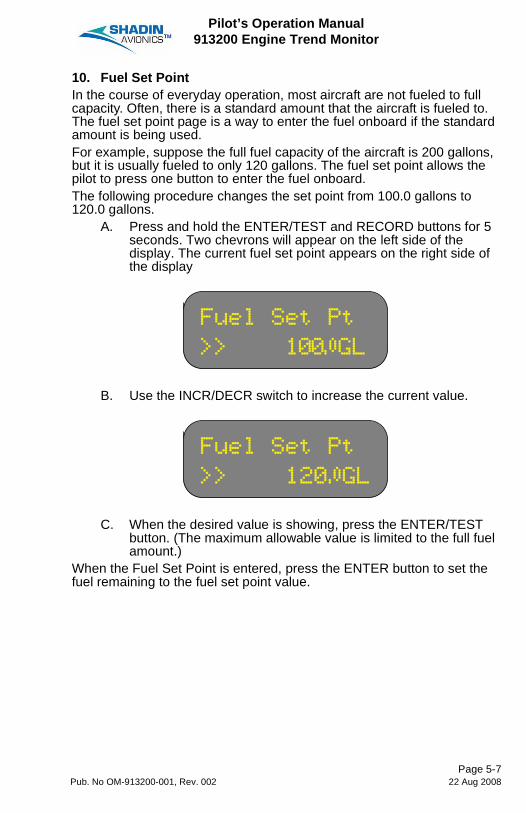
10. Fuel Set PointIn the course of everyday operation, most aircraft are not fueled to full capacity. Often, there is a standard amount that the aircraft is fueled to. The fuel set point page is a way to enter the fuel onboard if the standard amount is being used.For example, suppose the full fuel capacity of the aircraft is 200 gallons, but it is usually fueled to only 120 gallons. The fuel set point allows the pilot to press one button to enter the fuel onboard.The following procedure changes the set point from 100.0 gallons to 120.0 gallons.
A. Press and hold the ENTER/TEST and RECORD buttons for 5 seconds. Two chevrons will appear on the left side of the display. The current fuel set point appears on the right side of the display
B. Use the INCR/DECR switch to increase the current value.
C. When the desired value is showing, press the ENTER/TEST button. (The maximum allowable value is limited to the full fuel amount.)
When the Fuel Set Point is entered, press the ENTER button to set the fuel remaining to the fuel set point value.
Fuel Set Pt
>> 100ÒGL
Fuel Set Pt
>> 120ÒGL
Page 5-7Pub. No OM-913200-001, Rev. 002 22 Aug 2008

Pilot’s Operation Manual913200 Engine Trend Monitor
Blank Page
Page 5-8Pub. No OM-913200-001, Rev. 002 22 Aug 2008

Pilot’s Operation Manual913200 Engine Trend Monitor
SECTION 6 - AIRDATA FILEThe Air Data pages display information from the pitot/static system and an external OAT probe. The ETM pages are shown below.
NOTE: Displayed units of measure such as pounds and kilograms for gross weight are set by the installer and maintenance personnel. In this section only one unit of measure, pounds, is used.
Press PAGE UPSwitch to CyclePages Clockwise
Press PAGE DOWNSwitch to CyclePages Counter-Clockwise
IAS, TAS,and
Mach
OAT andDensityAltitude*
FlightTimer
GreenwichMean Time
PressureAltitude and
DensityAltitude
Date andLocal Time
GrossWeight
*The page is OAT and SATon some aircraft installations
Page 6-1Pub. No OM-913200-001, Rev. 002 22 Aug 2008

Pilot’s Operation Manual913200 Engine Trend Monitor
1. Date and Local TimeThis page displays the date and local time.
2. Greenwich Mean TimeThis page displays the Greenwich Mean Time. Display of this page is enabled/disabled by the installer and maintenance personnel. This value is calculated from the local time.
3. Flight TimerThe flight timer shows the time that the aircraft is in flight. The timer takes its queues to start and stop from the IAS. It begins running when the IAS is greater than the takeoff threshold value and stops running when IAS drops below the landing threshold value. The takeoff threshold and landing threshold values are in software specific to the aircraft.The flight duration is recorded on the output device in the landing report. The flight timer does not record the time for take-off or landing, only the duration of the flight.CAUTION: IF THE PILOT ENTERS THE DATA ENTRY MODE WHILE
IN FLIGHT, THE FLIGHT TIMER RESETS TO ZERO.The flight timer displays hours, minutes, and seconds.
In the above example, the aircraft has been flying for four hours, fourteen minutes, and thirty two seconds.
FRI 16 AUG96
11:02:26 CST
TIME
16:11:42 GMT
FLIGHT TIMER
04:14:32
Page 6-2Pub. No OM-913200-001, Rev. 002 22 Aug 2008
Pilot’s Operation Manual913200 Engine Trend Monitor
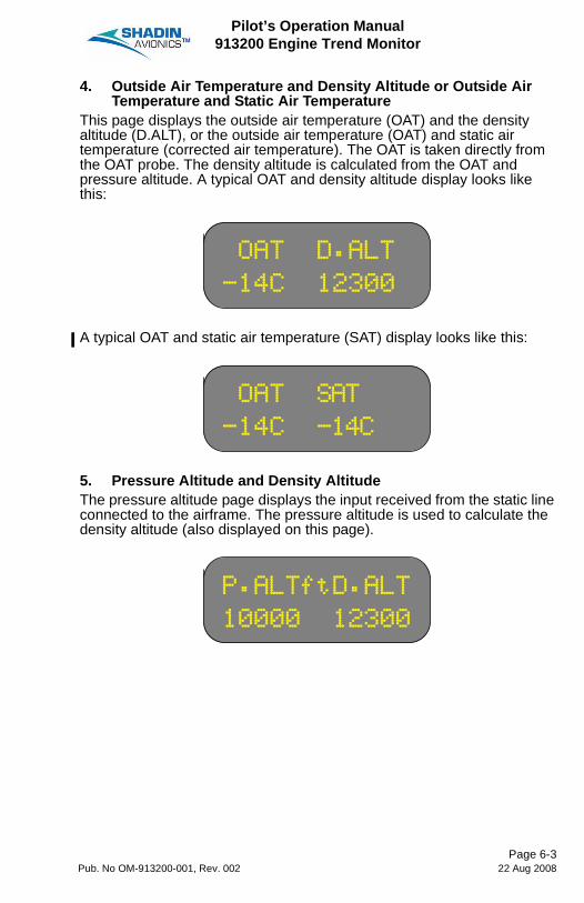
4. Outside Air Temperature and Density Altitude or Outside Air Temperature and Static Air Temperature
This page displays the outside air temperature (OAT) and the density altitude (D.ALT), or the outside air temperature (OAT) and static air temperature (corrected air temperature). The OAT is taken directly from the OAT probe. The density altitude is calculated from the OAT and pressure altitude. A typical OAT and density altitude display looks like this:
A typical OAT and static air temperature (SAT) display looks like this:
5. Pressure Altitude and Density AltitudeThe pressure altitude page displays the input received from the static line connected to the airframe. The pressure altitude is used to calculate the density altitude (also displayed on this page).
OAT D.ALT
-14C 12300
OAT SAT
-14C -14C
P.ALTftD.ALT
10000 12300
Page 6-3Pub. No OM-913200-001, Rev. 002 22 Aug 2008
Pilot’s Operation Manual913200 Engine Trend Monitor
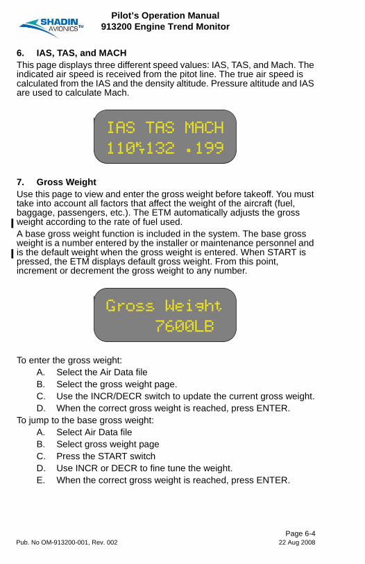
6. IAS, TAS, and MACHThis page displays three different speed values: IAS, TAS, and Mach. The indicated air speed is received from the pitot line. The true air speed is calculated from the IAS and the density altitude. Pressure altitude and IAS are used to calculate Mach.
7. Gross WeightUse this page to view and enter the gross weight before takeoff. You must take into account all factors that affect the weight of the aircraft (fuel, baggage, passengers, etc.). The ETM automatically adjusts the gross weight according to the rate of fuel used.A base gross weight function is included in the system. The base gross weight is a number entered by the installer or maintenance personnel and is the default weight when the gross weight is entered. When START is pressed, the ETM displays default gross weight. From this point, increment or decrement the gross weight to any number.
To enter the gross weight:A. Select the Air Data fileB. Select the gross weight page.C. Use the INCR/DECR switch to update the current gross weight.D. When the correct gross weight is reached, press ENTER.
To jump to the base gross weight:A. Select Air Data fileB. Select gross weight pageC. Press the START switchD. Use INCR or DECR to fine tune the weight.E. When the correct gross weight is reached, press ENTER.
IAS TAS MACH
110ª132 .199
Gross Weight
7600LB
Page 6-4Pub. No OM-913200-001, Rev. 002 22 Aug 2008

Pilot’s Operation Manual913200 Engine Trend Monitor
SECTION 7 - AUTOMATIC FUNCTIONSCertain functions are performed independently of user settings and automatically displayed at the appropriate time by the ETM. These include:• Power Checks• Exceedance Alarms• Popup Messages• Output Reports1. Power CheckA power check is a data sampling performed by the ETM for use by the Pratt & Whitney ECTM program. The ECTM program uses power checks to measure and graph deviations from an established norm in the NG, ITT, and fuel flow. This deviation gives a clear indication of the engine condition.For the ETM to perform a power check, the aircraft must be cruising at a stable altitude and speed. After a preset time flying at those stable values, the ETM will automatically perform a power check at the interval set by the installer.2. Exceedance AlarmsAn exceedance is a condition the aircraft can enter into if any of the monitored parameters have a value greater than the FAA approved flight manual limitations and the manufacturer's limits. The ETM constantly watches the engines and airframe for exceedances.An exceedance is always recorded by the system, however, the installer and maintenance personnel can disable the display of exceedances during normal operation.If the exceedance display option is enabled, each time an exceedance occurs, the current display will be overridden by the exceedance display. As long as the display remains flashing, the aircraft is still in exceedance. When the parameter that is in exceedance has become less then the threshold limit, the display stops flashing. At this point, the exceedance must be acknowledged by the pilot. To acknowledge an exceedance, press the DECR switch.
Page 7-1Pub. No OM-913200-001, Rev. 002 22 Aug 2008

Pilot’s Operation Manual913200 Engine Trend Monitor
3. POPUP MESSAGESThe popup message function is designed to alert the pilot or operator of system errors and for notification of particular events.
A. This example shows that the key recorder is physically disconnected from the ETM.
B. This example shows that the key recorder does not have a key inserted.
C. This example shows that the key has been filled to 80% or more.
D. This example shows that the power check was logged. This display shows power check is set by the installer to one per flight or one per day.
Key Recorder
Disconnected
Key
Not Inserted
Key 92Ø%used
Advisory
Power check
Completed
Page 7-2Pub. No OM-913200-001, Rev. 002 22 Aug 2008

Pilot’s Operation Manual913200 Engine Trend Monitor
E. This example shows that internal clock has failed.
Clock
Corrupted
Page 7-3Pub. No OM-913200-001, Rev. 002 22 Aug 2008

Pilot’s Operation Manual913200 Engine Trend Monitor
Blank Page
Page 7-4Pub. No OM-913200-001, Rev. 002 22 Aug 2008

Pilot’s Operation Manual913200 Engine Trend Monitor
SECTION 8 - AUXILIARY FUNCTIONSThe system has the following additional capabilities that do not apply to any of the four files or their related pages. They function independently of the various modes and files.1. StopwatchThe stopwatch function is accessed from any page in normal operational mode. Press the RESET button and the following page displays.
Press START/STOP switch to operate the stopwatch. The RESET button resets the timer. Use the PAGE/UP DOWN or rotary switch to return to the main display functions.2. Self TestTo do a self-test the engines must be off. If an engine is running, the self-test feature will not function. Press and hold the ENTER/TEST button for about 5 seconds start the self test. "SYSTEM TEST" flashes on the screen followed by the aircraft model. The unit will then begin checking its inputs channels. If any channel fails, the system notifies the operator. For example:
"CHECK FF L" indicates a bad fuel flow input channel for the left engine. Other possible error messages are listed below:
5V rev FF L N1 R
6.9V ref GROUND N2 L
8V ref N1 L No 19200Hz
10V ref
STOP WATCH
* 00:00:00 *
CHECK
FF L
Page 8-1Pub. No OM-913200-001, Rev. 002 22 Aug 2008

Pilot’s Operation Manual913200 Engine Trend Monitor
The following message shows that all tests passed.
ALL TESTS
PASSED
Page 8-2Pub. No OM-913200-001, Rev. 002 22 Aug 2008

Pilot’s Operation Manual913200 Engine Trend Monitor
SECTION 9 - PARAMETER RECORDIf the aircraft needs maintenance because of inaccurate parameter readings, record the ETM and indicator parameter values on a copy of the following table. Give the record to the maintenance personnel for an aid to fault isolation.
Parameters
Parameter
ETM Value Indicator Value
Left (or Single) Right
Left (or Single) Right
Gas Generator Speed (NG)
Inter-Turbine Temperature (ITT)
Torque (TQ)
Propeller Speed (NP)
Fuel Flow
Altitude
Airspeed
OAT
Heading
Page 9-1Pub. No OM-913200-001, Rev. 002 22 Aug 2008

Pilot’s Operation Manual913200 Engine Trend Monitor
Blank Page
Page 9-2Pub. No OM-913200-001, Rev. 002 22 Aug 2008


6831 OXFORD STREETST. LOUIS PARK, MN 55426
U.S.A.
SALES: (800) 328-0584TECHNICAL SUPPORT: (800) 338-2849
Copyright 2008 Shadin LP (d/b/a Shadin Avionics)