
8900NET (Net Card) Network Interface Module v4.2.0 - Grass Valley
106
8900NET NETWORK INTERFACE MODULE Instruction Manual SOFTWARE VERSION 4.2.0 071061205 NOVEMBER 2007
Transcript of 8900NET (Net Card) Network Interface Module v4.2.0 - Grass Valley

8900NETNETWORK INTERFACE MODULE
Instruction Manual
SOFTWARE VERSION 4.2.0
071061205NOVEMBER 2007

Affiliate with the N.V. KEMA in The Netherlands
CERTIFICATECertificate Number: 510040.001
The Quality System of:
Grass Valley, Inc. 400 Providence Mine Road Nevada City, CA 95945 United States
15655 SW Greystone Ct. Beaverton, OR 97006 United States
10 Presidential Way 3rd Floor, Suite 300 Woburn, MA 01801 United States
Nederland B.V. 4800 RP BREDA The Netherlands
Weiterstadt, Germany Brunnenweg 9 D-64331 Weiterstadt Germany
Rennes, France Rue du Clos Courtel Cesson-Sevigne, Cedex France
Technopole Brest Iroise CS 73808 29238 Brest Cedex 3 France
17 rue du Petit Albi-BP 8244 95801 Cergy Pontoise Cergy, France
2300 South Decker Lake Blvd. Salt Lake City, UT 84119 United States
7140 Baymeadows Way Suite 101 Jacksonville, FL 32256 United States
Including its implementation, meets the requirements of the standard:
ISO 9001:2000 Scope:The design, manufacture and support of video hardware and software products and related systems.
This Certificate is valid until: June 14, 2009 This Certificate is valid as of: August 30, 2006 Certified for the first time: June 14, 2000
H. Pierre Sallé President KEMA-Registered Quality
The method of operation for quality certification is defined in the KEMA General Terms And Conditions For Quality And Environmental Management Systems Certifications. Integral publication of this certificate is allowed.
KEMA-Registered Quality, Inc.4377 County Line Road Chalfont, PA 18914 Ph: (215)997-4519 Fax: (215)997-3809 CRT 001 073004
Accredited By:ANAB
8900NETNETWORK INTERFACE MODULE
Instruction Manual
SOFTWARE VERSION 4.2.0
071061205NOVEMBER 2007

4 8900NET — Instruction Manual
Contacting Grass Valley
Copyright © Grass Valley. All rights reserved.This product may be covered by one or more U.S. and foreign patents.
Grass Valley Web Site The www.thomsongrassvalley.com web site offers the following:
Online User Documentation — Current versions of product catalogs, brochures, data sheets, ordering guides, planning guides, manuals, and release notes in .pdf format can be downloaded.
FAQ Database — Solutions to problems and troubleshooting efforts can be found by searching our Frequently Asked Questions (FAQ) database.
Software Downloads — Download software updates, drivers, and patches.
InternationalSupport Centers
France24 x 7
+800 8080 2020 or +33 1 48 25 20 20+800 8080 2020 or +33 1 48 25 20 20
United States/Canada24 x 7 +1 800 547 8949 or +1 530 478 4148
Local Support Centers
(available during normal
business hours)
AsiaHong Kong, Taiwan, Korea, Macau: +852 2531 3058 Indian Subcontinent: +91 22 24933476Southeast Asia/Malaysia: +603 7805 3884 Southeast Asia/Singapore: +65 6379 1313China: +861 0660 159 450 Japan: +81 3 5484 6868
Australia and New Zealand: +61 1300 721 495 Central/South America: +55 11 5509 3443
Middle East: +971 4 299 64 40 Near East and Africa: +800 8080 2020 or +33 1 48 25 20 20
Europe
Belarus, Russia, Tadzikistan, Ukraine, Uzbekistan: +7 095 2580924 225 Switzerland: +41 1 487 80 02S. Europe/Italy-Roma: +39 06 87 20 35 28 -Milan: +39 02 48 41 46 58 S. Europe/Spain: +34 91 512 03 50Benelux/Belgium: +32 (0) 2 334 90 30 Benelux/Netherlands: +31 (0) 35 62 38 42 1 N. Europe: +45 45 96 88 70Germany, Austria, Eastern Europe: +49 6150 104 444 UK, Ireland, Israel: +44 118 923 0499

Preface
About This ManualThis manual describes the features of a specific 8900 module in the Gecko and GeckoFlex Signal Processing System families As part of this module family, it is subject to Safety and Regulatory Compliance described in the Gecko 8900 Series frame and power supply documentation (see the Gecko 8900 Frames and the GeckoFlex Frames Instruction Manuals
8900NET — Instruction Manual 5

Preface
6 8900NET — Instruction Manual
ContentsPreface. . . . . . . . . . . . . . . . . . . . . . . . . . . . . . . . . . . . . . . . . . . . . . . . . . . . . . . . . . . . . . . . . . . . . 5
About This Manual . . . . . . . . . . . . . . . . . . . . . . . . . . . . . . . . . . . . . . . . . . . . . . . . . . . . . 5
8900NET Network Interface (Net Card) Module. . . . . . . . . . . . . . . . . . . . . . . . . 9Introduction . . . . . . . . . . . . . . . . . . . . . . . . . . . . . . . . . . . . . . . . . . . . . . . . . . . . . . . . . . . 9
8900NET Features . . . . . . . . . . . . . . . . . . . . . . . . . . . . . . . . . . . . . . . . . . . . . . . . . . . . 9Remote Control Panels . . . . . . . . . . . . . . . . . . . . . . . . . . . . . . . . . . . . . . . . . . . . . . . 10Basic Network Design. . . . . . . . . . . . . . . . . . . . . . . . . . . . . . . . . . . . . . . . . . . . . . . . 10
Installation . . . . . . . . . . . . . . . . . . . . . . . . . . . . . . . . . . . . . . . . . . . . . . . . . . . . . . . . . . . 118900NET Module Alarm DIP Switches . . . . . . . . . . . . . . . . . . . . . . . . . . . . . . . . . 11Module Placement in the Gecko 8900 and GeckoFlex Frame . . . . . . . . . . . . . . . 12Cabling . . . . . . . . . . . . . . . . . . . . . . . . . . . . . . . . . . . . . . . . . . . . . . . . . . . . . . . . . . . . 14
RS-232 Communication Port . . . . . . . . . . . . . . . . . . . . . . . . . . . . . . . . . . . . . . . . 15Ethernet Cable . . . . . . . . . . . . . . . . . . . . . . . . . . . . . . . . . . . . . . . . . . . . . . . . . . . . 18
Power Up . . . . . . . . . . . . . . . . . . . . . . . . . . . . . . . . . . . . . . . . . . . . . . . . . . . . . . . . . . . . 208900NET Module Indicator LEDs . . . . . . . . . . . . . . . . . . . . . . . . . . . . . . . . . . . . . . 21
Establishing Frame Network Identity . . . . . . . . . . . . . . . . . . . . . . . . . . . . . . . . . . . . 22NetConfig Application . . . . . . . . . . . . . . . . . . . . . . . . . . . . . . . . . . . . . . . . . . . . . . . 22Good Networking Practices . . . . . . . . . . . . . . . . . . . . . . . . . . . . . . . . . . . . . . . . . . . 22Setting Frame Network Identity . . . . . . . . . . . . . . . . . . . . . . . . . . . . . . . . . . . . . . . 23Network Configuration Storage . . . . . . . . . . . . . . . . . . . . . . . . . . . . . . . . . . . . . . . 25
Web Browser Setup. . . . . . . . . . . . . . . . . . . . . . . . . . . . . . . . . . . . . . . . . . . . . . . . . . . . 25Web Browser Notes. . . . . . . . . . . . . . . . . . . . . . . . . . . . . . . . . . . . . . . . . . . . . . . . . . 26Addressing the Frame URL . . . . . . . . . . . . . . . . . . . . . . . . . . . . . . . . . . . . . . . . . . . 26
Default MAC (machine) Address . . . . . . . . . . . . . . . . . . . . . . . . . . . . . . . . . . . . 26Status Monitoring and Reporting . . . . . . . . . . . . . . . . . . . . . . . . . . . . . . . . . . . . . . . . 27
External Frame Alarm. . . . . . . . . . . . . . . . . . . . . . . . . . . . . . . . . . . . . . . . . . . . . . . . 28Module Health Bus Reporting . . . . . . . . . . . . . . . . . . . . . . . . . . . . . . . . . . . . . . . 28
LED Status Reporting . . . . . . . . . . . . . . . . . . . . . . . . . . . . . . . . . . . . . . . . . . . . . . . . 30Web Browser Status Reporting . . . . . . . . . . . . . . . . . . . . . . . . . . . . . . . . . . . . . . . . 31SNMP Monitoring . . . . . . . . . . . . . . . . . . . . . . . . . . . . . . . . . . . . . . . . . . . . . . . . . . . 32
Using the 8900NET GUI. . . . . . . . . . . . . . . . . . . . . . . . . . . . . . . . . . . . . . . . . . . . . . . . 348900 Frame GUI Interface. . . . . . . . . . . . . . . . . . . . . . . . . . . . . . . . . . . . . . . . . . . . . 34
Frame Status Page . . . . . . . . . . . . . . . . . . . . . . . . . . . . . . . . . . . . . . . . . . . . . . . . . 34Older 8900 Module Support . . . . . . . . . . . . . . . . . . . . . . . . . . . . . . . . . . . . . . . . . 37Frame Configuration Web Page . . . . . . . . . . . . . . . . . . . . . . . . . . . . . . . . . . . . . 39Frame Connections Web Page . . . . . . . . . . . . . . . . . . . . . . . . . . . . . . . . . . . . . . . 41Frame Alarm Reporting Web Page . . . . . . . . . . . . . . . . . . . . . . . . . . . . . . . . . . . 42LED Reporting Web Page . . . . . . . . . . . . . . . . . . . . . . . . . . . . . . . . . . . . . . . . . . . 48SNMP Reporting Web Page . . . . . . . . . . . . . . . . . . . . . . . . . . . . . . . . . . . . . . . . . 50Power Supply/Demand Web Page. . . . . . . . . . . . . . . . . . . . . . . . . . . . . . . . . . . 52Frame Power Supply Web Pages. . . . . . . . . . . . . . . . . . . . . . . . . . . . . . . . . . . . . 55
8900NET Module Interface . . . . . . . . . . . . . . . . . . . . . . . . . . . . . . . . . . . . . . . . . . . 568900NET Module Status Web Page. . . . . . . . . . . . . . . . . . . . . . . . . . . . . . . . . . . 56
8900NET — Instruction Manual 7
Contents
8900NET Module Configuration Web Page . . . . . . . . . . . . . . . . . . . . . . . . . . . 578900NET Network Web Page . . . . . . . . . . . . . . . . . . . . . . . . . . . . . . . . . . . . . . . 61Media Module Slot Configuration . . . . . . . . . . . . . . . . . . . . . . . . . . . . . . . . . . . 62
Upgrading 8900NET Software . . . . . . . . . . . . . . . . . . . . . . . . . . . . . . . . . . . . . . . . 64Acquiring Module Software Updates . . . . . . . . . . . . . . . . . . . . . . . . . . . . . . . . 64
Service . . . . . . . . . . . . . . . . . . . . . . . . . . . . . . . . . . . . . . . . . . . . . . . . . . . . . . . . . . . . . . 65Troubleshooting GUI Operation . . . . . . . . . . . . . . . . . . . . . . . . . . . . . . . . . . . . . . . . 66
LogPrint Procedure From Gecko/GeckoFlex Frame. . . . . . . . . . . . . . . . . . . . . . 73Functional Description . . . . . . . . . . . . . . . . . . . . . . . . . . . . . . . . . . . . . . . . . . . . . . . . 78
Temperature Sensing . . . . . . . . . . . . . . . . . . . . . . . . . . . . . . . . . . . . . . . . . . . . . . . . 78ROM and RAM . . . . . . . . . . . . . . . . . . . . . . . . . . . . . . . . . . . . . . . . . . . . . . . . . . . . . 79Ethernet Port . . . . . . . . . . . . . . . . . . . . . . . . . . . . . . . . . . . . . . . . . . . . . . . . . . . . . . . 79RS-232 Serial Port . . . . . . . . . . . . . . . . . . . . . . . . . . . . . . . . . . . . . . . . . . . . . . . . . . . 79Module Health Bus. . . . . . . . . . . . . . . . . . . . . . . . . . . . . . . . . . . . . . . . . . . . . . . . . . 79Frame Bus . . . . . . . . . . . . . . . . . . . . . . . . . . . . . . . . . . . . . . . . . . . . . . . . . . . . . . . . . 79Module Present Detection . . . . . . . . . . . . . . . . . . . . . . . . . . . . . . . . . . . . . . . . . . . . 79Fan Speed Control and Monitor . . . . . . . . . . . . . . . . . . . . . . . . . . . . . . . . . . . . . . . 80On-board Regulator . . . . . . . . . . . . . . . . . . . . . . . . . . . . . . . . . . . . . . . . . . . . . . . . . 80
Specifications. . . . . . . . . . . . . . . . . . . . . . . . . . . . . . . . . . . . . . . . . . . . . . . . . . . . . . . . . 81
Appendix . . . . . . . . . . . . . . . . . . . . . . . . . . . . . . . . . . . . . . . . . . . . . . . . . . . . . . . . . . . . . . . . . 83Compatibility Matrix . . . . . . . . . . . . . . . . . . . . . . . . . . . . . . . . . . . . . . . . . . . . . . . . . . 83
Control and Monitoring Support . . . . . . . . . . . . . . . . . . . . . . . . . . . . . . . . . . . . . . 86Control and Monitoring Notes . . . . . . . . . . . . . . . . . . . . . . . . . . . . . . . . . . . . . . . . 868900–FLOAD–CBL Assembly . . . . . . . . . . . . . . . . . . . . . . . . . . . . . . . . . . . . . . . . . 86
8900NET Software Update From FTP Server. . . . . . . . . . . . . . . . . . . . . . . . . . . . . . 87FTP Method Overview. . . . . . . . . . . . . . . . . . . . . . . . . . . . . . . . . . . . . . . . . . . . . . . 87FTP Software Update Procedure . . . . . . . . . . . . . . . . . . . . . . . . . . . . . . . . . . . . . . 88
Password Protection for Software Upgrades . . . . . . . . . . . . . . . . . . . . . . . . . . 96Upgrading Software . . . . . . . . . . . . . . . . . . . . . . . . . . . . . . . . . . . . . . . . . . . . . . . 97
Unsupported Software Updates. . . . . . . . . . . . . . . . . . . . . . . . . . . . . . . . . . . . . . 102
Index . . . . . . . . . . . . . . . . . . . . . . . . . . . . . . . . . . . . . . . . . . . . . . . . . . . . . . . . . . . . . . . . . . . . . 103
8 8900NET — Instruction Manual

8900NET Network Interface (Net Card) Module
IntroductionThe 8900NET Network Interface module (Net Card) provides control and monitor access to the Gecko 8900 and GeckoFlex frames and the audio/video media modules in the frames through a web browser graph-ical user interface (GUI), the Newton Control Panel, and SNMP manage-ment applications.
Note Refer to the 8900 Gecko Frames or GeckoFlex Frames Instruction Manuals for more specific frame information.
8900NET FeaturesThe 8900NET module features:
• 10 Base-T Ethernet interface,
• Fan front cover power and control,
• Support for the following:
• Software update downloading
• Newton Modular Control system control panels
• Frame Alarm connector on rear of module
• Asset Tag identification
• HTML protocol
• Simple Network Management Protocol (SNMP) monitoring
• NetConfig Networking Configuration application
8900NET—Instruction Manual 9
Introduction
Remote Control PanelsThe 8900NET module with version 3.2.0 or later software allows the frame to be remotely controlled by the Newton Control Panel via the Ethernet port. Refer to the Newton Control Panel documentation for details.
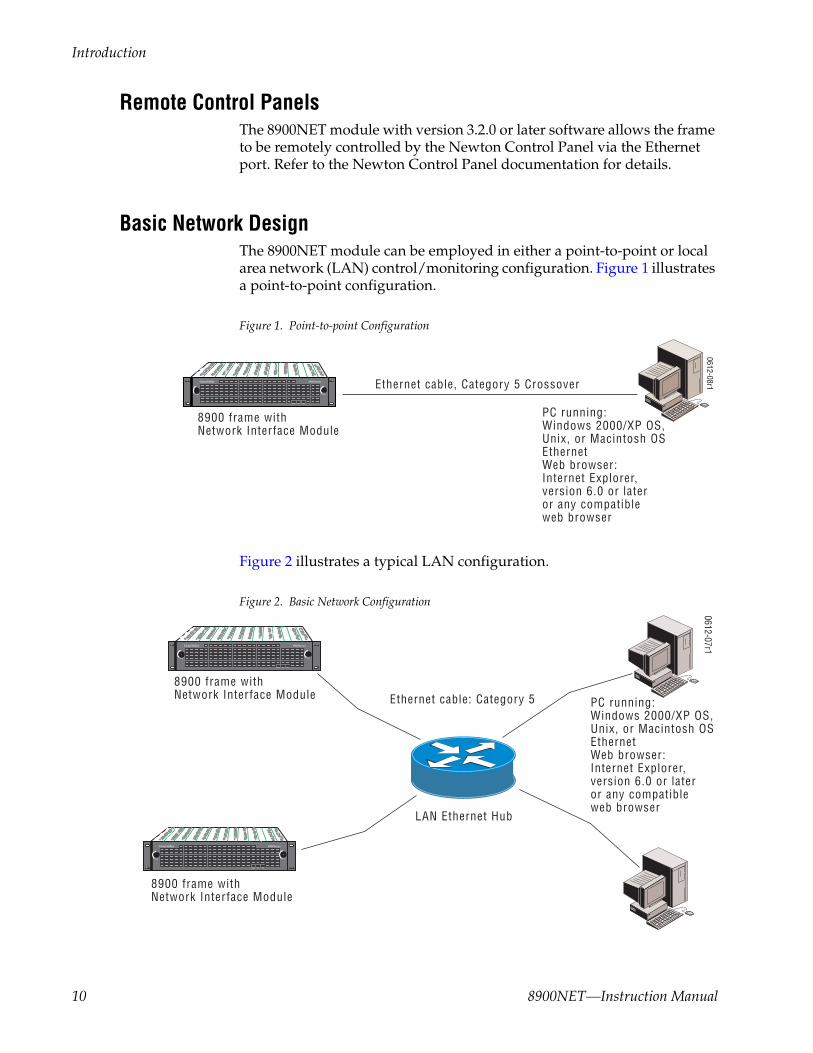
Basic Network DesignThe 8900NET module can be employed in either a point-to-point or local area network (LAN) control/monitoring configuration. Figure 1 illustrates a point-to-point configuration.
Figure 1. Point-to-point Configuration
Figure 2 illustrates a typical LAN configuration.
Figure 2. Basic Network Configuration
0612-08r1
PC runn ing:Windows 2000/XP OS,Un ix, or Macintosh OSEthernetWeb browser:Internet Explorer, vers ion 6.0 or lateror any compatible web browser
Ethernet cable, Category 5 Crossover
8900 frame with Network Inter face Modu le
PS 1 PS 2
LOCKLOCK
FAULT
0612-07r1
LAN Ethernet Hub
8900 frame with Network Inter face Modu le
PS 1 PS 2
LOCKLOCK
FAULT
8900 frame with Network Inter face Modu le
PS 1 PS 2
LOCKLOCK
FAULT
Ethernet cable: Category 5 PC runn ing:Windows 2000/XP OS,Un ix, or Macintosh OSEthernetWeb browser:Internet Explorer, vers ion 6.0 or lateror any compatible web browser
10 8900NET—Instruction Manual

Installation
InstallationThis section describes placing the module in Gecko 8900 and GeckoFlex frames and cabling the communications ports for all frame types. Proce-dures for DIP switch settings, installation, and cabling of the module are described in this section.
An 8900NET module will come installed in Gecko 8900TF/TFN and GeckoFlex 8900FF/FFN frames. Note that there are two DIP switches described below that will affect reporting to the 8900NET module, the external RS-232 Frame Alarm, and the SNMP reporting system.
Note The GeckoFlex frame requires an 8900NET module running 4.0.0 or later software.
8900NET Module Alarm DIP SwitchesThere are two eight-position DIP switches (S1 and S2) on the 8900NET module for enabling or disabling the overall status reporting of the frame and modules. Figure 3 illustrates the DIP switches set with the factory defaults and Table 1 on page 12 gives the function of each DIP switch set-ting. You may enable or disable reporting functions from this point.
Note Some web page and frame alarm and SNMP reporting functions must be enabled on the DIP switches to be functional.
Figure 3. Alarm Reporting DIP Switches (Defaults Shown)
The current status of the DIP switch settings is always reported on the 8900NET Status (page 56), Frame Alarm Reporting (page 42), LED Reporting (page 49), and SNMP Reporting (page 48) frame web pages. You may check DIP switch status on these web pages instead of pulling out the module.
Refer to Figure 12 on page 20 for the location of S1 and S2 on the 8900NET module and Table 2 on page 21 for the possible settings. A settings table is also silk-screened on the bottom of the module. Disabling (or filtering) of fault reports can sometimes be useful in isolating problems in the frame.
12
34
56
78
12
34
56
78
S2S1
Power Supply #1Power Supply #2
Temperature (not used)Fan
ModuleFrame BusFan Speed
NM Control
Status
8900NET
IP AddressFrame Control
RemoteOverride
LED
0612
_28r
2
8900NET—Instruction Manual 11

Installation
Note Disabled faults are still detected by the network GUI but LEDs will be inactive.
Refer to Status Monitoring and Reporting on page 27, for an overview of overall status reporting from the Gecko and GeckoFlex frames, 8900NET, power supplies, and media modules in the frame.
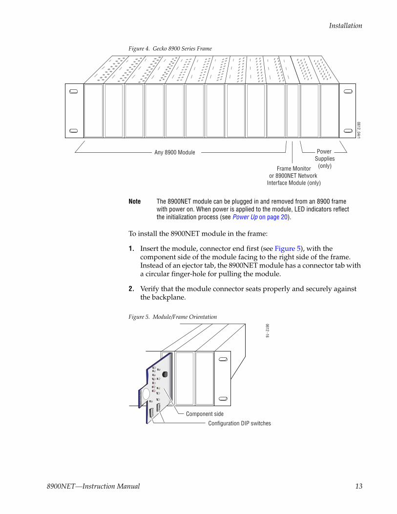
Module Placement in the Gecko 8900 and GeckoFlex FrameThere are ten cell locations in the frame to accommodate media modules. These are the left ten locations. Refer to Figure 4 (Gecko 8900 frame shown with no cover).
The two cells on the right are allocated for the power supplies. For addi-tional information concerning the Power Supply modules, refer to the 8900 Frames Instruction Manual and the GeckoFlex Frames Instruction Manual.
Note Gecko and GeckoFlex frames do not use the same power supply. Refer to Power Supply/Demand Web Page on page 52.
The third cell from the right is allocated for the 8900NET Network Interface or Frame Monitor module (GeckoFlex 8900FF and Gecko 8900TF-V/A). For additional information concerning the Frame Monitor module, refer to the 8900 Frames Instruction Manual or the GeckoFlex Frames Instruction Manual.
Table 1. 8900NET Module DIP Switches
S1 Segment Left Position (Enabled) Right Position (Disabled)
1 PS1 Fault Reporting Enabled PS1 Fault Reporting Disabled
2 PS2 Fault Reporting Enabled PS2 Fault Reporting Disabled
3 (Not used) Over Temp reporting is always enabled locally and through SNMP
4 Fan Fault Reporting Enabled Fan Fault Reporting Disabled
5 Module Fault Reporting Enabled Module Fault Reporting Disabled
6 Frame Bus Error Reporting Enabled Frame Bus Error Reporting Disabled
7 Fan Speed Controlled by Temperature Fan Speed Fixed at Maximum
8 Network Module Control Enabled (remote control via GUI is enabled)
Network Module GUI is placed in read only mode
S2 Segment Left Position (open) Right Position (closed)
1 Status Enabled (enabled alarms are reported over SNMP) SNMP Reporting is disabled except for Over Temp alarm
2 IP Address (not currently supported)
3 Frame Control Enabled (remote control via GUI is enabled) GUI for the frame and all modules within is placed in read only mode
4 – 8 (Currently Not Used)
12 8900NET—Instruction Manual
Installation
Figure 4. Gecko 8900 Series Frame
Note The 8900NET module can be plugged in and removed from an 8900 frame with power on. When power is applied to the module, LED indicators reflect the initialization process (see Power Up on page 20).
To install the 8900NET module in the frame:
1. Insert the module, connector end first (see Figure 5), with the component side of the module facing to the right side of the frame. Instead of an ejector tab, the 8900NET module has a connector tab with a circular finger-hole for pulling the module.
2. Verify that the module connector seats properly and securely against the backplane.
Figure 5. Module/Frame Orientation
Frame Monitoror 8900NET Network
Interface Module (only)
Any 8900 Module Power Supplies
(only)
0612_04r1
0612 -16
S1
87
65
43
21
87
65
43
21
Configuration DIP switches
Component side
8900NET—Instruction Manual 13

Installation
CablingThis section describes physical connections, the connectors and cables, used for network communications. Setup procedures for each type of con-nection are described in Using the 8900NET GUI on page 34.
An example of control and monitoring connectors on the frame rear are illustrated in Figure 6 for the Gecko 8900 frame and Figure 7 for the GeckoFlex frame.
Note There are variations for the AC rears in the Gecko 8900 and GeckoFlex Series. Refer to the manual for you specific frame if the information is not covered here.
Figure 6. 8900NET Input/Output Connectors on 8900TFN -V/-A Frame
Figure 7. 8900NET Input/Output Connectors on GeckoFlex Frames
J1 J2
RS232
ETHERNET
Frame Alarm (Video Frame – J102 pins 8 and 9)(Audio Frame – J7 pins 8 and 9)
Network configuration storage
Frame ID(Frame MAC address storage)
0612_31r1
J1 J2
RS232
ETHERNET J103
J102
Frame Alarm - J102 pins 8 and 9
0612_32
14 8900NET—Instruction Manual

Installation
RS-232 Communication PortThe RS-232 port on the rear of 8900 frames is used for two purposes: an output for an external Frame Alarm and to set initial frame communication parameters. Both of these uses are described below.
Note Earlier version 8900 frames used a BNC connector labeled SMPTE ALARM to access the frame alarm connection. For information concerning the SMPTE Alarm bus cable, refer to the 8900 Frames Instruction Manual.
Frame AlarmThe Frame Alarm can be accessed through pins 8 and 9 of the RS-232 con-nector. The Frame Alarm outputs a continuous or pulsing voltage level to indicate alarm status. The type of voltage output is selected on the Frame Alarm Reporting web page. This voltage output is connected to an external device that responds to a voltage level for displaying Frame component (PS1, PS2, Fans) and status and Module Health bus status. Details for con-necting an external customer-supplied alarm are given in the 8900 Frames Instruction Manual and the GeckoFlex Frames Instruction Manual.
The Frame Alarm responds to conditions enabled on the 8900NET Network Interface module with DIP switches S1 and S2 as given in Table 2 on page 21 and settings made on the Frame Alarm Reporting web page (Frame Alarm Reporting Web Page on page 42).
Setup of Frame Communication ParametersThe nine-pin RS-232 connector is also used to connect the frame to a PC to initially set the frame’s network communication parameters. After network communication is established, subsequent changes to these parameters can be made using the network GUI.
CAUTION The RS-232 cable should be removed after completing the initial frame setup. Leaving a long serial cable connected to the frame without a connection at the other end may freeze the 8900NET module startup routine.
Note The cable used for this connection is a DB-9F to DB-9M, straight-through cable available from Grass Valley as part of cable kit model 8900CAB (10 ft./3 m length).
The communication parameters for the RS-232 connection are:
• Baud rate: 9600
• Data bits: 8
• Parity: none
• Stop bits: 1
• Flow control: none
8900NET—Instruction Manual 15

Installation
The male end connects to the RS-232 connector on the 8900 frame (see Figure 8) and the female end connects to either Com1 or Com2 on the PC, depending upon the configuration of the computer’s I/O ports.
Figure 8. RS-232 to Initialization PC Cable and Pinout
DB-9Female
DB-9Male
Pin Pin
123456789
123456789
Com1 orCom2 port
RS-232
PC running HyperTerminal Emulation8900 Frame
0612 -09r2Comm. Parameters: 9600 baud, 8 bits, parity-none, 1 stop, flow-none
DB-9Male
Pinout
Pin 5
Pin 1
Pin 9
DB-9FemalePinout
Pin 1
Pin 5 Pin 9
Only pins2,3, & 5
are required
16 8900NET—Instruction Manual

Installation
If the PC uses a 25-pin RS-232 connector, use a cable adapter as shown in Figure 9.
Note The 25-pin adaptor is available from Grass Valley as part of cable kit model 8900CAB.
Figure 9. DB-9 Cable and DB-25 Cable Adaptor Pinout
123456789
123456789
832
207645
22 0612 -11
25-pin 25-pin9-pin 9-pin9-pin12 Tx3 Rx4567892022
1Tx 2
Rx 3456789
9-pin
DB-25Female
DB-9Male
DB-9Female
DB-9Male
Pinout
Pin 5
Pin 1
Pin 9
DB-25FemalePinout
Pin 1
Pin 13
Pin 14
8900NET—Instruction Manual 17

Installation
Ethernet CableThe 8900NET module enables the frame’s RJ-45 Ethernet connector. Through this port the Gecko frame can connect to:
• A single PC with a network card (point-to-point), or
• A local area network (LAN) through a network hub.
Point-to-Point ConnectionFigure 10 illustrates the crossover cable connection and pinout for a point-to-point connection to the controlling PC.
Note This Category 5, UTP Crossover Cable is available from Grass Valley as part of cable kit model 8900CAB (10 ft./3 m length).
Figure 10. Point-to-Point RJ-45 Connection and Cable Pinout
RJ-45connector
RJ-45connector
Pin Pin PinPin12345678
12345678
36154287
12345678
To PC network cardRJ-45 connector
Pin 1
PC with network card and net browser software
Category 5, UTP Crossover Cable
0612 -10r1
8900 Frame
Ethernet
18 8900NET—Instruction Manual
Installation
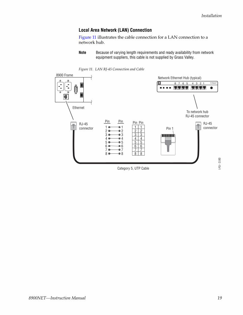
Local Area Network (LAN) ConnectionFigure 11 illustrates the cable connection for a LAN connection to a network hub.
Note Because of varying length requirements and ready availability from network equipment suppliers, this cable is not supplied by Grass Valley.
Figure 11. LAN RJ-45 Connection and Cable
8900 Frame
RJ-45connector
RJ-45connector
Pin Pin PinPin12345678
12345678
12345678
12345678
To network hubRJ-45 connector
Ethernet
Pin 1
Network Ethernet Hub (typical)
0612 -15r1Category 5, UTP Cable
8 7 10 BaseT6 5 4 3 2 1hp
8900NET—Instruction Manual 19

Power Up
Power UpThe various front LED indicators and configuration switches on the 8900NET module are illustrated in Figure 12. Upon power-up, all LEDs should light for the duration of the initialization process. The frame is powered up when either of the AC mains connections are made on the rear of the frame (Figure 6 on page 14 for Gecko frame and Figure 7 on page 14 for GeckoFlex frame).
After initialization the Power LED will be on and the red Network Module LED (labeled NM) should be off. All other LEDs report detected fault con-ditions within the frame and the installed modules. If the NM LED does not go off, the board needs servicing.
Note When a media module is first plugged into an 8900 frame, the 8900NET module may report a momentary fault. This will clear once the media module has booted up.
Figure 12. LEDs and Configuration Switches on the 8900NET Module
LEDs on the 8900NET module primarily indicate status items from the frame and the modules in the frame. Some functions specific to the 8900NET module are also reported (PWR, ETHER, COMM). LED reporting for each specific LED on the front of the 8900NET module can be disabled if desired on the LED Reporting web page (LED Reporting Web Page on page 48).
Table 2 on page 21 describes all the module’s LEDs and the conditions indi-cated.
FAN (red)
MOD - Module Health Bus (red)
PS1 - Power Supply 1 (red)
PS2 - Power Supply 2 (red)
TEMP - Temperature (red)
S1
87
65
43
21
87
65
43
21
PWR - Power (green)
Red = FaultGreen = OKYellow = Active
LED Color Key
NM - Network Interface Module (red)
FB - Frame Bus (red)
COMM - Communication (yellow)
ETHER - Ethernet communiction(yellow)
REM OVR - Remote Override (yellow)
FAULT - Frame Fault (red)
INHIB - Module Health Inhibited (yellow)
Configuration DIP switch S1
0612 -06r1
Configuration DIP switch S2
20 8900NET—Instruction Manual
Power Up
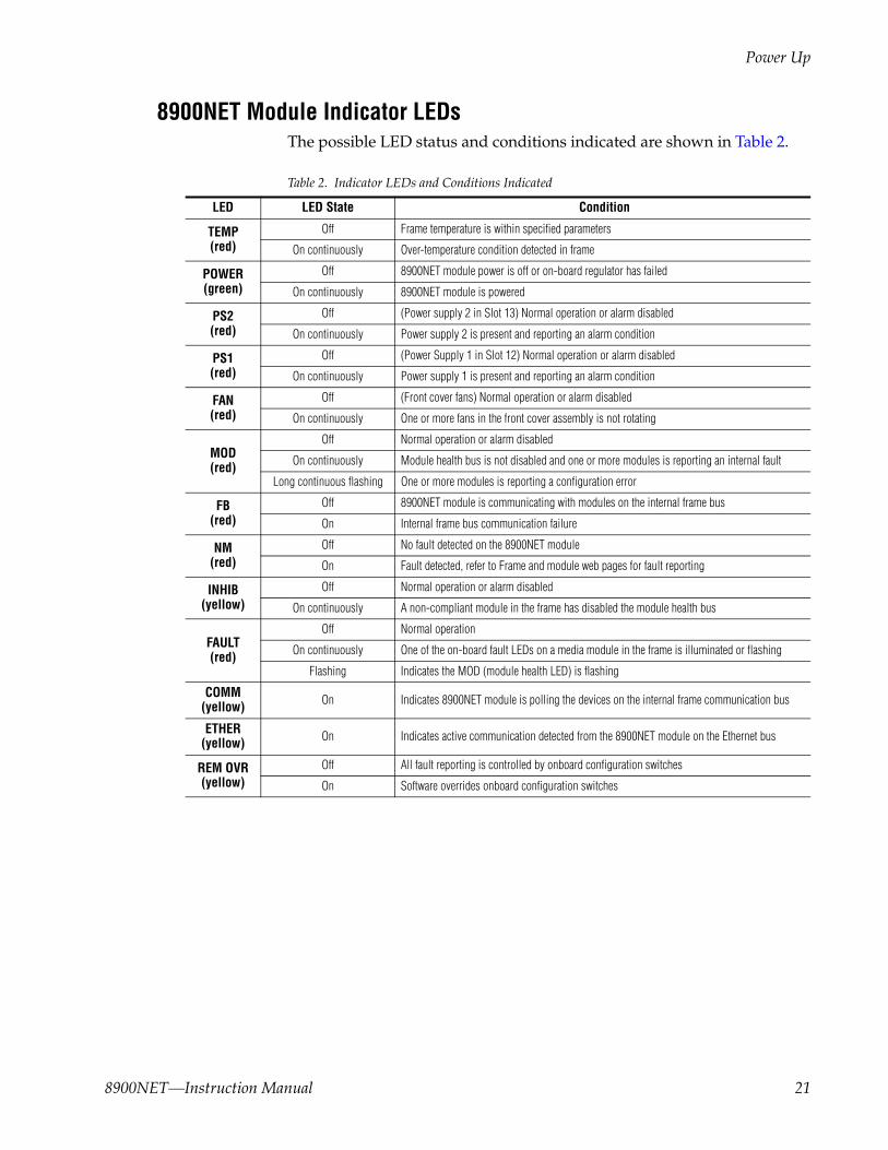
8900NET Module Indicator LEDsThe possible LED status and conditions indicated are shown in Table 2.
Table 2. Indicator LEDs and Conditions Indicated
LED LED State Condition
TEMP(red)
Off Frame temperature is within specified parameters
On continuously Over-temperature condition detected in frame
POWER(green)
Off 8900NET module power is off or on-board regulator has failed
On continuously 8900NET module is powered
PS2 (red)
Off (Power supply 2 in Slot 13) Normal operation or alarm disabled
On continuously Power supply 2 is present and reporting an alarm condition
PS1 (red)
Off (Power Supply 1 in Slot 12) Normal operation or alarm disabled
On continuously Power supply 1 is present and reporting an alarm condition
FAN(red)
Off (Front cover fans) Normal operation or alarm disabled
On continuously One or more fans in the front cover assembly is not rotating
MOD(red)
Off Normal operation or alarm disabled
On continuously Module health bus is not disabled and one or more modules is reporting an internal fault
Long continuous flashing One or more modules is reporting a configuration error
FB(red)
Off 8900NET module is communicating with modules on the internal frame bus
On Internal frame bus communication failure
NM(red)
Off No fault detected on the 8900NET module
On Fault detected, refer to Frame and module web pages for fault reporting
INHIB(yellow)
Off Normal operation or alarm disabled
On continuously A non-compliant module in the frame has disabled the module health bus
FAULT (red)
Off Normal operation
On continuously One of the on-board fault LEDs on a media module in the frame is illuminated or flashing
Flashing Indicates the MOD (module health LED) is flashing
COMM(yellow) On Indicates 8900NET module is polling the devices on the internal frame communication bus
ETHER(yellow) On Indicates active communication detected from the 8900NET module on the Ethernet bus
REM OVR(yellow)
Off All fault reporting is controlled by onboard configuration switches
On Software overrides onboard configuration switches
8900NET—Instruction Manual 21
Establishing Frame Network Identity
Establishing Frame Network IdentityThe initial configuration of the 8900NET module, using the RS-232 port (refer to Figure 8 on page 16), establishes the frame’s network identity to enable the operation of the Web-based GUI. A PC running a terminal emu-lation application is used to set the initial parameters for network commu-nication. Once initial identity is established, the GUI can be used to make subsequent changes to the networking parameters. Parameters established include:
• Local IP Address,
• Gateway IP Address,
• Subnet Mask, and
• Default Route.
Note If the Gecko frame is to be connected point-to-point to a single PC worksta-tion, both the frame and the PC must be on the same Subnet.
NetConfig ApplicationWith software release 3.2.0 and later, 8900 frames can interface with Net-Config (Network Configuration Application). NetConfig is a PC software tool for configuring and setting up NetConfig-enabled Grass Valley devices. Refer to the NetConfig Manual or the 8900NET Release Notes for current information on using this tool.
Good Networking PracticesThe Local IP Address form of a URL can be used within an intranet to address the Gecko frame’s web page. An intranet is set up and maintained within your facility and is isolated from the Internet.
Access from outside, through the Internet, may require the use of a Domain Name and a firewall, depending upon your network architecture. Domain Name Addressing requires a Domain Name Server located within the intranet that maps the Domain Name to the frame’s IP Address. The Gecko frame has no knowledge of its assigned Domain Name. Network traffic through a Domain Name Server can delay 8900NET response time.
Remote workstations are also subject to network traffic delays. Local PC workstations should be used for real-time operation of the 8900NET.
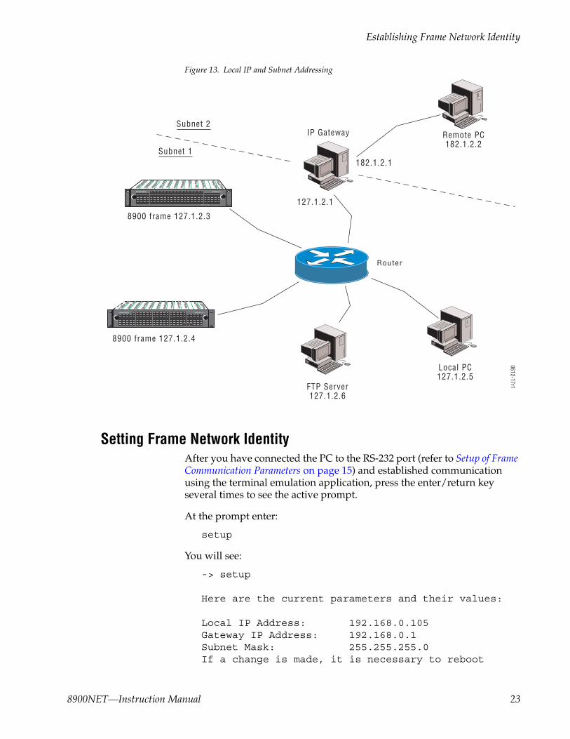
The most direct and timely access to the frame is achieved by using a PC workstation that is assigned to the same Subnet (see Figure 13 on page 23). A workstation in a different Subnet, even when located on the same router, will be subject to processing of the IP Gateway.
22 8900NET—Instruction Manual
Establishing Frame Network Identity
Figure 13. Local IP and Subnet Addressing
Setting Frame Network IdentityAfter you have connected the PC to the RS-232 port (refer to Setup of Frame Communication Parameters on page 15) and established communication using the terminal emulation application, press the enter/return key several times to see the active prompt.
At the prompt enter:
setup
You will see:
-> setup
Here are the current parameters and their values:
Local IP Address: 192.168.0.105Gateway IP Address: 192.168.0.1Subnet Mask: 255.255.255.0If a change is made, it is necessary to reboot
0612-17r1
Remote PC182.1.2.2
IP GatewaySubnet 2
182.1.2.1
127.1.2.1
Local PC127.1.2.5
Router
8900 frame 127.1.2.3
8900 frame 127.1.2.4
FTP Server127.1.2.6
PS 1 PS 2
LOCKLOCK
FAULT
PS 1 PS 2
LOCKLOCK
FAULT
Subnet 1
8900NET—Instruction Manual 23
Establishing Frame Network Identity
this machine. This will occur automatically whenyou have completed making changes.
Do you wish to change any of the values? y/n (n): y
For each parameter, you will be given the name of the parameter and its current value in parenthesis. To change it, just type in the new value. If you don't wish to change it, just hit the Enter key.
If you make a mistake on a previous value, continue with the remaining parameters; you will be given an opportunity to modify the value again.
Please ensure that you change from Factory defaults to your network parameters.
The local Ip Address is the Internet address of this machine. It consists of four numbers separated by pe-riods ('.'). Each number can be in the range of 0 to 255. For example: 192.168.0.105There must an IP address.
IP Address (192.168.0.105):
The Default Route is the Internet address of the ma-chine which routes network packets outside of the lo-cal network. It consists of four numbers separated by periods ('.').
Each number can be in the range of 0 to 255.For example: 192.168.0.1If you respond with a single period (.),a default route will not be assigned.
Default Route (192.168.0.1):
The Subnet Mask is used in the routing algorithm.The Net Card will use the mask to determine if a ad-dress is in local net or to send the message to the default. It consists of four numbers separated by pe-riods ('.').
Each number can be in the range of 0 to 255.For example: 255.255.255.0
If you respond with a single period (.),a Subnet Mask will not be assigned.Subnet Mask (255.255.255.0):
24 8900NET—Instruction Manual

Web Browser Setup
Network Configuration Storage8900NET software version 3.2.0 and later enables storage of the IP addresses (network configuration) on the frame backplane on frames that are equipped with storage capability (see Figure 6 on page 14). In earlier versions of software and frame types with no storage capacity, the IP addresses are stored on the 8900NET module and stay with the module when it is moved to another frame.
There are a number of ways to determine what type of frame you have. Table 3 lists all available frame types and how they can be identified. The assembly number of the frame is identified on a label located inside the frame inside the chassis.
To determine what frame model you have and where IP addresses are stored, you may also access the Frame Status page with the web browser (see Figure 31 on page 56). All frames with 8900NET cards with software version 3.2.0 and later will report a Network Config status message as one of the following:
• Network configuration stored on 8900NET module, or
• Network configuration stored on frame.
Web Browser Setup The recommended Windows operating systems currently supported for the web browser interface are Windows 2000 and XP. The web browser for use with the 8900NET Control and Monitoring System is either:
• Netscape Navigator 6.x or later, or
• Internet Explorer 6.x or later.
Versions 5.x or earlier of these browsers may cause undesirable results in the presentation of HTML frames.
Table 3. Gecko 8900 Frames Types IP Storage Capability
Model Number Backplane Assembly Number Network Config Storage
8900TFN-A Audio backplane with 1 IC 610-0960-00 8900NET module
8900TFN-V Video backplane with 1 IC 630-0063-00 8900NET module
8900TFN-A Audio backplane with 2 ICs 610-0960-01 Frame backplane
8900TFN-V Video backplane with 2 ICs 610-0984-00 Frame backplane
8900FFN Frame AC Rear with 2 ICs – Frame backplane
8900NET—Instruction Manual 25
Web Browser Setup
Web Browser Notes• If applicable, configure the browser for direct HTTP requests to the
frame rather than addressing a Proxy Web Server. The Modular Frame Web Server will typically be installed inside the firewall.
• For older Netscape browsers, the Cache should be configured to always refresh.
Addressing the Frame URL To address an 8900 frame from an internet browser, enter the frame’s default URL into the URL line of the browser (“Location” in Netscape Nav-igator, “Address” in Internet Explorer). The URL will be the IP Address given to the frame during initial setup (see Setting Frame Network Identity on page 23), or a Domain name that has been mapped to the IP Address in your Domain Name Server tables. The URL should look like this:
http://{Frame’s IP Address}/
Example:
http://127.123.234.2/
Or:
http://{Frame’s Domain Name}/
Example:
http://frame1.xyz.com/
The correctly entered URL will call up the Gecko frame’s default first page—Frame Status.
Default MAC (machine) AddressEach 8900 frame has a unique ethernet physical level MAC address that is stored in the frame ID memory chip (see Figure 6 on page 14). If this memory is missing, the 8900NET module will substitute a default MAC address: 08-00-11-09-CD-AB. If more than one 8900 frame in your network is assigned the default MAC address, network conflicts will occur. To verify the frame has a unique MAC address refer to 8900NET Network Web Page on page 61.
26 8900NET—Instruction Manual

Status Monitoring and Reporting
Status Monitoring and ReportingThis section provides a complete summary of frame and module status monitoring and reporting in a Gecko or GeckoFlex system with an 8900NET module installed in the frame. It summarizes what status items are reported and how to enable/disable reporting of each item.
There are a number of ways to monitor status of frame power supplies, fans, modules in the frame, and other status items depending on the method of monitoring being used including a voltage level on the external Frame Alarm, module front edge LEDs, web browser indicators, and SNMP reporting.
Status reporting methods include the following:
• Module Health Bus and other frame status alarm reporting to external Frame Alarm output on the rear of the 8900 frame,
• LEDs on the Frame, 8900NET module, and individual frame media modules,
• Web browser status reporting for each frame component, and
• SNMP traps, captured by Thomson Grass Valley’s NetCentral or another SNMP Manager Application.
Note SNMP trap information is only available when an SNMP Agent has been installed and configured.
8900NET—Instruction Manual 27
Status Monitoring and Reporting
External Frame AlarmThe Frame Alarm outputs a voltage level indicating there is an alarm con-dition on the Module Health Bus or one of the other frame components reported to the Frame Monitor module in a Gecko 8900TF or GeckoFlex 8900FF frame or the 8900NET module in an 8900TFN and GeckoFlex 8900FFN frame. The type of pulse on the external Frame Alarm can be set for Continuous or Pulsing on the Frame Alarm Reporting web page (Frame Alarm Reporting Web Page on page 42). Refer also to Frame Alarm on page 15 for more details on using this connector.
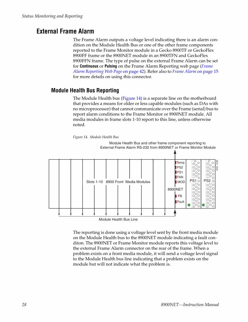
Module Health Bus ReportingThe Module Health bus (Figure 14) is a separate line on the motherboard that provides a means for older or less capable modules (such as DAs with no microprocessor) that cannot communicate over the Frame (serial) bus to report alarm conditions to the Frame Monitor or 8900NET module. All media modules in frame slots 1-10 report to this line, unless otherwise noted.
Figure 14. Module Health Bus
The reporting is done using a voltage level sent by the front media module on the Module Health bus to the 8900NET module indicating a fault con-diton. The 8900NET or Frame Monitor module reports this voltage level to the external Frame Alarm connector on the rear of the frame. When a problem exists on a front media module, it will send a voltage level signal to the Module Health bus line indicating that a problem exists on the module but will not indicate what the problem is.
0612_33r0
Module Health Bus Line
Module Health Bus and other frame component reporting to External Frame Alarm RS-232 from 8900NET or Frame Monitor Module
Slots 1-10 8900 Front Media Modules PS1 PS2
Temp
PS2
PS1
FAN
FB
Fault
MOD
8900NET
28 8900NET—Instruction Manual
Status Monitoring and Reporting
Module Health Bus status will report the following items on a media module:
• Internal module state (and state of submodule or options enabled) including configuration errors (warning), internal faults, and normal operation (Pass).
• Signal input states including valid/present (pass), not present or invalid (warning), not monitored, and not available (no signal inputs).
• Reference input states including locked/valid (pass), not locked/invalid (warning), and not monitored.
• Signal output states with reporting functionality (reference output).
The Module Health Bus status is also reflected on the 8900NET module. When one of the above conditions exists on a media module, the MOD LED on the front of the 8900NET module (Figure 12 on page 20 and Figure 14 on page 28) will light indicating that there is an error condition on the Module Health bus.
The Module Health bus status is also reported on the Frame Status web page as a Fault (when 3 or more modules are reporting an error condition) and on the Frame Alarm Reporting web page. This status reporting can be enabled or disabled using the Internal Healthbus control on the Frame Alarm Reporting web page (Frame Alarm Reporting Web Page on page 42). Dis-abling this reporting does not disable the actual Module Health Bus reporting to the Frame Alarm, only status reporting.
The Module Health Bus may be completely disabled by:
• Setting DIP switch S1, segment 5 to Disabled (Table 1 on page 12), or
• Unchecking the Module Health Reporting selection on the Frame Reporting web page (page 42) or the LED Reporting web page (page 48).
8900NET—Instruction Manual 29

Status Monitoring and Reporting
LED Status ReportingLEDs on the 8900NET module, media modules in the frame, and on the front cover of the Gecko (8900TF/TFN-V/-A) and GeckoFlex (8900FF/FFN) frames indicate fault status of the frame and the installed power supplies, fans in the front covers, and front media modules.
When the red FAULT LED is lit on an 8900NET module the fault will also be reported on the frame front cover. The LEDs on the front of the 8900NET module can then be read to determine the following frame and module fault conditions:
• Power Supply 1 and 2 health,
• Fan rotation status,
• Frame over-temperature condition,
• Frame Bus fault (8900NET only), and
• Module health bus status.
In general, LED colors used on the frame and modules indicate:
• Green – normal operation, (Pass) or signal present, module locked.
• Red – On continuously = fault condition, flashing = configuration error.
• Yellow – On continuously = active condition (configuration mode or communication), flashing in sequence = module locator function.
Status LEDs for the 8900NET module are shown in Figure 12 on page 20 and described in Table 2 on page 21. LEDs for the Frame Monitor module that comes in the 8900TF-V/TF-A or 8900FF frames are described in the Gecko 8900 Frames Instruction Manual or the GeckoFlex Frames Instruction Manual.
Status reporting to the LEDs on the front of the 8900NET card can be dis-abled if desired on the LED Reporting web page. Refer to the LED Reporting Web Page on page 48 for complete details.
30 8900NET—Instruction Manual

Status Monitoring and Reporting
Web Browser Status ReportingWhen the 8900NET module is installed in the frame, a web browser GUI can indicate frame and module status on the following web pages:
• Frame Status web page – reports overall frame and module status in graphical and text formats. Refer to Frame Status Page on page 34 for complete details.
• Module Status web page – shows specific input and reference signal status to the module along with enabled options and module versions.
• A Status LED icon is present on each web page to report communica-tion status for the frame slot and acts as a link to the Status web page where warnings and faults are displayed (8900NET version 3.0 or later).
In general, web page graphics and text colors used indicate the following:
• Green = Pass – signal or reference present, no problems detected.
• Red = Fault – fault condition.
• Yellow = Warning – signal is absent, has errors, or is mis-configured.
• Gray = Not monitored (older 8900 module).
• White = Not present.
Status reporting for the frame is enabled or disabled with the 8900NET module configuration DIP switches (see 8900NET Module Alarm DIP Switches on page 11). Some module status reporting items can also be enabled or disabled on individual configuration web pages.
8900NET—Instruction Manual 31

Status Monitoring and Reporting
SNMP MonitoringThe Thomson Grass Valley Modular Control and Monitoring System uses the Simple Network Monitoring Protocol (SNMP) internet standard for reporting status information to remote monitoring stations. The SNMP reporting from the 8900NET module provides status reports (traps) for various frame and module faults and warnings as described in Table 4 on page 33.
Status reports (traps) are unsolicited reports sent from the SMMP Agent to one or more SNMP Managers such as Thomson Grass Valley’s NetCentral. Once an SNMP agent has been installed, the Gecko frame and each module slot can be configured to enable or disable these reports through the Frame SNMP Reporting web page (see LED Reporting Web Page on page 48).
Note Two of the DIP switches described in Table 2 on page 21 must be enabled for corresponding SNMP reporting of the system components (S1 segment 5 and S2 segment 1).
SNMP Trap severity can be one of three degrees:
• Warning – a limitation in the module’s intended performance,
• Alarm – a failure in communication with the module, or
• Informational – a configuration change such as a switch setting.
The enabled SNMP traps will be reported to any SNMP manager that is identified as an SNMP Report Destination in 8900NET configuration (see 8900NET Module Configuration Web Page on page 57. Trap severity is read-only hard-coded information that is interpreted and responded to by the SNMP Manager software configuration.
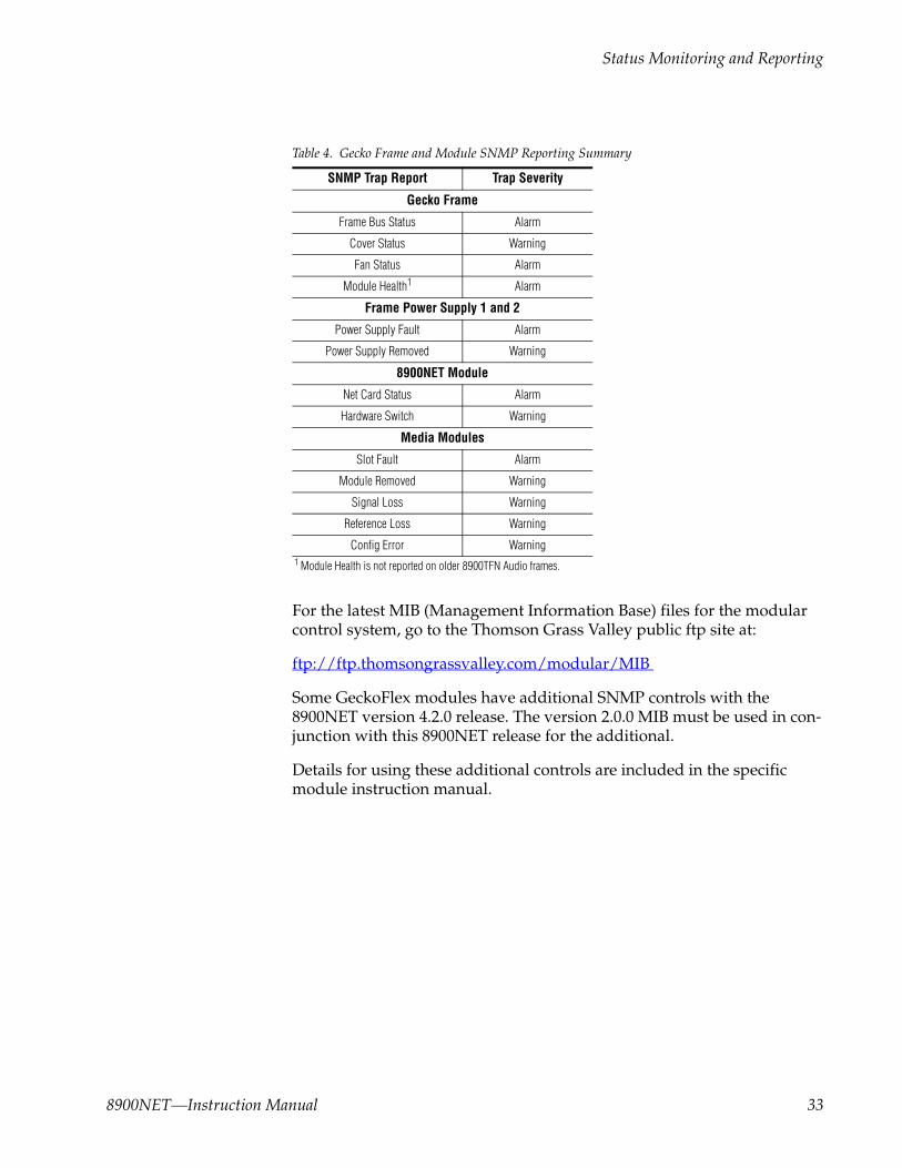
The SNMP traps available on the Gecko frames and modules are outlined in Table 4 on page 33. The SNMP trap reports available and their severity are configured on the Gecko Frame SNMP Reporting web page for all media modules, the 8900NET module, Power Supply 1 and 2, the Frame Bus Status, and Module Health status (8900TFN Video and GeckoFlex frames only).
32 8900NET—Instruction Manual
Status Monitoring and Reporting
For the latest MIB (Management Information Base) files for the modular control system, go to the Thomson Grass Valley public ftp site at:
ftp://ftp.thomsongrassvalley.com/modular/MIB
Some GeckoFlex modules have additional SNMP controls with the 8900NET version 4.2.0 release. The version 2.0.0 MIB must be used in con-junction with this 8900NET release for the additional.
Details for using these additional controls are included in the specific module instruction manual.
Table 4. Gecko Frame and Module SNMP Reporting Summary
SNMP Trap Report Trap Severity
Gecko Frame
Frame Bus Status Alarm
Cover Status Warning
Fan Status Alarm
Module Health1
1 Module Health is not reported on older 8900TFN Audio frames.
Alarm
Frame Power Supply 1 and 2
Power Supply Fault Alarm
Power Supply Removed Warning
8900NET Module
Net Card Status Alarm
Hardware Switch Warning
Media Modules
Slot Fault Alarm
Module Removed Warning
Signal Loss Warning
Reference Loss Warning
Config Error Warning
8900NET—Instruction Manual 33

Using the 8900NET GUI
Using the 8900NET GUIOnce the frame’s first web page—Frame Status—has been accessed (see Figure 15 on page 36), navigation can be done using the hypertext Link List in the left column. The Link List is a two-tier list with the frame’s devices at the highest tier and sub-pages for each device in a secondary tier (sub-list) below the parent device.
To navigate from device to device, click on a device link. This will open the device’s Status web page and open the sub-list of device web pages. You can also click on the slot icon in the content display to access a particular module’s Status web page.
To navigate to one of the device’s web pages click on any of the device’s sub-list of links. This will update the content display to the right.
Note To update status, web pages must be manually refreshed by clicking on the Refresh button (to the right of the page title and shown at left). Changes made at the frame or from other browsers or when a module has been removed and reinstalled, will not be displayed until the page is refreshed.
8900 Frame GUI InterfaceThis section describes the web browser interface for the Gecko and GeckoFlex frames.
Frame Status PageThe Frame Status web page (Figure 15 on page 36) displays an overall status for the frame.
The top section reports the following for the frame:
• Model Number,
• Description,
• Frame Location (defined in Frame Configuration),
• Temperature Status (PASS, ??, ??),
• Frame Health Alarm status (PASS, WARN, ALARM),
• Front Cover status (Cover installed, No Cover)
• Power Status indicates the power demand status (PASS, and
• Fan Status (On, ??, ??)
34 8900NET—Instruction Manual

Using the 8900NET GUI
The graphical content frame display shows:
• Module slot status and media module status,
• Power supplies installed (and empty slots),
• Presence of the 8900NET module (Net Card), and
• A clickable link to each device’s status page.
Module Slot StatusModule Slot Status icons report one of the following (Table 5):
Table 5. Module Status Indicators
Icon Color
Module Status Icon Text Indication
White None Empty No module detected in slot.
Gray No Comm No Comm Slot contains a legacy module which was not designed to support Frame Bus communications with an 8900NET module.
Green Pass Module Slot contains a fully Frame Bus capable module.
Yellow Warning Module 8900NET has detected a warning condition in module due to lack of input sig-nal or incomplete support for remote monitoring and control. Ability of module to perform intended operation is limited.
Red Fault Module 8900NET has detected a fault condition in module. Fault may have been com-municated over the Frame Bus, or may indicate a failure of the module to respond over the Frame Bus.
8900NET—Instruction Manual 35

Using the 8900NET GUI
Figure 15. 8900NET GUI for Frame Control
During initial polling, modules that do not respond immediately may tran-sition to a WARNING, MODULE NOT RESPONDING status. In this case, this is a tem-porary status until a maximum number of sequential attempts fail and a Fault is reported.
Note The first release of 8960DEC module code causes a Fault condition because it never responds on the Frame Bus. There is no way for the 8900NET module to tell the difference between a fully functional early release of 8960DEC and a module whose Frame Bus Interface has failed.
Note Early releases of the 8960ENC, 8950DAC, 8950ADC, 8920DAC, 8920ADC, and the 8916 signal a warning condition due to limited capability over the Frame Bus. All of these, except the 8916, can be upgraded by the user with fully capable Frame Bus software.
0612-12r3
The Links section lists the frame and its current modules. The selected link's Status page is first displayed and the sub-list of links for the selection is opened. The sub-list allows you to select a particular information page for the selected device.
Content display section displays the information page for the selected frame or module (frame slot icons are alsoactive links).
Refresh button for manual refresh of page
36 8900NET—Instruction Manual

Using the 8900NET GUI
Frame Properties
The Properties section on the Frame Status page reports:
• Vendor name,
• Number of media module slots,
• Software version (installed on the 8900NET module),
• Network Config (whether the network configuration is stored on the 8900NET module or on the frame backplane, depending on frame model). Refer to Network Configuration Storage on page 25.
Older 8900 Module Support8900 and other module type (8500/8800) Grass Valley modules that can reside in 8900 frames are supported to different degrees by the 8900NET module. A compatibility matrix describing the hardware versions, software update methods required, and remote control features of the various modules supported by the 8900 frames and 8900NET module is located in the Compatibility Matrix on page 83.
Note When the 8900NET is first installed or when many modules are installed simultaneously, it may take some time for the 8900NET to poll, update status and build the HTML pages, especially if there are modules that do not respond as expected, such as legacy modules. During these periods the Frame Status Page may fall behind temporarily until the 8900NET board can catch up and present a true current status.
8900NET—Instruction Manual 37

Using the 8900NET GUI
Legacy Module SupportInstallation of 8500 and 8800 modules shipped prior to November 15, 1999 will cause interruption of the Gecko and GeckoFlex frame communication bus. Modules shipped after this date have pins removed in the rear con-nector to provide compatibility. Compatible modules can be identified by the absence of connector pins 10 and 50 (see Figure 16). Incompatible legacy modules can be returned to Grass Valley for upgrade to the new con-nector.
Note If an unmodified legacy module is installed in the frame, the frame commu-nication bus will be interrupted and all module icons in the frame status display will be red. This problem occurs with legacy modules only and does not occur with other 8900 Series modules.
Figure 16. Modified Legacy Module Connector
Pin 10 Pin 50
0612-18
Pin 2
Top of Module
Pin 50Removed
Typical
38 8900NET—Instruction Manual

Using the 8900NET GUI
Frame Configuration Web PageUse the Frame Configuration web page shown in Figure 17 on page 40 to do the following for the frame:
• Locate Frame – Select the Flash radio button in the Locate Frame function to flash the front cover FAULT Indicator LED on the 8900NET module on and off with a 50 ms duty cycle to help locate the 8900 frame.
Note This function can also be performed using the NetConfig application. For Net-Config, right click on the frame name in the menu tree on the left side of the NetConfig screen and select Identify Device.
• Save/Load Frame Configuration File – save a frame configuration to a file by clicking on the Save To button. A frame configuration is saved to a default file (FrameConfigData.mcm) and the name cannot currently be changed. Follow the file download instructions for saving the file. This file can be recalled on this or any other networked 8900 frame to create a duplicate configuration.
Use the Browse button to locate a saved frame configuration file or enter a path and file name into the display. Select the Load button to load the selected configuration to the frame.
• Frame Identification – enter any name, an index number (for SNMP reporting), and a location name to identify a frame. You may also use the factory default frame name or location by selecting either Default button.
• Frame Health Reports – A link is provided to the Frame Alarm Reporting web page for (see Frame Alarm Reporting Web Page on page 42).
• LED Reports – a link is provided to the LED Reporting web page for (see LED Reporting Web Page on page 48).
• Frame SNMP Trap Reports – a link is provided to the SNMP Reporting web page (see Frame SNMP Trap Reports – a link is provided to the SNMP Reporting web page (see ). on page 39).
Usethislink
8900NET—Instruction Manual 39

Using the 8900NET GUI
Figure 17. Gecko Frame Configuration Web Page
40 8900NET—Instruction Manual
Using the 8900NET GUI
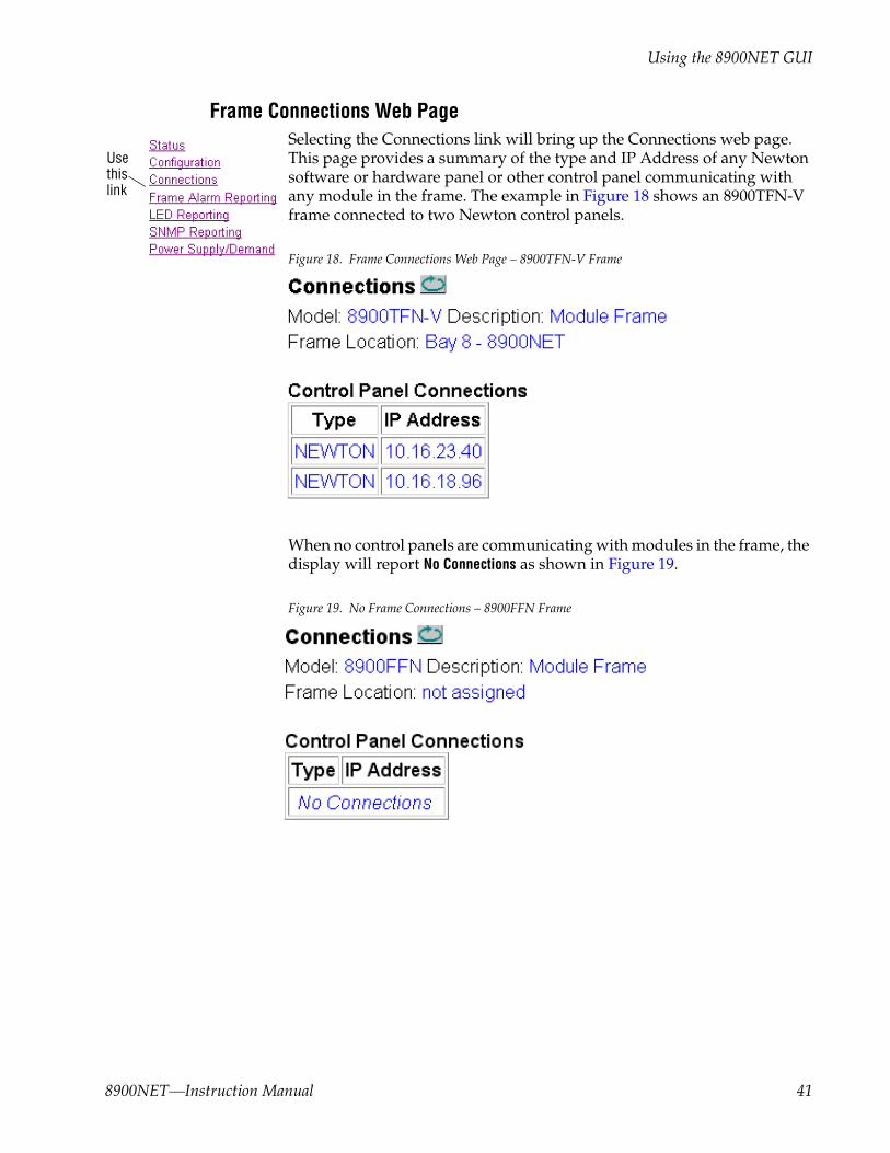
Frame Connections Web PageSelecting the Connections link will bring up the Connections web page. This page provides a summary of the type and IP Address of any Newton software or hardware panel or other control panel communicating with any module in the frame. The example in Figure 18 shows an 8900TFN-V frame connected to two Newton control panels.
Figure 18. Frame Connections Web Page – 8900TFN-V Frame
When no control panels are communicating with modules in the frame, the display will report No Connections as shown in Figure 19.
Figure 19. No Frame Connections – 8900FFN Frame
Usethislink
8900NET—Instruction Manual 41
Using the 8900NET GUI
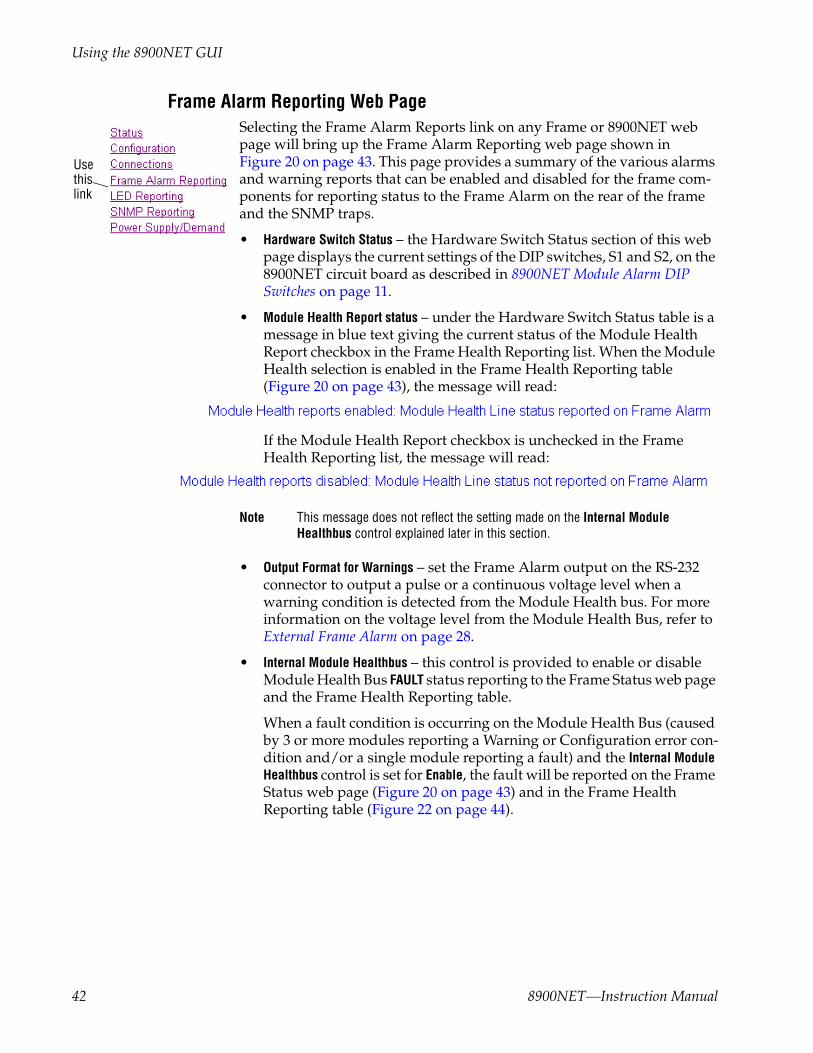
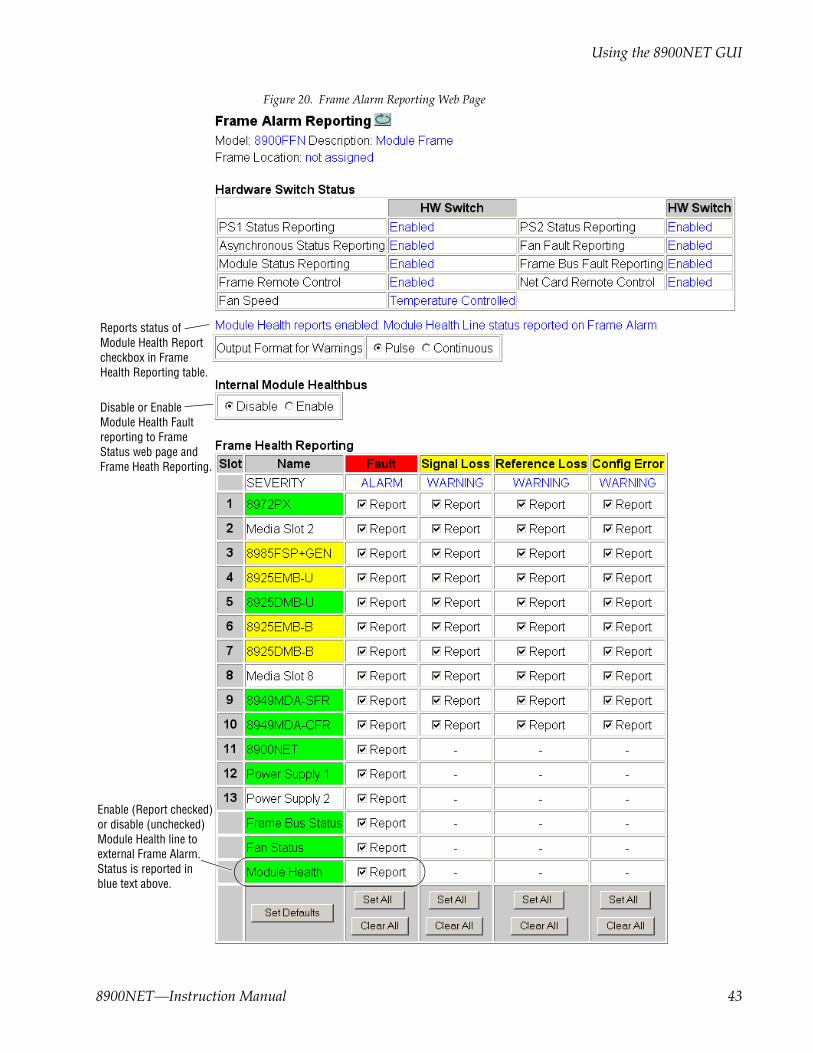
Frame Alarm Reporting Web PageSelecting the Frame Alarm Reports link on any Frame or 8900NET web page will bring up the Frame Alarm Reporting web page shown in Figure 20 on page 43. This page provides a summary of the various alarms and warning reports that can be enabled and disabled for the frame com-ponents for reporting status to the Frame Alarm on the rear of the frame and the SNMP traps.
• Hardware Switch Status – the Hardware Switch Status section of this web page displays the current settings of the DIP switches, S1 and S2, on the 8900NET circuit board as described in 8900NET Module Alarm DIP Switches on page 11.
• Module Health Report status – under the Hardware Switch Status table is a message in blue text giving the current status of the Module Health Report checkbox in the Frame Health Reporting list. When the Module Health selection is enabled in the Frame Health Reporting table (Figure 20 on page 43), the message will read:
If the Module Health Report checkbox is unchecked in the Frame Health Reporting list, the message will read:
Note This message does not reflect the setting made on the Internal Module Healthbus control explained later in this section.
• Output Format for Warnings – set the Frame Alarm output on the RS-232 connector to output a pulse or a continuous voltage level when a warning condition is detected from the Module Health bus. For more information on the voltage level from the Module Health Bus, refer to External Frame Alarm on page 28.
• Internal Module Healthbus – this control is provided to enable or disable Module Health Bus FAULT status reporting to the Frame Status web page and the Frame Health Reporting table.
When a fault condition is occurring on the Module Health Bus (caused by 3 or more modules reporting a Warning or Configuration error con-dition and/or a single module reporting a fault) and the Internal Module Healthbus control is set for Enable, the fault will be reported on the Frame Status web page (Figure 20 on page 43) and in the Frame Health Reporting table (Figure 22 on page 44).
Usethislink
42 8900NET—Instruction Manual
Using the 8900NET GUI
Figure 20. Frame Alarm Reporting Web Page
Reports status of
Enable (Report checked)or disable (unchecked)Module Health line toexternal Frame Alarm.
Module Health Reportcheckbox in FrameHealth Reporting table.
Status is reported in blue text above.
Disable or EnableModule Health Fault reporting to Frame Status web page and Frame Heath Reporting.
8900NET—Instruction Manual 43

Using the 8900NET GUI
Figure 21. Frame Status Web Page with Internal Module Healthbus Enabled
Figure 22. Frame Health Reporting Table with Internal Module Healthbus Enabled
44 8900NET—Instruction Manual
Using the 8900NET GUI
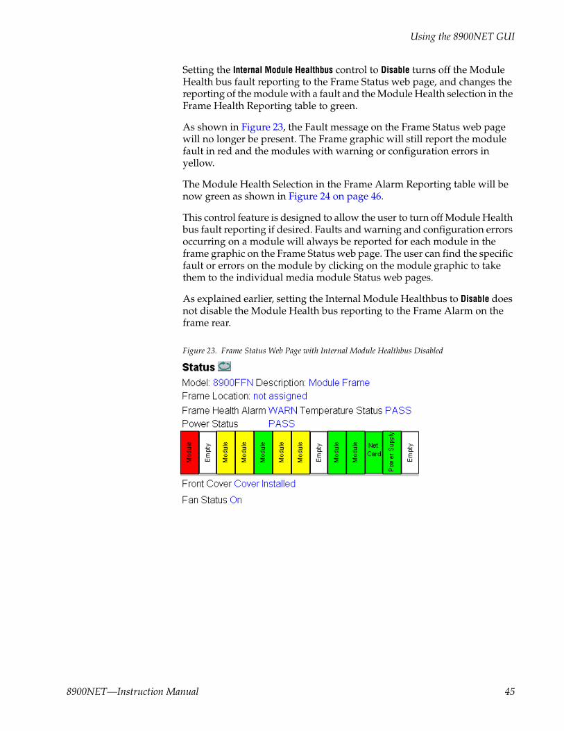
Setting the Internal Module Healthbus control to Disable turns off the Module Health bus fault reporting to the Frame Status web page, and changes the reporting of the module with a fault and the Module Health selection in the Frame Health Reporting table to green.
As shown in Figure 23, the Fault message on the Frame Status web page will no longer be present. The Frame graphic will still report the module fault in red and the modules with warning or configuration errors in yellow.
The Module Health Selection in the Frame Alarm Reporting table will be now green as shown in Figure 24 on page 46.
This control feature is designed to allow the user to turn off Module Health bus fault reporting if desired. Faults and warning and configuration errors occurring on a module will always be reported for each module in the frame graphic on the Frame Status web page. The user can find the specific fault or errors on the module by clicking on the module graphic to take them to the individual media module Status web pages.
As explained earlier, setting the Internal Module Healthbus to Disable does not disable the Module Health bus reporting to the Frame Alarm on the frame rear.
Figure 23. Frame Status Web Page with Internal Module Healthbus Disabled
8900NET—Instruction Manual 45

Using the 8900NET GUI
Figure 24. Frame Health Reporting Table with Internal Module Healthbus Disabled
Fault reporting (Red)has been disabled andset for Pass (green).
46 8900NET—Instruction Manual

Using the 8900NET GUI
• Frame Health Reporting – the Frame Health Reporting table (Figure 24 on page 46) listing each of the frame components is provided for enabling or disabling the report status of the following frame functions to the Frame Alarm on the rear of the frame and the SNMP traps:
• Media module (Slots 1-10) fault alarms, and loss of signal, loss of reference, and configuration error warnings (as specified for each specific module),
• 8900NET module fault reporting,
• Power supply 1 and 2 fault reporting,
• Frame Bus status fault reporting,
• Fan (in front cover) Status fault reporting, and
• Module Health bus reporting.
8900NET—Instruction Manual 47
Using the 8900NET GUI
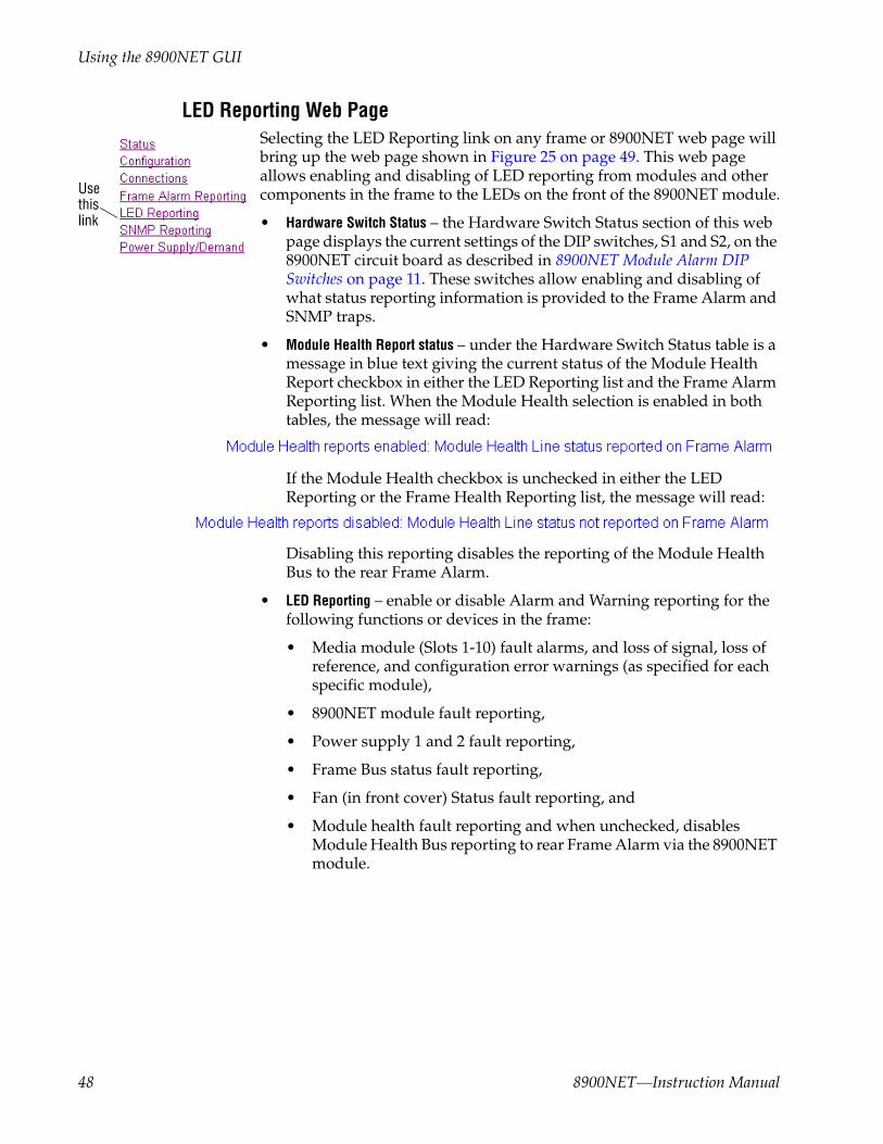
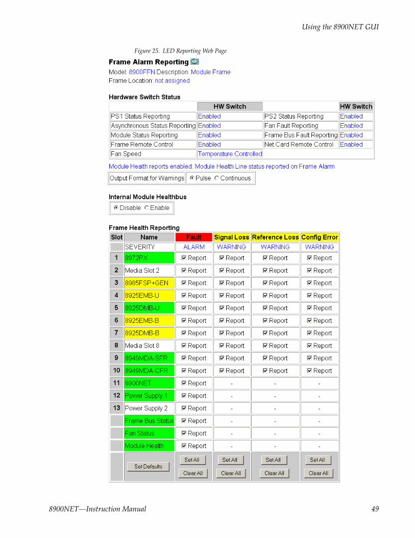
LED Reporting Web PageSelecting the LED Reporting link on any frame or 8900NET web page will bring up the web page shown in Figure 25 on page 49. This web page allows enabling and disabling of LED reporting from modules and other components in the frame to the LEDs on the front of the 8900NET module.
• Hardware Switch Status – the Hardware Switch Status section of this web page displays the current settings of the DIP switches, S1 and S2, on the 8900NET circuit board as described in 8900NET Module Alarm DIP Switches on page 11. These switches allow enabling and disabling of what status reporting information is provided to the Frame Alarm and SNMP traps.
• Module Health Report status – under the Hardware Switch Status table is a message in blue text giving the current status of the Module Health Report checkbox in either the LED Reporting list and the Frame Alarm Reporting list. When the Module Health selection is enabled in both tables, the message will read:
If the Module Health checkbox is unchecked in either the LED Reporting or the Frame Health Reporting list, the message will read:
Disabling this reporting disables the reporting of the Module Health Bus to the rear Frame Alarm.
• LED Reporting – enable or disable Alarm and Warning reporting for the following functions or devices in the frame:
• Media module (Slots 1-10) fault alarms, and loss of signal, loss of reference, and configuration error warnings (as specified for each specific module),
• 8900NET module fault reporting,
• Power supply 1 and 2 fault reporting,
• Frame Bus status fault reporting,
• Fan (in front cover) Status fault reporting, and
• Module health fault reporting and when unchecked, disables Module Health Bus reporting to rear Frame Alarm via the 8900NET module.
Usethislink
48 8900NET—Instruction Manual
Using the 8900NET GUI
Figure 25. LED Reporting Web Page
8900NET—Instruction Manual 49

Using the 8900NET GUI
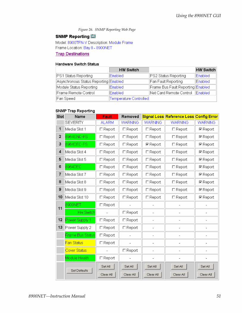
SNMP Reporting Web PageSelecting the SNMP Reporting web page link from any frame or 8900NET web page will bring up the web page shown in Figure 26 on page 51. When an SNMP Managers such as Thomson Grass Valley’s NetCentral is installed, SNMP trap reporting from the frame and modules can be config-ured using these controls.
• Trap Destinations – selecting the Trap Destinations link from this web page will bring up the 8900NET Configuration web page explained and shown in Figure 34 on page 60.
• Hardware Switch Status – the Hardware Switch Status section of this web page displays the current settings of the DIP switches, S1 and S2, on the 8900NET circuit board as described in 8900NET Module Alarm DIP Switches on page 11. These switches allow enabling and disabling of what status reporting information is provided to the Frame Alarm and SNMP traps.
• SNMP Trap Reporting – enable or disable SNMP Trap Alarm and Warning reporting for the following functions in the frame:
• Media module (Slots 1-10) fault alarms, and removed, loss of signal, loss of reference, and configuration error warnings (as specified for each specific module),
• 8900NET module fault reporting,
• Power supply 1 and 2 fault reporting,
• Frame Bus status fault reporting,
• Fan (in front cover) Status fault reporting, and
• Module health fault reporting.
Usethislink
50 8900NET—Instruction Manual
Using the 8900NET GUI
Figure 26. SNMP Reporting Web Page
8900NET—Instruction Manual 51

Using the 8900NET GUI
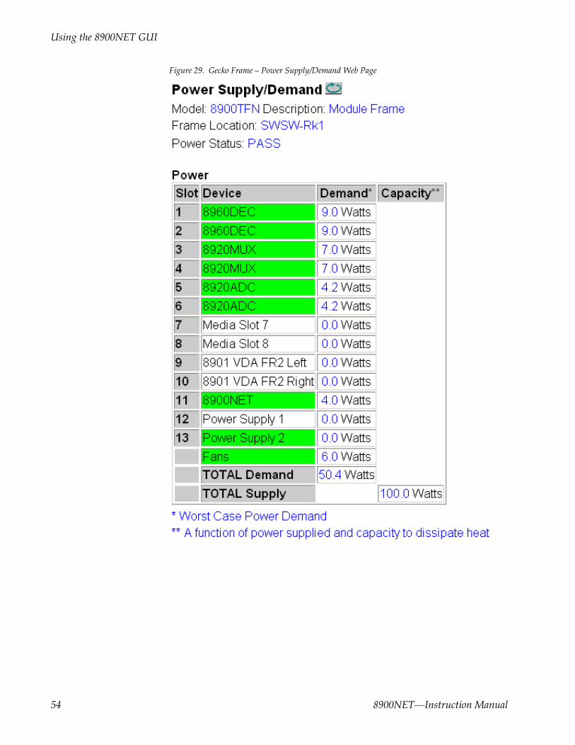
Power Supply/Demand Web PageThe Power Supply/Demand web page (Figure 28 on page 53 for GeckoFlex frame and Figure 29 on page 54 for Gecko frame) provides the following for the 8900 power supplies installed:
• Installed Power Supply – for GeckoFlex frames only, an Installed Power Supply setting is provided to identify to the frame what wattage power sup-plies are installed in the frame. The GeckoFlex frame currently ships with 125W power supplies and the Installed Power Supply setting is set for 125W at the factory.
Older GeckoFlex frames shipped with 100 Watt GeckoFlex power sup-plies installed. If you change a power supply from 125 Watt to 100 Watt, you will need to select the 100W setting to tell the frame what power supply is installed. This setting is not auto-sensing by the frame and must be set by the user. Using a 100W and a 125W supply in the same GeckoFlex frame will provide 100W of power for the frame.
CAUTION Do not swap power supplies between Gecko and GeckoFlex frames. Power supplies from a Gecko Frame are not swappable with the GeckoFlex frame power supply. Gecko power supplies are longer and do not fit in a GeckoFlex frame.
There are currently three types of power supplies available as listed below:
• Gecko Frame Power Supply (100W) – part number 119-6055-60 (used only in Gecko Frames)
• GeckoFlex Frame Power Supply (100W) – part number 711000120 (used in older GeckoFlex frames)
• GeckoFlex Frame Power Supply (125W) – part number 711017800 (used in currently shipping GeckoFlex frames)
To identify a power supply, note the part number on the large label on the side of the supply (Figure 27).
Figure 27. Power Supply Part Number Location
Usethislink
52 8900NET—Instruction Manual

Using the 8900NET GUI
• Power Status – gives the status of the power capacity for the frame. This is also reported on the Frame Status page.
• Power – a Power table lists each of the media modules, the 8900NET module, and the power supplies present in the frame and their power demand. The total amount of power demand is totaled at the bottom of the display.
Figure 28. GeckoFlex Frame – Power Supply/Demand Web Page
8900NET—Instruction Manual 53
Using the 8900NET GUI
Figure 29. Gecko Frame – Power Supply/Demand Web Page
54 8900NET—Instruction Manual
Using the 8900NET GUI
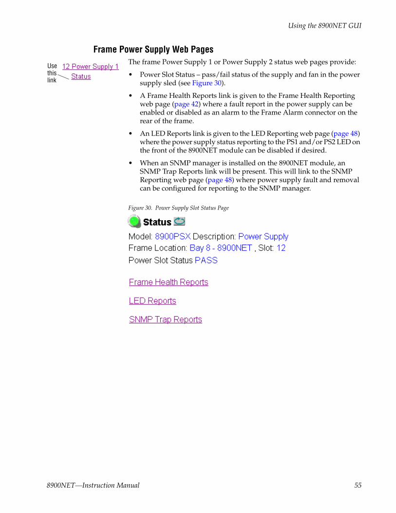
Frame Power Supply Web PagesThe frame Power Supply 1 or Power Supply 2 status web pages provide:
• Power Slot Status – pass/fail status of the supply and fan in the power supply sled (see Figure 30).
• A Frame Health Reports link is given to the Frame Health Reporting web page (page 42) where a fault report in the power supply can be enabled or disabled as an alarm to the Frame Alarm connector on the rear of the frame.
• An LED Reports link is given to the LED Reporting web page (page 48) where the power supply status reporting to the PS1 and/or PS2 LED on the front of the 8900NET module can be disabled if desired.
• When an SNMP manager is installed on the 8900NET module, an SNMP Trap Reports link will be present. This will link to the SNMP Reporting web page (page 48) where power supply fault and removal can be configured for reporting to the SNMP manager.
Figure 30. Power Supply Slot Status Page
Usethislink
8900NET—Instruction Manual 55

Using the 8900NET GUI
8900NET Module InterfaceThis section describes the web browser interface for the 8900NET module.
8900NET Module Status Web PageThe Status web page illustrated in Figure 31 displays 8900NET:
• Module identity, location and internal Net Card diagnostic Pass/Fail /Warning, status,
• Hardware and software properties,
• Asset Tag identifier (set on 8900NET Configuration web page), and
• Status of on-board hardware configuration switches (set as described in 8900NET Module Alarm DIP Switches on page 11).
A Status LED icon on each module page changes color to report status of network interface, frame bus, and internal diagnostics:
• Green indicates a Pass condition,
• Red indicates a Fail condition, and
• Yellow indicates a Warning condition.
Figure 31. 8900NET Module Network Status Page
Usethislink
56 8900NET—Instruction Manual

Using the 8900NET GUI
8900NET Module Configuration Web PageThe 8900NET Configuration web page (Figure 32) provides the following for configuring the 8900NET module:
• Reboot Module – reboot the 8900NET module by selecting the reboot button at the top of the page. A reboot can also be done on the Network web page.
• Install SNMP Agent – to use an SNMP Manager, an SNMP Agent software must be installed on the 8900NET module. The Configuration web page shown in Figure 32 is displayed if the agent software has not already been installed.
To install an SNMP Agent, refer to Install SNMP Agent on page 58. When the SNMP Agent has been installed, an SNMP Trap Reports link will be present on the Configuration web page (Figure 34 on page 60).
• Asset Tag Assignment – the 8900NET module can be assigned as asset tag identifier by entering numbers or text in the Asset Tag field. This infor-mation will appear on the 8900NET Status web page and in the module inventory when using the NetConfig Network Configuration applica-tion.
Figure 32. 8900NET Module Configuration Web Page (No SNMP Installed)
• Frame Health Reporting – a Frame Health Reports link to the Frame Alarm Reporting web page is provided. Refer to Frame Alarm Reporting Web Page on page 42.
• LED Reporting – an LED Reports link to the LED Reporting web page is provided. Refer to LED Reporting Web Page on page 48.
Usethislink
8900NET—Instruction Manual 57

Using the 8900NET GUI
Install SNMP AgentWhen SNMP Agent software is installed on the 8900NET module, enabled status reports are sent to an SNMP Manager such as the Grass Valley’s Net-Central application. Refer to Establishing Frame Network Identity on page 22 for more information.
To install an SNMP Agent, click on the Install SNMP Agent button (Figure 32 on page 57) to view the license agreement.
After reading the agreement, click on Accept to finish installing the SNMP Agent (Figure 33). Clicking the Decline button will abort the SNMP Agent installation and return you to the Configuration web page.
Figure 33. SNMP Agent Installation Agreement
58 8900NET—Instruction Manual

Using the 8900NET GUI
When the SNMP Agent is successfully installed, the Configuration web page will contain the additional items listed below and shown in Figure 34 on page 60.
• SNMP Trap Reports Link – when the SNMP Agent is installed an SNMP Trap Reports link will be present on the Configuration web page (and other web pages) to link to the SNMP Reporting web page (page 51).
The following SNMP trap reports are provided for the 8900NET module:
• Net Card Status (Alarm)
• Hardware Switch (Informational)
• SNMP Report Activation Modes – each report destination has an activation control that can select one of the following modes of operation:
• CREATE – GO creates a new report destination that becomes active after the next module reboot.
• CREATE – WAIT creates a new report destination that remains out of service until the user selects active and then reboots the module.
• ACTIVE changes a NOT IN SERVICE report destination to active after the next module reboot.
• NOT IN SERVICE changes an active report destination to inactive after the next module reboot.
• DELETE removes the report destination entry. If the entry was active it remains active until the next module reboot.
Note Report destination status does not change until the 8900NET module is rebooted.
The status column to the left of the activation operation pull-down window provides one of the following status reports:
• <BLANK> – No entry has been applied.
• ACTIVE – All new status reports will be sent to this destination.
• NOT IN SERVICE – The destination has a valid definition but the user has not activated it.
• ACTIVE PENDING REBOOT – This entry indicates the report destination will become active upon the next module reboot.
• NOT IN SERVICE PENDING REBOOT – This entry indicates the report des-tination will become inactive upon the next module reboot.
• NOT READY – The destination entry is invalid. The IP Address may not be properly defined or there is no IP Address or Community entry.
8900NET—Instruction Manual 59

Using the 8900NET GUI
Figure 34. 8900NET Configuration Web Page (SNMP Agent Installed)
60 8900NET—Instruction Manual

Using the 8900NET GUI
8900NET Network Web PageTo view or change the module identity and currently assigned network addresses for the 8900NET module access the Network web page illus-trated in Figure 35.
Note Depending on the type of frame this module is installed in, this network con-figuration is saved on either the 8900NET module or on the frame backplane. Refer to Network Configuration Storage on page 25 for details.
Figure 35. 8900NET Module Network Identification Page
After initial frame network addressing is done using the RS-232 port, sub-sequent address changes may be made using the web page shown above.
Note SubNet Mask and Gateway IP Address are required.
Rebooting the NET ModuleReboot the module for changes to take effect. You can reboot the 8900NET module from the Network page by clicking the reboot button. A reboot button can also be found on the Configuration page.
Usethislink
8900NET—Instruction Manual 61
Using the 8900NET GUI
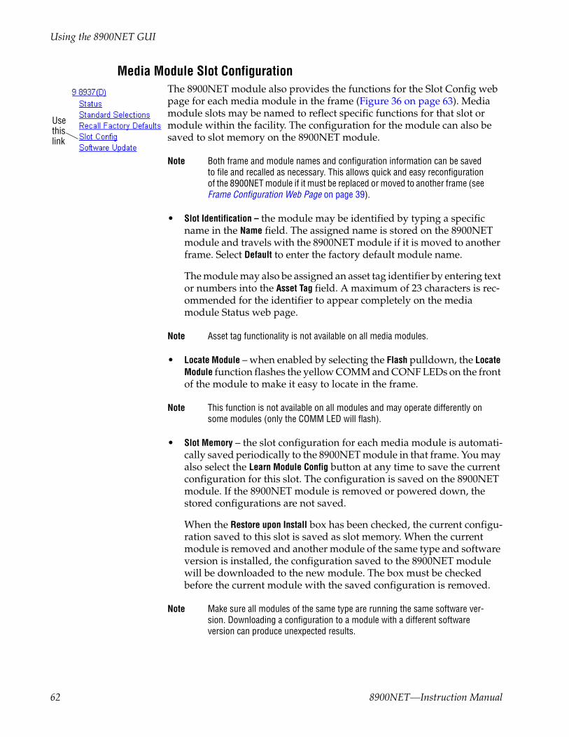
Media Module Slot ConfigurationThe 8900NET module also provides the functions for the Slot Config web page for each media module in the frame (Figure 36 on page 63). Media module slots may be named to reflect specific functions for that slot or module within the facility. The configuration for the module can also be saved to slot memory on the 8900NET module.
Note Both frame and module names and configuration information can be saved to file and recalled as necessary. This allows quick and easy reconfiguration of the 8900NET module if it must be replaced or moved to another frame (see Frame Configuration Web Page on page 39).
• Slot Identification – the module may be identified by typing a specific name in the Name field. The assigned name is stored on the 8900NET module and travels with the 8900NET module if it is moved to another frame. Select Default to enter the factory default module name.
The module may also be assigned an asset tag identifier by entering text or numbers into the Asset Tag field. A maximum of 23 characters is rec-ommended for the identifier to appear completely on the media module Status web page.
Note Asset tag functionality is not available on all media modules.
• Locate Module – when enabled by selecting the Flash pulldown, the Locate Module function flashes the yellow COMM and CONF LEDs on the front of the module to make it easy to locate in the frame.
Note This function is not available on all modules and may operate differently on some modules (only the COMM LED will flash).
• Slot Memory – the slot configuration for each media module is automati-cally saved periodically to the 8900NET module in that frame. You may also select the Learn Module Config button at any time to save the current configuration for this slot. The configuration is saved on the 8900NET module. If the 8900NET module is removed or powered down, the stored configurations are not saved.
When the Restore upon Install box has been checked, the current configu-ration saved to this slot is saved as slot memory. When the current module is removed and another module of the same type and software version is installed, the configuration saved to the 8900NET module will be downloaded to the new module. The box must be checked before the current module with the saved configuration is removed.
Note Make sure all modules of the same type are running the same software ver-sion. Downloading a configuration to a module with a different software version can produce unexpected results.
Usethislink
62 8900NET—Instruction Manual

Using the 8900NET GUI
If a different type of module is installed in this slot, a warning message will state that the original module type has been replaced with another module type. In this case, a Clear button will appear allowing you to clear the stored configuration from the previous module (see Figure 36).
• A Frame Health Reports link is provided to the Frame Alarm Reporting web page for setting up frame health reporting for this media module (see the Frame Alarm Reporting Web Page on page 42).
• An LED Reports link is provided to the LED Reporting web page for setting up LED reporting to the 8900NET module for this media module (see the LED Reporting Web Page on page 48).
• An SNMP Trap Reports link is provided to the SNMP Reporting web page for setting up SNMP Trap Reporting for this media module (see the SNMP Reporting Web Page on page 50).
Figure 36. Media Module Slot Configuration Page
8900NET—Instruction Manual 63

Using the 8900NET GUI
Upgrading 8900NET SoftwareSoftware updating procedures for 8900 Gecko and GeckoFlex products are provided in the release notes that accompany the specific software release. Refer to the latest 8900NET version release notes for full updating instruc-tions. These release notes are normally posted with the software update files and on the Modular documentation area of the Thomson Grass Valley web site at this URL:
http://www.thomsongrassvalley.com/docs/modular/
There are currently two ways of updating software on 8900NET modules as described below:
• 8900NET (version 3.2.0 and later) and some applicable 8900 modules should be updated using the NetConfig Networking Application, available free of charge from the Thomson Grass Valley ftp site:
ftp://ftp.thomsongrassvalley.com/router/NetConfig/Version 2.0.8/
• Older version (2.1.2 and earlier) 8900NET modules must be updated using the FTP download method described in 8900NET Software Update From FTP Server on page 87.
Acquiring Module Software UpdatesSoftware field upgrade packages for modules are available from the Thomson Grass Valley Customer Service FAQ site and the public ftp site.
You may connect to the Grass Valley FAQ site to access the latest module and free NetConfig software and subscribe to software updates automati-cally at the following URL:
http://www.thomsongrassvalley.com/downloads
This link will direct you to the Customer Service FAQ database where all software downloads are distributed. The information provided here is the most up-to-date. Using this link is recommended so that when new ver-sions of software are released, you are notified by E-mail. It also provides information on module software updating, including a list of the modules that do not support remote upgrades and require the cable kit.
To find the latest available 8900 software on the FAQ site, do the following:
1. Navigate to the FAQ site and click on the first FAQ in the list labeled DOWNLOAD THE LATEST SOFTWARE?
2. Select the 8900 Series link. There will be a list of all available 8900 software that can be upgraded remotely and below that, a list of the 8900 modules that require the 8900 upgrade kit.
Note Read the README file first if provided, before proceeding with a software download.
64 8900NET—Instruction Manual
Service
ServiceThe 8900NET modules make extensive use of surface-mount technology and programmed parts to achieve compact size and adherence to demanding technical specifications. Circuit modules should not be ser-viced in the field.
If your module is not operating correctly, proceed as follows:
• Check frame and module power and signal present LEDs.
• Check network connections at the frame and network routing devices.
• Verify that all ethernet devices have a unique MAC and IP Address/ Domain Name.
• Reboot the 8900NET module (see Rebooting the NET Module on page 61).
Refer to Figure 12 on page 20 for the location of PWR LED and Table 2 on page 21 for proper LED indications.
If the module is still not operating correctly, replace it with a known good spare and return the faulty module to a designated Grass Valley repair depot. Call your Grass Valley representative for depot location.
Refer to Contacting Grass Valley at the front of this document for the Grass Valley Customer Service Information number.
8900NET—Instruction Manual 65

Troubleshooting GUI Operation
Troubleshooting GUI OperationThe following is a list of possible 8900NET GUI and network problems and logical steps for troubleshooting them.
Cannot Open Any of the Frame’s Web Pages
1. Check power to the frame.
a. Is at least one of the power supplies operating?
b. Is the 8900NET module’s PWR LED on?
2. Check that the frame is physically connected to the network.
a. Is a cable plugged into the RJ45 connector of the frame?
b. Is that cable also connected to a 10Base-T Ethernet hub?
c. Does the 8900NET module’s ETHER LED indicate network activity?
d. Does the Ethernet hub have any indication that a link is established to the frame?
3. Is the correct IP Address/URL being used to address the frame?
If a Domain Name is being used to address the frame, try to connect using the frame IP Address instead.
The Domain Name may not be properly assigned in the local Domain Name Server or in the workstation’s host file.
The Domain Name Server may not be available to the workstation. Check that the 8900NET module has been properly configured.
a. Is the correct IP Address or URL being addressed in the web browser?
b. Was the 8900NET module configured over the serial connection with the SETUP command?
c. Has the 8900NET module been assigned the correct IP Address in SETUP (re-run setup over the serial connection)?
d. Is the workstation in the same subnet as the frame? If not:
Has the 8900NET module been assigned the correct Default Routing Address?
Has the 8900NET module been assigned the correct Subnet Mask?
e. Has the 8900NET module been rebooted since new IP Address, Default Routing, or Subnet Mask were assigned or changed?
4. Check if the frame web pages can be opened from a different workstation on the network.
66 8900NET—Instruction Manual
Troubleshooting GUI Operation
5. Is the subject workstation physically connected to the network?
6. Check that the workstation and browser have been properly configured.
a. Can the frame be opened from a different workstation?
b. Has the workstation been assigned a proper IP Address?
c. Has the workstation been assigned a Gateway Address?
d. Is the browser configured to connect to the correct port?
Is it attempting to connect through a modem when it should be con-necting through a network interface module?
Some laptop have two separate network ports, one for stand-alone operation, and the other for operation with a docking station. Is the correct port being used?
7. Check that network traffic can be routed between the workstation and the frame.
a. If the workstation supports a network ping, ping the frame. For example, using Windows NT:
Open a command prompt (DOS window)
In the DOS window, enter:
C:\> ping frame’s ip address
The results will indicate if the ping reached the frame.
b. If the workstation does not support a network ping, ping the workstation for the frame serial interface:
In the frame serial command window, enter:
->ping “workstation’s IP address”
The workstation’s IP address must be inside the double quotes. The results will indicate if the ping reached the workstation.
c. If the network ping failed, there may be a network problem between the frame and the workstation. To ensure it is not the frame, check the frame with a point-to-point connection:
Using a crossover Ethernet cable, connect the frame directly to a workstation. The workstation should be assigned an IP Address on the same Subnet as the frame. Attempt to load the frame’s web page from a Browser on this workstation.
8900NET—Instruction Manual 67
Troubleshooting GUI Operation
8. If the point-to-point connection attempt fails call Customer Service. If the point-to-point connection attempt succeeds, the problem is somewhere in the network between the original workstation and the frame.
a. Check the connectivity to the frame from different locations in the network to attempt to isolate physical disconnect problems.
b. Check the connectivity to the frame from inside and outside the frame’s subnet to isolate IP Gateway routing problems.
c. Check for possible Ethernet MAC Address collisions.
If the Frame ID Memory chip installed on the rear of the frame is missing or has failed, the frame adopts the default Ethernet MAC Address.
If more than one frame in the Network adopts the default Ethernet MAC Address, there could be address resolution problems. Upon power up the frame will indicate in the serial port console window, either:
“MAC address is unique!” – The Frame has successfully retrieved a unique Ethernet MAC Address from the Frame ID Memory chip
or
“MAC address is default!” - The Frame is using the default Ethernet MAC Address. The Frame ID Memory chip is missing or has failed. Call Grass valley Group Customer Service
Cannot modify parameters on Web Page
1. Check if parameters can be set for other modules.
If so, the module may be in a remote lockout state.
a. Check if the LOC/REM – LOCAL jumper on the module is set for local control only. (Refer to that specific module’s manual for help.)
b. In version 2.0 and later of the 8900NET module software, the web pages for a module in the remote lockout state will indicate that module remote control is disabled and the module’s controls on the web pages will be in read-only mode.
If other modules are not controllable, the entire frame may be in a remote lockout state. In this state, software updates to the modules and the 8900NET module are also locked out.
c. Check The 8900NET module’s status page if the frame remote control is disabled.
If so, flip Switch 3 on the S2 DIP switch block (FRAME CNTRL) to the enabled setting.
68 8900NET—Instruction Manual

Troubleshooting GUI Operation
2. If it is only a specific parameter that is read-only, the module may be in a mode assigning read-only operation to that parameter. Refer to the module’s instruction manual.
3. If only the 8900NET module is read-only, the 8900NET module may be in remote lockout mode.
a. Check the 8900NET module’s status page to see if the NET CARD REMOTE CONTROL status is disabled.
b. If so, flip Switch 8 on the S1 DIP switch block (NM CNTRL) to the enabled setting.
Cannot Connect to the Frame From a VTECS1 VideoFrame Control Panel
1. Check that the frame is powered and configured with a 8900NET module on the network.
2. Check that the 8900NET module in the frame is loaded with software version 2 or later.
Version 1 software does not support the control panel connection.
3. Check that the control panel has been properly configured with IP Address, Gateway IP Address, and Subnet Mask. (Refer to the control panel’s help feature or instruction manual.)
4. Check that the frame’s correct IP Address has been configured in the control panel’s frame address.
5. Check that the control panel is physically connected to the network.
a. Check that the control panel is connected to a port on an Ethernet hub.
b. Check if the L LED (L for link) on the back of the control panel is on.
If the LED indicates no link (off), try a different hub port connection.
If the LED still indicates no link, change the cable.
If the LED still indicates no link, contact VideoFrame.
6. Check that the frame is addressable by the control panel.
a. Check if the T LED (T for transmit) on the back of the control panel flashes upon the attempt to connect to the frame.
If T does not flash, contact VideoFrame.
b. Check if the R LED (R for receive) on the back of the control panel flashes upon the attempt to connect to the frame.
If R does not flash, there may be a problem in the network path between the frame and the control panel.
8900NET—Instruction Manual 69
Troubleshooting GUI Operation
7. Check that the frame is addressable on the network from a Web browser, refer to the steps on page 66.
a. Attempt to connect to a different frame.
If successful the problem may be with the original frame or the path between the control panel and the original frame.
b. Check from a workstation connected to the same Ethernet hub as the control panel. If unsuccessful, there may be a problem with the network path between the frame and this hub.
Event Messages From the Frame Are Not Being Displayed by NetCentral or Another SNMP Manager Application
1. Check that the frame is powered on and configured with an 8900NET module on the Network.
2. Check that the 8900NET module in the frame is loaded with software version 2.1 or later.
Earlier versions of software do not support SNMP.
3. Check that the SNMP Agent has been installed and configured on the 8900NET module.
View the 8900NET module CONFIGURATION page and note the event con-figuration parameters, the NET CARD EVENT REPORTS form and REPORT DESTINATIONS table.
If these are not visible, install the SNMP Agent per the instructions in the manual.
4. Check that the IP Address and Community Name for the SNMP Manager has been assigned in the REPORT DESTINATIONS table and is Active.
• If there is no entry for the SNMP Manager in the Table, the SNMP manager’s IP Address and Community name must be entered (see 8900NET Module Configuration Web Page on page 57).
• If the entry for the SNMP Manager is incorrect, it must be corrected, activated, and the 8900NET module must be rebooted.
• If the entry has been entered and the Status of the entry is reported NOT IN SERVICE, the Active operation for that entry must be selected, applied and the 8900NET module must be rebooted.
• If the entry has been entered and the Status of the entry is NOT READY, the entry must be corrected, activated and the 8900NET module must be rebooted.
• If the entry has been entered and the Status of the entry is ACTIVE –PENDING REBOOT, the 8900NET module must be rebooted.
70 8900NET—Instruction Manual

Troubleshooting GUI Operation
5. Check that the particular event has been enabled in the frame.
• For all events, check that the STATUS switch (Switch 1) on the S2 DIP switch block of the 8900NET module is Enabled.
• For Module Failure-Fixed events:
Check that the MODULE switch (Switch 5) on the S1 DIP switch block of the 8900NET module is Enabled, and
Check that the SLOT STATUS REPORTING parameter on the slot’s SLOT CONFIG page is Enabled.
• For Power Supply Failure-Fixed events:
Check that the PS1 or PS2 switch (Switch 1 or 2) on the S1 DIP switch block of the 8900NET module is Enabled, and
Check that the POWER SUPPLY STATUS REPORTING parameter on the power supply’s CONFIGURATION page is Enabled.
• For 8900NET module Failure-Fixed events, check that the NET CARD STATUS REPORTING parameter on the 8900NET module’s CONFIGURA-TION page is Enabled.
• For Hardware Switch change events, check that the HARDWARE SWITCH REPORTING parameter on the 8900NET module’s CONFIGURA-TION page is Enabled.
• For Frame Bus Failure-Fixed events:
Check that the FRAME BUS switch (Switch 6) on the S1 DIP switch block of the 8900NET module is Enabled, and
Check that the FRAME BUS STATUS REPORTING parameter on the frame’s CONFIGURATION page is Enabled.
• For Front Cover Removed -Installed events, check that the COVER STATUS REPORTING parameter on the frame’s CONFIGURATION page is Enabled.
• For Frame Bus Failure-Fixed events:
Check that the FRAME BUS switch (Switch 6) on the S1 DIP switch block of the 8900NET module is Enabled, and
Check that the FRAME BUS STATUS REPORTING parameter on the frame’s CONFIGURATION page is Enabled.
• For Cooling Fan Failure-Fixed events:
Check that the FAN switch (Switch 4) on the S1 DIP switch block of the 8900NET module is Enabled, and
Check that the FAN STATUS REPORTING parameter on the frame’s CON-FIGURATION page is Enabled.
• For Module Health Failure-Fixed events,
Check that the MODULE switch (Switch 5) on the S1 DIP switch
8900NET—Instruction Manual 71

Troubleshooting GUI Operation
block of the 8900NET module is Enabled, and
Check that the MODULE HEALTH REPORTING parameter on the frame’s CONFIGURATION page is Enabled.
• Check that the SNMP Manager is properly configured to receive the Event Messages.
Check that the SNMP Manager has been assigned the same commu-nity name as in the frame’s configuration.
6. Check the network connectivity between the SNMP Manager and the frame as described in the steps on page 66.
72 8900NET—Instruction Manual

Troubleshooting GUI Operation
LogPrint Procedure From Gecko/GeckoFlex FrameYou may use the logging function of the 8900NET module to troubleshoot errors from modules in the Gecko or GeckoFlex frame. The log will report the last 300 commands received by the Gecko frame. It will contain all com-mands from changes made through the web interface or control panel.
To access a LogPrint from an 8900 frame do the following:
1. Access HyperTerminal by pressing the Start button. Select Programs/Accessories/Communications/HyperTerminal as shown in Figure 37.
Figure 37. Find HyperTerminal
2. Click on the HyperTerminal accessory. HyperTerminal will open and bring up the Connection Description window shown in Figure 38 on page 74.
3. Type telnet into the Name field and select OK.
8900NET—Instruction Manual 73

Troubleshooting GUI Operation
Figure 38. Connection ‘Description Window
This will bring up the Connect To window shown in Figure 39.
4. In the Connect To window, select TCP/IP (Winsock) selection in the Connect Using pulldown.
Figure 39. Connect To Window
This will bring up the telnet window shown in Figure 40 on page 75.
5. In the Host address field that appears, type the IP address of the frame you wish to connect to and press OK.
74 8900NET—Instruction Manual

Troubleshooting GUI Operation
Figure 40. Enter Host Address
This will bring up the telnet-HyperTerminal screen shown in Figure 41.
Figure 41. Telnet Screen
6. To save the log to a .txt file while it is running, select the Transfer pulldown in HyperTerminal and select Capture Text before running the log (Figure 42 on page 76).
8900NET—Instruction Manual 75

Troubleshooting GUI Operation
Figure 42. Capture Text Pulldown
7. In the Capture Text window, browse to a location to save the text file as shown in Figure 43. Select the Start button. This will capture the text until you indicate it to stop.
Figure 43. Capture Text
8. On the HyperTerminal screen, Press the Enter key several times to verify the connection, then enter the LogPrint command shown in Figure 44.
Figure 44. LogPrint Prompt
9. Press the Enter key to run the log.
10. Once the log has stopped, you may also stop the text capture by selecting Capture Text in the Transfer pulldown again and select Stop (Figure 45).
The text file will now contain a record of the last 300 commands received by the frame.
76 8900NET—Instruction Manual

Troubleshooting GUI Operation
Figure 45. Stop Text Capture
The log will also appear in the HyperText window as shown in Figure 46.
Figure 46. Log Print
8900NET—Instruction Manual 77

Functional Description
Functional DescriptionRefer to the block diagram in Figure 47 while reading the following func-tional description.
Figure 47. 8900NET Block Diagram
Temperature SensingTwo temperature sensors on the module report to the microprocessor when they detect:
• External ambient temperature above 50° C, or
• Internal frame temperature above 70° C.
The microprocessor will then report a temperature fault.
0612_01r1
Alarm
Bus
Boot ROMSDRAMNVRAM
TemperatureSensing
SMPTE Alarm Signal
Processing
Microprocessor
+12 V +5 V+3.3 V
Ethernet/MAC Address
SMPTERelay
RS-232Driver
On-boardRegulator
Module Cells
Frame Bus
Fan SpeedControl and
Rotation Sensing
To Fan Assembly
Frame Alarm (BNC)
Module Health Bus
ModulePresent
Detection
Power Supply Cells
Ethernet (RJ-45)
RS-232 (9-pin D)
10BaseT Ethernet
UserSetupSw.
UserSetupSw.
LEDs Motherboard
78 8900NET—Instruction Manual

Functional Description
ROM and RAMSoftware updates can be made to the 8900NET ROM through the Web-based interface. Non-volatile RAM is provided to store key setup values when power is cycled.
Ethernet PortThe 10Base-T Ethernet port provides configuration and monitoring access to the frame, frame modules and the 8900NET module using a web browser.
RS-232 Serial PortThe RS-232 port is used to initialize the module with critical network parameters including a static assigned IP Address. Ethernet MAC address is stored on a serial EPROM on the frame. (The frame needs both MAC and IP Addresses.)
Module Health BusThe Module Health bus connects all the audio/video module cells to the microprocessor. It is used to report module faults or data errors. Refer to Module Health Bus Reporting on page 28.
Frame BusThe Frame Bus provides serial communication to each of the audio/video modules for remote configuration and monitoring over a network.
Module Present DetectionModule Present lines from cells 1 through 10 and Present/Health lines from cells 12 and 13 are monitored by the microprocessor using the Module Present Detection circuitry. For cells 1 through 10, this circuit reports to the processor whether a module is present and if it supports frame bus com-munications (control and monitoring). For cells 12 and 13, this circuit reports if the power supply is present and if it is working properly.
8900NET—Instruction Manual 79
Functional Description
Fan Speed Control and MonitorThe fan speed circuit controls the speed of the fans based upon the ambient temperature in the area in which the frame is located. If the temperature is 30° C or lower, the fans are set to minimum speed. For temperatures above 30° C, the fan speed is set higher as the temperature increases. The fan speed is set to maximum for ambient temperatures above 40° C.
The fans are set for maximum speed at the factory to accommodate HD modules and other higher power modules such as the 8995UDX which require a dual rear slot in the GeckoFlex frame. This setting is made on the 8900NET module switch S1 segment 7 (refer to 8900NET Module Alarm DIP Switches on page 11).
On-board Regulator+12 V supply voltage is regulated on-board to provide +5 V and +3.3 V to the module
80 8900NET—Instruction Manual

Specifications
SpecificationsTable 6. 8900NET Specifications
Parameter Value
Recommended Software
Web browser Netscape 4.x or Internet Explorer 4.x or later
PC operating system Windows 95/98 or later
Terminal emulation Hyperterminal
Environmental
Frame temperature range 0 to 45° C
Operating humidity range 0 to 90% non-condensing
Non-operating temperature 0 to 45° C
Mechanical
Frame type Gecko 8900 and GeckoFlex Series
RS-232 connector DB-9 Female
Ethernet connector RJ-45
Frame alarm connector DB-9 Female or BNC (depending on frame model)
Power Requirements
Supply voltage ± 12 V
Power consumption < 6 W
8900NET—Instruction Manual 81

Specifications
82 8900NET—Instruction Manual

Appendix
Compatibility MatrixThe compatibility matrix in Table 7 lists the modules that can reside in the Gecko 8900TFN frame, and GeckoFlexFFN frame, features that are sup-ported, the module assembly numbers and how software updates are han-dled. For the latest information on any module, software available and the Release Notes and latest Instruction Manual, visit the Support link on the Grass Valley web site (refer to Contacting Grass Valley at the beginning of this manual).
Table 7. 8900 Software Compatibility Matrix
Model # Assembly #Control &
Monitoring Supporta
Control & Monitoring Notesb
SoftwareUpdate
8910ADA-ST 671-6442-00 full c&m – 8900-FLOAD-CBL3
8916
671-4853-00 basic status Id defect, faults not reported Not upgradeable
671-4853-01full c&m – 8900-FLOAD-CBL3
671-4853-02
8920DAC
671-4795-00
full c&m
Id defect, faults not reported
8900-FLOAD-CBL3671-4795-01Faults not reported
671-4795-02
671-4795-03 –
8920ADC
671-4796-00
basic status
Id defect, faults not reported
8900-FLOAD-CBL3671-4796-01Faults not reported
671-4796-02
671-4796-03 full c&m –
8920ADT671-6326-00
full c&m – 8900-FLOAD-CBL3671-6326-01
8920DMX
671-6291-00
full c&m – 8900-FLOAD-CBL3671-6291-01
671-6291-02
671-6291-03
8920MUX671-6290-00
full c&m – 8900-FLOAD_CBL3671-6290-01
8921ADT 671-6496-00 full c&m – ftp download
8921DAC 671-6497-00 full c&m – 8900-FLOAD_CBL3
8925DMB-B/-U All full c&m – NetConfig or microSD
8900NET — Instruction Manual 83

Appendix
8925EMB-B/-U All full c&m – NetConfig or microSD
8931 160169-00 no comm – n/a
8935CF All full c&m Requires 8900NET v4.0.2 NetConfig
8935FC All full c&m Requires 8900NET v4.0.2 NetConfig
8936 160170-00 no comm – n/a
8937/8937D 671-6554-00/-10 full c&m – 8900-FLOAD-CBL3
8941 160171-00 no comm – 8900-FLOAD-CBLc
8945EDA All full c&m Requires 8900NET v4.0.2 NetConifg
8945EDA-D All full c&m Requires 8900NET v4.0.2 NetConifg
8947RDA-D All full c&m Requires 8900NET v4.0.2 NetConfig
8947RDA-FR All full c&m Requires 8900NET v4.0.2 NetConfig
8949MDA-CFR All full c&m Requires 8900NET v4.0.2 NetConfig
8949MDA-SFR All full c&m Requires 8900NET v4.0.2 NetConfig
8950DAC
671-4798-00basic status faults not reported
8900-FLOAD-CBL3671-4798-01
671-4798-02full c&m –
671-4798-03
8950ADC
671-4799-00basic status faults not reported
8900-FLOAD-CBL3671-4799-01
671-4799-02 full c&m –
8960DEC
671-4664-00 no comm misleading status reported
8900-FLOAD-CBL3671-4664-01
full c&m –671-4664-03
671-4664-04
8960ENC671-4698-00
full c&m – 8900-FLOAD-CBL3671-4698-01
8964DEC 671-6471-00 full c&m Requires 8900NET v3.2.0 NetConfig
8964ENC 671-6477-00 full c&m Requires 8900NET v3.2.0 NetConfig
8964FS 671-6477-50 full c&m Requires 8900NET v3.2.2 NetConfig
8964MON 671-6477-20 full c&m Requires 8900NET v3.2.0 NetConfig
8972PX All full c&m Requires 8900NET 4.2.0 NetConfig and sdMicro
8977-AP-4B/-4U All full c&m Requires 8900NET 4.0.2 NetConfig and sdMicro
8981FS671-5023-00
full c&m – 8900-FLOAD-CBL3671-5023-01
8981NR 671-5023-10 full c&m – 8900-FLOAD-CBL3
8985FSP/PRC Refer to 8985FSP Release Notes
Table 7. 8900 Software Compatibility Matrix - (continued)
Model # Assembly #Control &
Monitoring Supporta
Control & Monitoring Notesb
SoftwareUpdate
84 8900NET — Instruction Manual
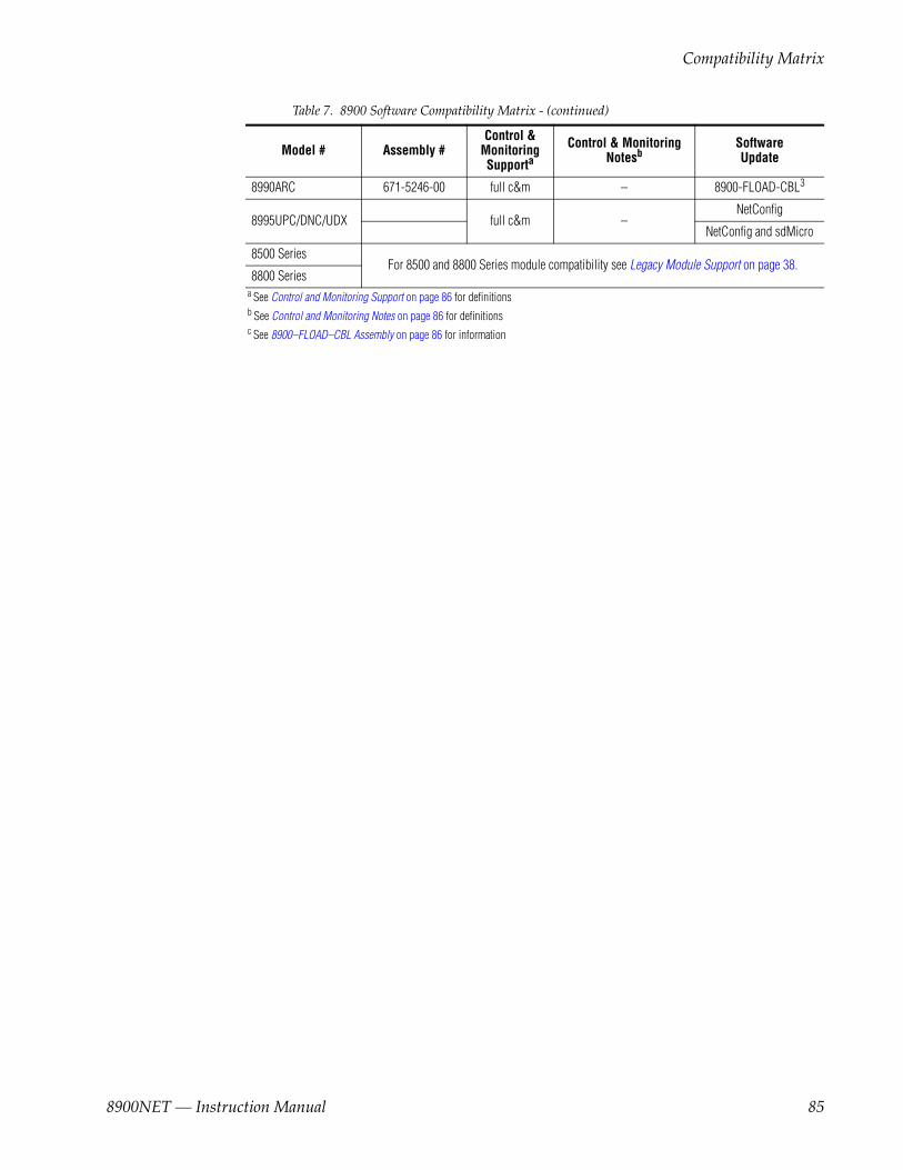
Compatibility Matrix
8990ARC 671-5246-00 full c&m – 8900-FLOAD-CBL3
8995UPC/DNC/UDX full c&m –NetConfig
NetConfig and sdMicro
8500 SeriesFor 8500 and 8800 Series module compatibility see Legacy Module Support on page 38.
8800 Series a See Control and Monitoring Support on page 86 for definitions b See Control and Monitoring Notes on page 86 for definitions c See 8900–FLOAD–CBL Assembly on page 86 for information
Table 7. 8900 Software Compatibility Matrix - (continued)
Model # Assembly #Control &
Monitoring Supporta
Control & Monitoring Notesb
SoftwareUpdate
8900NET — Instruction Manual 85

Appendix
Control and Monitoring SupportThe following abbreviations are used to indicate the features supported or not supported by the modules listed in Table 7:
• No comm — The module does not support any remote control or mon-itoring functions.
• Basic status — The module responds to only low-level probe from the Network module and only returns model number and description. Fault and signal presence are not reported. No control is supported.
• Full C&M — The module fully supports the control and monitoring system. The module reports status of all settings. The module can be configured remotely.
Control and Monitoring NotesThe following abbreviations are used in Table A-7 to indicate performance limitations for the listed legacy modules:
• Comm problem — The module shorts out the frame communication bus. When the problem module is installed, the NET module cannot communicate with any of the modules in slots 1 through 10.
• ID defects — The module is susceptible to ESD (electro-static discharge) damage of the module ID lines. If this damage occurs, the module will be reported as faulted on the frame status page and software download will not work.
• Faults not reported — The module may not report an error to the NET module even though its fault LED is on. The LED gives the correct fault status.
• Misleading status reported — The module does not support control and monitoring but indicates through a motherboard connection that it does. This module will show up as red on the frame status page even if it is working correctly.
8900–FLOAD–CBL AssemblySome modules require a cable assembly and software loading application for the software update process. This cable assembly and CD–ROM con-taining update software files can be ordered from Grass Valley. Contact your Grass Valley sales or service representative about ordering the 8900-FLOAD–CBL assembly.
86 8900NET — Instruction Manual

8900NET Software Update From FTP Server
8900NET Software Update From FTP ServerIf you are updating an 8900NET module with a software version earlier than version 3.2.0, you must use the following procedure.
FTP Method OverviewThe Modular Remote Monitoring and Control System is an extension of the Grass Valley Signal Management System (SMS) routing system and uses the same File Transfer Protocol (FTP) technique to download software.
Note This procedure assumes your Local FTP Server computer is a 32-bit Windows host running Win95, 98, NT or later.
If you do not have an FTP server, Grass Valley provides a free FTP server package that is easy to install and operate. This procedure assumes you will use the Xitami FTPD provided. If you already have an FTPD available, you can skip steps 3 through 5.
The software update process consists of the following steps:
1. Acquire the software update files and, if needed, the FTP Server package.
2. Place the module software update files into an FTPD modular directory.
3. Extract the FTP Daemon (Xitami FTPD).
4. Run the Xitami installation program.
5. Modify the FTPD configuration files to the Xitami directory.
6. Start the FTPD.
7. Use the 8900 GUI to initiate software updates.
Note When updating numerous Gecko 8900 modules, it is a good idea to dedicate one frame for the update process to avoid interrupting communication with active modules.
8. Verify the software update results.
8900NET — Instruction Manual 87

Appendix
FTP Software Update Procedure1. Acquire the software update files from Grass Valley (refer to Acquiring
Module Software Updates on page 64).
a. Create a temporary download directory on your PC:
c:\temp\
b. Using the web browser, select the desired .fld zipped file.
c. Click to download the .bin (8900NET only), .fld (8900 media modules) or zipped file. You are queried to either OPEN the file or SAVE AS. Select the SAVE AS option and set the path to the temporary directory on your computer.
This process will trigger the download of the file to your computer.
Note If you have access to an existing FTP Server’s directory, the module update files can be downloaded directly into that directory.
2. Move or extract the module update files into an FTPD modular directory.
The module software update files must reside in a directory that the FTPD can access. The Grass Valley supplied FTPD is configured to access a directory designated:
\modular\8900
The new software for the 8900NET module (version 3.2.0 and later) will be a binary file (.bin extension) or a field update files (.fld extension).
a. Open Windows Explorer on the local server computer.
b. If one does not already exist, create a directory on the C drive:
c:\modular\8900
c. Double-click the module software.exe file (in the temporary directory) and save it to the appropriate directory. The resulting file will be a .bin or .fld:
c:\modular\8900\8900net_sw400a_fw1.bin
Note The file name shown indicates: 8900NET, software version 4.00, firmware version 1.0.
3. Extract the FTPD (Xitami FTP Server) files.
88 8900NET — Instruction Manual

8900NET Software Update From FTP Server
Note This section is for facilities that do not already have an FTP Daemon (FTPD), also known as a File Transfer Protocol (FTP) Server, installed on the Gecko 8900 frame’s network. For those facilities that already have an FTPD or other FTP Service available in their network, go to step 6.
Grass Valley provides a free FTP server for those facilities that do not have a local FTP service. The FTP server package is the same Xitami Web Server-FTP package that is provided with the Grass Valley SMS router upgrade package. The version of the Xitami Web-FTP server dis-tributed with module software upgrades is for a 32-bit Windows host.
The FTP Daemon in the temporary directory is a self-extracting file (ftpd.exe). To extract the files:
a. Open Windows Explorer and find the ftpd.exe file.
b. Double click on the .exe file and extract the files to C:\temp.
These files will be extracted:
• xic3223c.exe – the Xitami installation file,
• defaults.cfg – an FTPD configuration file that has been modified specifically for Grass Valley software downloads, and
• ftpusers.sms – the FTPD’s admin file specifying user names and passwords network access to files in the ftp server directories.
4. Run the Xitami installation program.
a. Double Click on xic3223c.exe. You will see the Xitami Welcome (Figure 48). Click on Next >.
Figure 48. Xitami Web Server Welcome
8900NET — Instruction Manual 89

Appendix
b. You will see the Xitami Installation Notes (not shown). Click on Next >.
c. You will see Select Destination Directory (Figure 49). Do not change the default settings. Click on Next >
Figure 49. Select Destination Directory
d. You will see the Select Program Group screen (Figure 50). Do not change the default settings. Click on Next >.
Figure 50. Select Program Group
90 8900NET — Instruction Manual
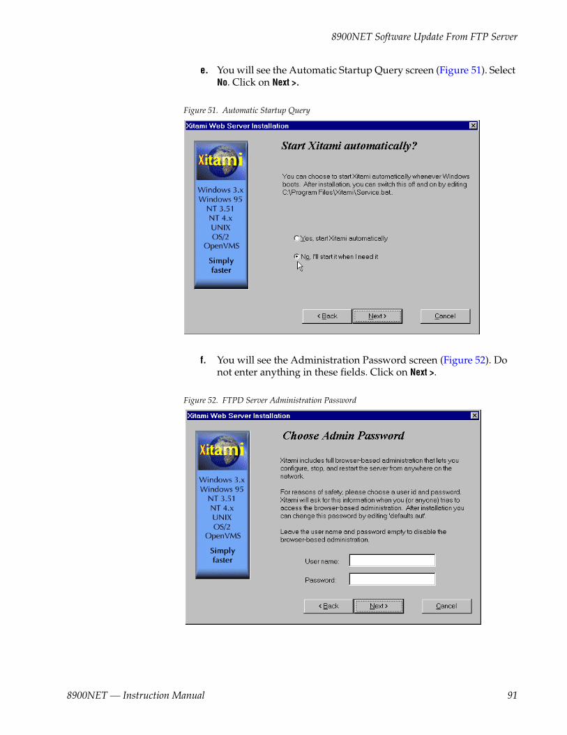
8900NET Software Update From FTP Server
e. You will see the Automatic Startup Query screen (Figure 51). Select No. Click on Next >.
Figure 51. Automatic Startup Query
f. You will see the Administration Password screen (Figure 52). Do not enter anything in these fields. Click on Next >.
Figure 52. FTPD Server Administration Password
8900NET — Instruction Manual 91
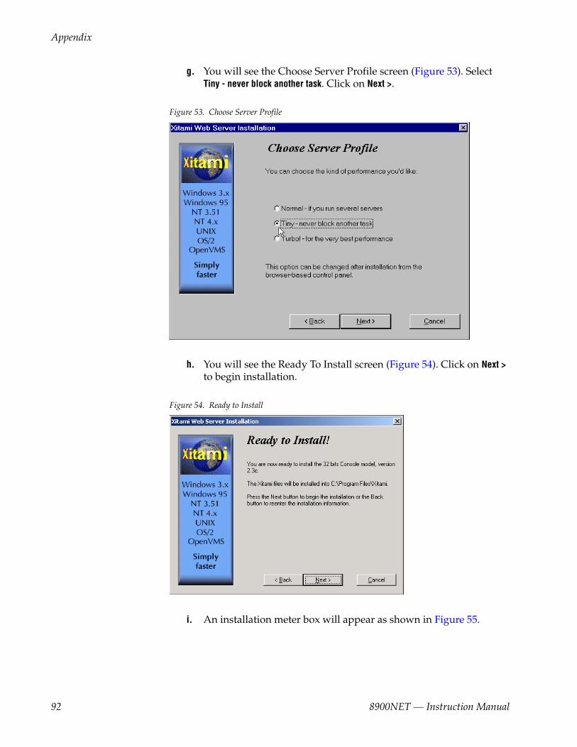
Appendix
g. You will see the Choose Server Profile screen (Figure 53). Select Tiny - never block another task. Click on Next >.
Figure 53. Choose Server Profile
h. You will see the Ready To Install screen (Figure 54). Click on Next > to begin installation.
Figure 54. Ready to Install
i. An installation meter box will appear as shown in Figure 55.
92 8900NET — Instruction Manual

8900NET Software Update From FTP Server
Figure 55. Installation Meter Box
j. Upon completion, you will see the Installation Complete! screen (Figure 56). Click on Finish.
Figure 56. Installation Complete
An Icon (see Figure 57) will have been created in the Program Group window that was selected during installation (see Figure 50 on page 90).
8900NET — Instruction Manual 93

Appendix
Figure 57. FTPD Icon in Program Group Window
5. Move the FTP Daemon Start-up Configuration Files.
The FTP Daemon has now been installed and requires configuration files be placed in the Xitami directory.
a. Open Windows Explorer.
b. From the Explorer window, return to the FTPD directory and move the extracted defaults.cfg and ftpusers.sms files to the directory at:
c:\Program Files\Xitami
The defaults.cfg and the ftpusers.sms files contain default configu-ration instructions that the FTPD application reads at start-up.
6. Start the FTPD.
If the Xitami Web Server (FTPD) is not already running, start it.
a. Click on the Start popup window on the PC.
94 8900NET — Instruction Manual

8900NET Software Update From FTP Server
b. Select PROGRAMS, then INTERNET TOOLS, and click on Xitami Web Server – 32 bit console (Figure 57 on page 94).
The Xitami Console will open as a DOS window. There will be a log of events, at least one of which will indicate it is accepting connec-tions (see Figure 58).
Figure 58. Typical FTPD Console Screen
The IP Address line should actually indicate the IP address of the PC you are using for the FTP server. This is the IP Address that will be used to initiate the software update.
The line that verifies that the FTPD is running reads:
ready for FTP connections on port 21
8900NET — Instruction Manual 95

Appendix
Password Protection for Software UpgradesThe FTPD distributed for software downloads provides user name and password protection for software updates. User name and password entry is required in the Software Update web pages.
The assignment of user names and passwords for a given FTP root direc-tory is administered by editing the ftpuser.sms file included in the FTPD distribution (see Step 3 of this procedure). This file initially contains the default user name and password (user name: moduser, password: moduser) for access to the modular root directory and instructions for setting up an account.
The contents of the file are shown in Figure 59. (The file also includes the SMS7000 account for customers with Thomson Grass Valley SMS routers.)
Figure 59. User Name and Password File ftpuser.sms
Note The FTPD configuration files should be installed in a password protected directory.
96 8900NET — Instruction Manual

8900NET Software Update From FTP Server
Upgrading SoftwareWith the FTPD running, use the 8900 GUI to initiate software updates. Use the web-browser to:
• Access the appropriate Software Update page for a given module,
• Enter the required data into the HTML Form on that page, and
• Submit the form.
The 8900 frame uses the data in the form to contact the FTPD on the server, download the update file, and reprogram the targeted module.
Note Prior to attempting update of software, refer to the target module’s manual and confirm that the Remote/Local Only jumper is in the Remote position.
Note To monitor the progress of the download, you may use the serial port con-nection (see Figure 60 on page 98) with a computer running a terminal emu-lation application.
8900NET — Instruction Manual 97

Appendix
Figure 60. Serial Port Console and PC Network Connections
Serial Connection for console interfaceComm. Parameters: 9600 baud, 8 bits, parity-none, 1 stop, flow-none
Comm 1 orComm 2 port
RS-232
PC running Hyperterm Terminal Emulation
PC running web browser GUI
8900TFN Frame
0612 -29r1
Ethernet
8900TFN Frame
RJ-45connector
To PC network cardRJ-45 connector
Ethernet Hub
98 8900NET — Instruction Manual
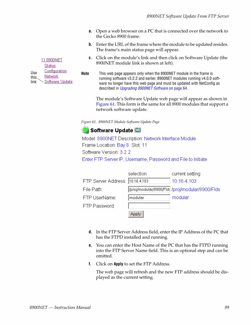
8900NET Software Update From FTP Server
a. Open a web browser on a PC that is connected over the network to the Gecko 8900 frame.
b. Enter the URL of the frame where the module to be updated resides. The frame’s main status page will appear.
c. Click on the module’s link and then click on Software Update (the 8900NET module link is shown at left).
Note This web page appears only when the 8900NET module in the frame is running software v3.2.2 and earlier. 8900NET modules running v4.0.0 soft-ware no longer have this web page and must be updated with NetConfig as described in Upgrading 8900NET Software on page 64.
The module’s Software Update web page will appear as shown in Figure 61. This form is the same for all 8900 modules that support a network software update.
Figure 61. 8900NET Module Software Update Page
d. In the FTP Server Address field, enter the IP Address of the PC that has the FTPD installed and running.
e. You can enter the Host Name of the PC that has the FTPD running into the FTP Server Name field. This is an optional step and can be omitted.
f. Click on Apply to set the FTP Address.
The web page will refresh and the new FTP address should be dis-played as the current setting.
Usethislink
8900NET — Instruction Manual 99

Appendix
g. In the File Path field, enter the FTP file path of the software update file.
The FTP file paths use forward slashes. The directory name “/mod-ular” is not needed in the path name.
h. Submit the form and start the update process by entering the user name and password and clicking on Apply.
By default, the Xitami Server has been configured to accept a user name of “moduser” and a password of “moduser” for the modular root directory. This may be changed by modifying the ftpusers.sms file in the C:\Program Files\Xitami directory (see Password Protec-tion for Software Upgrades on page 96).
After you click on Apply, the web page will be reloaded, displaying the Progress Monitor (Figure 62).
If an incorrect file name or password is entered, the Progress Monitor will report the condition and allow you to go back to the Software download page and re-enter the correct information.
The module software compatibility check uses compatibility infor-mation included in the Field Update File to ensure that the new soft-ware was intended for this module. In the event that there is a mismatch, the Net Board will abort the upgrade.
Note Do not make any changes to the web page during the software download.
i. If the file entered in the file path is invalid or the file cannot be found, a File Not Found message will appear in the Progress Monitor Results line (Figure 62). Select the Software Download link or the Refresh button to refresh the page to return to the download page and re-enter the file name.
Figure 62. 8900NET Software Download Progress Monitor
100 8900NET — Instruction Manual

8900NET Software Update From FTP Server
j. If the login password is incorrect, the Progress Monitor will report with a Login Incorrect message as shown in Figure 63. Select the Software Download link or refresh the page to return to the download page and re-enter the correct login.
Figure 63. Login Incorrect
k. Once the download has started and there are no error messages, wait for the Success screen to appear, then click on Software Update or the Refresh button again to refresh the page.
Note Do not click anywhere on the web page while the download is in progress unless you receive a File Not Found or Login Incorrect Results message.
Once the download is successful, the Progress Monitor will report a Success message similar to Figure 64.
Figure 64. 8900NET Software Update Failure Notice
l. Verify the software update results by checking the Installed Software Version in Properties portion of the 8900NET Status web page.
The software and firmware (if applicable) numbers should match that indicated in the .bin or .fld file name (see Step 2 of this proce-dure for file names and version numbers).
8900NET — Instruction Manual 101

Appendix
Unsupported Software UpdatesIf the 8900 module does not support network software updates, the Soft-ware Update web page may indicate software updating is not supported as shown in Figure 65.
These modules require a special cable kit (8900-FLOAD-CBL with Instruc-tion Manual) available from Grass Valley Sales or Service to perform a soft-ware update. Details for the module will be available in the specific module release notes that accompany the upgrade.
Note Always read the Release Notes for the specific module for the latest software download procedure before attempting to download software.
Figure 65. Software Update Not Supported
102 8900NET — Instruction Manual
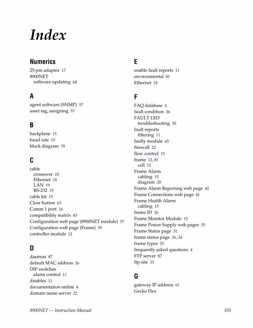
Index
Numerics25-pin adaptor 178900NET
software updating 64
Aagent software (SNMP) 57asset tag, assigning 57
Bbackplane 13baud rate 15block diagram 78
Ccable
crossover 18Ethernet 18LAN 19RS-232 15
cable kit 15Clear button 63Comm 1 port 16compatibility matrix 83Configuration web page (8900NET module) 57Configuration web page (Frame) 39controller module 12
Ddaemon 87default MAC address 26DIP switches
alarm control 11disables 11documentation online 4domain name server 22
Eenable fault reports 11environmental 81Ethernet 18
FFAQ database 4fault condition 36FAULT LED
troubleshooting 30fault reports
filtering 11faulty module 65firewall 22flow control 15frame 12, 81
cell 12Frame Alarm
cabling 15diagram 28
Frame Alarm Reporting web page 42Frame Connections web page 41Frame Health Alarm
cabling 15frame ID 26Frame Monitor Module 15Frame Power Supply web pages 55Frame Status page 31frame status page 26, 34frame types 25frequently asked questions 4FTP server 87ftp site 33
Ggateway IP address 61Gecko Flex
8900NET — Instruction Manual 103

Index
8900NET installation 12frame connectors 14
Grass Valley web site 4
Iinitial configuration 22Internal Module Healthbus control
overview 42using 45
Internet Explorer 25IP Address
setting 22storage 25
LLED indicators 20LED Reporting
8900NET front edge LEDs 20LED Reporting web page 48link list 34local area network (LAN) 10Locate Frame function
from Frame Configuration web page 39using NetConfig 39
locate module 62LogPrint procedure 73
MMAC (machine) address 26module
installation 12module compatibility 83Module Health Bus
conditions 29overview 28
module slot names 62Module Status page 31
Nnavigation 34NET module reboot 61NetConfig application 22
acquiring from ftp site 64feature 9
Netscape Navigator 25network addresses 61network configuration storage 25network conflicts 26network identity 22network parameters 22
establishing 22network traffic delays 22Network web page (8900NET module) 61NIM LED 20
Oon-board configuration switches 56online documentation 4
Pparity 15point-to-point 10, 18point-to-point communication 22power 81power supply 12
identifying part number 52power supply slot 55Power Supply Status web pages 55power supply, frame
web pages 55Power Supply/Demand web page 52
Rreboot 61reboot button 57, 61repair depot 65RJ-45 18RS-232 15, 22
Sservice information 65Slot Config web page
media modules 62
104 8900NET — Instruction Manual
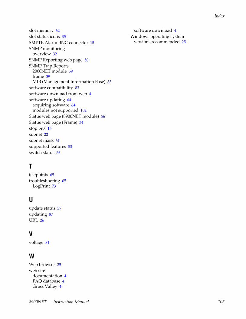
Index
slot memory 62slot status icons 35SMPTE Alarm BNC connector 15SNMP monitoring
overview 32SNMP Reporting web page 50SNMP Trap Reports
2000NET module 59frame 39MIB (Management Information Base) 33
software compatibility 83software download from web 4software updating 64
acquiring software 64modules not supported 102
Status web page (8900NET module) 56Status web page (Frame) 34stop bits 15subnet 22subnet mask 61supported features 83switch status 56
Ttestpoints 65troubleshooting 65
LogPrint 73
Uupdate status 37updating 87URL 26
Vvoltage 81
WWeb browser 25web site
documentation 4FAQ database 4Grass Valley 4
software download 4Windows operating system
versions recommended 25
8900NET — Instruction Manual 105

Index
106 8900NET — Instruction Manual


