888–THINBIT 888–THINFAX THINBIT · OUTSIDE THE U.S.A. Shipments are made by United Parcel...
130
thinbit.com 2018 SINCE 1964 888–THINBIT | 888–THINFAX | THINBIT.COM MADE IN THE USA GROOVING THREADING PARTING BORING TURNING FACE GROOVING CUSTOM TOOLING FORM TOOLING MILL TOOLING
-
Upload
hoangnguyet -
Category
Documents
-
view
216 -
download
0
Transcript of 888–THINBIT 888–THINFAX THINBIT · OUTSIDE THE U.S.A. Shipments are made by United Parcel...

thinbit.com2018
SINCE 1964
888–THINBIT | 888–THINFAX | THINBIT.COM
MADE IN THE USA
GROOVING THREADING PARTING BORING TURNING FACE GROOVINGCUSTOM TOOLINGFORM TOOLINGMILL TOOLING

GROOVING AND TURNING
.004” THROUGH .150” IN .001” INCREMENTS
1.000” DEPTH OF CUT
2, 3, 4, 5 AND 6MM INSERT WIDTHS
PG1-13
INTERNAL AND EXTERNAL
MULTI - INSERT
PG8-7
MAJOR DIAMETERS FROM .787”; 1” D.O.C.; 2, 3, 4, 5 AND
6MM INSERT WIDTHS
PG2-15
MAJOR DIAMETERS FROM .300”.004” THROUGH .150” IN
.001” INCREMENTS
PG2-9
MAJOR DIAMETERS FROM .300”.004” THROUGH .150” IN
.001” INCREMENTS
PG2-9
INTERNAL AND EXTERNAL CHAMFERING
45°
PG4-13
INTERNAL AND EXTERNAL THREADING
8 THREADS PER INCH AND GREATER
UP TO 1” MATERIAL
.025”, .045”, .062”, .085”, .115” INSERT WIDTHS
PG5-3
SECTION 1: GROOVING
SECTION 2: FACE GROOVING
SECTION 4: THREADING AND CHAMFERING
SECTION 5: PARTING MADE IN USA SINCE 1964
OVER 100,000 TOOLS IN STOCK FORGROOVING • THREADING • PARTING
BORING • TURNING • FACE GROOVING SPECIALS • FORM TOOLS
SECTION 1
SECTION 2
SECTION 4
SECTION 5
CH
UC
K
KAISER TOOL COMPANY, INC.3620 CENTENNIAL DRIVE
FORT WAYNE, IN 46808
WWW.THINBIT.COM/CATALOGHOWTO FOR INFORMATION ON HOW TO USE THIS
CATALOG SCAN THIS CODE.
PG1-9
STATIC O-RING GROOVING WITH 1.250” MINIMUM BORE DIAMETER
PG1-13
PG2-11
MAJOR DIAMETERS FROM .300”; FOR DOVETAIL O-RING
FACE GROOVING
60° PG 4-9 A PG 4-11
ACME EXTERNAL THREADING
4 THREADS PER INCH AND GREATER

TOOLHOLDERSSECTION 7
MODIFICATIONSSECTION 8
TECHNICALSECTION 9
LITTLEBIT®
SECTION 10
SECTION 1: GROOVING
PG1-3
.125” MINIMUM BORE DIAMETER
.004” THROUGH .250” IN .001” INCREMENTS
PG1-5
.325” MINIMUM BORE DIAMETER.004” THROUGH .125” IN .001” INCREMENTS
PG1-7
1.000” MINIMUM BORE DIAMETER; 2MM, 3MM AND 4MM
INSERT WIDTHS
SECTION 2: FACE GROOVING
PG2-3
MAJOR DIAMETERS FROM .125”.004” THROUGH .250” IN .001” INCREMENTS
PG2-5
MAJOR DIAMETERS FROM .415”.004” THROUGH .125” IN .001” INCREMENTS
PG2-7
MAJOR DIAMETERS FROM 1.574”2, 3, 4, 5 AND 6MM
INSERT WIDTHS
SECTION 3: BORING
FOR MORE COMPLETE
APPLICATION REFERENCE
CHARTS, REFER TO
PAGES 9-3 & 9-4
CH
UC
K
SECTION 1
SECTION 2
SECTION 3
SECTION 4
www.thinbit.comE-MAIL: [email protected]
ORDERS: [email protected] QUOTES: [email protected]
PG3-3
.073” MINIMUM BORE DIAMETERSOLID CARBIDE TOOLING
PG3-5
.125” MINIMUM BORE DIAMETER PROFILING
SOLID CARBIDE TOOLING
R PG 3-7F PG 3-11
.165” MINIMUM BORE DIAMETERCD, TD, TP AND WCGT INSERT
STYLES
SECTION 4: THREADING
60° PG 4-3
.077” MINIMUM BORE DIAMETER
4 THREADS PER INCH AND GREATER
PG4-7
.325” MINIMUM BORE DIAMETER
9 THREADS PER INCH AND GREATER
Phone: 888-THINBIT
(888-844-6248)
(260) 484-3620
Fax: 888-THINFAX
(888-844-6329)
(260) 482-1881
ACME PG 4-5
.187” MINIMUM BORE DIAMTER
6 THREADS PER INCH AND GREATER

COMPLETE TOOLING SOLUTIONS FORGROOVING • THREADING • PARTING • BORING • TURNING
FACE GROOVING • SPECIALS • FORM TOOLS
®®®
®

KAISER TOOL COMPANY, INC.3620 Centennial Drive • Fort Wayne, IN 46808P.O. Box 80430 • Fort Wayne, IN 46898-0430
Phone: 888-THINBIT (888-844-6248) • (260) 484-3620Fax: 888-THINFAX (888-844-6329) • (260) 482-1881
Kaiser Tool Company, Inc. has made every effort to produce a catalog that is accurate and error free. Kaiser Tool Company, Inc. is not responsible for any loss due to errors or changes in product specifications.
For the most accurate and up to date information, contact our sales office.
Web: www.thinbit.comGeneral E-mail: [email protected]
Orders: [email protected] Quotes: [email protected]
Our business hours are 7:30 am to 5:00 pm Eastern Standard Time.Processing for same day shipment stops at 3:00 pm EST.
OUTSIDE THE U.S.A.
Shipments are made by United Parcel Service. Ground service will be used (air for Alaska, Hawaii and U.S. Territories) unless otherwise specified by the customer. Shipments can be made via other carriers when customer provides shipping account number.
PRICING:
SHIPMENT:
TERMS: Master Card, Visa, Discover, American Express and C.O.D. accepted. F.O.B. Fort Wayne, Indiana.No minimum order on standard items. We collect sales tax in California only.
Current pricing is available online at: http://www.thinbit.com/price list.Items cannot be combined for quantity prices.A shipping and handling fee applies to all orders.Prices for tooling modifications will be given in writing. Pricing and availability on orders are confirmed to customer.
RETURNS: Returns are accepted for credit within 30 days of receipt of order and with prior written approval. All returns are subject to a 15% restocking charge. All returned goods must be in 'like-new' condition and returned in their original packaging. All claims for damaged goods or incorrect items must be made within 48 hours of receipt of order.
HOURS:
TERMS: Cash in advance until credit is established. Payment via Master Card, Visa, Discover, American Express, or bank to bank transfer in U.S. funds. F.O.B. Fort Wayne, Indiana, U.S.A.Please notify us prior to remittance to confirm total amount including shipping charges.Shipments made outside the U.S.A. are shipped via United Parcel Service. Shipments can be made via other carriers when customer provides shipping account number.
30 day net credit for approved accounts.Accounts must re-establish credit after 18 months of inactivity.
CREDIT:
GENERAL INFORMATION
5

To use this index: Match the first few characters from your invoice or tool to the 'Product Code'.
6
Product Code Description Page
LGTF GROOVE 'N TURN® Face Grooving Insert 2-10LGTT GROOVE 'N TURN® Threading Insert 4-10LHA LITTLEBIT® Hardinge Toolholder 10-5LPT LITTLEBIT® Parting Insert 10-2LRE LITTLEBIT® Reversible Toolholder 10-7LREH LITTLEBIT® Reversible Head 10-7LRI LITTLEBIT® 90º Reversible Toolholder 10-7LRIH LITTLEBIT® 90° Reversible Head 10-7LR0 GROOVE 'N TURN® Round Internal Toolholder 7-8;10-8LROE GROOVE 'N TURN® Rnd Reversible Toolholder/Head 7-7;10-8LSET LITTLEBIT® Grooving Insert Set 10-4LSS LITTLEBIT® Swiss Toolholder 10-6LSSFG GROOVE 'N TURN® Swiss Face Groove Toolholder 7-6;10-6LTT LITTLEBIT® Threading Insert 10-3MBA MINI-BORE® Boring Bar 3-13MBAI MINI-BORE® Insert 3-14MBB MINI-BORE® Boring Bar 3-15MBBI MINI-BORE® Insert 3-16MBC MINI-BORE® Boring Bar 3-17MBCI MINI-BORE® Insert 3-18MBE MINI-BORE® TRIGON® Boring Bar 3-8MBEI MINI-BORE® TRIGON® Insert 3-8MBF MINI-BORE® TRIGON® Boring Bar 3-9MBFI MINI-BORE® TRIGON® Insert 3-9MBG MINI-BORE® TRIGON® Boring Bar 3-10MBGI MINI-BORE® TRIGON® Insert 3-10MBZ MINI-BORE® Boring Bar 3-12MBZI MINI-BORE® Insert 3-12MGC Mini GROOVE 'N TURN® Clamp 1-6;2-6MGT Mini GROOVE 'N TURN® ID Toolholder 1-6MGTF Mini GROOVE 'N TURN® Face Grooving Toolholder 2-6MGTI Mini GROOVE 'N TURN® Insert 1-5;2-5MGTT Mini GROOVE 'N TURN® Threading Insert 4-8PT MICROBIT® Profi ling Tool 3-6ROM LITTLEBIT® Multi-Insert Toolholder Round 7-10RROE GROOVE 'N TURN® Round Reversible Shank 7-7;10-8RS LITTLEBIT® Reversible Shank 10-7RT MICROBIT® Reverse Profi ling Tool 3-6S45 LITTLEBIT® 45º Toolholder 10-9SFT LITTLEBIT® Flushtop Toolholder 10-5SGB LITTLEBIT® Insert Blank 10-4SGI LITTLEBIT® Grooving Insert 10-1SGP LITTLEBIT® Parting Insert Blank 10-4SHA LITTLEBIT® Hardinge Toolholder 10-5SPT LITTLEBIT® Parting Insert 10-2SRE LITTLEBIT® Reversible Toolholder 10-7SREH LITTLEBIT® Reversible Head 10-7SRI LITTLEBIT® 90° Reversible Toolholder 10-7SRIH LITTLEBIT® 90° Reversible Head 10-7SR0 LITTLEBIT® Round Internal Toolholder 10-8SROE LITTLEBIT® Round Reversible Toolholder/Head 10-8SSET LITTLEBIT® Grooving Insert Set 10-4SSS LITTLEBIT® Swiss Toolholder 10-6SSSFG LITTLEBIT® Swiss Face Groove Toolholder 10-6STT LITTLEBIT® Threading Insert 10-3TT MICROBIT® Threading Tool 4-4
Product Code Description Page
AD Round & Square Adapters 7-2AT MICROBIT® ACME Threading Tool 4-6BT MICROBIT® Boring Tool 3-4Clamp A Clamp 10-5,6Clamp C Clamp Section 7, 10Clamp M Clamp 7-9Clamp N Clamp 7-9Clamp Q Clamp 7-12Clamp R Clamp 7-12Clamp X Clamp 7-3,12Clamp Y Clamp 7-3,12CN Custom Made Tooling CallDGC DEEPGROOVE® Clamp 1-8,14;2-8,16;7-13,14DGH DEEPGROOVE® Head 1-14;2-8,16;7-13,14DGI DEEPGROOVE® Insert 6-2DGMI DEEPGROOVE® Insert 6-2DGPA DEEPGROOVE® Tooling Package 2-16DGPB DEEPGROOVE® Tooling Package 2-16DGPC DEEPGROOVE® Tooling Package 2-16DGPD DEEPGROOVE® Tooling Package 2-16DGPE DEEPGROOVE® Tooling Package 1-14DGPF DEEPGROOVE® Tooling Package 1-14DGPG DEEPGROOVE® Tooling Package 1-14DGPH DEEPGROOVE® Tooling Package 1-14DGPM DEEPGROOVE® Tooling Package 2-8DGPN DEEPGROOVE® Tooling Package 2-8DGPO DEEPGROOVE® Tooling Package 7-13DGPP DEEPGROOVE® Tooling Package 7-13DGPQ DEEPGROOVE® Tooling Package 7-13DGPR DEEPGROOVE® Tooling Package 7-13DGPS DEEPGROOVE® Tooling Package 7-14DGPT DEEPGROOVE® Tooling Package 7-14DGPU DEEPGROOVE® Tooling Package 7-14DGPV DEEPGROOVE® Tooling Package 7-14DGPZ DEEPGROOVE® Tooling Package 1-8DGS DEEPGROOVE® Shank 1-14;2-8,16;7-13,14DGT DEEPGROOVE® Shank 1-8EM FORM-A-GROOVE® Multi-Insert Toolholder 7-9ESM FORM-A-GROOVE® Multi-Insert Shank 7-9FT MICROBIT® Face Grooving Tool 2-4GT MICROBIT® Grooving Tool 1-4HM LITTLEBIT® Multi-Insert Pocket 7-9L36 GROOVE 'N TURN® 30º/60° Toolholder 7-12L45 GROOVE 'N TURN® 45º Toolholder 7-12;10-9LFT LITTLEBIT® Flushtop Toolholder 10-5LGAT GROOVE 'N TURN® ACME Threading Insert 4-12LGB LITTLEBIT® Insert Blank 10-4LGDT GROOVE 'N TURN® Dovetail Face Grooving Insert 2-12LGI LITTLEBIT® Grooving Insert 10-1LGOR GROOVE 'N TURN® Static O-Ring OD Insert 1-12LGORF GROOVE 'N TURN® Static O-Ring Face Insert 2-14LGP LITTLEBIT® Parting Insert Blank 10-4LGPT GROOVE 'N TURN® Parting Insert 5-4LGS GROOVE 'N TURN® OD Toolholder 7-3LGSF GROOVE 'N TURN® Face Grooving Toolholder 7-4LGT45 GROOVE 'N TURN® Chamfering Insert 4-14LGT GROOVE 'N TURN® Grooving Insert 1-10;2-10
PRODUCT INDEX

KAISER TOOL COMPANY, INC.Phone: 888-THINBIT (888-844-6248) or (260) 484-3620 • Fax: 888-THINFAX (888-844-6329) or (260) 482-1881www.thinbit.com • General E-mail: [email protected] • Orders: [email protected] • Quotes: [email protected]
DISCONTINUED PRODUCT INDEX
PLEASE NOTE:The following products have been discontinued from our standard catalog. Stock delivery is limited to quantity on hand at time of order. For out of stock products, delivery will be determined at time of order.
Please call for any products on the discontinued list below. We may be able to substitute or design a special application.
To use this index: Match the first few characters from your invoice or tool to the 'Product Code'
Product Code Description
Clamp B ClampClamp D ClampClamp E ClampClamp G ClampClamp H ClampClamp I ClampClamp J ClampClamp L ClampClamp O ClampClamp P ClampClamp S ClampClamp T ClampEM34 LITTLEBIT® Multi-Insert ToolholderESM34 LITTLEBIT® Multi-Insert ShankGTSET GROOVE 'N TURN® Insert SetHM34 LITTLEBIT® Multi-Insert PocketLFG LITTLEBIT® Face Grooving InsertLME MINIBIT® External ToolholderLMF MINIBIT® Face Grooving ToolholderLMGI MINIBIT® Grooving InsertLMI MINIBIT® Internal ToolholderLMSET MINIBIT® Insert SetsLMSF MINIBIT® Face Grooving InsertLMSG MINIBIT® Shoulder Grooving InsertLMTT MINIBIT® Threading InsertLSF LITTLEBIT® Shoulder Face Grooving InsertLSG LITTLEBIT® Shoulder Grooving InsertMBBH4 MINI-BORE® Boring BarMBBS4 MINI-BORE® Boring Bar
OVER 100,000 TOOLS IN STOCK FORGROOVING • THREADING • PARTING • BORING
TURNING • FACE GROOVINGSPECIALS • FORM TOOLS
7
Product Code Description
MBBSQ MINI-BORE® Boring Bar
MBCSQ MINI-BORE® Boring Bar
MBCH4 MINI-BORE® Boring Bar
MBCS4 MINI-BORE® Boring Bar
MBP MINI-BORE® Coolant Adapter
MMA MINI-BORE® Boring Bar
MMB MINI-BORE® Boring Bar
MSET Mini GROOVE 'N TURN® Insert Set
SFG LITTLEBIT® Face Grooving Insert
SME MINIBIT® External Toolholder
SMF MINIBIT® Face Grooving Toolholder
SMGI MINIBIT® Grooving Insert
SMI MINIBIT® Internal Toolholder
SMSET MINIBIT® Insert Sets
SMSF MINIBIT® Shoulder Face Grooving Insert
SMSG MINIBIT® Shoulder Grooving Insert
SMTT MINIBIT® Threading Insert
SSF LITTLEBIT® Face Grooving Insert
SSG LITTLEBIT® Grooving Insert
XFG LITTLEBIT® Face Grooving Insert
XGB LITTLEBIT® Insert Blank
XGI LITTLEBIT® Grooving Insert
XRE LITTLEBIT® Reversible Toolholder
XREH LITTLEBIT® Reversible Head
XRI LITTLEBIT® 90° Reversible Toolholder
XRIH LITTLEBIT® 90° Reversible Head
XR0 LITTLEBIT® Round Internal Toolholder
XSET LITTLEBIT® Grooving Insert Set
KAISER TOOL COMPANY, INC.Phone: 888-THINBIT (888-844-6248) or (260) 484-3620 • Fax: 888-THINFAX (888-844-6329) or (260) 482-1881www.thinbit.com • General E-mail: [email protected] • Orders: [email protected] • Quotes: [email protected]
Scan this code for additional information.
www.thinbit.com/qr1-1
GRO
OV
ING
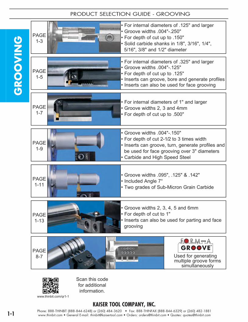
PRODUCT SELECTION GUIDE - GROOVING
PAGE 1-3
• For internal diameters of .125" and larger• Groove widths .004"-.250"• For depth of cut up to .150"• Solid carbide shanks in 1/8", 3/16", 1/4", 5/16", 3/8" and 1/2" diameter
PAGE 1-5
• For internal diameters of .325" and larger• Groove widths .004"-.125"• For depth of cut up to .125"• Inserts can groove, bore and generate profiles• Inserts can also be used for face grooving
PAGE 1-7
• For internal diameters of 1" and larger• Groove widths 2, 3 and 4mm• For depth of cut up to .500"
PAGE 1-9
• Groove widths .004"-.150"• For depth of cut 2-1/2 to 3 times width• Inserts can groove, turn, generate profiles and be used for face grooving over 3" diameters• Carbide and High Speed Steel
PAGE 1-11
• Groove widths .095", .125" & .142"• Included Angle 7°• Two grades of Sub-Micron Grain Carbide
PAGE 1-13
• Groove widths 2, 3, 4, 5 and 6mm• For depth of cut to 1"• Inserts can also be used for parting and face grooving
PAGE 8-7 Used for generating
multiple groove forms simultaneously

KAISER TOOL COMPANY, INC.Phone: 888-THINBIT (888-844-6248) or (260) 484-3620 • Fax: 888-THINFAX (888-844-6329) or (260) 482-1881www.thinbit.com • General E-mail: [email protected] • Orders: [email protected] • Quotes: [email protected] 1-2
TOOLING ORIENTATION GUIDE - GROOVING
External GroovingTop View
Tools show cutting edge up.
LeftHand
Counter-Clockwise
Clockwise
LeftHand
LeftHand
RightHand
RightHand
RightHand
Chu
ck
Internal GroovingTop View
Tools show cutting edge up.
Counter-Clockwise
Clockwise
LeftHand
RightHand
Chu
ck
GRO
OV
ING
KAISER TOOL COMPANY, INC.Phone: 888-THINBIT (888-844-6248) or (260) 484-3620 • Fax: 888-THINFAX (888-844-6329) or (260) 482-1881www.thinbit.com • General E-mail: [email protected] • Orders: [email protected] • Quotes: [email protected]
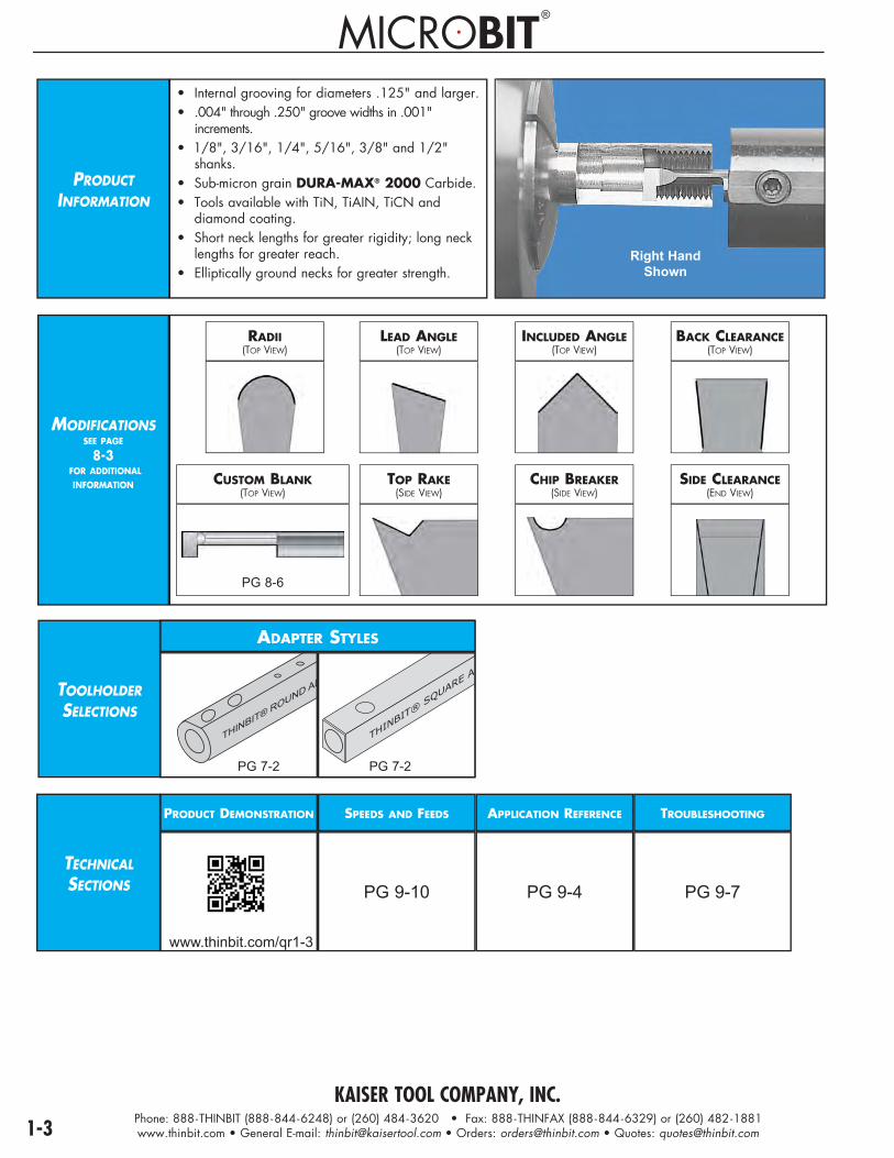
PRODUCTINFORMATION
• Internal grooving for diameters .125" and larger.• .004" through .250" groove widths in .001" increments.• 1/8", 3/16", 1/4", 5/16", 3/8" and 1/2" shanks.• Sub-micron grain DURA-MAX® 2000 Carbide.• Tools available with TiN, TiAIN, TiCN and diamond coating.• Short neck lengths for greater rigidity; long neck lengths for greater reach.• Elliptically ground necks for greater strength.
Right HandShown
MODIFICATIONSSEE PAGE
8-3 FOR ADDITIONAL
INFORMATION
RADII(TOP VIEW)
LEAD ANGLE(TOP VIEW)
CUSTOM BLANK(TOP VIEW)
TOP RAKE(SIDE VIEW)
INCLUDED ANGLE(TOP VIEW)
CHIP BREAKER(SIDE VIEW)
BACK CLEARANCE(TOP VIEW)
SIDE CLEARANCE(END VIEW)
TOOLHOLDERSELECTIONS
������������� �
����
����
��� ���
ADAPTER STYLES
PG 9-10
APPLICATION REFERENCESPEEDS AND FEEDS TROUBLESHOOTINGPRODUCT DEMONSTRATION
PG 9-4 PG 9-7
PG 8-6
PG 7-2 PG 7-2
www.thinbit.com/qr1-3
TECHNICALSECTIONS
®®

KAISER TOOL COMPANY, INC.Phone: 888-THINBIT (888-844-6248) or (260) 484-3620 • Fax: 888-THINFAX (888-844-6329) or (260) 482-1881www.thinbit.com • General E-mail: [email protected] • Orders: [email protected] • Quotes: [email protected] 1-4
I.D
.G
RO
OV
ING
I.D. GROOVING TOOLS
�
�
�
�
�
�
�������� ��������
FRONT RAKE: Primary 21°
BACK CLEARANCE: 2°
SIDE CLEARANCE: 2°
RADIUS: Sharp corner through full radius available
TOP RAKE: 0°
LEAD ANGLE: 0°'A' TOLERANCE: .004" - .250": +.0009"/-.0000"
ORDERING INSTRUCTIONS
Complete the ORDER CODE in the table below that represents your selection of groove width and tool dimensions.
EXAMPLE: The ORDER CODE for a 1/4" shank, right hand tool with an .080" tool width,
.110" depth of cut and .500" long neck is:GT40B 0 8 0 R
SPECIFICATIONS ORDER CODE INFORMATION
Minimum Bore& Shank Diameter
Tool WidthRange
Depth of Cut Neck Length
DURA-MAX® 2000 CarbideSee Page 9-10 for speeds and feeds
Add-onsUse 'Order Code' and Add
Overall Length
ToolholderPage 7-2
'C' 'A' 'B' 'E' FullRadiusPage8-3
CornerRadiusPage8-3
CoatingPage 9-6
'D' Use Toolholders Beginning
With Right Hand Left Hand
1/8" .004"-.063"
.004"-.006" = 3 x 'A' .250" GT20C _ _ _ R GT20C _ _ _ L
add 'FR'
Maximum radius
limited to depth of cut
* See Note
add'CR_ _ _'
(indicatesize in.xxx")
Maximum radius
limited to depth of cut
* See Note
TiNadd 'C'
TiCNadd 'D'
TiAlNadd 'E'
Diamondadd 'F'
1.365" + 'A' 'AD'.007"-.063" = .020" .375" GT21C _ _ _ R GT21C _ _ _ L
.004"-.016" = 3 x 'A' .250" GT20B _ _ _ R GT20B _ _ _ L
.017"-.063" = .050" .375" GT21B _ _ _ R GT21B _ _ _ L
3/16" .004"-.093"
.004"-.011" = 3 x 'A' .375" GT30C _ _ _ R GT30C _ _ _ L
1.865" + 'A' 'AD'.012"-.093" = .035" .625" GT31C _ _ _ R GT31C _ _ _ L
.004"-.026" = 3 x 'A' .375" GT30B _ _ _ R GT30B _ _ _ L
.027"-.093" = .080" .625" GT31B _ _ _ R GT31B _ _ _ L
1/4" .004"-.125"
.004"-.016" = 3 x 'A' .500" GT40C _ _ _ R GT40C _ _ _ L
2.365" + 'A' 'AD'.017"-.125" = .050" .750" GT41C _ _ _ R GT41C _ _ _ L
.004"-.036" = 3 x 'A' .500" GT40B _ _ _ R GT40B _ _ _ L
.037"-.125" = .110" .750" GT41B _ _ _ R GT41B _ _ _ L
5/16" .004"-.156"
.004"-.021" = 3 x 'A' .625" GT50C _ _ _ R GT50C _ _ _ L
2.330" + 'A' 'AD'.022"-.156" = .063" 1.000" GT51C _ _ _ R GT51C _ _ _ L
.004"-.046" = 3 x 'A' .625" GT50B _ _ _ R GT50B _ _ _ L
.047"-.156" = .140" 1.000" GT51B _ _ _ R GT51B _ _ _ L
3/8" .004"-.187".004"-.036" = 3 x 'A' .750" GT60C _ _ _ R GT60C _ _ _ L
2.800" + 'A' 'AD'.037"-.187" = .110" 1.250" GT61C _ _ _ R GT61C _ _ _ L
1/2" .004"-.250".004"-.050" = 3 x 'A' 1.000" GT80C _ _ _ R GT80C _ _ _ L
3.240" + 'A' 'AD'.051"-.250" = .150" 1.750" GT81C _ _ _ R GT81C _ _ _ L
Right Hand Illustrated
* Example: GT31C093R - max radius would be .035"
Specify the Tool Width 'A'
KAISER TOOL COMPANY, INC.Phone: 888-THINBIT (888-844-6248) or (260) 484-3620 • Fax: 888-THINFAX (888-844-6329) or (260) 482-1881www.thinbit.com • General E-mail: [email protected] • Orders: [email protected] • Quotes: [email protected]
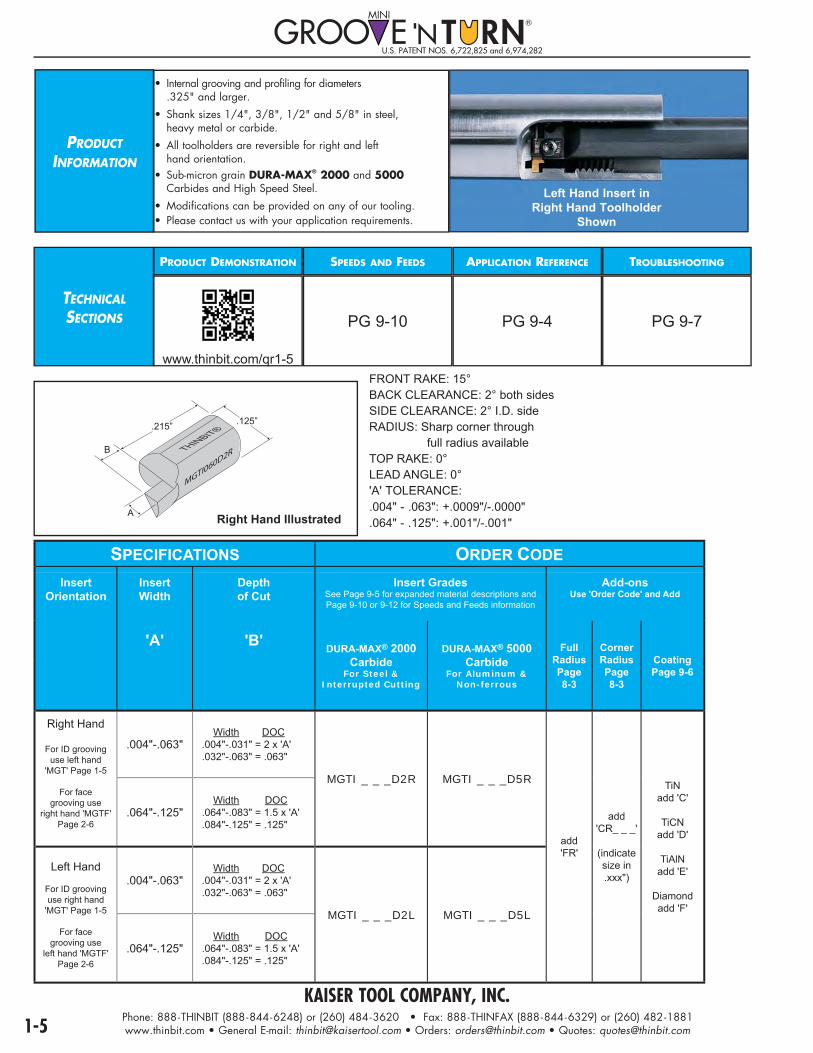
PRODUCTINFORMATION
• Internal grooving and profiling for diameters .325" and larger.
• Shank sizes 1/4", 3/8", 1/2" and 5/8" in steel, heavy metal or carbide.
• All toolholders are reversible for right and left hand orientation.• Sub-micron grain DURA-MAX® 2000 and 5000 Carbides and High Speed Steel.
• Modifications can be provided on any of our tooling. • Please contact us with your application requirements.
TECHNICALSECTIONS
PRODUCT DEMONSTRATION SPEEDS AND FEEDS
PG 9-10
APPLICATION REFERENCE
PG 9-4
TROUBLESHOOTING
PG 9-7
Right Hand Illustrated
MGTI0
60D2RTH
INBIT®
A
B
.125”.215”
FRONT RAKE: 15°BACK CLEARANCE: 2° both sidesSIDE CLEARANCE: 2° I.D. sideRADIUS: Sharp corner through full radius availableTOP RAKE: 0°LEAD ANGLE: 0°'A' TOLERANCE: .004" - .063": +.0009"/-.0000" .064" - .125": +.001"/-.001"
SPECIFICATIONS ORDER CODEInsert
OrientationInsertWidth
Depthof Cut
Insert GradesSee Page 9-5 for expanded material descriptions and Page 9-10 or 9-12 for Speeds and Feeds information
Add-onsUse 'Order Code' and Add
'A' 'B' DURA-MAX® 2000 Carbide
For Steel & Interrupted Cutting
DURA-MAX® 5000 Carbide
For Aluminum &Non-ferrous
FullRadiusPage8-3
CornerRadiusPage8-3
CoatingPage 9-6
Right Hand
For ID groovinguse left hand
'MGT' Page 1-5
For facegrooving use
right hand 'MGTF'Page 2-6
.004"-.063" Width DOC.004"-.031" = 2 x 'A'.032"-.063" = .063"
MGTI _ _ _D2R MGTI _ _ _D5R
add'FR'
add'CR_ _ _'
(indicatesize in.xxx")
TiNadd 'C'
TiCNadd 'D'
TiAlNadd 'E'
Diamondadd 'F'
.064"-.125" Width DOC.064"-.083" = 1.5 x 'A'.084"-.125" = .125"
Left Hand
For ID groovinguse right hand
'MGT' Page 1-5
For facegrooving use
left hand 'MGTF'Page 2-6
.004"-.063" Width DOC.004"-.031" = 2 x 'A'.032"-.063" = .063"
MGTI _ _ _D2L MGTI _ _ _D5L
.064"-.125" Width DOC.064"-.083" = 1.5 x 'A'.084"-.125" = .125"
Left Hand Insert in Right Hand Toolholder
Shown
www.thinbit.com/qr1-5
U.S. PATENT NOS. 6,722,825 and 6,974,282

KAISER TOOL COMPANY, INC.Phone: 888-THINBIT (888-844-6248) or (260) 484-3620 • Fax: 888-THINFAX (888-844-6329) or (260) 482-1881www.thinbit.com • General E-mail: [email protected] • Orders: [email protected] • Quotes: [email protected] 1-6
I.D
.G
RO
OV
ING
I.D. GROOVING TOOLS
1/2” MINI G
ROOVE ‘N TURN M
GT12HM-RB
Note: • All toolholders are reversible for right hand or left hand orientation.
• For grooving: Insert Width Depth of Cut .004"-.031" 2 x width .032"-.063" .063" .064"-.083" 1.5 x width .084"-.125" .125"
ORDERING INSTRUCTIONS
Select the ORDER CODE in the table below that represents your selection of tool specifications.EXAMPLE:
The ORDER CODE for a .575" minimum bore toolholder with a 1/2" steel shank is:MGT12
SPECIFICATIONS ORDER CODE INFORMATIONMinimum Bore Toolholder
MaterialToolholderPackage
Replacement Parts Overall Length
Shank Diameter
Inserts
'C' Extension Ratios:Steel: 4xø
Heavy Metal: 6xøCarbide: 8xø
Includes Shank, Clamp and Hardware
ClampOnly
ScrewOnly
WrenchOnly 'D' 'B' Use Inserts
Beginning With
.325".063" Insert Width Maximum
(Threading & Groove Widths .004"-.063")
Steel MGT14
MGC1 F31 W31
4.000"
1/4"
Grooving:'MGTI'
Page 1-5
Threading:'MGTT'
Page 4-8
Use right hand inserts for clockwise
orleft hand inserts
for counter-clockwise
Heavy Metal MGT14HM 3.965"
Carbide MGT14C 6.504"
.450".063" Insert Width Maximum
(Threading & Groove Widths .004"-.063")
Steel MGT38
MGC1 F31 W31
5.500"
3/8"Heavy Metal MGT38HM 5.485"
Carbide MGT38C 6.768"
.575"(Threading & Groove Widths .004"-.063")
or
.640"(Groove Widths .064"-.125")
Steel MGT12
MGC1 F31 W31
5.500"
1/2"
Heavy Metal MGT12HM 5.485"
.690"(Threading & Groove Widths .004"-.063")
or
.755"(Groove Widths .064"-.125")
Steel MGT58 MGC1 F31 W31 5.500" 5/8"
Right Hand Toolholder Orientation with Left Hand Insert Illustrated

KAISER TOOL COMPANY, INC.Phone: 888-THINBIT (888-844-6248) or (260) 484-3620 • Fax: 888-THINFAX (888-844-6329) or (260) 482-1881www.thinbit.com • General E-mail: [email protected] • Orders: [email protected] • Quotes: [email protected]
PRODUCTINFORMATION
• Internal grooving for diameters 1" and larger.
• 3/4" and 1" shank diameters.
• Right hand orientation standard.
• Short neck lengths for greater rigidity; long neck lengths for greater reach.
• Elliptical neck for increased strength and rigidity.
• Modifications can be provided on any of our tooling. Please contact us with your application requirements.
INSERTSELECTIONS
SEE PAGE 6-1
TECHNICALSECTIONS
PRODUCT DEMONSTRATION
www.thinbit.com/qr1-7
SPEEDS AND FEEDS
PG 9-10
APPLICATION REFERENCE
PG 9-4
TROUBLESHOOTING
PG 9-7
INSERT STYLES
Right HandShown
U.S. PATENT NO. 5,638,728
SHARP CORNER(TOP VIEW)
CORNER RADIUS(TOP VIEW)

KAISER TOOL COMPANY, INC.Phone: 888-THINBIT (888-844-6248) or (260) 484-3620 • Fax: 888-THINFAX (888-844-6329) or (260) 482-1881www.thinbit.com • General E-mail: [email protected] • Orders: [email protected] • Quotes: [email protected] 1-8
I.D. GROOVING TOOLS
I.D
.G
RO
OV
ING
Right Hand Illustrated
SPECIFICATIONS ORDER CODE INFO.
Minimum Bore
Insert Width
Depth of Cut
NeckLength
ShankDiameter
ToolholderPackage
Includes Shank, Clamp and Hardware
Inserts Replacement Parts OverallLength
'C' 'A' 'F' 'E' 'B' Use Inserts Beginning
WithShank Clamp Screw Wrench
'D'Right Hand
1"
2mm (.078")
.393"
1.5"3/4" DGPZ2010013415
'DGI2'(Page 6-2)
DGT20100134R15
DGC82013 S4552 W3200
5.5"1" DGPZ2010010115 DGT20100101R15
3"3/4" DGPZ2010013430 DGT20100134R30
7"1" DGPZ2010010130 DGT20100101R30
.500"
1.5"3/4" DGPZ2013013415 DGT20130134R15
5.5"1" DGPZ2013010115 DGT20130101R15
3"3/4" DGPZ2013013430 DGT20130134R30
7"1" DGPZ2013010130 DGT20130101R30
3mm (.118")
.393"
1.5"3/4" DGPZ3010013415
'DGMI3'(Page 6-2)
DGT30100134R15
DGC83013 S4552 W3200
5.5"1" DGPZ3010010115 DGT30100101R15
3"3/4" DGPZ3010013430 DGT30100134R30
7"1" DGPZ3010010130 DGT30100101R30
.500"
1.5"3/4" DGPZ3013013415 DGT30130134R15
5.5"1" DGPZ3013010115 DGT30130101R15
3"3/4" DGPZ3013013430 DGT30130134R30
7"1" DGPZ3013010130 DGT30130101R30
4mm (.157")
.393"
1.5"3/4" DGPZ4010013415
'DGMI4'(Page 6-2)
DGT40100134R15
DGC84013 S4552 W3200
5.5"1" DGPZ4010010115 DGT40100101R15
3"3/4" DGPZ4010013430 DGT40100134R30
7"1" DGPZ4010010130 DGT40100101R30
.500"
1.5"3/4" DGPZ4013013415 DGT40130134R15
5.5"1" DGPZ4013010115 DGT40130101R15
3"3/4" DGPZ4013013430 DGT40130134R30
7"1" DGPZ4013010130 DGT40130101R30
D
F E
DGT20130101R30
ORDERING INSTRUCTIONS
Select the ORDER CODE in the table below that represents your selection of tool specifications.
EXAMPLE: The ORDER CODE for a 2mm insert width toolholder package with a
depth of cut of of .500", a 1" shank and a 3" neck is: DGPZ2013010130

KAISER TOOL COMPANY, INC.Phone: 888-THINBIT (888-844-6248) or (260) 484-3620 • Fax: 888-THINFAX (888-844-6329) or (260) 482-1881www.thinbit.com • General E-mail: [email protected] • Orders: [email protected] • Quotes: [email protected]
PRODUCT INFORMATION
• External grooving and turning.• Internal grooving and boring with 1.250" minimum bore diameter.• .004" through .150" in .001" increments available.• Sub-micron grain DURA-MAX® 2000 and 5000 Carbides and High Speed Steel.• Inserts available with TiN, TiAIN, TiCN and Diamond coating.
Right HandInsert in
Right Hand Toolholder
Shown
MODIFICATIONSSEE PAGE
8-3 FOR ADDITIONAL
INFORMATION
RADII(TOP VIEW)
DEPTH OF CUT(TOP VIEW)
INCLUDED ANGLE(TOP VIEW)
BACK CLEARANCE(TOP VIEW)
LEAD ANGLE(TOP VIEW)
TOP RAKE(SIDE VIEW)
CHIP BREAKER(SIDE VIEW)
SIDE CLEARANCE(END VIEW)
TOOLHOLDERSELECTIONS
CNC, SWISS, CONVENTIONAL STYLE
®
MADE
IN
U.S.A.
THINBIT® KAISER TOOL
3/4" GROOVE ‘
PG 7-3
THINBIT® KAISER TOOL
3/4" GROOVE ‘N
PG 7-4
ROUND STYLE
���������
��
�� ���
��� ���������
�����������
PG 7-7
� � � � � � ��
PG 7-8
TECHNICALSECTIONS
PRODUCT DEMONSTRATION
www.thinbit.com/qr1-9
SPEEDS AND FEEDS
PG 9-10
APPLICATION REFERENCE
PG 9-3
TROUBLESHOOTING
PG 9-7
INSERTSU.S. PATENT NOS. 6,688,816 and 6,824,333

KAISER TOOL COMPANY, INC.Phone: 888-THINBIT (888-844-6248) or (260) 484-3620 • Fax: 888-THINFAX (888-844-6329) or (260) 482-1881www.thinbit.com • General E-mail: [email protected] • Orders: [email protected] • Quotes: [email protected] 1-10
O.D
. &
I.D
.G
RO
OV
ING
O.D./I.D. GROOVING AND TURNING INSERTS
Right Hand Illustrated
.820"
.145"
.240"
FRONT RAKE: CARBIDE: Primary 10° honed, Secondary 15° HIGH SPEED STEEL: 15°
BACK CLEARANCE: 2-1/2° both sides
SIDE CLEARANCE: .004" - .019" - 0° both sides
.020" - .150" - 5° both sides
RADIUS: Sharp corner through full radius available
TOP RAKE: 0°
LEAD ANGLE: 0°
NOTES: Capable of grooving along a shoulder
.004"-.019" inserts are not designed for turning
ORDERING INSTRUCTIONS
Complete the ORDER CODE in the table below that represents your selection of groove width and insert grade.
EXAMPLE: The ORDER CODE for a right hand, .100" insert width in DURA-MAX
® 2000 is:
LGT 1 0 0 D2 R
SPECIFICATIONS ORDER CODE INFO.Insert
OrientationInsert Width
Depth of Cut Insert GradesSee Page 9-5 for expanded material descriptions and
Page 9-10 for Speeds and Feeds information
Add-onsUse 'Order Code' and Add
ToolholderCatalog
Section 7
'A' 'B' DURA-MAX® 2000 Carbide
For Steel & Interrupted Cutting
DURA-MAX® 5000 CarbideFor Aluminum &
Non-ferrous
High Speed Steel
FullRadiusPage8-3
CornerRadiusPage8-3
CoatingPage 9-6
Use Toolholders Beginning With
+.0009"/-.0000"
Right Hand .004"-.150"
Width DOC.004"-.033" = 3 x 'A'.034"-.039" = .100".040"-.100" = 2.5 x 'A'.101"-.150" = .250"
LGT _ _ _ D2R LGT _ _ _ D5R LGT _ _ _ HSR add'FR'
add'CR_ _ _'
(indicatesize in.xxx")
TiNadd 'C'
TiCNadd 'D'
TiAlNadd 'E'
Diamondadd 'F'
'L'
Use right hand straight holder
orleft hand 90º
holder
Left Hand .004"-.150" LGT _ _ _ D2L LGT _ _ _ D5L LGT _ _ _ HSL add'FR'
add'CR_ _ _'
(indicatesize in.xxx")
'L'
Use left handstraight holder
orright hand 90º
holder
Specify the Tool Width 'A'

KAISER TOOL COMPANY, INC.Phone: 888-THINBIT (888-844-6248) or (260) 484-3620 • Fax: 888-THINFAX (888-844-6329) or (260) 482-1881www.thinbit.com • General E-mail: [email protected] • Orders: [email protected] • Quotes: [email protected]
PRODUCTINFORMATION
• External grooving.• Internal Static O-Ring grooving with 1.250" minimum bore diameter.• Sub-micron grain DURA-MAX® 2000 and 5000 Carbides.• Inserts available with TiN, TiAIN, TiCN and Diamond coating. Insert in
Right Hand Toolholder
Shown
MODIFICATIONSSEE PAGE
8-3 FOR ADDITIONAL
INFORMATION
RADII(TOP VIEW)
DEPTH OF CUT(TOP VIEW)
INCLUDED ANGLE(TOP VIEW)
BACK CLEARANCE(TOP VIEW)
LEAD ANGLE(TOP VIEW)
TOP RAKE(SIDE VIEW)
CHIP BREAKER(SIDE VIEW)
SIDE CLEARANCE(END VIEW)
TOOLHOLDERSELECTIONS
CNC, SWISS, CONVENTIONAL STYLE
®
MADE
IN
U.S.A.
THINBIT® KAISER TOO
3/4" GROOVE
PG 7-3
THINBIT® KAISER TOOL
3/4" GROOVE ‘N
PG 7-4
ROUND STYLE
���������
��
�� ���
��� ���������
�����������
PG 7-7
� � � � � � ��
PG 7-8
TECHNICALSECTIONS
PRODUCT DEMONSTRATION
www.thinbit.com/qr1-11
SPEEDS AND FEEDS
PG 9-10
APPLICATION REFERENCE
PG 9-3
TROUBLESHOOTING
PG 9-7
INSERTSU.S. PATENT NOS. 6,688,816 and 6,824,333

KAISER TOOL COMPANY, INC.Phone: 888-THINBIT (888-844-6248) or (260) 484-3620 • Fax: 888-THINFAX (888-844-6329) or (260) 482-1881www.thinbit.com • General E-mail: [email protected] • Orders: [email protected] • Quotes: [email protected] 1-12
STA
TIC O
-RIN
GG
RO
OV
ING
O.D. STATIC O-RING INSERTS
.145”
.820".145"
.240"
FRONT RAKE: Primary 10° honed, Secondary 15°
BACK CLEARANCE: 7° included angle
SIDE CLEARANCE: 5° both sides
RADIUS: .010" or .020"
TOP RAKE: 0°
LEAD ANGLE: 0°
DEPTH OF CUT: .200" or .250"
ORDERING INSTRUCTIONS
Select the ORDER CODE in the table below that represents your selection of groove width and insert grade.
EXAMPLE: The ORDER CODE for a .095" insert width in DURA-MAX® 2000 is:
SPECIFICATIONS ORDER CODE INFO.
Add-onsUse 'Order Code'
and Add
Insert Orientation
& Radius
Insert Width
Depth of Cut
Insert GradesSee Page 9-5 for expanded material descriptions and
Page 9-10 for Speeds and Feeds information
ToolholderCatalog
Section 7
'A' 'B' DURA-MAX® 2000 CarbideFor Steel &
Interrupted Cutting
DURA-MAX® 5000 CarbideFor Aluminum &
Non-ferrous
CoatingPage 9-6
Use Toolholders Beginning
With ± .001"
Centered.010"
Corner Radius
.095" .250" LGOR095D2CR010 LGOR095D5CR010 TiN add 'C'
TiCN add 'D'
TiAlN add 'E'
Diamond add 'F'
'L'.142" .200" LGOR142D2CR010 LGOR142D5CR010
Centered.020"
Corner Radius.125" .250" LGOR125D2CR020 LGOR125D5CR020
L G O R 0 9 5 D 2 C R 0 1 0

KAISER TOOL COMPANY, INC.Phone: 888-THINBIT (888-844-6248) or (260) 484-3620 • Fax: 888-THINFAX (888-844-6329) or (260) 482-1881www.thinbit.com • General E-mail: [email protected] • Orders: [email protected] • Quotes: [email protected]
PRODUCTINFORMATION
• External grooving and parting with depth of cut to 1".• Shank sizes 3/4", 1", 16mm, 20mm and 25mm in straight and 90º orientations.• Modular tooling system will also accept face grooving heads. See compatibility guide on Page 9-8.• If round shanks are required, see Page 7-13, Package Styles 'Q' and 'R'.• Modifications can be provided on any of our tooling. Please contact us with your application requirements.
Package 'F'Shown
TECHNICALSECTIONS
PRODUCT DEMONSTRATION
www.thinbit.com/qr1-13
SPEEDS AND FEEDS
PG 9-10
APPLICATION REFERENCE
PG 9-3
TROUBLESHOOTING
PG 9-7
PACKAGE STYLE
E - Left Hand, Straight ShankF - Right Hand, Straight Shank
E - Left Hand, Straight ShankF - Right Hand, Straight Shank
H - Left Hand, 90º Shank
G - Right Hand, 90º Shank
Top ViewTools show cutting edge up.
Counter-Clockwise
Clockwise
Chu
ck
Note: If round shanks are required, see Page 7-13, Package Styles 'Q' and 'R'.
U.S. PATENT NO. 5,638,728
INSERTSELECTIONS
SEE PAGE 6-1
INSERT STYLES
SHARP CORNER(TOP VIEW)
CORNER RADIUS(TOP VIEW)

KAISER TOOL COMPANY, INC.Phone: 888-THINBIT (888-844-6248) or (260) 484-3620 • Fax: 888-THINFAX (888-844-6329) or (260) 482-1881www.thinbit.com • General E-mail: [email protected] • Orders: [email protected] • Quotes: [email protected] 1-14
O.D
. G
RO
OV
ING
& P
ARTI
NG
O.D. GROOVING AND PARTING TOOLS
ORDERING INSTRUCTIONS
3/4" and 1" Shanks Select the ORDER CODE in the table below
that represents your selection of tool specifications.EXAMPLE:
The ORDER CODE for a 3mm insert width, toolholder package style 'E' with a .500" depth
of cut and 1" shank is:DGPE301301
Metric ShanksComplete the ORDER CODE in the table below with the shank size as 16 (16mm), 20 (20mm) or 25 (25mm). EXAMPLE:
The ORDER CODE for a 3mm insert width, toolholder package style 'E' with a .500" depth
of cut and 20mm shank is: DGPE3013 2 0
SPECIFICATIONS ORDER CODE
Insert Width
Depth of Cut
Package Style
ToolholderPackage
Includes Shank, Head, Clamp and Hardware
Inserts Replacement Parts
Use Inserts Beginning
With
Head HeadHardware
Shank34 = 3/4"01 = 1"
16 = 16mm20 = 20mm25 = 25mm
Clamp ClampHardware
SeePage 1-13
3/4" Shank
3/4"x3/4"x5"
1" Shank
1"x1"x5"
Metric Shanks16 = 16x16x125mm20 = 20x1"x125mm25 = 25x1"x125mm
2mm (.078")
13mm (1/2")
E DGPE201334 DGPE201301 DGPE2013 _ _'DGI2'
(Page 6-1)
DGH22013
Screw:2 eachS7552
Wrench:W4025
DGS_ _XLDGC22013
Screw:S6552
Wrench:W4025
G DGPG201334 DGPG201301 DGPG2013 _ _ DGS_ _YR
F DGPF201334 DGPF201301 DGPF2013 _ _DGH12013
DGS_ _XRDGC12013
H DGPH201334 DGPH201301 DGPH2013 _ _ DGS_ _YL
3mm (.118")
13mm (1/2")
E DGPE301334 DGPE301301 DGPE3013 _ _'DGI3'
(Page 6-1)
DGH23013DGS_ _XL
DGC23013G DGPG301334 DGPG301301 DGPG3013 _ _ DGS_ _YR
F DGPF301334 DGPF301301 DGPF3013 _ _DGH13013
DGS_ _XRDGC13013
H DGPH301334 DGPH301301 DGPH3013 _ _ DGS_ _YL
4mm (.157")
13mm (1/2")
E DGPE401334 DGPE401301 DGPE4013 _ _
'DGI4'
(Page 6-1)
DGH24013DGS_ _XL
DGC24013G DGPG401334 DGPG401301 DGPG4013 _ _ DGS_ _YR
F DGPF401334 DGPF401301 DGPF4013 _ _DGH14013
DGS_ _XRDGC14013
H DGPH401334 DGPH401301 DGPH4013 _ _ DGS_ _YL
20mm (3/4")
E DGPE402034 DGPE402001 DGPE4020 _ _DGH24020
DGS_ _XLDGC24020
G DGPG402034 DGPG402001 DGPG4020 _ _ DGS_ _YR
F DGPF402034 DGPF402001 DGPF4020 _ _DGH14020
DGS_ _XRDGC14020
H DGPH402034 DGPH402001 DGPH4020 _ _ DGS_ _YL
5mm (.197")
13mm (1/2")
E DGPE501334 DGPE501301 DGPE5013 _ _
'DGI5'
(Page 6-1)
DGH25013DGS_ _XL
DGC25013G DGPG501334 DGPG501301 DGPG5013 _ _ DGS_ _YR
F DGPF501334 DGPF501301 DGPF5013 _ _DGH15013
DGS_ _XRDGC15013
H DGPH501334 DGPH501301 DGPH5013 _ _ DGS_ _YL
25mm (1")
E DGPE502534 DGPE502501 DGPE5025 _ _DGH25025
DGS_ _XLDGC25025
G DGPG502534 DGPG502501 DGPG5025 _ _ DGS_ _YR
F DGPF502534 DGPF502501 DGPF5025 _ _DGH15025
DGS_ _XRDGC15025
H DGPH502534 DGPH502501 DGPH5025 _ _ DGS_ _YL
6mm (.236")
13mm (1/2")
E DGPE601334 DGPE601301 DGPE6013 _ _
'DGI6'
(Page 6-1)
DGH26013DGS_ _XL
DGC26013G DGPG601334 DGPG601301 DGPG6013 _ _ DGS_ _YR
F DGPF601334 DGPF601301 DGPF6013 _ _DGH16013
DGS_ _XRDGC16013
H DGPH601334 DGPH601301 DGPH6013 _ _ DGS_ _YL
25mm (1")
E DGPE602534 DGPE602501 DGPE6025 _ _DGH26025
DGS_ _XLDGC26025
G DGPG602534 DGPG602501 DGPG6025 _ _ DGS_ _YR
F DGPF602534 DGPF602501 DGPF6025 _ _DGH16025
DGS_ _XRDGC16025
H DGPH602534 DGPH602501 DGPH6025 _ _ DGS_ _YL
Specify the 'SHANK SIZE'

KAISER TOOL COMPANY, INC.Phone: 888-THINBIT (888-844-6248) or (260) 484-3620 • Fax: 888-THINFAX (888-844-6329) or (260) 482-1881www.thinbit.com • General E-mail: [email protected] • Orders: [email protected] • Quotes: [email protected]
Scan this code for additional information.
www.thinbit.com/qr2-1
FACE
GRO
OV
ING
PRODUCT SELECTION GUIDE - FACE GROOVING
PAGE 2-3
• For internal diameters of .125" and larger• Groove widths .004"-.250"• Solid carbide shanks in 1/8", 3/16", 1/4", 5/16", 3/8" and 1/2" diameter
PAGE 2-5
• For internal diameters of .415" and larger• Groove widths .004"-.125"• For depth of cut up to .125"• Insert can groove, bore and generate profiles
PAGE 2-7
• For internal diameters of 1.574" and larger• Groove widths 2, 3, 4, 5 and 6mm• For depth of cut to 1"• Inserts can also be used for parting and OD/ID grooving
PAGE 2-9
• Major diameters of .300", .750", 1.250" & 3"• Groove widths .004" to .150" in .001" increments• Depth of cut 2-1/2 to 3 times width• Insert can groove, turn and generate profiles
PAGE 2-9
• Major diameters of .300", .750", 1.250" & 3"• Groove widths .004" to .150" in .001" increments• Depth of cut 2-1/2 to 3 times width• Insert can groove, turn and generate profiles
PAGE 2-11
• For dovetail o-ring grooves• Groove widths .030", .050", .060", .070", .080", .090", .100", .125" & .150"• Back clearance 24° (66° undercut)• Major diameters starting from .300"
PAGE 2-13
• For static o-ring grooves • Groove widths .086", .103", .122", .138" & .125"• 7° included angle• Major diameters starting from .300"
PAGE 2-15
• Groove widths 2, 3, 4, 5 and 6mm• For depth of cut to 1"• Inserts can also be used for parting and OD/ID grooving• Major diameters starting from .787"
KAISER TOOL COMPANY, INC.Phone: 888-THINBIT (888-844-6248) or (260) 484-3620 • Fax: 888-THINFAX (888-844-6329) or (260) 482-1881www.thinbit.com • General E-mail: [email protected] • Orders: [email protected] • Quotes: [email protected] 2-2
FACE
GRO
OV
ING
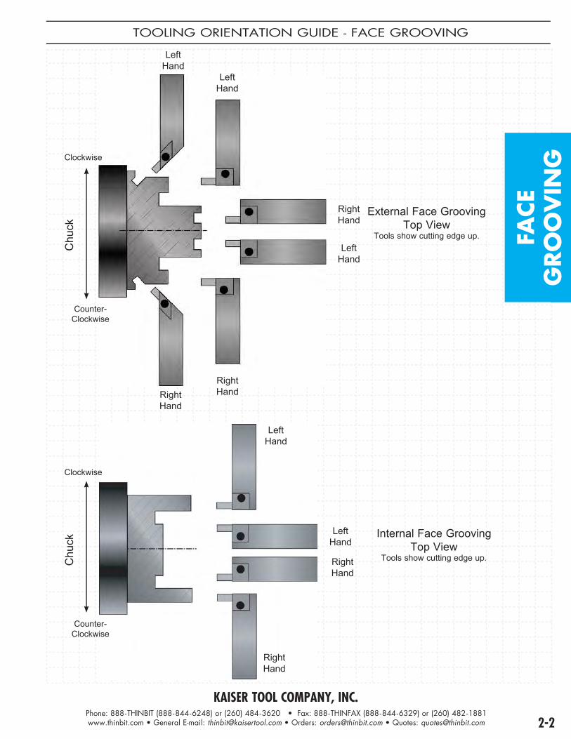
TOOLING ORIENTATION GUIDE - FACE GROOVING
External Face GroovingTop View
Tools show cutting edge up.
LeftHand
Counter-Clockwise
Clockwise
LeftHand
LeftHand
RightHand
RightHand
RightHand
Chu
ck
Internal Face GroovingTop View
Tools show cutting edge up.
Counter-Clockwise
Clockwise
LeftHand
LeftHand
RightHand
RightHand
Chu
ck

KAISER TOOL COMPANY, INC.Phone: 888-THINBIT (888-844-6248) or (260) 484-3620 • Fax: 888-THINFAX (888-844-6329) or (260) 482-1881www.thinbit.com • General E-mail: [email protected] • Orders: [email protected] • Quotes: [email protected]
PRODUCTINFORMATION
• Internal face grooving for diameters .125" and larger.
• Elliptically ground necks for greater strength.
• .004" through .250" in .001" increments available.
• 1/8", 3/16", 1/4", 5/16", 3/8" and 1/2" shanks.
• Sub-micron grain DURA-MAX® 2000 Carbide.• Inserts available with TiN, TiAIN, TiCN and Diamond coating.
Counter-ClockwiseShown
MODIFICATIONSSEE PAGE
8-3 FOR ADDITIONAL
INFORMATION
RADII(TOP VIEW)
LEAD ANGLE(TOP VIEW)
INCLUDED ANGLE(TOP VIEW)
BACK CLEARANCE(TOP VIEW)
CUSTOM BLANK(TOP VIEW)
PG 8-6
TOP RAKE(SIDE VIEW)
CHIP BREAKER(SIDE VIEW)
SIDE CLEARANCE(END VIEW)
TOOLHOLDERSELECTIONS
ADAPTER STYLES
PG 7-2 PG 7-2
TECHNICALSECTIONS
PRODUCT DEMONSTRATION
www.thinbit.com/qr2-3
SPEEDS AND FEEDS
PG 9-15
APPLICATION REFERENCE
PGS 9-3 & 9-4
TROUBLESHOOTING
PG 9-7
®®

KAISER TOOL COMPANY, INC.Phone: 888-THINBIT (888-844-6248) or (260) 484-3620 • Fax: 888-THINFAX (888-844-6329) or (260) 482-1881www.thinbit.com • General E-mail: [email protected] • Orders: [email protected] • Quotes: [email protected] 2-4
INTE
RN
AL
FACE
GRO
OV
ING
INTERNAL FACE GROOVING TOOLS
E
Clockwise Illustrated
FRONT RAKE: Primary 10°
BACK CLEARANCE: 2° ID side
SIDE CLEARANCE: 2° ID side
RADIUS: Sharp corner through full radius available
TOP RAKE: 0°
LEAD ANGLE: 0°
ORDERING INSTRUCTIONS
Complete the ORDER CODE in the table below that represents your selection of groove width and tool dimensions.
EXAMPLE: The ORDER CODE for a 1/4" major diameter, clockwise rotation tool with an .080" groove width,
.125" depth of cut and .750" reach is:FT41C 0 8 0 L
Specify the Groove Width 'A'
SPECIFICATIONS ORDER CODE INFORMATIONMinimum
Bore& Major
Diameter
Groove WidthRange Depth of Cut
ReachintoBore
DURA-MAX® 2000 CarbideSee Page 9-15 for Speeds and Feeds
Add-onsUse 'Order Code' and Add
Overall Length
ToolholderPage 7-2
'C' 'A' 'B' 'E' FullRadiusPage8-3
CornerRadiusPage8-3
CoatingPage 9-6
'D' Use Toolholders Beginning
With ± .001" Counter-Clockwise Clockwise
1/8" .004"-.063" Width DOC .004"-.020" = 3 x 'A' .021"-.063" = .062"
.375" FT21C _ _ _ R FT21C _ _ _ L
add'FR'
add'CR_ _ _'
(indicatesize in.xxx")
TiNadd 'C'
TiCNadd 'D'
TiAlNadd 'E'
Diamondadd 'F'
1.365" + 'B' 'AD'
3/16" .004"-.093" Width DOC .004"-.030" = 3 x 'A' .031"-.093" = .093"
.625" FT31C _ _ _ R FT31C _ _ _ L 1.865" + 'B' 'AD'
1/4" .004"-.125" Width DOC .004"-.041" = 3 x 'A' .042"-.125" = .125"
.750" FT41C _ _ _ R FT41C _ _ _ L 2.365" + 'B' 'AD'
5/16" .004"-.156" Width DOC .004"-.051" = 3 x 'A' .052"-.156" = .156"
1.000" FT51C _ _ _ R FT51C _ _ _ L 2.330" + 'B' 'AD'
3/8" .004"-.187" Width DOC .004"-.061" = 3 x 'A' .062"-.187" = .187"
1.250" FT61C _ _ _ R FT61C _ _ _ L 2.800" + 'B' 'AD'
1/2" .004"-.250" Width DOC .004"-.082" = 3 x 'A' .083"-.250" = .250"
1.750" FT81C _ _ _ R FT81C _ _ _ L 3.240" + 'B' 'AD'
KAISER TOOL COMPANY, INC.Phone: 888-THINBIT (888-844-6248) or (260) 484-3620 • Fax: 888-THINFAX (888-844-6329) or (260) 482-1881www.thinbit.com • General E-mail: [email protected] • Orders: [email protected] • Quotes: [email protected]
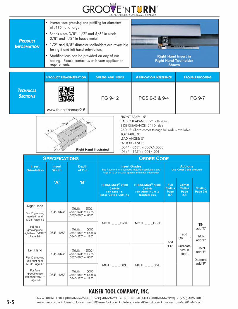
PRODUCT INFORMATION
• Internal face grooving and profiling for diameters of .415" and larger.
• Shank sizes 3/8", 1/2" and 5/8" in steel; 3/8" and 1/2" in heavy metal.
• 1/2" and 5/8" diameter toolholders are reversible for right and left hand orientation.
• Modifications can be provided on any of our tooling. Please contact us with your application requirements.
Right Hand Insert inRight Hand Toolholder
Shown
TECHNICALSECTIONS
PRODUCT DEMONSTRATION
www.thinbit.com/qr2-5
SPEEDS AND FEEDS
PG 9-12
APPLICATION REFERENCE
PGS 9-3 & 9-4
TROUBLESHOOTING
PG 9-7
Right Hand Illustrated
FRONT RAKE: 15° BACK CLEARANCE: 2° both sidesSIDE CLEARANCE: 2° I.D. sideRADIUS: Sharp corner through full radius availableTOP RAKE: 0°LEAD ANGLE: 0°'A' TOLERANCE: .004" - .063": +.0009/-.0000 .064" - .125": +.001/-.001
SPECIFICATIONS ORDER CODEInsert
OrientationInsertWidth
Depthof Cut
Insert GradesSee Page 9-5 for expanded material descriptions and Page 9-10 or 9-12 for speeds and feeds information
Add-onsUse 'Order Code' and Add
'A' 'B' DURA-MAX® 2000 Carbide
For Steel & Interrupted Cutting
DURA-MAX® 5000 Carbide
For Aluminum &Nonferrous
FullRadiusPage8-3
CornerRadiusPage8-3
CoatingPage 9-6
Right Hand
For ID groovinguse left hand
'MGT' Page 1-5
For facegrooving use
right hand 'MGTF'Page 2-6
.004"-.063" Width DOC.004"-.031" = 2 x 'A'.032"-.063" = .063"
MGTI _ _ _D2R MGTI _ _ _D5R
add'FR'
add'CR_ _ _'
(indicatesize in.xxx")
TiNadd 'C'
TiCNadd 'D'
TiAlNadd 'E'
Diamondadd 'F'
.064"-.125" Width DOC.064"-.083" = 1.5 x 'A'.084"-.125" = .125"
Left Hand
For ID groovinguse right hand
'MGT' Page 1-5
For facegrooving use
left hand 'MGTF'Page 2-6
.004"-.063" Width DOC.004"-.031" = 2 x 'A'.032"-.063" = .063"
MGTI _ _ _D2L MGTI _ _ _D5L
.064"-.125" Width DOC.064"-.083" = 1.5 x 'A'.084"-.125" = .125"
U.S. PATENT NOS. 6,722,825 and 6,974,282

KAISER TOOL COMPANY, INC.Phone: 888-THINBIT (888-844-6248) or (260) 484-3620 • Fax: 888-THINFAX (888-844-6329) or (260) 482-1881www.thinbit.com • General E-mail: [email protected] • Orders: [email protected] • Quotes: [email protected] 2-6
I.D
. FA
CE
GRO
OV
ING
I.D. FACE GROOVING TOOLS
�
�
������
����
�� �
�����
���
����
�������
����
�
������
Right Hand Insert and Toolholder Illustrated
Note: • 1/2" and 5/8" toolholders are reversible for right hand or left hand orientation.
• For face grooving: Insert Width Depth of Cut .004"-.031" 2 x width .032"-.063" .063" .064"-.083" 1.5 x width .084"-.125" .125"
ORDERING INSTRUCTIONS
Select the ORDER CODE in the table below that represents your selection of tool specifications.
EXAMPLE: The ORDER CODE for a .530" minimum bore and a 1/2" steel shank is:
MGTF12
SPECIFICATIONS ORDER CODE INFORMATION
Minimum Bore
&Major
Diameter
Orientation &Toolholder Material
ToolholderPackage
Replacement Parts Shank Diameter
Shank Length
InsertsPage 2-5
Includes Shank, Clamp and Hardware
ClampOnly
ScrewOnly
WrenchOnly 'A' 'C' Use Inserts
Beginning With
.415"
Right HandSteel MGTF38R
MGC1 F31 W31
3/8"
5.500" 'MGTI'Use right hand
insertsRight HandHeavy Metal MGTF38RHM 5.485"
Left HandSteel MGTF38L 5.500"
'MGTI'Use left hand insertsLeft Hand
Heavy Metal MGTF38LHM 5.485"
.530"Steel MGTF12
1/2"5.500" 'MGTI'
Use with lefthand inserts for
clockwiseor
with right handinserts for
counter-clockwise
Heavy Metal MGTF12HM 5.485"
.650" Steel MGTF58 5/8" 5.500"

KAISER TOOL COMPANY, INC.Phone: 888-THINBIT (888-844-6248) or (260) 484-3620 • Fax: 888-THINFAX (888-844-6329) or (260) 482-1881www.thinbit.com • General E-mail: [email protected] • Orders: [email protected] • Quotes: [email protected]
PRODUCTINFORMATION
• Internal face grooving for diameters 1.574" and larger with depth of cut to 1".• Shank sizes 3/4", 1", 20mm & 25mm.• Modular tooling system will also accept OD & external face grooving heads. See compatibility guide on Page 9-8. • If square shank is required, see Page 7-14, package styles 'S', 'T', 'U' and 'V'.• Modifications can be provided on any of our tooling. Please contact us with your application requirements. Package 'N'
Shown
TECHNICALSECTIONS
PRODUCT DEMONSTRATION
www.thinbit.com/qr2-7
SPEEDS AND FEEDS
PG 9-12
APPLICATION REFERENCE
PGS 9-3 & 9-4
TROUBLESHOOTING
PG 9-7
PACKAGE STYLE
M - Left Hand Shank, Clockwise
N - Right Hand Shank,
Counter-Clockwise
Top ViewTools show cutting edge up.
Counter-Clockwise
Clockwise
Chu
ck
Note: If square shank is required, see Page 7-14, package styles 'S','T','U' and 'V'.
U.S. PATENT NO. 5,638,728
INSERTSELECTIONS
SEE PAGE 6-1
INSERT STYLES
SHARP CORNER(TOP VIEW)
CORNER RADIUS(TOP VIEW)

KAISER TOOL COMPANY, INC.Phone: 888-THINBIT (888-844-6248) or (260) 484-3620 • Fax: 888-THINFAX (888-844-6329) or (260) 482-1881www.thinbit.com • General E-mail: [email protected] • Orders: [email protected] • Quotes: [email protected] 2-8
I.D
. FA
CE
GRO
OV
ING
I.D. FACE GROOVING TOOLS
ORDERING INSTRUCTIONS
Complete the ORDER CODE in the table below that represents your selection of major diameter.
EXAMPLE: The ORDER CODE for a 3mm insert width, toolholder package style 'N' with a .500" depth of cut,
1" shank and 1.75" major diameter is:DGPN301301 4 5
Specify Major Diameter 'CODE' here
SPECIFICATIONS ORDER CODE
Insert Width
Depth of Cut
Package Style
ToolholderPackage
Includes Shank, Head, Clamp and HardwareInserts Replacement Parts
3/4" Shank7" Long
1" Shank7" Long
20mm Shank178mm (7") Long
25mm Shank178mm (7") Long
Use InsertsBeginning
With Head Head
Hardware
Shank34 = 3/4"01 = 1"
20 = 20mm25 = 25mm
Clamp ClampHardware
2mm (.078")
13mm (1/2")
M DGPM201334 _ _ DGPM201301 _ _ DGPM201320 _ _ DGPM201325 _ _ 'DGI2'
(Page 6-1)
DGH52013 _ _
Screw:2 eachS7552
Wrench:W4025
DGS_ _ZL DGC52013
Screw:S6552
Wrench:W4025
N DGPN201334 _ _ DGPN201301 _ _ DGPN201320 _ _ DGPN201325 _ _ DGH62013 _ _ DGS_ _ZR DGC62013
3mm (.118")
13mm (1/2")
M DGPM301334 _ _ DGPM301301 _ _ DGPM301320 _ _ DGPM301325 _ _ 'DGI3'
(Page 6-1)
DGH53013 _ _ DGS_ _ZL DGC53013
N DGPN301334 _ _ DGPN301301 _ _ DGPN301320 _ _ DGPN301325 _ _ DGH63013 _ _ DGS_ _ZR DGC63013
4mm (.157")
13mm (1/2")
M DGPM401334 _ _ DGPM401301 _ _ DGPM401320 _ _ DGPM401325 _ _
'DGI4'
(Page 6-1)
DGH54013 _ _ DGS_ _ZL DGC54013
N DGPN401334 _ _ DGPN401301 _ _ DGPN401320 _ _ DGPN401325 _ _ DGH64013 _ _ DGS_ _ZR DGC64013
20mm (3/4")
M DGPM402034 _ _ DGPM402001 _ _ DGPM402020 _ _ DGPM402025 _ _ DGH54020 _ _ DGS_ _ZL DGC54020
N DGPN402034 _ _ DGPN402001 _ _ DGPN402020 _ _ DGPN402025 _ _ DGH64020 _ _ DGS_ _ZR DGC64020
5mm (.197")
13mm (1/2")
M DGPM501334 _ _ DGPM501301 _ _ DGPM501320 _ _ DGPM501325 _ _
'DGI5'
(Page 6-1)
DGH55013 _ _ DGS_ _ZL DGC55013
N DGPN501334 _ _ DGPN501301 _ _ DGPN501320 _ _ DGPN501325 _ _ DGH65013 _ _ DGS_ _ZR DGC65013
25mm (1")
M DGPM502534 _ _ DGPM502501 _ _ DGPM502520 _ _ DGPM502525 _ _ DGH55025 _ _ DGS_ _ZL DGC55025
N DGPN502534 _ _ DGPN502501 _ _ DGPN502520 _ _ DGPN502525 _ _ DGH65025 _ _ DGS_ _ZR DGC65025
6mm (.236")
13mm (1/2")
M DGPM601334 _ _ DGPM601301 _ _ DGPM601320 _ _ DGPM601325 _ _
'DGI6'
(Page 6-1)
DGH56013 _ _ DGS_ _ZL DGC56013
N DGPN601334 _ _ DGPN601301 _ _ DGPN601320 _ _ DGPN601325 _ _ DGH66013 _ _ DGS_ _ZR DGC66013
25mm (1")
M DGPM602534 _ _ DGPM602501 _ _ DGPM602520 _ _ DGPM602525 _ _ DGH56025 _ _ DGS_ _ZL DGC56025
N DGPN602534 _ _ DGPN602501 _ _ DGPN602520 _ _ DGPN602525 _ _ DGH66025 _ _ DGS_ _ZR DGC66025
Major Diameter Range Code1.574"-1.968" (40-50mm) 451.968"-2.362" (50-60mm) 562.362"-2.952" (60-75mm) 672.952"-3.937" (75-100mm) 71
3.937"-5.905" (100-150mm) 115.905"-11.811" (150-300mm) 13
11.811"- ∞ (300mm-∞) 30
Note:As long as first plunge is made within major diameter range and each following plunge overlaps, groove width can be increased toward or away from center of part.

KAISER TOOL COMPANY, INC.Phone: 888-THINBIT (888-844-6248) or (260) 484-3620 • Fax: 888-THINFAX (888-844-6329) or (260) 482-1881www.thinbit.com • General E-mail: [email protected] • Orders: [email protected] • Quotes: [email protected]
PRODUCT INFORMATION
• Face grooving for major diameters .300", .750", 1.250", 3" and greater.• Face grooving with a central hub, recessed or flat face.• .004" - .150" in .001" increments available.• Sub-micron grain DURA-MAX® 2000 and 5000 Carbides.• Inserts available with TiN, TiAIN, TiCN and Diamond coating.
MODIFICATIONSSEE PAGES
8-2 & 8-3 FOR ADDITIONAL
INFORMATION
RADII(TOP VIEW)
DEPTH OF CUT(TOP VIEW)
SIZING(TOP VIEW)
BACK CLEARANCE(TOP VIEW)
LEAD ANGLE(TOP VIEW)
TOP RAKE(SIDE VIEW)
CHIP BREAKER(SIDE VIEW)
SIDE CLEARANCE(END VIEW)
TOOLHOLDERSELECTIONS
CNC, SWISS, CONVENTIONAL STYLE
®
MADE
IN
U.S.A.
THINBIT® KAISER TOOL
3/4" GROOVE ‘
PG 7-3 PG 7-4
ROUND STYLE
����
����
��
�
������
�����
�����
����
�����
����
� ��
PG 7-7
� � � � � �
�
PG 7-8
45º STYLE
PG 7-11
SWISS FACE STYLE
PG 7-6
TECHNICALSECTIONS
PRODUCT DEMONSTRATION
www.thinbit.com/qr2-9
SPEEDS AND FEEDS
PG 9-12
APPLICATION REFERENCE
PGS 9-3 & 9-4
TROUBLESHOOTING
PG 9-7
INSERTSU.S. PATENT NOS. 6,688,816 and 6,824,333
Right Hand,Counter-Clockwise Insert in Right Hand,
Straight Toolholder Shown
Left Hand,Counter-Clockwise
Insert in Left Hand, Straight
ToolholderShown

KAISER TOOL COMPANY, INC.Phone: 888-THINBIT (888-844-6248) or (260) 484-3620 • Fax: 888-THINFAX (888-844-6329) or (260) 482-1881www.thinbit.com • General E-mail: [email protected] • Orders: [email protected] • Quotes: [email protected] 2-10
ORDERING INSTRUCTIONS EXAMPLE:
Sample ORDER CODE for a left hand/counter-clockwise, .100" wide insert in DURA-MAX® 2000, with a .750" major diameter and no corner radius is:
LGTF 1 0 0 D27504 Specify the Insert Width 'A'
* 3.000" Major Diameter Excludes .004" - .019" Insert Width Due to Side Clearance
Cut with a LH CCW Insert Cut with a RH CCW Insert
SPECIFICATIONS ORDER CODE INFO.
Insert Orientation
Insert Width Depth of Cut Major
DiameterInsert Grades
See Page 9-5 for expanded material descriptions and Page 9-12 for Speeds and Feeds information
Add-onsUse 'Order Code' and Add
ToolholderCatalog
Section 7
'A' 'B' Can be usedon
any diameterequal to or
greater thanlisted
DURA-MAX® 2000 Carbide
For Steel &Interrupted Cutting
DURA-MAX® 5000 Carbide
For Aluminum &Nonferrous
FullRadiusPage8-3
CornerRadiusPage8-3
CoatingPage 9-6
Use Toolholders Beginning
With'L'± .001"
Left Hand/ Counter-
Clockwise.004" - .150"
Width D.O.C..004"-.033" = 3 x 'A'.034"-.039" = .100".040"-.100" = 2.5 x 'A'.101"-.150" = .250"
.300" LGTF _ _ _ D23004 LGTF _ _ _ D53004
add'FR'
add'CR_ _ _'
(indicatesize in.xxx")
TiNadd 'C'
TiCNadd 'D'
TiAlNadd 'E'
Diamondadd 'F'
For shouldercutting
useleft hand
straight holderor
right hand 90º holder
.750" LGTF _ _ _ D27504 LGTF _ _ _ D57504
1.250" LGTF _ _ _ D212504 LGTF _ _ _ D512504
* 3.000" LGT _ _ _ D2L LGT _ _ _ D5L
Right Hand/ Counter-
Clockwise.004" - .150"
Width D.O.C..004"-.033" = 3 x 'A'.034"-.039" = .100".040"-.100" = 2.5 x 'A'.101"-.150" = .250"
300" LGTF _ _ _ D23002 LGTF _ _ _ D53002
Use right hand
or left hand straight holder
orright hand 90º
holder
.750" LGTF _ _ _ D27502 LGTF _ _ _ D57502
1.250" LGTF _ _ _ D212502 LGTF _ _ _ D512502
* 3.000" LGT _ _ _ D2R LGT _ _ _ D5R
INSE
RTS
FA
CE
GRO
OV
ING
FACE GROOVING INSERTS
.145"
.240"
.145"
.240"
THINBIT®
LGTF100D27504
.820"
AB Left Hand,
Counter-ClockwiseIllustrated
.145"
.240"
.145"
.240"
THINBIT®
LGTF100D27502
.820".820"
B
A D=.325"
FRONT RAKE: Primary 10° honed, Secondary 15°BACK CLEARANCE: 2-1/2° both sides
SIDE CLEARANCE: .004" - .019" - 0° ID side.020" - .150" - 5° ID side
RADIUS: Sharp corner through full radius availableTOP RAKE: 0°
LEAD ANGLE: 0°NOTE: Capable of grooving along a shoulder
Right Hand,Counter-Clockwise
Illustrated
C
A
B
C
A
DB

KAISER TOOL COMPANY, INC.Phone: 888-THINBIT (888-844-6248) or (260) 484-3620 • Fax: 888-THINFAX (888-844-6329) or (260) 482-1881www.thinbit.com • General E-mail: [email protected] • Orders: [email protected] • Quotes: [email protected]
• For Dovetail O-Ring face grooving and OD/ID grooving.• Groove Widths .030", .050", .060", .070", .080", .090", .100", .125" & .150".• Major diameters from .300".• Sub-micron grain DURA-MAX® 2000 and 5000 Carbides.• Inserts available with TiN, TiCN, TiAIN or Diamond film coating.
PRODUCTINFORMATION
MODIFICATIONSSEE PAGES
8-2 & 8-3 FOR ADDITIONAL
INFORMATION
RADII(TOP VIEW)
DEPTH OF CUT(TOP VIEW)
SIZING(TOP VIEW)
BACK CLEARANCE(TOP VIEW)
LEAD ANGLE(TOP VIEW)
TOP RAKE(SIDE VIEW)
CHIP BREAKER(SIDE VIEW)
SIDE CLEARANCE(END VIEW)
TOOLHOLDERSELECTIONS
CNC, SWISS, CONVENTIONAL STYLE
®
MADE
IN
U.S.A.
THINBIT® KAISER TOOL
3/4" GROOVE ‘
PG 7-3 PG 7-4
ROUND STYLE
����
����
��
�
������
�����
�����
����
�����
����
� ��
PG 7-7
� � � � � �
�
PG 7-8
45º STYLE
PG 7-11
SWISS FACE STYLE
PG 7-6
TECHNICALSECTIONS
PRODUCT DEMONSTRATION
www.thinbit.com/qr2-11
SPEEDS AND FEEDS
PG 9-12
APPLICATION REFERENCE
PGS 9-3 & 9-4
TROUBLESHOOTING
PG 9-7
INSERTSU.S. PATENT NOS. 6,688,816 and 6,824,333
RH 90° Toolholder
Style 5 dovetail
insert
RH 90° Toolholder
Style 6 dovetail
insert

KAISER TOOL COMPANY, INC.Phone: 888-THINBIT (888-844-6248) or (260) 484-3620 • Fax: 888-THINFAX (888-844-6329) or (260) 482-1881www.thinbit.com • General E-mail: [email protected] • Orders: [email protected] • Quotes: [email protected] 2-12
DO
VE
TAIL
FACE
GRO
OV
ING
DOVETAIL O-RING FACE GROOVING INSERTS
"
"
"
Style 6 Shown
FRONT RAKE: Primary 10° honed, Secondary 15°
BACK CLEARANCE: 24° one side
SIDE CLEARANCE: Depends on major diameter
RADIUS: On 24° side only
TOP RAKE: 0°
LEAD ANGLE: 0°
Notes:• For best performance, form undercut by profiling. • If using on either an ID Bore or OD Shaft contact us for assistance.• Half dovetail form requires a radius on both corners.
ORDERING INSTRUCTIONS
Select the ORDER CODE in the table below that represents your selection of groove width and insert grade.EXAMPLE:
The ORDER CODE for a left hand/counter-clockwise, .100" wide OD side insert in DURA-MAX® 2000, with a .300" major diameter and a .030" corner radius is:
LGDT100D23006CR030
SPECIFICATIONS ORDER CODE INFO.
Insert Orientation& Radius
Insert Width
Depthof
CutRadius
Insert GradesSee Page 9-5 for expanded material descriptionsand Page 9-12 for Speeds and Feeds information
Add-onsUse 'Order Code' and
Add
ToolholderCatalog
Section 7
'A' 'B' DURA-MAX® 2000 Carbide
For Steel &Interrupted Cutting
DURA-MAX® 5000 CarbideFor Aluminum &
Nonferrous CoatingPage 9-6
Use Toolholders Beginning
With ± .001" Style 5(ID Tool)
Style 6(OD Tool)
Style 5(ID Tool)
Style 6(OD Tool)
Left Hand/ Counter-
Clockwise
.030" .030" .015" LGDT030D2___5CR015 LGDT030D2___6CR015 LGDT030D5___5CR015 LGDT030D5___6CR015
TiNadd 'C'
TiCNadd 'D'
TiAlNadd 'E'
Diamondadd 'F'
'L'
.050" .070" .015" LGDT050D2___5CR015 LGDT050D2___6CR015 LGDT050D5___5CR015 LGDT050D5___6CR015
.060" .070" .015" LGDT060D2___5CR015 LGDT060D2___6CR015 LGDT060D5___5CR015 LGDT060D5___6CR015
.070" .100" .015" LGDT070D2___5CR015 LGDT070D2___6CR015 LGDT070D5___5CR015 LGDT070D5___6CR015
.080" .100" .015" LGDT080D2___5CR015 LGDT080D2___6CR015 LGDT080D5___5CR015 LGDT080D5___6CR015
.090" .115" .015" LGDT090D2___5CR015 LGDT090D2___6CR015 LGDT090D5___5CR015 LGDT090D5___6CR015
.100" .125" .015" LGDT100D2___5CR015 LGDT100D2___6CR015 LGDT100D5___5CR015 LGDT100D5___6CR015
.100" .125" .030" LGDT100D2___5CR030 LGDT100D2___6CR030 LGDT100D5___5CR030 LGDT100D5___6CR030
.125" .190" .030" LGDT125D2___5CR030 LGDT125D2___6CR030 LGDT125D5___5CR030 LGDT125D5___6CR030
.150" .200" .030" LGDT150D2___5CR030 LGDT150D2___6CR030 LGDT150D5___5CR030 LGDT150D5___6CR030
Major Diameter Code
.300" 300 .500" 500 1.000" 10001.500" 15002.000" 20003.000" 3000
Major Diameter Code
Style 5 (ID Tool)
Style 6 (OD Tool)Style 6 (OD Tool) Style 5 (ID Tool)
Note: both styles 5 & 6 are necessary to create a complete dovetail groove.
Dovetail InsertStyles

KAISER TOOL COMPANY, INC.Phone: 888-THINBIT (888-844-6248) or (260) 484-3620 • Fax: 888-THINFAX (888-844-6329) or (260) 482-1881www.thinbit.com • General E-mail: [email protected] • Orders: [email protected] • Quotes: [email protected]
PRODUCTINFORMATION
• For Static O-Ring Face Grooving.• Groove widths .086", .103", .122", .125" & .138".• 7° included angle.• Major diameters starting from .300".• Sub-micron grain DURA-MAX® 2000 and 5000 Carbides.• Inserts available with TiN, TiCN, TiAIN or Diamond film coating.
Insert and Right Hand, 90° Toolholder
Shown
MODIFICATIONSSEE PAGES
8-2 & 8-3 FOR ADDITIONAL
INFORMATION
TOOLHOLDERSELECTIONS
CNC, SWISS, CONVENTIONAL STYLE
®
MADE
IN
U.S.A.
THINBIT® KAISER TOOL
3/4" GROOVE ‘
PG 7-3 PG 7-4
ROUND STYLE
����
����
��
�
������
�����
�����
����
�����
����
� ��
PG 7-7
� � � � � �
�
PG 7-8
45º STYLE
PG 7-12
SWISS FACE STYLE
PG 7-6
TECHNICALSECTIONS
PRODUCT DEMONSTRATION
www.thinbit.com/qr2-13
SPEEDS AND FEEDS
PG 9-12
APPLICATION REFERENCE
PGS 9-3 & 9-4
TROUBLESHOOTING
PG 9-7
RADII(TOP VIEW)
LEAD ANGLE(TOP VIEW)
DEPTH OF CUT(TOP VIEW)
TOP RAKE(SIDE VIEW)
SIZING(TOP VIEW)
CHIP BREAKER(SIDE VIEW)
BACK CLEARANCE(TOP VIEW)
SIDE CLEARANCE(END VIEW)
INSERTSU.S. PATENT NOS. 6,688,816 and 6,824,333

KAISER TOOL COMPANY, INC.Phone: 888-THINBIT (888-844-6248) or (260) 484-3620 • Fax: 888-THINFAX (888-844-6329) or (260) 482-1881www.thinbit.com • General E-mail: [email protected] • Orders: [email protected] • Quotes: [email protected] 2-14
STA
TIC O
-RIN
GFA
CE
GRO
OV
ING
STATIC O-RING FACE GROOVING INSERTS
.145"
.240".820"
A B
7OT H I N
B I T®
L G O R F 1 3 8 D 2
7 5 0 8 C R 0 1 0
FRONT RAKE: Primary 10° honed, Secondary 15°
BACK CLEARANCE: 7° included angle
SIDE CLEARANCE: 5° both sides
RADIUS: .010" or .020"
TOP RAKE: 0°
LEAD ANGLE: 0°
DEPTH OF CUT: .170" or .250"
ORDERING INSTRUCTIONS
Select the ORDER CODE in the table below that represents your selection of groove width and insert grade.
EXAMPLE: The ORDER CODE for a counter-clockwise, .138" wide insert in DURA-MAX® 2000,
with a .750" major diameter and a .010" corner radius is:LGORF138D27508CR010
SPECIFICATIONS ORDER CODE INFO.
Insert Orientation &
Radius
Insert Width
Depth of Cut
Major Diameter
Insert GradesSee Page 9-5 for expanded material descriptions and
Page 9-12 for Speeds and Feeds information
Add-onsUse 'Order
Code' and Add
ToolholderCatalogSection 7
'A' 'B' Can be used on any
diameter equal to or
greater than listed
DURA-MAX® 2000 CarbideFor Steel &
Interrupted Cutting
DURA-MAX® 5000 CarbideFor Aluminum &
Non-ferrous
CoatingPage 9-6
Use Toolholders
Beginning With ± .001"
Counter-Clockwise;
.010"Corner Radius
.086" .250".300" LGORF086D23008CR010 LGORF086D53008CR010
TiN add 'C'
TiCN add 'D'
TiAlN add 'E'
Diamond add 'F'
'L'
Use left hand straight holder
orright hand 90°
holder
.750" LGORF086D27508CR010 LGORF086D57508CR010
.103" .250".300" LGORF103D23008CR010 LGORF103D53008CR010
.750" LGORF103D27508CR010 LGORF103D57508CR010
.122" .250".300" LGORF122D23008CR010 LGORF122D53008CR010
.750" LGORF122D27508CR010 LGORF122D57508CR010
.138" .170".300" LGORF138D23008CR010 LGORF138D53008CR010
.750" LGORF138D27508CR010 LGORF138D57508CR010
Counter-Clockwise;
.020"Corner Radius
.125" .250".300" LGORF125D23008CR020 LGORF125D53008CR020
.750" LGORF125D27508CR020 LGORF125D57508CR020

KAISER TOOL COMPANY, INC.Phone: 888-THINBIT (888-844-6248) or (260) 484-3620 • Fax: 888-THINFAX (888-844-6329) or (260) 482-1881www.thinbit.com • General E-mail: [email protected] • Orders: [email protected] • Quotes: [email protected]
PRODUCTINFORMATION
• External face grooving with depth of cut to 1".• Shank sizes 3/4", 1", 16mm, 20mm and 25mm in straight and 90º orientations.• Modular tooling system will also accept OD & internal face grooving heads. See compatibility guide on Page 9-8.• If round shanks are required, see Page 7-13, package styles 'O' and 'P'. • Modifications can be provided on any of our tooling. Please contact us with your application requirements.• Major diameter starting from .787".
Package 'D'Shown
TECHNICALSECTIONS
PRODUCT DEMONSTRATION
www.thinbit.com/qr2-15
SPEEDS AND FEEDS
PG 9-12
APPLICATION REFERENCE
PGS 9-3 & 9-4
TROUBLESHOOTING
PG 9-7
PACKAGE STYLE
A - Left Hand, 90º Shank, Clockwise
B - Right Hand, Straight Shank, Clockwise
D - Right Hand, 90º Shank,
Counter-Clockwise
C - Left Hand, Straight Shank,
Counter-Clockwise
Top ViewTools show cutting edge up.
Counter-Clockwise
Clockwise
Chu
ck
Note: If round shanks are required, see Page 7-13, package styles 'O' and 'P'.
3/4", 1" and Metric ShanksSelect the ORDER CODE in the table at right that represents your selection of major diameter.
EXAMPLE: The ORDER CODE for a 3mm insert width,
toolholder package style 'C' with a .500" depth of cut, 1" shank and 1" major diameter is:DGPC3013 0 1 2 3
Specify the 'SHANK SIZE' and MAJOR DIAMETER 'CODE'
ORDERING INSTRUCTIONS
INSERTSELECTIONS
SEE PAGE 6-1
INSERT STYLES
SHARP CORNER(TOP VIEW)
CORNER RADIUS(TOP VIEW)
U.S. PATENT NO. 5,638,728
®

KAISER TOOL COMPANY, INC.Phone: 888-THINBIT (888-844-6248) or (260) 484-3620 • Fax: 888-THINFAX (888-844-6329) or (260) 482-1881www.thinbit.com • General E-mail: [email protected] • Orders: [email protected] • Quotes: [email protected] 2-16
DEE
PG
RO
OV
EFA
CE
GRO
OV
ING
FACE GROOVING TOOLS
Major DiameterRange
InsertWidth Code Insert
StyleMajor Diameter
RangeInsertWidth Code Insert
Style
.787"- .885" (20-22.5mm)2mm 02 DGI
1.377"-1.574" (35-40mm)2mm 50 DGI
3 & 4mm 02 DGMI 3, 4, 5 & 6mm 34 DGI
.885"- .984" (22.5-25mm)2mm 25 DGI 1.574"-1.968" (40-50mm)
All
45 DGI3 & 4mm 25 DGMI 1.968"-2.362" (50-60mm) 56 DGI
.984"-1.082" (25-27.5mm)2mm 57 DGI 2.362"-2.952" (60-75mm) 67 DGI
3, 4, 5 & 6mm 23 DGI 2.952"-3.937" (75-100mm) 71 DGI
1.082"-1.181" (27.5-30mm)2mm 70 DGI 3.937"-5.905" (100-150mm) 11 DGI
3, 4, 5 & 6mm 23 DGI 5.905"-11.811" (150-300mm) 13 DGI
1.181"-1.377" (30-35mm)2mm 05 DGI 11.811"- ∞ (300mm-∞) 30 DGI
3, 4, 5 & 6mm 34 DGI
Note:As long as first plunge is made within major diameter range and each following plunge overlaps, groove width can be increased toward or away from center of part.
ShankMajor Diameter Code
SPECIFICATIONS ORDER CODEInsert Width
Depth of Cut
Package Style
ToolholderPackage
Includes Shank, Head, Clamp and Hardware
Inserts Replacement Parts
Section 6
Use Inserts Beginning With
Head Head Hardware
Shank34 = 3/4"
01 = 1"16 = 16mm20 = 20mm25 = 25mm
Clamp ClampHardwareSee Page
2-153/4" Shank
3/4"x3/4"x5"
1" Shank
1"x1"x5"
Metric Shanks16 = 16x16x125mm20 = 20x1"x125mm25 = 25x1"x125mm
2mm (.078")
13mm (1/2")
A DGPA201334_ _ DGPA201301_ _ DGPA2013 _ _ _ _'DGI2'
(Page 6-1)
DGH32013_ _
Screw:2 eachS7552
Wrench:W4025
DGS_ _YLDGC12013
Screw:S6552
Wrench:W4025
B DGPB201334_ _ DGPB201301_ _ DGPB2013 _ _ _ _ DGS_ _XR
C DGPC201334_ _ DGPC201301_ _ DGPC2013 _ _ _ _DGH42013_ _
DGS_ _XLDGC22013
D DGPD201334_ _ DGPD201301_ _ DGPD2013 _ _ _ _ DGS_ _YR
3mm (.118")
13mm (1/2")
A DGPA301334_ _ DGPA301301_ _ DGPA3013 _ _ _ _ Use 'DGMI3' for major diameter
codes'02'&'25'
'DGI3' for all others
(Page 6-1)
DGH33013_ _DGS_ _YL
DGC13013B DGPB301334_ _ DGPB301301_ _ DGPB3013 _ _ _ _ DGS_ _XR
C DGPC301334_ _ DGPC301301_ _ DGPC3013 _ _ _ _DGH43013_ _
DGS_ _XLDGC23013
D DGPD301334_ _ DGPD301301_ _ DGPD3013 _ _ _ _ DGS_ _YR
4mm (.157")
13mm (1/2")
A DGPA401334_ _ DGPA401301_ _ DGPA4013 _ _ _ _
Use 'DGMI4' for major diameter
codes'02'&'25'
'DGI4' for all others
(Page 6-1)
DGH34013_ _DGS_ _YL
DGC14013B DGPB401334_ _ DGPB401301_ _ DGPB4013 _ _ _ _ DGS_ _XR
C DGPC401334_ _ DGPC401301_ _ DGPC4013 _ _ _ _DGH44013_ _
DGS_ _XLDGC24013
D DGPD401334_ _ DGPD401301_ _ DGPD4013 _ _ _ _ DGS_ _YR
20mm (3/4")
A DGPA402034_ _ DGPA402001_ _ DGPA4020 _ _ _ _DGH34020_ _
DGS_ _YLDGC14020
B DGPB402034_ _ DGPB402001_ _ DGPB4020 _ _ _ _ DGS_ _XR
C DGPC402034_ _ DGPC402001_ _ DGPC4020 _ _ _ _DGH44020_ _
DGS_ _XLDGC24020
D DGPD402034_ _ DGPD402001_ _ DGPD4020 _ _ _ _ DGS_ _YR
5mm (.197")
13mm (1/2")
A DGPA501334_ _ DGPA501301_ _ DGPA5013 _ _ _ _
'DGI5'
(Page 6-1)
DGH35013_ _DGS_ _YL
DGC15013B DGPB501334_ _ DGPB501301_ _ DGPB5013 _ _ _ _ DGS_ _XR
C DGPC501334_ _ DGPC501301_ _ DGPC5013 _ _ _ _DGH45013_ _
DGS_ _XLDGC25013
D DGPD501334_ _ DGPD501301_ _ DGPD5013 _ _ _ _ DGS_ _YR
25mm (1")
A DGPA502534_ _ DGPA502501_ _ DGPA5025 _ _ _ _DGH35025_ _
DGS_ _YLDGC15025
B DGPB502534_ _ DGPB502501_ _ DGPB5025 _ _ _ _ DGS_ _XR
C DGPC502534_ _ DGPC502501_ _ DGPC5025 _ _ _ _DGH45025_ _
DGS_ _XLDGC25025
D DGPD502534_ _ DGPD502501_ _ DGPD5025 _ _ _ _ DGS_ _YR
6mm (.236")
13mm (1/2")
A DGPA601334_ _ DGPA601301_ _ DGPA6013 _ _ _ _
'DGI6'
(Page 6-1)
DGH36013_ _DGS_ _YL
DGC16013B DGPB601334_ _ DGPB601301_ _ DGPB6013 _ _ _ _ DGS_ _XR
C DGPC601334_ _ DGPC601301_ _ DGPC6013 _ _ _ _DGH46013_ _
DGS_ _XLDGC26013
D DGPD601334_ _ DGPD601301_ _ DGPD6013 _ _ _ _ DGS_ _YR
25mm (1")
A DGPA602534_ _ DGPA602501_ _ DGPA6025 _ _ _ _DGH36025_ _
DGS_ _YLDGC16025
B DGPB602534_ _ DGPB602501_ _ DGPB6025 _ _ _ _ DGS_ _XR
C DGPC602534_ _ DGPC602501_ _ DGPC6025 _ _ _ _DGH46025_ _
DGS_ _XLDGC26025
D DGPD602534_ _ DGPD602501_ _ DGPD6025 _ _ _ _ DGS_ _YR

KAISER TOOL COMPANY, INC.Phone: 888-THINBIT (888-844-6248) or (260) 484-3620 • Fax: 888-THINFAX (888-844-6329) or (260) 482-1881www.thinbit.com • General E-mail: [email protected] • Orders: [email protected] • Quotes: [email protected]
Scan this code for additional information
www.thinbit.com/qr3-1
BO
RIN
G PRODUCT SELECTION GUIDE - BORING, PROFILING & TURNING
PAGE 3-3
• Finish boring• For internal diameters of .073" and larger• Solid carbide shanks in 1/8", 3/16", 1/4", 5/16", 3/8" and 1/2" diameter
PAGE 3-5
• Profi ling & Reverse Profi ling• For internal diameters of .125" and larger• Solid carbide shanks in 1/8", 3/16", 1/4", 5/16", 3/8" and 1/2" diameter
PAGE 3-7to
3-10
• Rough boring using Trigon inserts• PAGE 3-8: .210" Min. Bore; MBE (WCGT) style• PAGE 3-9: .270" Min. Bore; MBF (WCGT) style• PAGE 3-10: .410" Min. Bore; MBG (WCGT) style
PAGE 3-11
to3-18
• Finish boring• PAGE 3-12: .165" Min. Bore; MBZ style• PAGE 3-13: .180" Min. Bore; MBA (CD) style• PAGE 3-15: .270" Min. Bore; MBB (TD) style• PAGE 3-17: .430" Min. Bore; MBC (TP) style
OVER 100,000 TOOLS IN STOCK FORGROOVING • THREADING • PARTING • BORING
TURNING • FACE GROOVINGSPECIALS • FORM TOOLS

KAISER TOOL COMPANY, INC.Phone: 888-THINBIT (888-844-6248) or (260) 484-3620 • Fax: 888-THINFAX (888-844-6329) or (260) 482-1881www.thinbit.com • General E-mail: [email protected] • Orders: [email protected] • Quotes: [email protected] 3-2
BO
RIN
G
TOOLING ORIENTATION GUIDE - BORING, PROFILING & TURNING
Boring ApplicationsTop View
Tools show cutting edge up.
Counter-Clockwise
Clockwise
LeftHand
RightHand
Chu
ck
'K' ANGLE
Other Manufacturers' Bars0° Radial Rake
MINI-BORE® bars are designed to cut above center with a negative cutting rake or 'K' angle. As the diameter of the bar increases the 'K' angle decreases. Flats are provided to ensure speedy and proper set-up.
This unique design provides critical advantages over other manufacturers' small diameter bars: • Up to 25% greater cross-sectional area under the cutting edge which increases the strength and rigidity of the pocket. • Increased screw thread engagement to reduce thread stripping and increase the holding power. • Better surface finishes due to better chip control and flow.
®

KAISER TOOL COMPANY, INC.Phone: 888-THINBIT (888-844-6248) or (260) 484-3620 • Fax: 888-THINFAX (888-844-6329) or (260) 482-1881www.thinbit.com • General E-mail: [email protected] • Orders: [email protected] • Quotes: [email protected]
PRODUCT INFORMATION
• For boring diameters .073" and larger.
• 1/8", 3/16", 1/4", 5/16", 3/8" and 1/2" shank.
• Elliptically ground necks for greater strength.
• Round necks to fit into small diameters.
• Sub-micron grain DURA-MAX® 2000 Carbide.• Tools available with TiN, TiAIN, TiCN and Diamond coating. Right Hand
Shown
MODIFICATIONSSEE PAGE
8-3 FOR ADDITIONAL
INFORMATION
CUSTOM BLANK(T V )
PG 8-6
RADII(T V )
LEAD ANGLE(T V )
BACK CLEARANCE(T V )
TOP RAKE(S V )
CHIP BREAKER(S V )
SIDE CLEARANCE(E V )
TOOLHOLDERSELECTIONS
ADAPTER STYLES
�����������
PG 7-2
����
����
��
PG 7-2
TECHNICALSECTIONS
PRODUCT DEMONSTRATION
www.thinbit.com/qr3-3
SPEEDS AND FEEDS
PG 9-15
APPLICATION REFERENCE
PG 9-4
TROUBLESHOOTING
PG 9-7
®®

KAISER TOOL COMPANY, INC.Phone: 888-THINBIT (888-844-6248) or (260) 484-3620 • Fax: 888-THINFAX (888-844-6329) or (260) 482-1881www.thinbit.com • General E-mail: [email protected] • Orders: [email protected] • Quotes: [email protected] 3-4
TOO
LSBO
RIN
G
BORING TOOLS
BT41CR
Right Hand Illustrated
FRONT RAKE: Primary 21°
BACK CLEARANCE: 3° Lead side
SIDE CLEARANCE: 7° Lead side
LEAD ANGLE: 6°
RADIUS: None
TOP RAKE: 0°
NOTE: Tool designed for feeding into bore only.
ORDERING INSTRUCTIONS
Select the ORDER CODE in the table below that represents your selection of tool dimensions.EXAMPLE:
The ORDER CODE for a .250" minimum bore, right hand tool with a .875" tool reach and .062" projection is:BT41CR
Specifi cations Order Code Information
Minimum Bore
Tool Reach Projection
DURA-MAX® 2000 CarbideSee Page 9-15 for Speeds and Feeds
CoatingsSee Page 9-6 for expanded coating
descriptions
Shank Diameter
Overall Length
ToolholderPage 7-2
'C' 'E' 'F' Use uncoated part number and add coating code 'B' 'D'
Use Toolholders Beginning With
Minimum +.000"/- .010" Right Hand Left Hand TiN TiCN TiAlN Diamond
.073"Round Neck
.500" .010" BT21AR BT21AL
add 'C'
add 'D'
add 'E'
add 'F'
1/8" 1.500" 'AD'
.125" .500" .031" BT21CR BT21CL
.187" .750" .047" BT31CR BT31CL 3/16" 2.000" 'AD'
.250" .875" .062" BT41CR BT41CL 1/4" 2.500" 'AD'
.312" 1.156" .078" BT51CR BT51CL 5/16" 2.500" 'AD'
.375" 1.437" .125" BT61CR BT61CL 3/8" 3.000" 'AD'
.500" 2.000" .167" BT81CR BT81CL 1/2" 3.500" 'AD'

KAISER TOOL COMPANY, INC.Phone: 888-THINBIT (888-844-6248) or (260) 484-3620 • Fax: 888-THINFAX (888-844-6329) or (260) 482-1881www.thinbit.com • General E-mail: [email protected] • Orders: [email protected] • Quotes: [email protected]
PRODUCT INFORMATION
• For profiling diameters .125" and larger.• 1/8", 3/16", 1/4", 5/16", 3/8" and 1/2" shank.• Elliptically ground necks for greater strength.• Sub-micron grain DURA-MAX® 2000 Carbide.• Tools available with TiN, TiAIN, TiCN and Diamond coating.
MODIFICATIONSSEE PAGE
8-3 FOR ADDITIONAL
INFORMATION
CUSTOM BLANK(TOP VIEW)
PG 8-6
RADII(TOP VIEW)
LEAD ANGLE(TOP VIEW)
BACK CLEARANCE(TOP VIEW)
TOP RAKE(SIDE VIEW)
CHIP BREAKER(SIDE VIEW)
SIDE CLEARANCE(END VIEW)
TOOLHOLDERSELECTIONS
ADAPTER STYLES
�����������
PG 7-2
����
����
��
PG 7-2
TECHNICALSECTIONS
PRODUCT DEMONSTRATION
www.thinbit.com/qr3-5
SPEEDS AND FEEDS
PG 9-15
APPLICATION REFERENCE
PG 9-4
TROUBLESHOOTING
PG 9-7
Select the ORDER CODE in the table on the next page that represents your selection of tool dimensions.EXAMPLE:
The ORDER CODE for a .375" minimum bore, right hand tool with a 1.350" tool reach and .125" projection is:PT61CR
ORDERING INSTRUCTIONS
Right HandProfiling
Tool Shown
Right HandReverseProfiling
Tool Shown
®®

KAISER TOOL COMPANY, INC.Phone: 888-THINBIT (888-844-6248) or (260) 484-3620 • Fax: 888-THINFAX (888-844-6329) or (260) 482-1881www.thinbit.com • General E-mail: [email protected] • Orders: [email protected] • Quotes: [email protected] 3-6
PRO
FILI
NG
PROFILING & REVERSE PROFILING TOOLS
PT61CRTHINBIT®
5.0O
30.0OG
Profiling Tools
Right Hand Illustrated
FRONT RAKE: Primary 21°SIDE CLEARANCE: 5° Lead sideBACK CLEARANCE: 5° Lead sideBACK CLEARANCE: 30° Trailing sideNOTE: Tool designed for feeding into bore only.
SPECIFICATIONS ORDER CODE INFORMATION
Minimum Bore
Tool Reach
NoseRadius Projection DURA-MAX®
2000 CarbideSee Page 9-15 for Speeds
and Feeds
CoatingsSee Page 9-6 for expanded coating
descriptions
Shank Diameter
Overall Length
ToolholderPage 7-2
'C' 'E' 'G' 'F' Use uncoated part number and add coating code 'B' 'D' Use Toolholders
Beginning With Minimum Minimum Right Hand Left Hand TiN TiCN TiAlN Diamond
.125" .425" .007" .052" PT21BR PT21BL
add 'C'
add 'D'
add 'E'
add 'F'
1/8" 1.500" 'AD'
.187" .705" .010" .083" PT31BR PT31BL 3/16" 2.000" 'AD'
.250" .840" .010" .115" PT41BR PT41BL 1/4" 2.500" 'AD'
.312" 1.115" .015" .146" PT51BR PT51BL 5/16" 2.500" 'AD'
.375" 1.350" .015" .115" PT61CR PT61CL 3/8" 3.000" 'AD'
.500" 1.870" .015" .157" PT81CR PT81CL 1/2" 3.500" 'AD'
FRONT RAKE: Primary 21°SIDE CLEARANCE: 10° Lead sideBACK CLEARANCE: 30° Lead sideBACK CLEARANCE: 5° Trailing side NOTE: Tool designed for feeding out of bore only.
RT61CRTHINBIT®
30.0O
5.0O
G Right Hand Illustrated
SPECIFICATIONS ORDER CODE INFORMATION
Minimum Bore
Tool Reach
NoseRadius Projection DURA-MAX®
2000 CarbideSee Page 9-15 for Speeds
and Feeds
CoatingsSee Page 9-6 for expanded coating
descriptions
Shank Diameter
Overall Length
ToolholderPage 7-2
'C' 'E' 'G' 'F' Use uncoated part number and add coating code 'B' 'D' Use
Toolholders Beginning
With Minimum Minimum Right Hand Left Hand TiN TiCN TiAlN Diamond
.125" .375" .007" .052" RT21BR RT21BL
add 'C'
add 'D'
add 'E'
add 'F'
1/8" 1.500" 'AD'
.187" .625" .010" .083" RT31BR RT31BL 3/16" 2.000" 'AD'
.250" .750" .010" .115" RT41BR RT41BL 1/4" 2.500" 'AD'
.312" 1.000" .015" .146" RT51BR RT51BL 5/16" 2.500" 'AD'
.375" 1.250" .015" .115" RT61CR RT61CL 3/8" 3.000" 'AD'
.500" 1.750" .015" .157" RT81CR RT81CL 1/2" 3.500" 'AD'
Reverse Profiling Tools

KAISER TOOL COMPANY, INC.Phone: 888-THINBIT (888-844-6248) or (260) 484-3620 • Fax: 888-THINFAX (888-844-6329) or (260) 482-1881www.thinbit.com • General E-mail: [email protected] • Orders: [email protected] • Quotes: [email protected]
PRODUCT INFORMATION
• Boring with .210" minimum bore diameter.• 'K' angle increases strength in insert pocket by increasing the cross-sectional area below the insert.• Boring bars for WCGT insert style.• Variety of diameters made from Steel, Heavy Metal and Carbide.• Bars and inserts are compatible with other ANSI standard bars and inserts. Call for cross-overs.• Sub-micron grain DURA-MAX® 4000 and 5000 Carbide.• Tools available with TiN, TiAIN, TiCN and Diamond coating.• Modifi cations can be provided on any of our tooling. Please contact us with your application requirements.
Right HandShown
TOOLHOLDERSELECTIONS
WCGT STYLE - MBE SERIES
PG 3-8.210" Min Bore
WCGT STYLE - MBF SERIES
PG 3-9.270" Min Bore
WCGT STYLE - MBG SERIES
PG 3-10.410" Min Bore
�������������
PG 7-2��
�����
��
��
PG 7-2
INSERTSELECTIONS
WCGT STYLE - MBE SERIES
WCGT 1.21 PG 3-8
WCGT STYLE - MBF SERIES
WCGT 1.51.5 PG 3-9
WCGT STYLE - MBG SERIES
WCGT 21.5 PG 3-10
TECHNICALSECTIONS
PRODUCT DEMONSTRATION
www.thinbit.com/qr3-7
SPEEDS AND FEEDS
PG 9-14
APPLICATION REFERENCE
PG 9-4
TROUBLESHOOTING
PG 9-7
ADAPTER STYLES

KAISER TOOL COMPANY, INC.Phone: 888-THINBIT (888-844-6248) or (260) 484-3620 • Fax: 888-THINFAX (888-844-6329) or (260) 482-1881www.thinbit.com • General E-mail: [email protected] • Orders: [email protected] • Quotes: [email protected] 3-8
MBE
TRIG
ON
BO
RIN
G
TO ORDER WCGT STYLE - MBE SERIES BORING BARS
Select the ORDER CODE in the table below that represents your selection of tool specifications.EXAMPLE:
The ORDER CODE for a .270" minimum bore, right hand, heavy metal shank with a 3º lead angle is:MBEH132527R
�
�
�
�
TO ORDER WCGT STYLE - MBE SERIES INSERTS
Select the ORDER CODE in the table below that represents your selection of insert specifications.EXAMPLE:
The ORDER CODE for a DURA-MAX® 4000 insert with .008" radius and TiN coating is:MBEIW08D4C
WCGT StyleMBE Series
Use toolholders beginning with 'MBE'
SPECIFICATIONS ORDER CODE
InsertMaterial
CornerRadius
CoatingSee Page 9-5 for expanded material description and
Page 9-14 for speeds and feeds
Uncoated TiN TiCNNon-stock
TiAlN Non-stock
DURA-MAX®
4000 carbideFor Steel &
Interrupted Cutting
.004" MBEIW04D4U MBEIW04D4C MBEIW04D4D MBEIW04D4E
.008" MBEIW08D4U MBEIW08D4C MBEIW08D4D MBEIW08D4E
.015" MBEIW15D4U MBEIW15D4C MBEIW15D4D MBEIW15D4E
DURA-MAX®
5000 carbideFor Aluminum &
Nonferrous
.004" MBEIW04D5U MBEIW04D5C MBEIW04D5D MBEIW04D5E
.008" MBEIW08D5U MBEIW08D5C MBEIW08D5D MBEIW08D5E
.015" MBEIW15D5U MBEIW15D5C MBEIW15D5D MBEIW15D5E
TOOL SPECIFICATIONS ORDER CODEMinimum
Bore Material Bar Diameter Length Lead Angle
'K'Angle Boring Bar Replacement Parts
'B' Extension Ratios:Steel: 4 x øHeavy Metal: 6 x øCarbide: 8 x ø
'A' 'D' 'C' 'K'Includes Screw and
Wrench.156" I.C. With .008" radius insert
see page 3-2
Screw Wrench
.210"
Steel .188" 3.500" 3° 17° MBES131821R F15 W11
Right HandBars
Heavy Metal .188" 3.976" 3° 17° MBEH131821R F15 W11
Carbide .188" 4.474" 3° 17° MBEC131821R F15 W11
.220"Steel .188" 3.500" 0° 17° MBES101822R F15 W11
Use inserts beginning with 'MBEIW' and
ANSI 'WCGT 1.21'inserts
Heavy Metal .188" 3.976" 0° 17° MBEH101822R F15 W11
.270"
Steel .250" 4.000"0° 12° MBES102527R F15 W11
3° 12° MBES132527R F15 W11
Heavy Metal .250" 3.976"
0° 12° MBEH102527R F15 W11
3° 12° MBEH132527R F15 W11
Left HandBars
Use inserts beginning with 'MBEIW' and
ANSI 'WCGT 1.21'inserts
.210"Steel .188" 3.500" 3° 17° MBES131821L F15 W11
Heavy Metal .188" 3.976" 3° 17° MBEH131821L F15 W11
.270"Steel .250" 4.000" 3° 12° MBES132527L F15 W11
Heavy Metal .250" 3.976" 3° 12° MBEH132527L F15 W11

KAISER TOOL COMPANY, INC.Phone: 888-THINBIT (888-844-6248) or (260) 484-3620 • Fax: 888-THINFAX (888-844-6329) or (260) 482-1881www.thinbit.com • General E-mail: [email protected] • Orders: [email protected] • Quotes: [email protected]
TO ORDER WCGT STYLE - MBF SERIES BORING BARS
Select the ORDER CODE in the table below that represents your selection of tool specifications.EXAMPLE:
The ORDER CODE for a .330" minimum bore, right hand, heavy metal shank with a 0º lead angle is:MBFH103133R
�
�
�
�
TOOL SPECIFICATIONS ORDER CODEMinimum
Bore Material Bar Diameter Length Lead Angle
'K'Angle Boring Bar Replacement Parts
'B' Extension Ratios:Steel: 4 x ø
Heavy Metal: 6 x øCarbide: 8 x ø
'A' 'D' 'C' 'K'Includes Screw and
Wrench.187" I.C. With .008" radius insert
See Page 3-2
Screw Wrench
.270"
Steel .250" 4.000"0° 15° MBFS102527R F15 W11
Right HandBars
3° 15° MBFS132527R F15 W11
HeavyMetal .250" 3.976"
0° 15° MBFH102527R F15 W11
Use inserts beginning with
'MBFIW' andANSI 'WCGT 1.51.5'
inserts
3° 15° MBFH132527R F15 W11
Carbide .250" 6.488" 3° 15° MBFC132527R F15 W11
.330"
Steel .312" 4.000"0° 15° MBFS103133R F15 W11
3° 15° MBFS133133R F15 W11
HeavyMetal .312" 5.500"
0° 15° MBFH103133R F15 W11
3° 15° MBFH133133R F15 W11
Left HandBars
Use inserts beginning with
'MBFIW' andANSI 'WCGT 1.51.5'
inserts
.270"Steel .250" 4.000" 3° 15° MBFS132527L F15 W11
Heavy Metal .250" 3.976" 3° 15° MBFH132527L F15 W11
.330"Steel .312" 4.000" 3° 15° MBFS133133L F15 W11
Heavy Metal .312" 5.500" 3° 15° MBFH133133L F15 W11
TO ORDER WCGT STYLE - MBF SERIES INSERTS
Select the ORDER CODE in the table below that represents your selection of insert specifications.EXAMPLE:
The ORDER CODE for a DURA-MAX® 4000 insert with .008" radius and TiN coating is:MBFIW08D4C
WCGT StyleMBF Series
Use toolholders beginning with 'MBF'
SPECIFICATIONS ORDER CODE
InsertMaterial
CornerRadius
CoatingSee Page 9-5 for expanded material description and Page 9-14 for Speeds and Feeds
Uncoated TiN TiCNNon-stock
TiAlN Non-stock
DURA-MAX®
4000 carbideFor Steel &
Interrupted Cutting
.004" MBFIW04D4U MBFIW04D4C MBFIW04D4D MBFIW04D4E
.008" MBFIW08D4U MBFIW08D4C MBFIW08D4D MBFIW08D4E
.015" MBFIW15D4U MBFIW15D4C MBFIW15D4D MBFIW15D4E
DURA-MAX®
5000 carbideFor Aluminum &
Nonferrous
.004" MBFIW04D5U MBFIW04D5C MBFIW04D5D MBFIW04D5E
.008" MBFIW08D5U MBFIW08D5C MBFIW08D5D MBFIW08D5E
.015" MBFIW15D5U MBFIW15D5C MBFIW15D5D MBFIW15D5E

KAISER TOOL COMPANY, INC.Phone: 888-THINBIT (888-844-6248) or (260) 484-3620 • Fax: 888-THINFAX (888-844-6329) or (260) 482-1881www.thinbit.com • General E-mail: [email protected] • Orders: [email protected] • Quotes: [email protected] 3-10
TO ORDER WCGT STYLE - MBG SERIES BORING BARS
Select the ORDER CODE in the table below that represents your selection of tool specifications.EXAMPLE:
The ORDER CODE for a .410" minimum bore, right hand, heavy metal shank with a 3º lead angle is:MBGH133741R
�
�
�
�
TOOL SPECIFICATIONS ORDER CODEMinimum
Bore Material Bar Diameter Length Lead Angle
'K'Angle Boring Bar Replacement Parts
'B' Extension Ratios:Steel: 4 x ø
Heavy Metal: 6 x øCarbide: 8 x ø
'A' 'D' 'C' 'K'Includes Screw and
Wrench.250" I.C. With .008" radius insert
See Page 3-2
Screw Wrench
.410"
Steel .375" 5.500"0° 8° MBGS103741R F26 W26
Right HandBars
3° 8° MBGS133741R F26 W26
HeavyMetal .375" 5.500"
0° 8° MBGH103741R F26 W26
Use inserts beginning with 'MBGIW' and
ANSI 'WCGT 21.5'inserts
3° 8° MBGH133741R F26 W26
Carbide .375" 6.777" 3° 8° MBGC133741R F26 W26
.530"
Steel .500" 5.500"0° 8° MBGS105053R F26 W26
3° 8° MBGS135053R F26 W26
HeavyMetal .500" 5.500"
0° 8° MBGH105053R F26 W26
3° 8° MBGH135053R F26 W26
Left HandBars
Use inserts beginning with 'MBGIW' and
ANSI 'WCGT 21.5'inserts
.410"Steel .375" 5.500" 3° 8° MBGS133741L F26 W26
Heavy Metal .375" 5.500" 3° 8° MBGH133741L F26 W26
.530"Steel .500" 5.500" 3° 8° MBGS135053L F26 W26
Heavy Metal .500" 5.500" 3° 8° MBGH135053L F26 W26
TO ORDER WCGT STYLE - MBG SERIES INSERTS Select the ORDER CODE in the table below that represents your selection of insert specifications.
EXAMPLE: The ORDER CODE for a DURA-MAX® 4000 insert with .008" radius and TiN coating is:
MBGIW08D4C
MBF
& M
BG
TRIG
ON
BO
RIN
GWCGT StyleMBG Series
Use toolholders beginning with
'MBG'
SPECIFICATIONS ORDER CODE
InsertMaterial
CornerRadius
CoatingSee Page 9-5 for expanded material description and Page 9-14 for Speeds and Feeds
Uncoated TiN TiCNNon-stock
TiAlN Non-stock
DURA-MAX®
4000 carbideFor Steel &
Interrupted Cutting
.004" MBGIW04D4U MBGIW04D4C MBGIW04D4D MBGIW04D4E
.008" MBGIW08D4U MBGIW08D4C MBGIW08D4D MBGIW08D4E
.015" MBGIW15D4U MBGIW15D4C MBGIW15D4D MBGIW15D4E
DURA-MAX®
5000 carbideFor Aluminum &
Nonferrous
.004" MBGIW04D5U MBGIW04D5C MBGIW04D5D MBGIW04D5E
.008" MBGIW08D5U MBGIW08D5C MBGIW08D5D MBGIW08D5E
.015" MBGIW15D5U MBGIW15D5C MBGIW15D5D MBGIW15D5E

KAISER TOOL COMPANY, INC.Phone: 888-THINBIT (888-844-6248) or (260) 484-3620 • Fax: 888-THINFAX (888-844-6329) or (260) 482-1881www.thinbit.com • General E-mail: [email protected] • Orders: [email protected] • Quotes: [email protected]
PRODUCT INFORMATION
• Boring with .165" minimum bore diameter.• 'K' angle increases strength in insert pocket by increasing the cross-sectional area below the insert.• Boring bars for CD, TD and TP insert styles.• Variety of diameters made from Steel, Heavy Metal and Carbide.• Sub-micron grain DURA-MAX® 3000, 4000 and 5000 Carbides.• CBN tipped DURA-MAX® 8000.• PCD tipped DURA-MAX® 9000.• Inserts available with TiN, TiAIN, TiCN and Diamond coating.• Bars and inserts are completely compatible with other ANSI standard bars and inserts. Call for cross-overs. • Modifi cations can be provided on any of our tooling. Please contact us with your application requirements.
Right HandShown
TOOLHOLDERSELECTIONS
CD STYLE - MBZ SERIES
PG 3-12.165" Min. Bore
CD STYLE - MBA SERIES
PG 3-13.180" Min. Bore
TD STYLE - MBB SERIES
PG 3-15.270" Min. Bore
TP STYLE - MBC SERIES
PG 3-17.430" Min. Bore
ADAPTER STYLES
���������
PG 7-2��
�����
��
PG 7-2
INSERTSELECTIONS
CD STYLE - MBA SERIES
PG 3-14
TD STYLE - MBB SERIES
PG 3-16
TP STYLE - MBC SERIES
PG 3-18
TECHNICALSECTIONS
PRODUCT DEMONSTRATION
www.thinbit.com/qr3-11
SPEEDS AND FEEDS
PG 9-15
APPLICATION REFERENCE
PG 9-4
TROUBLESHOOTING
PG 9-7
®®

KAISER TOOL COMPANY, INC.Phone: 888-THINBIT (888-844-6248) or (260) 484-3620 • Fax: 888-THINFAX (888-844-6329) or (260) 482-1881www.thinbit.com • General E-mail: [email protected] • Orders: [email protected] • Quotes: [email protected] 3-12
MBZ
BA
RS
& IN
SERTS
BO
RIN
G
Select the ORDER CODE in the table below that represents your selection of tool specifications.EXAMPLE:
The ORDER CODE for a .165" minimum bore, right hand, steel, .187" shank is:MBZS171816R
�
�
�
��
TO ORDER CD STYLE - MBZ SERIES BORING BARS
.140
TO ORDER CDCD STYLE - MBZ SERIES INSERTS
Select the ORDER CODE in the table below that represents your selection of insert specifications.EXAMPLE:
The ORDER CODE for a DURA-MAX® 5000 insert with .007" radius and TiN coating is:MBZIZ07D5C
TOOL SPECIFICATIONS ORDER CODEMinimum
Bore Material Bar Diameter Length Neck Length
Lead Angle
'K'Angle Boring Bar Replacement Parts
'B' Extension Ratios:
Steel: 4 x ø Carbide: 8 x ø
'A' 'D' 'E' 'C' 'K'Includes Screw
and Wrench.140" I.C. With .007" radius insert Screw Wrench
Right HandBars
Use inserts beginning with
'MBZIZ'
0.165"
Steel .187" 2.500" .580" 7° 17° MBZS171816R
F11 W11
Carbide .156" 4.477" 1.500" 7° 17° MBZC171516R
MBZ SeriesUse toolholders
beginning with 'MBZ'
SPECIFICATIONS ORDER CODE
InsertMaterial
CornerRadius
CoatingSee Page 9-5 for expanded material description and Page 9-15 for speeds and feeds
Uncoated TiN TiCNNon-stock
TiAlN Non-stock
Diamond Non-stock
DURA-MAX®4000 carbide
For Steel &Interrupted Cutting
.002" MBZIZ02D4U MBZIZ02D4C MBZIZ02D4D MBZIZ02D4E MBZIZ02D4F
.007" MBZIZ07D4U MBZIZ07D4C MBZIZ07D4D MBZIZ07D4E MBZIZ07D4F
.015" MBZIZ15D4U MBZIZ15D4C MBZIZ15D4D MBZIZ15D4E MBZIZ15D4F
DURA-MAX®5000 carbideFor Aluminum &
Nonferrous
.002" MBZIZ02D5U MBZIZ02D5C MBZIZ02D5D MBZIZ02D5E MBZIZ02D5F
.007" MBZIZ07D5U MBZIZ07D5C MBZIZ07D5D MBZIZ07D5E MBZIZ07D5F
.015" MBZIZ15D5U MBZIZ15D5C MBZIZ15D5D MBZIZ15D5E MBZIZ15D5F

KAISER TOOL COMPANY, INC.Phone: 888-THINBIT (888-844-6248) or (260) 484-3620 • Fax: 888-THINFAX (888-844-6329) or (260) 482-1881www.thinbit.com • General E-mail: [email protected] • Orders: [email protected] • Quotes: [email protected]
TO ORDER CD STYLE - MBA SERIES BORING BARS
Select the ORDER CODE in the table below that represents your selection of tool specifications.EXAMPLE:
The ORDER CODE for a .205" minimum bore, right hand, steel, .187" shank is:MBAS151820R
TOOL SPECIFICATIONS ORDER CODEMinimum
Bore Material Bar Diameter Length Lead Angle
'K'Angle Boring Bar Replacement Parts
'B'Extension Ratios:
Steel: 4 x øHeavy Metal: 6 x ø
Carbide: 8 x ø
'F' 'A' 'E' 'D' 'C' 'K'
.156" I.C. With .007" radius insert Neck Shank Neck Overall
See Page 3-2
Includes Screw and Wrench Screw Wrench
.180"
Steel.164" .187" .520" 2.500" 7º 17º MBAS171818R
F11 W11
.164" .375" .500" 2.500" 7º 17º MBAS373718R050
Heavy Metal
.156" --- 3.976" 7º 17º MBAH171518R
.164" .500" .750" 3.000" 7º 17º MBAH375018R075
Carbide .156" --- 4.477" 7º 17º MBAC171518R
.205"Steel
.187" --- 3.500" 5º 17º MBAS151820R
F15 W11.180" .500" .500" 3.000" 5º 17º MBAS355020R050Heavy Metal .187" --- 3.976" 5º 17º MBAH151820R
Right HandBars
.210"Steel
.187" --- 3.500" 0º 17º MBAS101821R
F15 W11.187" .375" 1.000" 3.000" 5º 17º MBAS353721R100
Heavy Metal .187" --- 3.976" 0º 17º MBAH101821R
Use inserts beginning with
'MBAIW', 'MBAIZ',
left hand 'MBAIG'inserts and
most ANSI 'CD'standard inserts
.220"
Steel .197" .375" .500" 2.500" 0º 17º MBAS303722R050
F15 W11Heavy Metal
.187" --- 3.976" 5º 17º MBAH151822R
.187" .500" 1.125" 3.977" 5º 17º MBAH355022R112
Carbide .187" --- 4.477" 5º 17º MBAC151822R
.230" Steel .187" --- 3.500" 5º 17º MBAS151823R F15 W11
.270" Steel .250" --- 4.000" 0º 12º MBAS102527R F15 W11
.280"
Steel.250" --- 4.000" 5º 12º MBAS152528R
F15 W11.250" .375" 1.250" 3.000" 5º 12º MBAS353728R125
Heavy Metal .250" --- 3.976" 5º 12º MBAH152528R
Carbide .250" --- 6.504" 5º 12º MBAC152528R
.350" Heavy Metal .313" --- 5.500" 5º 8º MBAH153135R F15 W11
Left HandBars
Use inserts beginning
with 'MBAIW','MBAIZ',
right hand 'MBAIG'inserts and
most ANSI 'CD'standard inserts
.180"Steel .164" .187" .520" 2.500" 7º 17º MBAS171818L
F11 W11Heavy Metal .156" --- 3.976" 7º 17º MBAH171518L
.205" Steel .180" .500" .500" 3.000" 5º 17º MBAS355020L050
F15 W11.230" Steel .187" --- 3.500" 5º 17º MBAS151823L
.280" Steel .250" --- 4.000" 5º 12º MBAS152528L
������ �
�
�
�
��
�
�
�
�
�
�� �� ��� �
�

KAISER TOOL COMPANY, INC.Phone: 888-THINBIT (888-844-6248) or (260) 484-3620 • Fax: 888-THINFAX (888-844-6329) or (260) 482-1881www.thinbit.com • General E-mail: [email protected] • Orders: [email protected] • Quotes: [email protected] 3-14
MBA
BA
RS
& IN
SERTS
BO
RIN
G
TO ORDER CD STYLE - MBA SERIES INSERTS
Select the ORDER CODE in the table below that represents your selection of insert specifications.EXAMPLE:
The ORDER CODE for a molded chipbreaker, DURA-MAX® 4000 insert with .007" radius and TiN coating is:MBAIW07D4C
CD StyleMBA Series
Use toolholders beginning with 'MBA'
SPECIFICATIONS ORDER CODE
InsertMaterial
CornerRadius
CoatingSee Page 9-5 for expanded material descriptions and Page 9-15 for Speeds and Feeds
Uncoated TiN TiCNNon-stock
TiAlNNon-stock
DiamondNon-stock
Flat top DURA-MAX®
4000 CarbideFor Steel &
Interrupted Cutting
.002" MBAIZ02D4U MBAIZ02D4C MBAIZ02D4D MBAIZ02D4E MBAIZ02D4F
.007" MBAIZ07D4U MBAIZ07D4C MBAIZ07D4D MBAIZ07D4E MBAIZ07D4F
.015" MBAIZ15D4U MBAIZ15D4C MBAIZ15D4D MBAIZ15D4E MBAIZ15D4F
DURA-MAX®
5000 CarbideFor Aluminum &
Nonferrous
.002" MBAIZ02D5U MBAIZ02D5C MBAIZ02D5D MBAIZ02D5E MBAIZ02D5F
.007" MBAIZ07D5U MBAIZ07D5C MBAIZ07D5D MBAIZ07D5E MBAIZ07D5F
.015" MBAIZ15D5U MBAIZ15D5C MBAIZ15D5D MBAIZ15D5E MBAIZ15D5F
DURA-MAX®
8000 CBNFor Hardened
Materials
.002" MBAIZ02D8
.007" MBAIZ07D8
.015" MBAIZ15D8
DURA-MAX®
9000 PCDFor AbrasiveNonferrous
.002" MBAIZ02D9
.007" MBAIZ07D9
CDCD Style .015" MBAIZ15D9
Molded Chipbreaker DURA-MAX®
4000 CarbideFor Steel &
Interrupted Cutting
.007" MBAIW07D4U MBAIW07D4C MBAIW07D4D MBAIW07D4E MBAIW07D4F
.015" MBAIW15D4U MBAIW15D4C MBAIW15D4D MBAIW15D4E MBAIW15D4F
DURA-MAX®
5000 CarbideFor Aluminum &
Nonferrous
.007" MBAIW07D5U MBAIW07D5C MBAIW07D5D MBAIW07D5E MBAIW07D5F
CDCH Style .015" MBAIW15D5U MBAIW15D5C MBAIW15D5D MBAIW15D5E MBAIW15D5F
Ground ChipbreakerRight Hand for Left Hand Bars
DURA-MAX®
4000 CarbideFor Steel &
Interrupted Cutting
.002" MBAIG02D4UR MBAIG02D4CR MBAIG02D4DR MBAIG02D4ER MBAIG02D4FR
.007" MBAIG07D4UR MBAIG07D4CR MBAIG07D4DR MBAIG07D4ER MBAIG07D4FR
.015" MBAIG15D4UR MBAIG15D4CR MBAIG15D4DR MBAIG15D4ER MBAIG15D4FR
DURA-MAX®
5000 CarbideFor Aluminum &
Nonferrous
.002" MBAIG02D5UR MBAIG02D5CR MBAIG02D5DR MBAIG02D5ER MBAIG02D5FR
.007" MBAIG07D5UR MBAIG07D5CR MBAIG07D5DR MBAIG07D5ER MBAIG07D5FR
CDCG Style .015" MBAIG15D5UR MBAIG15D5CR MBAIG15D5DR MBAIG15D5ER MBAIG15D5FR
Ground ChipbreakerLeft Hand for Right
Hand BarsDURA-MAX®
4000 CarbideFor Steel &
Interrupted Cutting
.002" MBAIG02D4UL MBAIG02D4CL MBAIG02D4DL MBAIG02D4EL MBAIG02D4FL
.007" MBAIG07D4UL MBAIG07D4CL MBAIG07D4DL MBAIG07D4EL MBAIG07D4FL
.015" MBAIG15D4UL MBAIG15D4CL MBAIG15D4DL MBAIG15D4EL MBAIG15D4FL
DURA-MAX®
5000 CarbideFor Aluminum &
Nonferrous
.002" MBAIG02D5UL MBAIG02D5CL MBAIG02D5DL MBAIG02D5EL MBAIG02D5FL
.007" MBAIG07D5UL MBAIG07D5CL MBAIG07D5DL MBAIG07D5EL MBAIG07D5FL
CDCG Style .015" MBAIG15D5UL MBAIG15D5CL MBAIG15D5DL MBAIG15D5EL MBAIG15D5FL
���������� ��
����� ���
����������

KAISER TOOL COMPANY, INC.Phone: 888-THINBIT (888-844-6248) or (260) 484-3620 • Fax: 888-THINFAX (888-844-6329) or (260) 482-1881www.thinbit.com • General E-mail: [email protected] • Orders: [email protected] • Quotes: [email protected]
TO ORDER TD STYLE - MBB SERIES BORING BARS
Select the ORDER CODE in the table below that represents your selection of tool specifications.EXAMPLE:
The ORDER CODE for a .300" minimum bore, right hand, heavy metal, .500" shank step bar is:MBBH355030R150
B A
C
D
STANDARD BARS
K
STEP BARS
D
AB
C
E
F
K
TOOL SPECIFICATIONS ORDER CODEMinimum
Bore Material Bar Diameter Length Lead Angle
'K'Angle Boring Bar Replacement Parts
'B'Extension Ratios:
Steel: 4 x øHeavy Metal: 6 x ø
Carbide: 8 x ø
'F' 'A' 'E' 'D' 'C' 'K'
.160" I.C. With .007" radius insert Neck Shank Neck Overall
See Page 3-2
Includes Screw and Wrench Screw Wrench
.270"
Steel
.187" --- 3.500" 0° 17° MBBS101827R
F22 W11
.187" --- 3.500" 5° 17° MBBS151827R
.187" .500" 1.000" 3.000" 5° 17° MBBS355027R100
HeavyMetal
.187" --- 3.976" 0° 17° MBBH101827R
.187" --- 3.976" 5° 17° MBBH151827R
.187" .500" 1.125" 3.965" 5° 17° MBBH355027R112
Carbide .187" --- 4.487" 5° 17° MBBC151827R
Right HandBars
.300"
Steel
.250" --- 4.000" 0° 12° MBBS102530R
F22 W11
.250" --- 4.000" 5° 12° MBBS152530R
Use inserts beginning with
'MBBIW', 'MBBIZ',
left hand 'MBBIG'inserts and
most ANSI 'TD'standard inserts
.250" .500" 1.250" 3.000" 5° 12° MBBS355030R125
.250" .625" 1.250" 4.000" 5° 12° MBBS356230R125
HeavyMetal
.250" --- 3.976" 0° 12° MBBH102530R
.250" --- 3.976" 5° 12° MBBH152530R
.250" .500" 1.500" 3.981" 5° 12° MBBH355030R150
Carbide .250" --- 6.488" 5° 12° MBBC152530R
.350"
Steel
.313" --- 4.000" 0° 8° MBBS103135R
F22 W11
.313" --- 4.000" 5° 8° MBBS153135R
.313" .500" 1.000" 3.000" 5° 8° MBBS355035R100
HeavyMetal
.313" --- 5.500" 0° 8° MBBH103135R
.313" --- 5.500" 5° 8° MBBH153135R
.313" .500" 1.500" 3.981" 5° 8° MBBH355035R150
Carbide .313" --- 6.483" 5° 8° MBBC153135R
Left HandBars
Use inserts beginning with
'MBBIW','MBBIZ',
right hand 'MBBIG'inserts and
most ANSI 'TD'standard inserts
.270" Steel .187" --- 3.500" 5° 17° MBBS151827L
F22 W11
.300" Steel .250" --- 4.000" 5° 12° MBBS152530L
.350"
Steel .313" --- 4.000" 5° 8° MBBS153135L
HeavyMetal .313" --- 5.500" 5° 8° MBBH153135L

KAISER TOOL COMPANY, INC.Phone: 888-THINBIT (888-844-6248) or (260) 484-3620 • Fax: 888-THINFAX (888-844-6329) or (260) 482-1881www.thinbit.com • General E-mail: [email protected] • Orders: [email protected] • Quotes: [email protected] 3-16
MBB B
ARS
& IN
SERTS
BO
RIN
G
TO ORDER TD STYLE - MBB SERIES INSERTS
Select the ORDER CODE in the table below that represents your selection of insert specifications.EXAMPLE:
The ORDER CODE for a molded chipbreaker, DURA-MAX® 4000 insert with .007" radius and TiN coating is:MBBIW07D4C
TD StyleMBB Series
Use toolholders beginning with 'MBB'
SPECIFICATIONS ORDER CODE
InsertMaterial
CornerRadius
CoatingSee Page 9-5 for expanded material descriptions and Page 9-15 for Speeds and Feeds
Uncoated TiN TiCNNon-stock
TiAlNNon-stock
DiamondNon-stock
Flat top DURA-MAX®
3000/4000
Carbide*For Steel &
Interrupted Cutting
.002" MBBIZ02D3U MBBIZ02D3C MBBIZ02D3D MBBIZ02D3E MBBIZ02D3F
.007" MBBIZ07D3U MBBIZ07D3C MBBIZ07D3D MBBIZ07D3E MBBIZ07D3F
.015" MBBIZ15D3U MBBIZ15D3C MBBIZ15D3D MBBIZ15D3E MBBIZ15D3F
.031" MBBIZ31D3U MBBIZ31D3C MBBIZ31D3D MBBIZ31D3E MBBIZ31D3F
DURA-MAX®
5000 CarbideFor Aluminum &
Nonferrous
.002" MBBIZ02D5U MBBIZ02D5C MBBIZ02D5D MBBIZ02D5E MBBIZ02D5F
.007" MBBIZ07D5U MBBIZ07D5C MBBIZ07D5D MBBIZ07D5E MBBIZ07D5F
.015" MBBIZ15D5U MBBIZ15D5C MBBIZ15D5D MBBIZ15D5E MBBIZ15D5F
.031" MBBIZ31D5U MBBIZ31D5C MBBIZ31D5D MBBIZ31D5E MBBIZ31D5F
DURA-MAX®
8000 CBNFor Hardened
Materials
.002" MBBIZ02D8
.007" MBBIZ07D8
.015" MBBIZ15D8
.031" MBBIZ31D8
DURA-MAX®
9000 PCDFor AbrasiveNonferrous
.002" MBBIZ02D9
.007" MBBIZ07D9
.015" MBBIZ15D9
TDAB Style .031" MBBIZ31D9
Molded ChipbreakerDURA-MAX®
4000 CarbideFor Steel &
Interrupted Cutting
.007" MBBIW07D4U MBBIW07D4C MBBIW07D4D MBBIW07D4E MBBIW07D4F
.015" MBBIW15D4U MBBIW15D4C MBBIW15D4D MBBIW15D4E MBBIW15D4F
DURA-MAX®
5000 CarbideFor Aluminum &
Nonferrous
.007" MBBIW07D5U MBBIW07D5C MBBIW07D5D MBBIW07D5E MBBIW07D5F
TDCH Style.015" MBBIW15D5U MBBIW15D5C MBBIW15D5D MBBIW15D5E MBBIW15D5F
Ground ChipbreakerRight Hand for Left Hand Bars
DURA-MAX®
3000 CarbideFor Steel &
Interrupted Cutting
.002" MBBIG02D3UR MBBIG02D3CR MBBIG02D3DR MBBIG02D3ER MBBIG02D3FR
.007" MBBIG07D3UR MBBIG07D3CR MBBIG07D3DR MBBIG07D3ER MBBIG07D3FR
.015" MBBIG15D3UR MBBIG15D3CR MBBIG15D3DR MBBIG15D3ER MBBIG15D3FR
.031" MBBIG31D3UR MBBIG31D3CR MBBIG31D3DR MBBIG31D3ER MBBIG31D3FR
DURA-MAX®
5000 CarbideFor Aluminum &
Nonferrous
.002" MBBIG02D5UR MBBIG02D5CR MBBIG02D5DR MBBIG02D5ER MBBIG02D5FR
.007" MBBIG07D5UR MBBIG07D5CR MBBIG07D5DR MBBIG07D5ER MBBIG07D5FR
.015" MBBIG15D5UR MBBIG15D5CR MBBIG15D5DR MBBIG15D5ER MBBIG15D5FR
TDCG Style .031" MBBIG31D5UR MBBIG31D5CR MBBIG31D5DR MBBIG31D5ER MBBIG31D5FR
Ground ChipbreakerLeft Hand for
Right Hand BarsDURA-MAX®
3000 CarbideFor Steel &
Interrupted Cutting
.002" MBBIG02D3UL MBBIG02D3CL MBBIG02D3DL MBBIG02D3EL MBBIG02D3FL
.007" MBBIG07D3UL MBBIG07D3CL MBBIG07D3DL MBBIG07D3EL MBBIG07D3FL
.015" MBBIG15D3UL MBBIG15D3CL MBBIG15D3DL MBBIG15D3EL MBBIG15D3FL
.031" MBBIG31D3UL MBBIG31D3CL MBBIG31D3DL MBBIG31D3EL MBBIG31D3FL
DURA-MAX®
5000 CarbideFor Aluminum &
Nonferrous
.002" MBBIG02D5UL MBBIG02D5CL MBBIG02D5DL MBBIG02D5EL MBBIG02D5FL
.007" MBBIG07D5UL MBBIG07D5CL MBBIG07D5DL MBBIG07D5EL MBBIG07D5FL
.015" MBBIG15D5UL MBBIG15D5CL MBBIG15D5DL MBBIG15D5EL MBBIG15D5FL
TDCG Style .031" MBBIG31D5UL MBBIG31D5CL MBBIG31D5DL MBBIG31D5EL MBBIG31D5FL
* For some details, DURA-MAX® 4000 may be substituted.

KAISER TOOL COMPANY, INC.Phone: 888-THINBIT (888-844-6248) or (260) 484-3620 • Fax: 888-THINFAX (888-844-6329) or (260) 482-1881www.thinbit.com • General E-mail: [email protected] • Orders: [email protected] • Quotes: [email protected]
TO ORDER TP STYLE - MBC SERIES BORING BARS
Select the ORDER CODE in the table below that represents your selection of tool specifications.EXAMPLE:
The ORDER CODE for a .430" minimum bore, right hand, steel, .375" shank is:MBCS153743R
B A
C
D
STANDARD BARS
K
STEP BARS
D
AB
C
E
F
K
TOOL SPECIFICATIONS ORDER CODEMinimum
Bore Material Bar Diameter Length Lead Angle
'K'Angle Boring Bar Replacement Parts
'B' 'F' 'A' 'E' 'D' 'C' 'K'
.250" I.C. With .007" radius insert
Extension Ratios:Steel: 4 x ø
Heavy Metal: 6 x øCarbide: 8 x ø
Neck Shank Neck Overallsee
page 3-2
Includes Screw and Wrench Screw Wrench
.430"
Steel
.375" --- 5.500" 0° 8° MBCS103743R
F31 W31
.375" --- 5.500" 5° 8° MBCS153743R
.375" .750" 1.125" 4.000" 5° 8° MBCS357543R112
Right HandBars
HeavyMetal
.375" --- 5.500" 5° 8° MBCH153743R
.375" .500" 2.250" 3.988" 5° 8° MBCH355043R225
Carbide .375" --- 6.783" 5° 8° MBCC153743R
Use inserts beginning with
'MBCIW', 'MBCIZ',
left hand 'MBCIG'inserts and
most ANSI 'TP'standard inserts
.560"
Steel.500" --- 5.500" 5° 2° MBCS155056R
F31 W31.500" .625" 1.500" 4.000" 5° 2° MBCS356256R150
HeavyMetal .500" --- 5.500" 5° 2° MBCH155056R
Carbide .500" --- 6.769" 5° 2° MBCC155056R
.680" Steel .625" --- 5.500" 5° 2° MBCS156268R F31 W31
Left HandBars
Use inserts beginning with
'MBCIW','MBCIZ',
right hand 'MBCIG'inserts and
most ANSI 'TP'standard inserts
.430" Steel .375" --- 5.500" 5° 8° MBCS153743L F31 W31

KAISER TOOL COMPANY, INC.Phone: 888-THINBIT (888-844-6248) or (260) 484-3620 • Fax: 888-THINFAX (888-844-6329) or (260) 482-1881www.thinbit.com • General E-mail: [email protected] • Orders: [email protected] • Quotes: [email protected] 3-18
MBC B
ARS
& IN
SERTS
BO
RIN
G
TO ORDER TP STYLE - MBC SERIES INSERTS
Select the ORDER CODE in the table below that represents your selection of insert specifications.EXAMPLE:
The ORDER CODE for a molded chipbreaker, DURA-MAX® 5000 insert with .015" radius and TiN coating is:MBCIW15D5C
TP StyleMBC Series
Use toolholders beginning with 'MBC'
SPECIFICATIONS ORDER CODE
InsertMaterial
CornerRadius
CoatingSee Page 9-5 for expanded material descriptions and Page 9-15 for Speeds and Feeds
Uncoated TiN TiCNNon-stock
TiAlNNon-stock
DiamondNon-stock
Flat top DURA-MAX®
3000/4000
Carbide*For Steel &
Interrupted Cutting
.002" MBCIZ02D3U MBCIZ02D3C MBCIZ02D3D MBCIZ02D3E MBCIZ02D3F
.007" MBCIZ07D3U MBCIZ07D3C MBCIZ07D3D MBCIZ07D3E MBCIZ07D3F
.015" MBCIZ15D4U MBCIZ15D4C MBCIZ15D4D MBCIZ15D4E MBCIZ15D4F
.031" MBCIZ31D3U MBCIZ31D3C MBCIZ31D3D MBCIZ31D3E MBCIZ31D3F
DURA-MAX®
5000 Carbide
For Aluminum &Nonferrous
.002" MBCIZ02D5U MBCIZ02D5C MBCIZ02D5D MBCIZ02D5E MBCIZ02D5F
.007" MBCIZ07D5U MBCIZ07D5C MBCIZ07D5D MBCIZ07D5E MBCIZ07D5F
.015" MBCIZ15D5U MBCIZ15D5C MBCIZ15D5D MBCIZ15D5E MBCIZ15D5F
.031" MBCIZ31D5U MBCIZ31D5C MBCIZ31D5D MBCIZ31D5E MBCIZ31D5F
DURA-MAX®
8000 CBN
For HardenedMaterials
.002" MBCIZ02D8
.007" MBCIZ07D8
.015" MBCIZ15D8
.031" MBCIZ31D8
DURA-MAX®
9000 PCD
For AbrasiveNonferrous
.002" MBCIZ02D9
.007" MBCIZ07D9
.015" MBCIZ15D9
TPCB Style .031" MBCIZ31D9
Molded Chipbreaker DURA-MAX®
3000 Carbide*For Steel &
Interrupted Cutting
.015" MBCIW15D3U MBCIW15D3C MBCIW15D3D MBCIW15D3E MBCIW15D3F
.031" MBCIW31D3U MBCIW31D3C MBCIW31D3D MBCIW31D3E MBCIW31D3F
DURA-MAX®
5000 Carbide
For Aluminum &Nonferrous
.015" MBCIW15D5U MBCIW15D5C MBCIW15D5D MBCIW15D5E MBCIW15D5F
TPCH Style.031" MBCIW31D5U MBCIW31D5C MBCIW31D5D MBCIW31D5E MBCIW31D5F
Ground ChipbreakerRight Hand forLeft Hand Bars
DURA-MAX®
3000/4000 Carbide*For Steel &
Interrupted Cutting
.002" MBCIG02D3UR MBCIG02D3CR MBCIG02D3DR MBCIG02D3ER MBCIG02D3FR
.007" MBCIG07D3UR MBCIG07D3CR MBCIG07D3DR MBCIG07D3ER MBCIG07D3FR
.015" MBCIG15D4UR MBCIG15D4CR MBCIG15D4DR MBCIG15D4ER MBCIG15D4FR
.031" MBCIG31D3UR MBCIG31D3CR MBCIG31D3DR MBCIG31D3ER MBCIG31D3FR
DURA-MAX®
5000 Carbide
For Aluminum &Nonferrous
.002" MBCIG02D5UR MBCIG02D5CR MBCIG02D5DR MBCIG02D5ER MBCIG02D5FR
.007" MBCIG07D5UR MBCIG07D5CR MBCIG07D5DR MBCIG07D5ER MBCIG07D5FR
.015" MBCIG15D5UR MBCIG15D5CR MBCIG15D5DR MBCIG15D5ER MBCIG15D5FR
TPCG Style .031" MBCIG31D5UR MBCIG31D5CR MBCIG31D5DR MBCIG31D5ER MBCIG31D5FR
Ground ChipbreakerLeft Hand for
Right Hand BarsDURA-MAX®
3000/4000Carbide*For Steel &
Interrupted Cutting
.002" MBCIG02D3UL MBCIG02D3CL MBCIG02D3DL MBCIG02D3EL MBCIG02D3FL
.007" MBCIG07D3UL MBCIG07D3CL MBCIG07D3DL MBCIG07D3EL MBCIG07D3FL
.015" MBCIG15D4UL MBCIG15D4CL MBCIG15D4DL MBCIG15D4EL MBCIG15D4FL
.031" MBCIG31D3UL MBCIG31D3CL MBCIG31D3DL MBCIG31D3EL MBCIG31D3FL
DURA-MAX®
5000 Carbide
For Aluminum &Nonferrous
.002" MBCIG02D5UL MBCIG02D5CL MBCIG02D5DL MBCIG02D5EL MBCIG02D5FL
.007" MBCIG07D5UL MBCIG07D5CL MBCIG07D5DL MBCIG07D5EL MBCIG07D5FL
.015" MBCIG15D5UL MBCIG15D5CL MBCIG15D5DL MBCIG15D5EL MBCIG15D5FL
TPCG Style .031" MBCIG31D5UL MBCIG31D5CL MBCIG31D5DL MBCIG31D5EL MBCIG31D5FL
* For some details, DURA-MAX® 4000 may be substituted.

KAISER TOOL COMPANY, INC.Phone: 888-THINBIT (888-844-6248) or (260) 484-3620 • Fax: 888-THINFAX (888-844-6329) or (260) 482-1881www.thinbit.com • General E-mail: [email protected] • Orders: [email protected] • Quotes: [email protected]
Scan this code for additional information
www.thinbit.com/qr4-1
THREA
DIN
G PRODUCT SELECTION GUIDE - THREADING & CHAMFERING
PAGE 4-3
• 60° Profile for internal diameters of .077" and larger• 4 Threads per inch and greater• Solid carbide shanks in 1/8", 3/16", 1/4", 5/16", 3/8" and 1/2" diameter
PAGE 4-5
• ACME profile• For internal diameters of .187" and larger• 6 Threads per inch and greater
PAGE 4-7
• 60° Profile for internal diameters of .325" and larger• 9 Threads per inch and greater
PAGE 4-9
• 60° Profile for external and internal threading• For internal diameters of 1.250" and larger• 8 Threads per inch and greater• Carbide and High Speed Steel
PAGE 4-11
• ACME Profile for external and internal threading• For internal diameters of 1.250" and larger• 4 Threads per inch and greater• Carbide and High Speed Steel
PAGE 4-13
• Chamfering inserts for external and internal use• For internal diameters of 1.250" and larger• Carbide and High Speed Steel
OVER 100,000 TOOLS IN STOCK FORGROOVING • THREADING • PARTING • BORING
TURNING • FACE GROOVING
• 3mm Threading & Chamfering style inserts (Pg. 6-2)• Can thread over a .500" long shoulder• Can back thread along a shoulder
PAGE 1-13

KAISER TOOL COMPANY, INC.Phone: 888-THINBIT (888-844-6248) or (260) 484-3620 • Fax: 888-THINFAX (888-844-6329) or (260) 482-1881www.thinbit.com • General E-mail: [email protected] • Orders: [email protected] • Quotes: [email protected] 4-2
THREA
DIN
G
TOOLING ORIENTATION GUIDE - THREADING & CHAMFERING
External ThreadingTop View
Tools show cutting edge up.
Left Hand ToolholderLeft Hand Insert
Counter-Clockwise
Clockwise
Left Hand ToolholderRight Hand Insert
Left Hand ToolholderLeft Hand Insert
Right Hand ToolholderRight Hand Insert
Right Hand ToolholderLeft Hand Insert
Right Hand ToolholderRight Hand Insert
Chu
ck
Internal ThreadingTop View
Tools show cutting edge up.
Counter-Clockwise
Clockwise
Left Hand ToolholderRight hand Insert
Right Hand ToolholderLeft Hand Insert
Chu
ck
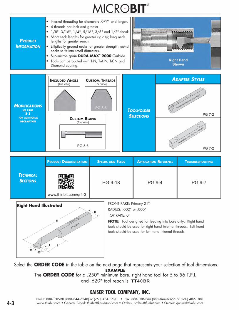
KAISER TOOL COMPANY, INC.Phone: 888-THINBIT (888-844-6248) or (260) 484-3620 • Fax: 888-THINFAX (888-844-6329) or (260) 482-1881www.thinbit.com • General E-mail: [email protected] • Orders: [email protected] • Quotes: [email protected]
Select the ORDER CODE in the table on the next page that represents your selection of tool dimensions.EXAMPLE:
The ORDER CODE for a .250" minimum bore, right hand tool for 5 to 56 T.P.I. and .620" tool reach is: TT40BR
PRODUCTINFORMATION
• Internal threading for diameters .077" and larger.• 4 threads per inch and greater.• 1/8", 3/16", 1/4", 5/16", 3/8" and 1/2" shank.• Short neck lengths for greater rigidity; long neck lengths for greater reach.• Elliptically ground necks for greater strength; round necks to fit into small diameters.• Sub-micron grain DURA-MAX® 2000 Carbide.• Tools can be coated with TiN, TiAIN, TiCN and Diamond coating.
Right HandShown
MODIFICATIONSSEE PAGE
8-3 FOR ADDITIONAL
INFORMATION
INCLUDED ANGLE(TOP VIEW)
CUSTOM THREADS(TOP VIEW)
PG 8-5
CUSTOM BLANK(TOP VIEW)
PG 8-6
TOOLHOLDERSELECTIONS
ADAPTER STYLES
������������� � ���
����
����
��� ���
�����
PG 7-2
TECHNICALSECTIONS
PRODUCT DEMONSTRATION
www.thinbit.com/qr4-3
SPEEDS AND FEEDS
PG 9-18
APPLICATION REFERENCE
PG 9-4
TROUBLESHOOTING
PG 9-7
F
Right Hand Illustrated FRONT RAKE: Primary 21°
RADIUS: .002" or .000"
TOP RAKE: 0°
NOTE: Tool designed for feeding into bore only. Right hand tools should be used for right hand internal threads. Left hand tools should be used for left hand internal threads.
PG 7-2
®

4-4
I.D
. TO
OLS
THREA
DIN
G
I.D. THREADING TOOLS
SPECIFICATIONS ORDER CODE INFORMATION
Minimum Bore
Threads per Inch
Tool Reach DURA-MAX® 2000
CarbideSee Page 9-18 for Speeds and
Feeds information
CoatingsSee Page 9-6 for Expanded Coating
Descriptions
Overall Length Projection Shank
DiameterToolholderPage 7-2
'C' 'E' Use Uncoated Part Number and Add Coating Code 'D' 'F' 'B' Use
Toolholders Beginning
With Minimum Right Hand Left Hand TiN TiCN TiAlN Diamond
.077"Round Neck
40 to 56.291" TT20AR TT20AL
add 'C' add 'D' add 'E' add 'F' 1.397" .014" 1/8" 'AD'.416" TT21AR TT21AL
Over 56.291" TT20AR1 TT20AL1
.416" TT21AR1 TT21AL1
.125"
11 to 56.312" TT20BR TT20BL
add 'C' add 'D' add 'E' add 'F'
1.439" .050"
1/8" 'AD'
.437" TT21BR TT21BL
Over 56.312" TT20BR1 TT20BL1
.437" TT21BR1 TT21BL1
27 to 56.294" TT20CR TT20CL
1.404" .020".419" TT21CR TT21CL
Over 56.294" TT20CR1 TT20CL1
.419" TT21CR1 TT21CL1
.187"
7 to 56.454" TT30BR TT30BL
add 'C' add 'D' add 'E' add 'F'
1.974" .080"
3/16" 'AD'
.704" TT31BR TT31BL
Over 56.454" TT30BR1 TT30BL1
704" TT31BR1 TT31BL1
16 to 56.428" TT30CR TT30CL
1.922" .035".678" TT31CR TT31CL
Over 56.428" TT30CR1 TT30CL1
.678" TT31CR1 TT31CL1
.250"
5 to 56.596" TT40BR TT40BL
add 'C' add 'D' add 'E' add 'F'
2.508" .110"
1/4" 'AD'
.846" TT41BR TT41BL
Over 56.596" TT40BR1 TT40BL1
.846" TT41BR1 TT41BL1
11 to 56.562" TT40CR TT40CL
2.439" .050".812" TT41CR TT41CL
Over 56.562" TT40CR1 TT40CL1
.812" TT41CR1 TT41CL1
.313"
4 to 56.739" TT50BR TT50BL
add 'C' add 'D' add 'E' add 'F'
2.513" .140"
5/16" 'AD'
1.114" TT51BR TT51BL
Over 56.739" TT50BR1 TT50BL1
1.114" TT51BR1 TT51BL1
9 to 56.694" TT50CR TT50CL
2.424" .063"1.069" TT51CR TT51CL
Over 56.694" TT50CR1 TT50CL1
1.069" TT51CR1 TT51CL1
.375"
5 to 56.846" TT60CR TT60CL
add 'C' add 'D' add 'E' add 'F' 2.948" .110" 3/8" 'AD'1.346" TT61CR TT61CL
Over 56.846" TT60CR1 TT60CL1
1.346" TT61CR1 TT61CL1
.500"
4 to 561.119" TT80CR TT80CL
add 'C' add 'D' add 'E' add 'F' 3.434" .150" 1/2" 'AD'1.869" TT81CR TT81CL
Over 561.119" TT80CR1 TT80CL1
1.869" TT81CR1 TT81CL1

KAISER TOOL COMPANY, INC.Phone: 888-THINBIT (888-844-6248) or (260) 484-3620 • Fax: 888-THINFAX (888-844-6329) or (260) 482-1881www.thinbit.com • General E-mail: [email protected] • Orders: [email protected] • Quotes: [email protected]
PRODUCTINFORMATION
• Internal ACME threading for diameters .187" and larger. • 6 threads per inch and greater.• 3/16", 1/4", 5/16" and 3/8".• Short neck lengths for greater rigidity; long neck lengths for greater reach.• Elliptically ground necks for greater strength; round necks to fit into small diameters.• Sub-micron grain DURA-MAX® 2000 Carbide.• Tools can be coated with TiN, TiAIN, TiCN and Diamond coating.
Right HandShown
MODIFICATIONSSEE PAGE
8-3 FOR ADDITIONAL
INFORMATION
INCLUDED ANGLE(TOP VIEW)
CUSTOM THREADS(TOP VIEW)
PG 8-5
CUSTOM BLANK(TOP VIEW)
PG 8-6
TOOLHOLDERSELECTIONS
ADAPTER STYLES
����������
PG 7-2
����
����
��
PG 7-2
TECHNICALSECTIONS
PRODUCT DEMONSTRATION
www.thinbit.com/qr4-5
SPEEDS AND FEEDS
PG 9-18
APPLICATION REFERENCE
PG 9-4
TROUBLESHOOTING
PG 9-7
®

KAISER TOOL COMPANY, INC.Phone: 888-THINBIT (888-844-6248) or (260) 484-3620 • Fax: 888-THINFAX (888-844-6329) or (260) 482-1881www.thinbit.com • General E-mail: [email protected] • Orders: [email protected] • Quotes: [email protected] 4-6
I.D
. A
CM
ETH
REA
DIN
G
I.D. ACME THREADING TOOLS
�
�
�
���
�
������� ��������
Right Hand Illustrated
FRONT RAKE: Primary 21° TOP RAKE: 0° NOTE: Tool designed for feeding into bore only. Right hand tools should be used for right hand internal threads. Left hand tools should be used for left hand internal threads. • 29° ACME threading inserts for internal and external applications. • ACME threading tools can be used to cut other thread profiles by over cutting. • Single lead
ORDERING INSTRUCTIONS
Select the ORDER CODE in the table below that represents your selection of tool dimensions.
EXAMPLE: The ORDER CODE for a .250" minimum bore, right hand tool for 14 or fewer T.P.I.
and .750" tool reach is:AT41B14R
SPECIFICATIONS ORDER CODE INFORMATION
Minimum Bore
Threads per Inch Flat at Tip Tool Reach DURA-MAX® 2000
CarbideSee Page 9-18 for Speeds
and Feeds information
CoatingsSee Page 9-6 for Expanded Coating
Descriptions
Overall Length
Shank Diameter
ToolholderPage 7-2
'C' 'E' Use Uncoated Part Number and Add Coating Code 'D' 'B' Use
Toolholders Beginning
With Minimum Right Hand Left Hand TiN TiCN TiAlN Diamond
.187" 16 .021" .625" AT31B16R AT31B16L
add 'C' add 'D' add 'E' add 'F'
1.902" 3/16"
'AD'
.250" 14 .024" .750" AT41B14R AT41B14L 2.413" 1/4"
.313" 12 .028" 1.000" AT51B12R AT51B12L 2.388" 5/16"
.375" 10 .032" 1.250" AT61C10R AT61C10L 2.893" 3/8"
.375" 6 .057" 1.250" AT61C06R AT61C06L 2.863" 3/8"

KAISER TOOL COMPANY, INC.Phone: 888-THINBIT (888-844-6248) or (260) 484-3620 • Fax: 888-THINFAX (888-844-6329) or (260) 482-1881www.thinbit.com • General E-mail: [email protected] • Orders: [email protected] • Quotes: [email protected]
PRODUCTINFORMATION
• Internal threading for diameters .325" and larger.• 9 threads per inch and greater.• Sub-micron grain DURA-MAX® 2000 and 5000 Carbides.• Inserts available coated with TiN, TiAIN, TiCN and Diamond coating.
Right Hand Toolholder with Left Hand Insert Shown
MODIFICATIONSSEE PAGE
8-3 FOR ADDITIONAL
INFORMATION
INCLUDED ANGLE(TOP VIEW)
CUSTOM THREADS(TOP VIEW)
PG 8-5
TOOLHOLDERSELECTION
ROUND STYLES
������
���
��������
PG 1-6
TECHNICALSECTIONS
PRODUCT DEMONSTRATION
www.thinbit.com/qr4-7
SPEEDS AND FEEDS
PG 9-18
APPLICATION REFERENCE
PG 9-4
TROUBLESHOOTING
PG 9-7
U.S. PATENT NOS. 6,722,825 and 6,974,282

KAISER TOOL COMPANY, INC.Phone: 888-THINBIT (888-844-6248) or (260) 484-3620 • Fax: 888-THINFAX (888-844-6329) or (260) 482-1881www.thinbit.com • General E-mail: [email protected] • Orders: [email protected] • Quotes: [email protected] 4-8
I.D
. TO
OLS
THREA
DIN
G
I.D. THREADING TOOLS
.312"
.063"
.125"
Right Hand Illustrated
FRONT RAKE: 15°
RADIUS: .002" or .000"
TOP RAKE: 0°
ORDERING INSTRUCTIONS
Select the ORDER CODE in the table below that represents your selection of insert specifications.
EXAMPLE: The ORDER CODE for a right hand, 9 to 56 Threads Per Inch
DURA-MAX® 2000 Carbide insert with TiN coating is:MGTTD2RC
SPECIFICATIONS ORDER CODE INFO.
Insert Orientation
Threads per Inch
Insert GradesSee Page 9-5 for Expanded Material Descriptions
and Page 9-18 for Speeds and Feeds
CoatingsSee Page 9-6 for Expanded Coating
Descriptions
Toolholder Page 1-6
DURA-MAX® 2000 Carbide
For Steel & Interrupted Cutting
DURA-MAX® 5000 Carbide
For Aluminum &Nonferrous
Use Uncoated Part Number and Add Coating Code Use Toolholders
Beginning With TiN TiCN TiAlN Diamond
Right Hand
9 to 56 MGTTD2R MGTTD5R
add 'C' add 'D' add 'E' add 'F'
'MGT'
Use left hand holderGreater than 56 MGTTD2R1 MGTTD5R1
Left Hand
9 to 56 MGTTD2L MGTTD5L
add 'C' add 'D' add 'E' add 'F'
'MGT'
Use right hand holderGreater than 56 MGTTD2L1 MGTTD5L1
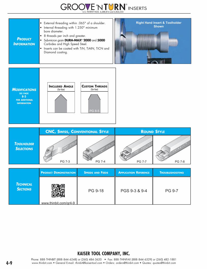
KAISER TOOL COMPANY, INC.Phone: 888-THINBIT (888-844-6248) or (260) 484-3620 • Fax: 888-THINFAX (888-844-6329) or (260) 482-1881www.thinbit.com • General E-mail: [email protected] • Orders: [email protected] • Quotes: [email protected]
U.S. PATENT NOS. 6,688,816 and 6,824,333INSERTS
PRODUCT INFORMATION
• External threading within .065" of a shoulder.• Internal threading with 1.250" minimum bore diameter.• 8 threads per inch and greater.• Sub-micron grain DURA-MAX® 2000 and 5000 Carbides and High Speed Steel.• Inserts can be coated with TiN, TiAIN, TiCN and Diamond coating.
Right Hand Insert & ToolholderShown
MODIFICATIONSSEE PAGE
8-3 FOR ADDITIONAL
INFORMATION
INCLUDED ANGLE(TOP VIEW)
CUSTOM THREADS(TOP VIEW)
PG 8-5
TOOLHOLDERSELECTIONS
CNC, SWISS, CONVENTIONAL STYLE
®
MADE
IN
U.S.A.
THINBIT® KAISER TOOL
3/4" GROOVE
PG 7-3
THINBIT® KAISER TOOL C
3/4" GROOVE ‘N
PG 7-4
ROUND STYLE
����
����
��
�
������
�����
�����
����
�����
����
� ��
PG 7-7
� � � � � �
�
PG 7-8
TECHNICALSECTIONS
PRODUCT DEMONSTRATION
www.thinbit.com/qr4-9
SPEEDS AND FEEDS
PG 9-18
APPLICATION REFERENCE
PGS 9-3 & 9-4
TROUBLESHOOTING
PG 9-7

KAISER TOOL COMPANY, INC.Phone: 888-THINBIT (888-844-6248) or (260) 484-3620 • Fax: 888-THINFAX (888-844-6329) or (260) 482-1881www.thinbit.com • General E-mail: [email protected] • Orders: [email protected] • Quotes: [email protected] 4-10
INSE
RTS
THREA
DIN
G
THREADING INSERTS
.065”
.820"
.145"
.240"
Right Hand Illustrated
FRONT RAKE: 15°
RADIUS: .002" or .000"
TOP RAKE: 0°
ORDERING INSTRUCTIONS
Select the ORDER CODE in the table below that represents your selection of orientation and insert grade.
EXAMPLE: The ORDER CODE for a right hand, 8 to 56 Threads Per Inch threading insert in
DURA-MAX® 2000 is:LGTTD2R
SPECIFICATIONS ORDER CODE INFO.
Insert Orientation
Threads per Inch
Insert GradesSee Page 9-5 for expanded material selections and Page
9-18 for Speeds and Feeds information
CoatingsSee Page 9-6 for Expanded Coating
Descriptions
ToolholderCatalog
Section 7DURA-MAX® 2000 Carbide
For Steel & Interrupted Cutting
DURA-MAX® 5000 CarbideFor Aluminum &
Nonferrous
High Speed Steel Use Uncoated Part Number and
Add Coating Code Use Toolholders Beginning
With TiN TiCN TiAlN Diamond
Right HandFor right hand
external threads or left hand
internal threads
8 to 56 LGTTD2R LGTTD5R LGTTHSR
add 'C' add 'D' add 'E' add 'F'
'L'
Use right hand straight holder
orleft hand 90º
holderGreater than 56 LGTTD2R1 LGTTD5R1 LGTTHSR1
Left HandFor left hand
external threads or right hand
internal threads
8 to 56 LGTTD2L LGTTD5L LGTTHSL
add 'C' add 'D' add 'E' add 'F'
'L'
Use left hand straight holder
orright hand 90º
holderGreater than 56 LGTTD2L1 LGTTD5L1 LGTTHSL1

KAISER TOOL COMPANY, INC.Phone: 888-THINBIT (888-844-6248) or (260) 484-3620 • Fax: 888-THINFAX (888-844-6329) or (260) 482-1881www.thinbit.com • General E-mail: [email protected] • Orders: [email protected] • Quotes: [email protected]
PRODUCT INFORMATION
• External threading within .070" of a shoulder.• Internal ACME threading with 1.250" minimum bore diameter.• 4 threads per inch and greater.• Sub-micron grain DURA-MAX® 2000 and 5000 Carbides and High Speed Steel.• Inserts can be coated with TiN, TiAIN, TiCN and Diamond coating. Right Hand Insert &
Toolholder Shown
MODIFICATIONSSEE PAGE
8-3 FOR ADDITIONAL
INFORMATION
INCLUDED ANGLE(TOP VIEW)
CUSTOM THREADS(TOP VIEW)
PG 8-5
TOOLHOLDERSELECTIONS
CNC, SWISS, CONVENTIONAL STYLE
®
MADE
IN
U.S.A.
THINBIT® KAISER TOOL
3/4" GROOVE
PG 7-3
THINBIT® KAISER TOOL C
3/4" GROOVE ‘N
PG 7-4
ROUND STYLE
����
����
��
�
������
�����
�����
����
�����
����
� ��
PG 7-7
� � � � � �
�
PG 7-8
TECHNICALSECTIONS
PRODUCT DEMONSTRATION
www.thinbit.com/qr4-11
SPEEDS AND FEEDS
PG 9-18
APPLICATION REFERENCE
PGS 9-3 & 9-4
TROUBLESHOOTING
PG 9-7
U.S. PATENT NOS. 6,688,816 and 6,824,333INSERTS
®

KAISER TOOL COMPANY, INC.Phone: 888-THINBIT (888-844-6248) or (260) 484-3620 • Fax: 888-THINFAX (888-844-6329) or (260) 482-1881www.thinbit.com • General E-mail: [email protected] • Orders: [email protected] • Quotes: [email protected] 4-12
ACM
E IN
SERTS
THREA
DIN
G
ACME THREADING INSERTS
.820"
.145"
.240"
Right Hand Illustrated
FRONT RAKE: 15°
TOP RAKE: 0°
• 29° ACME threading inserts for internal and external applications.
• ACME threading tools can be used to cut other thread profiles
by over cutting.
• Single lead
ORDERING INSTRUCTIONS
Select the ORDER CODE in the table below that represents your selection of orientation and insert grade.
EXAMPLE: The ORDER CODE for a right hand ACME threading
insert in DURA-MAX® 2000 with 10 or fewer T.P.I. is:LGAT10D2R
SPECIFICATIONS ORDER CODE INFO.
Insert Orientation
Threads per Inch
Flat at Tip
Insert GradesSee Page 9-5 for expanded material selections and
Page 9-18 for Speeds and Feeds information
CoatingsSee page 9-6 for expanded coating
descriptions
ToolholderCatalogSection 7
DURA-MAX® 2000 Carbide
For Steel & Interrupted Cutting
DURA-MAX® 5000 CarbideFor Aluminum &
Nonferrous
High Speed Steel
Use Uncoated Part Number and Add Coating Code
Use Toolholders Beginning WithTiN TiCN TiAlN Diamond
Centeredright hand, left hand,
internal and external threads
4 .087" LGAT04D2R LGAT04D5R LGAT04HSR
add 'C' add 'D' add 'E' add 'F'
'L'
5 .069" LGAT05D2R LGAT05D5R LGAT05HSRUse right hand straight holder, or left hand 90º holder, for right hand
external threads or left hand internal threads
or
Use left hand straight holder, or right hand
90º holder, for left hand external threads or right
hand internal threads
6 .057" LGAT06D2R LGAT06D5R LGAT06HSR
8 .041" LGAT08D2R LGAT08D5R LGAT08HSR
10 .032" LGAT10D2R LGAT10D5R LGAT10HSR
12 .028" LGAT12D2R LGAT12D5R LGAT12HSR
14 .024" LGAT14D2R LGAT14D5R LGAT14HSR
16 .021" LGAT16D2R LGAT16D5R LGAT16HSR

KAISER TOOL COMPANY, INC.Phone: 888-THINBIT (888-844-6248) or (260) 484-3620 • Fax: 888-THINFAX (888-844-6329) or (260) 482-1881www.thinbit.com • General E-mail: [email protected] • Orders: [email protected] • Quotes: [email protected]
PRODUCT INFORMATION
• Chamfering within .090" of a shoulder.• Internal chamfering with 1.250" minimum bore diameter.• Sub-micron grain DURA-MAX® 2000 and 5000 Carbides and High Speed Steel.• Inserts can be coated with TiN, TiAIN, TiCN and Diamond coating.
Right Hand Toolholder Shown
MODIFICATIONSSEE PAGE
8-3 FOR ADDITIONAL
INFORMATION
INCLUDED ANGLE(TOP VIEW)
CUSTOM THREADS(TOP VIEW)
PG 8-5
TOOLHOLDERSELECTIONS
CNC, SWISS, CONVENTIONAL STYLE
®
MADE
IN
U.S.A.
THINBIT® KAISER TOOL
3/4" GROOVE
PG 7-3
THINBIT® KAISER TOOL C
3/4" GROOVE ‘N
PG 7-4
ROUND STYLE
����
����
��
�
������
�����
�����
����
�����
����
� ��
PG 7-7
� � � � � �
�
PG 7-8
TECHNICALSECTIONS
PRODUCT DEMONSTRATION
www.thinbit.com/qr4-13
SPEEDS AND FEEDS
PG 9-18
APPLICATION REFERENCE
PGS 9-3 & 9-4
TROUBLESHOOTING
PG 9-7
U.S. PATENT NOS. 6,688,816 and 6,824,333INSERTS
®

KAISER TOOL COMPANY, INC.Phone: 888-THINBIT (888-844-6248) or (260) 484-3620 • Fax: 888-THINFAX (888-844-6329) or (260) 482-1881www.thinbit.com • General E-mail: [email protected] • Orders: [email protected] • Quotes: [email protected] 4-14
CH
AM
FERIN
G IN
SERTS
THREA
DIN
G
CHAMFERING INSERTS
.820"
.145"
.240"
FRONT RAKE: 15°
MAXIMUM RADIUS: .002"
TOP RAKE: 0°
ORDERING INSTRUCTIONS
Select the ORDER CODE in the table below that represents your selection of orientation and insert grade.
EXAMPLE: The ORDER CODE for a chamfering insert in DURA-MAX® 2000 is:
LGT45D2
SPECIFICATIONS ORDER CODE INFO.
Insert Orientation
Flat at Tip Insert GradesSee Page 9-5 for expanded material selections and
Page 9-18 for speeds and feeds information
CoatingsSee Page 9-6 for expanded coating descriptions
ToolholderCatalog
Section 7DURA-MAX® 2000 Carbide
For Steel & Interrupted Cutting
DURA-MAX® 5000 CarbideFor Aluminum &
Nonferrous
High Speed Steel
Use Uncoated Part Number and Add Coating Code Use Toolholders
Beginning With TiN TiCN TiAlN Diamond
Centered None LGT45D2 LGT45D5 LGT45HS add 'C' add 'D' add 'E' add 'F' 'L'

KAISER TOOL COMPANY, INC.Phone: 888-THINBIT (888-844-6248) or (260) 484-3620 • Fax: 888-THINFAX (888-844-6329) or (260) 482-1881www.thinbit.com • General E-mail: [email protected] • Orders: [email protected] • Quotes: [email protected]
Scan this code for additional information
www.thinbit.com/qr5-1
PARTI
NG
PRODUCT SELECTION GUIDE - PARTING
PAGE 5-3
• For diameters 1" and smaller• Parting widths .025", .045", .062", .085" & .115"• Typically used for Conventional and Swiss machining, precious metals and small diameter parts
PAGE 1-13
• For diameters 2" and smaller• Parting widths 2, 3, 4, 5 and 6mm• Typically used for CNC machining and large diameter parts
OVER 100,000 TOOLS IN STOCK FORGROOVING • THREADING • PARTING • BORING
TURNING • FACE GROOVINGSPECIALS • FORM TOOLS

KAISER TOOL COMPANY, INC.Phone: 888-THINBIT (888-844-6248) or (260) 484-3620 • Fax: 888-THINFAX (888-844-6329) or (260) 482-1881www.thinbit.com • General E-mail: [email protected] • Orders: [email protected] • Quotes: [email protected] 5-2
PARTI
NG
TOOLING ORIENTATION GUIDE - PARTING
Top ViewTools show cutting edge up.
LeftHand
Counter-Clockwise
Clockwise
LeftHand
LeftHand
RightHand
RightHand
RightHand
Chu
ck

KAISER TOOL COMPANY, INC.Phone: 888-THINBIT (888-844-6248) or (260) 484-3620 • Fax: 888-THINFAX (888-844-6329) or (260) 482-1881www.thinbit.com • General E-mail: [email protected] • Orders: [email protected] • Quotes: [email protected]
PRODUCTINFORMATION
U.S. PATENT NOS. 6,688,816 and 6,824,333PARTING INSERTS
• .025", .045", .062", .085" and .115"• Parting off up to 1" diameter• 0° or 7° lead angle• Centered or Offset• Sub-micron grain DURA-MAX® 2000 and 5000 Carbides and High Speed Steel.• Inserts available with TiN, TiAIN, TiCN and Diamond coating.
MODIFICATIONSSEE PAGE
8-3 FOR ADDITIONAL
INFORMATION
RADII(TOP VIEW)
DEPTH OF CUT(TOP VIEW)
INSERT WIDTH(TOP VIEW)
BACK CLEARANCE(TOP VIEW)
LEAD ANGLE(TOP VIEW)
TOP RAKE(SIDE VIEW)
CHIP BREAKER(SIDE VIEW)
SIDE CLEARANCE(END VIEW)
TOOLHOLDERSELECTIONS
CNC, SWISS, CONVENTIONAL STYLE
®
MADE
IN
U.S.A.
THINBIT® KAISER TOOL
3/4" GROOVE
PG 7-3 PG 7-4
ROUND STYLE
���������
��
�� ���
��� ���������
�����������
PG 7-7
� � � � � � ��
PG 7-8
TECHNICALSECTIONS
PRODUCT DEMONSTRATION
www.thinbit.com/qr5-3
SPEEDS AND FEEDS
PG 9-20
APPLICATION REFERENCE
PGS 9-3 & 9-4
TROUBLESHOOTING
PG 9-7
.145"
.240"
Centered
FRONT RAKE:
CARBIDE: Primary 7° honed, Secondary 15°
HIGH SPEED STEEL: 15°
BACK CLEARANCE:
0° LGPT045HS & LGPT062HS
1° all others
SIDE CLEARANCE: 1°
RADIUS: None
TOP RAKE: 0°
LEAD ANGLE: 0° or 7°
.145"
.240"
Parting Tools with Lead Angle
Centered Right Hand Lead

5-4
INSE
RTS
PARTI
NG
PARTING INSERTS
ORDERING INSTRUCTIONS
Select the ORDER CODE in the table below that represents your selection of groove width and insert grade.EXAMPLE:
The ORDER CODE for an .085" wide parting insert in DURA-MAX® 2000 is:LGPT085D2
SPECIFICATIONS ORDER CODE INFORMATION
Insert Width
InsertOrientation
Lead AngleOrientation
Depth of
Cut
Insert GradesSee Page 9-5 for expanded material descriptions and
Page 9-20 for Speeds and Feeds information
CoatingsSee Page 9-6 for expanded
coating descriptions
Overall Length
ToolholderCatalog
Section 7
'A' 'B' DURA-MAX® 2000
CarbideFor Steel &
Interrupted Cutting
DURA-MAX® 5000 Carbide
For Aluminum &Non-ferrous
High Speed Steel
Use uncoated part number and add coating
code'C' Use
Toolholders Beginning
With ±.001" TiN TiCN TiAlN Diamond
.025"
Centered 0°
.200"
LGPT025D2 LGPT025D5 LGPT025HS
add 'C'
add 'D'
add 'E'
add'F'
.820"Carbide
.825"HSS
'L' Series
Centered Use any
straight holder
or90º holder
Right Hand Use
right hand straight holder
orleft hand
90° holder
Left Hand Use
left hand straight holder
orright hand90° holder
7° Right Hand LGPT025D27R LGPT025D57R LGPT025HS7R
7° Left Hand LGPT025D27L LGPT025D57L LGPT025HS7L
Right Hand 0° LGPT025D2R LGPT025D5R LGPT025HSR
7° Right Hand LGPT025D2R7R LGPT025D5R7R LGPT025HSR7R
7° Left Hand LGPT025D2R7L LGPT025D5R7L LGPT025HSR7L
Left Hand 0° LGPT025D2L LGPT025D5L LGPT025HSL
7° Right Hand LGPT025D2L7R LGPT025D5L7R LGPT025HSL7R
7° Left Hand LGPT025D2L7L LGPT025D5L7L LGPT025HSL7L
.045"
Centered 0°
.500"
LGPT045D2 LGPT045D5 LGPT045HS
1.062"Carbide
1.078"HSS
7° Right Hand LGPT045D27R LGPT045D57R LGPT045HS7R
7° Left Hand LGPT045D27L LGPT045D57L LGPT045HS7L
Right Hand 0° LGPT045D2R LGPT045D5R LGPT045HSR
7° Right Hand LGPT045D2R7R LGPT045D5R7R LGPT045HSR7R
7° Left Hand LGPT045D2R7L LGPT045D5R7L LGPT045HSR7L
Left Hand 0° LGPT045D2L LGPT045D5L LGPT045HSL
7° Right Hand LGPT045D2L7R LGPT045D5L7R LGPT045HSL7R
7° Left Hand LGPT045D2L7L LGPT045D5L7L LGPT045HSL7L
.062"
Centered 0°
.500"
LGPT062D2 LGPT062D5 LGPT062HS
7° Right Hand LGPT062D27R LGPT062D57R LGPT062HS7R
7° Left Hand LGPT062D27L LGPT062D57L LGPT062HS7L
Right Hand 0° LGPT062D2R LGPT062D5R LGPT062HSR
7° Right Hand LGPT062D2R7R LGPT062D5R7R LGPT062HSR7R
7° Left Hand LGPT062D2R7L LGPT062D5R7L LGPT062HSR7L
Left Hand 0° LGPT062D2L LGPT062D5L LGPT062HSL
7° Right Hand LGPT062D2L7R LGPT062D5L7R LGPT062HSL7R
7° Left Hand LGPT062D2L7L LGPT062D5L7L LGPT062HSL7L
.085"
Centered 0°
.500"
LGPT085D2 LGPT085D5 LGPT085HS
7° Right Hand LGPT085D27R LGPT085D57R LGPT085HS7R
7° Left Hand LGPT085D27L LGPT085D57L LGPT085HS7L
Right Hand 0° LGPT085D2R LGPT085D5R LGPT085HSR
7° Right Hand LGPT085D2R7R LGPT085D5R7R LGPT085HSR7R
7° Left Hand LGPT085D2R7L LGPT085D5R7L LGPT085HSR7L
Left Hand 0° LGPT085D2L LGPT085D5L LGPT085HSL
7° Right Hand LGPT085D2L7R LGPT085D5L7R LGPT085HSL7R
7° Left Hand LGPT085D2L7L LGPT085D5L7L LGPT085HSL7L
.115"
Centered 0°
.500"
LGPT115D2 LGPT115D5 LGPT115HS
7° Right Hand LGPT115D27R LGPT115D57R LGPT115HS7R
7° Left Hand LGPT115D27L LGPT115D57L LGPT115HS7L
Right Hand 0° LGPT115D2R LGPT115D5R LGPT115HSR
7° Right Hand LGPT115D2R7R LGPT115D5R7R LGPT115HSR7R
7° Left Hand LGPT115D2R7L LGPT115D5R7L LGPT115HSR7L
Left Hand 0° LGPT115D2L LGPT115D5L LGPT115HSL
7° Right Hand LGPT115D2L7R LGPT115D5L7R LGPT115HSL7R
7° Left Hand LGPT115D2L7L LGPT115D5L7L LGPT115HSL7L
RightHand
LeftHand

6-1
U.S. PATENT NO. 5,638,728
®®
PRODUCTINFORMATION
• 2, 3, 4, 5 and 6mm insert widths.• Recessed pocket and raised edge for chip control.• Internal grooving, external grooving, face grooving and parting.• Sub-micron grain DURA-MAX® 2000 carbide.• Inserts available with TiN, TiAIN, TiCN and Diamond coating.
Page 1-7 Page 2-7
Page 1-13 Page 2-15
INSERTGEOMETRY
SHARP CORNER(TOP VIEW)
CORNER RADIUS(TOP VIEW)
FULL RADIUS(TOP VIEW)
60º THREADING(TOP VIEW)
7° LEAD ANGLE(TOP VIEW)
Right Hand Left Hand
15º(+) TOP RAKE(SIDE VIEW)
15º (-) TOP RAKE(SIDE VIEW)
90º CHAMFERING(TOP VIEW)
TECHNICALSECTIONS
PRODUCT DEMONSTRATION
www.thinbit.com/qr6-1
SPEEDS AND FEEDS
PGS 9-10, 9-12, 9-18 & 9-20
APPLICATION REFERENCE
PGS 9-3 & 9-4
TROUBLESHOOTING
PG 9-7
ORDERING INSTRUCTIONS
Select the ORDER CODE in the table at right that represents your selection of insert geometry and coating.
Please pay special attention to the 'Compatibility' column tomatch the insert with the correct tooling.
The ORDER CODE for a 3mm wide, 'DGI' Styleinsert with .015" radius and TiN coating is
'DGI30BC'
KAISER TOOL COMPANY, INC.Phone: 888-THINBIT (888-844-6248) or (260) 484-3620 • Fax: 888-THINFAX (888-844-6329) or (260) 482-1881www.thinbit.com • General E-mail: [email protected] • Orders: [email protected] • Quotes: [email protected]

6-2
DG
I ST
YLE
OD
/ID
& F
ACE
GRO
OV
ING
INSE
RTS
'DGI' & 'DGMI' STYLE OD/ID AND FACE GROOVING INSERTSSPECIFICATIONS ORDER CODE
InsertWidth+.005"/-.000"
Compatibility InsertGeometry
DURA-MAX® 2000 CarbideSee Page 9-10 or 9-12 for Speeds and Feeds
Uncoated TiN
TiCNNon-stock
TiAlN DiamondNon-stock
.078"(2mm)
Use in all 2mm 'DGP'
Sharp Corner DGI20BU1 DGI20BC1 DGI20BD1 DGI20BE1 DGI20BF1.004" (.10mm) radius DGI20BU2010 DGI20BC2010 DGI20BD2010 DGI20BE2010 DGI20BF2010.008" (.20mm) radius DGI20BU2020 DGI20BC2020 DGI20BD2020 DGI20BE2020 DGI20BF2020.010" (.25mm) radius DGI20BU2025 DGI20BC2025 DGI20BD2025 DGI20BE2025 DGI20BF2025.015" (.38mm) radius DGI20BU DGI20BC DGI20BD DGI20BE DGI20BF.020" (.50mm) radius DGI20BU2050 DGI20BC2050 DGI20BD2050 DGI20BE2050 DGI20BF2050.030" (.75mm) radius DGI20BU2075 DGI20BC2075 DGI20BD2075 DGI20BE2075 DGI20BF2075
Full Radius DGI20BU4 DGI20BC4 DGI20BD4 DGI20BE4 DGI20BF415º (+) Top Rake DGI20BU7P DGI20BC7P DGI20BD7P DGI20BE7P DGI20BF7P15º (-) Top Rake DGI20BU7N DGI20BC7N DGI20BD7N DGI20BE7N DGI20BF7N
7º R.H. Lead Angle DGI20BU3R DGI20BC3R DGI20BD3R DGI20BE3R DGI20BF3R7º L.H. Lead Angle DGI20BU3L DGI20BC3L DGI20BD3L DGI20BE3L DGI20BF3L
.118"(3mm)
Use ONLY with 3mm 'DGPZ' ID tools and
face grooving heads with major diameter codes
'02' and '25'
Sharp Corner DGMI30BU1 DGMI30BC1 DGMI30BD1 DGMI30BE1 DGMI30BF1.015" (.38mm) radius DGMI30BU DGMI30BC DGMI30BD DGMI30BE DGMI30BF
Use in 3mm 'DGP' for OD grooving/parting and major diameters
greater than .984"
Sharp Corner DGI30BU1 DGI30BC1 DGI30BD1 DGI30BE1 DGI30BF1.004" (.10mm) radius DGI30BU2010 DGI30BC2010 DGI30BD2010 DGI30BE2010 DGI30BF2010.008" (.20mm) radius DGI30BU2020 DGI30BC2020 DGI30BD2020 DGI30BE2020 DGI30BF2020.010" (.25mm) radius DGI30BU2025 DGI30BC2025 DGI30BD2025 DGI30BE2025 DGI30BF2025.015" (.38mm) radius DGI30BU DGI30BC DGI30BD DGI30BE DGI30BF.020" (.50mm) radius DGI30BU2050 DGI30BC2050 DGI30BD2050 DGI30BE2050 DGI30BF2050.030" (.75mm) radius DGI30BU2075 DGI30BC2075 DGI30BD2075 DGI30BE2075 DGI30BF2075.040" (1.0mm) radius DGI30BU2100 DGI30BC2100 DGI30BD2100 DGI30BE2100 DGI30BF2100
Full Radius DGI30BU4 DGI30BC4 DGI30BD4 DGI30BE4 DGI30BF415º (+) Top Rake DGI30BU7P DGI30BC7P DGI30BD7P DGI30BE7P DGI30BF7P15º (-) Top Rake DGI30BU7N DGI30BC7N DGI30BD7N DGI30BE7N DGI30BF7N
7º R.H. Lead Angle DGI30BU3R DGI30BC3R DGI30BD3R DGI30BE3R DGI30BF3R7º L.H. Lead Angle DGI30BU3L DGI30BC3L DGI30BD3L DGI30BE3L DGI30BF3L
60º Threading DGI30BU5 DGI30BC5 DGI30BD5 DGI30BE5 DGI30BF590º Chamfering DGI30BU6 DGI30BC6 DGI30BD6 DGI30BE6 DGI30BF6
.157"(4mm)
Use ONLY with 4mm 'DGPZ' ID tools and
face grooving heads with major diameter codes
'02' and '25'
Sharp Corner DGMI40BU1 DGMI40BC1 DGMI40BD1 DGMI40BE1 DGMI40BF1.015" (.38mm) radius DGMI40BU DGMI40BC DGMI40BD DGMI40BE DGMI40BF
Use in 4mm 'DGP' for OD grooving/parting and major diameters
greater than .984"
Sharp Corner DGI40BU1 DGI40BC1 DGI40BD1 DGI40BE1 DGI40BF1.004" (.10mm) radius DGI40BU2010 DGI40BC2010 DGI40BD2010 DGI40BE2010 DGI40BF2010.008" (.20mm) radius DGI40BU2020 DGI40BC2020 DGI40BD2020 DGI40BE2020 DGI40BF2020.010" (.25mm) radius DGI40BU2025 DGI40BC2025 DGI40BD2025 DGI40BE2025 DGI40BF2025.015" (.38mm) radius DGI40BU DGI40BC DGI40BD DGI40BE DGI40BF.020" (.50mm) radius DGI40BU2050 DGI40BC2050 DGI40BD2050 DGI40BE2050 DGI40BF2050.030" (.75mm) radius DGI40BU2075 DGI40BC2075 DGI40BD2075 DGI40BE2075 DGI40BF2075.040" (1.0mm) radius DGI40BU2100 DGI40BC2100 DGI40BD2100 DGI40BE2100 DGI40BF2100
Full Radius DGI40BU4 DGI40BC4 DGI40BD4 DGI40BE4 DGI40BF415º (+) Top Rake DGI40BU7P DGI40BC7P DGI40BD7P DGI40BE7P DGI40BF7P15º (-) Top Rake DGI40BU7N DGI40BC7N DGI40BD7N DGI40BE7N DGI40BF7N
7º R.H. Lead Angle DGI40BU3R DGI40BC3R DGI40BD3R DGI40BE3R DGI40BF3R7º L.H. Lead Angle DGI40BU3L DGI40BC3L DGI40BD3L DGI40BE3L DGI40BF3L
.197"(5mm)
Use in all 5mm 'DGP'
Sharp Corner DGI50BU1 DGI50BC1 DGI50BD1 DGI50BE1 DGI50BF1.004" (.10mm) radius DGI50BU2010 DGI50BC2010 DGI50BD2010 DGI50BE2010 DGI50BF2010.008" (.20mm) radius DGI50BU2020 DGI50BC2020 DGI50BD2020 DGI50BE2020 DGI50BF2020.010" (.25mm) radius DGI50BU2025 DGI50BC2025 DGI50BD2025 DGI50BE2025 DGI50BF2025.015" (.38mm) radius DGI50BU DGI50BC DGI50BD DGI50BE DGI50BF.020" (.50mm) radius DGI50BU2050 DGI50BC2050 DGI50BD2050 DGI50BE2050 DGI50BF2050.030" (.75mm) radius DGI50BU2075 DGI50BC2075 DGI50BD2075 DGI50BE2075 DGI50BF2075.040" (1.0mm) radius DGI50BU2100 DGI50BC2100 DGI50BD2100 DGI50BE2100 DGI50BF2100
Full Radius DGI50BU4 DGI50BC4 DGI50BD4 DGI50BE4 DGI50BF415º (+) Top Rake DGI50BU7P DGI50BC7P DGI50BD7P DGI50BE7P DGI50BF7P15º (-) Top Rake DGI50BU7N DGI50BC7N DGI50BD7N DGI50BE7N DGI50BF7N
7º R.H. Lead Angle DGI50BU3R DGI50BC3R DGI50BD3R DGI50BE3R DGI50BF3R7º L.H. Lead Angle DGI50BU3L DGI50BC3L DGI50BD3L DGI50BE3L DGI50BF3L
.236"(6mm)
Use in all 6mm 'DGP'
Sharp Corner DGI60BU1 DGI60BC1 DGI60BD1 DGI60BE1 DGI60BF1.004" (.10mm) radius DGI60BU2010 DGI60BC2010 DGI60BD2010 DGI60BE2010 DGI60BF2010.008" (.20mm) radius DGI60BU2020 DGI60BC2020 DGI60BD2020 DGI60BE2020 DGI60BF2020.010" (.25mm) radius DGI60BU2025 DGI60BC2025 DGI60BD2025 DGI60BE2025 DGI60BF2025.015" (.38mm) radius DGI60BU DGI60BC DGI60BD DGI60BE DGI60BF.020" (.50mm) radius DGI60BU2050 DGI60BC2050 DGI60BD2050 DGI60BE2050 DGI60BF2050.030" (.75mm) radius DGI60BU2075 DGI60BC2075 DGI60BD2075 DGI60BE2075 DGI60BF2075.040" (1.0mm) radius DGI60BU2100 DGI60BC2100 DGI60BD2100 DGI60BE2100 DGI60BF2100
Full Radius DGI60BU4 DGI60BC4 DGI60BD4 DGI60BE4 DGI60BF415º (+) Top Rake DGI60BU7P DGI60BC7P DGI60BD7P DGI60BE7P DGI60BF7P15º (-) Top Rake DGI60BU7N DGI60BC7N DGI60BD7N DGI60BE7N DGI60BF7N
7º R.H. Lead Angle DGI60BU3R DGI60BC3R DGI60BD3R DGI60BE3R DGI60BF3R7º L.H. Lead Angle DGI60BU3L DGI60BC3L DGI60BD3L DGI60BE3L DGI60BF3L

KAISER TOOL COMPANY, INC.Phone: 888-THINBIT (888-844-6248) or (260) 484-3620 • Fax: 888-THINFAX (888-844-6329) or (260) 482-1881www.thinbit.com • General E-mail: [email protected] • Orders: [email protected] • Quotes: [email protected]
TOO
LHO
LDER
S PRODUCT SELECTION GUIDE - TOOLHOLDERS
www.thinbit.com/qr7-1
Scan this code for
additional information.
ADAPTERS Adapters
• square and round adapters• Use for boring bars and solid carbide tooling
������������� � ���
����
����
��� ���
�����
Page 7-2
®
MADE
IN
U.S.A.
THINBIT® KAISER TOOL COMP ANY, INC.
3/4" GROOVE ‘N
TURN® LGS34R
Page 7-3
SWISS, CNC & CONVENTIONAL STYLEStraight Square
• 5/16", 3/8", 1/2", 5/8", 3/4", 1", 1-1/4" and metric shanks • Right and Left Hand• Use for grooving, face grooving, profiling, threading and parting
90° Square• 5/16", 3/8", 1/2", 5/8", 3/4", 1", 1-1/4" and metric shanks • Right and Left Hand• Use for grooving, face grooving, profiling, threading and parting
THINBIT® KAISER TOOL COMPANY, INC.
3/4" GROOVE ‘N
TURN® LGSF34R
Page 7-4
T H I N B I T®
KAISER TOOL COMPANY, INC.
16MM RH L SERIES
Page 7-5
SWISS STYLESwiss Straight
• 3/8",1/2",10mm, 12mm & 16 mm square shanks• Right and Left Hand• Use for OD grooving
Swiss Face• 3/8", 1/2", 10mm, 12mm & 16mm square shanks• Right Hand• Use for face grooving Page 7-6
�������
��
��
�� ���
��� ��������������������
����������� ���� ����������
Page 7-7
ROUND STYLEReversible
• 1/2", 5/8", 3/4" & 1" shanks• Right and Left Hand• Use for grooving, face grooving, profiling, threading and parting
Internal• 1/2", 5/8", 3/4" & 1" shanks• Right and Left Hand• Use for grooving, face grooving, profiling, threading and parting
� �� �
� ��
�
��� �������������
�������
����������� � ��
Page 7-8
Page 7-9
MULTI-INSERT STYLESquare
• 3/8", 1/2", 5/8", 3/4" & 1" shanks• 1" & 2" pockets• Use for grooving
Round• 1" shank• 1" pocket• Use for grooving
Page 7-10
Page 7-11&12
UNDERCUT STYLE ALTERNATE DGP30º/60º/45º Square
• 3/8", 1/2", 5/8", 3/4" and 1" shanks• Right and Left Hand• Use for making undercuts and profiling
Round & Square• Alternate combinations of Deepgroove® heads and shanks• OD/ID grooving• Face grooving Page 7-13 & 14

KAISER TOOL COMPANY, INC.Phone: 888-THINBIT (888-844-6248) or (260) 484-3620 • Fax: 888-THINFAX (888-844-6329) or (260) 482-1881www.thinbit.com • General E-mail: [email protected] • Orders: [email protected] • Quotes: [email protected] 7-2
ROUND & SQUARE ADAPTERS
PRODUCTINFORMATION
• Designed to adapt round tooling to lathe workholding• ID sizes 1/8", 5/32", 3/16", 1/4", 5/16" and 3/8".• Round sizes 1/4", 3/8", 1/2", 5/8" and 3/4".• Square sizes 5/16", 3/8", 1/2", 5/8", 3/4", 1" and 1-1/4".• Modifications can be provided on any of our tooling. Please contact us with your application requirements.
��������� ����������
�
��
�
����
����
��� ���
�����
�
�
�
�
TOOLSELECTIONS
SOLID CARBIDE GROOVING BARS
�����
BORING BARS
MBAPage 3-13
MBBPage 3-15
MBCPage 3-17
MBEPage 3-8
MBFPage 3-9
MBGPage 3-10
www.thinbit.com/qr7-2
Scan this code for additional information.
ORDERING INSTRUCTIONS
Select the ORDER CODE in the table below that represents your selection of adapter dimensions.EXAMPLE:
The ORDER CODE for a .375" ID x .625" OD round adapter is:AD3762
SPECIFICATIONS ORDER CODE SPECIFICATIONS ORDER CODEAdapter
StyleShank Dimensions Adapter Replacement Parts Adapter
StyleShank Dimensions Adapter Replacement Parts
'A' 'B' 'C' Includes Adapter and
Hardware
'A' 'B' 'C' Includes Adapter and
HardwareScrew Wrench Pin Screw Wrench Pin
Round
.125"
.250"
3.000"
AD1225 S1402M W0050 P0203
Round
.312"
.500"
4.000"
AD3150 S1802 W1005 P0204.375" AD1237 S1402 W0050 P0203 .625" AD3162 S1802 W1005 P0206.500" AD1250 S1402 W0050 P0204 .750" AD3175 S1802 W1005 P0206.625" AD1262 S1404 W0050 P0204 1.000" AD3110 S1804 W1005 P0206
.750" AD1275 S1404 W0050 P0204.375"
.625"4.000"
AD3762 S1802 W1005 P02061.000" AD1210 S1404 W0050 P0204 .750" AD3775 S1802 W1005 P0206
.156".375"
3.000"AD1537 S1402M W0050 --- 1.000" AD3710 S1804 W1005 P0206
.500" AD1550 S1402 W0050 ---.500"
.750"4.000"
AD5075 S1802 W1005 P0206.625" AD1562 S1403 W0050 --- 1.000" AD5010 S1804 W1005 P0206
.187"
.375"
3.000"
AD1837 S1402M W0050 P0203 .750" 1.000" 4.000" AD7510 S1802 W1005 ---.500" AD1850 S1802 W1005 P0204.625" AD1862 S1802 W1005 P0206.750" AD1875 S1804 W1005 P0206
Square
.250".312"
3.000"AD56 --- --- ---
1.000" AD1810 S1404 W0050 P0206 .375" AD38 S1802 W1005 ---
.250"
.375"
4.000"
AD2537 S1402M W0050 P0203
.250"&
.375"
.500"
3.000"
AD12 S1802 W1005 ---.500" AD2550 S1802 W1005 P0204 .625" AD58 S1802 W1005 ---.625" AD2562 S1802 W1005 P0206 .750" AD34 S1802 W1005 ---.750" AD2575 S1804 W1005 P0206 1.000" AD01 S1802 W1005 ---
1.000" AD2510 S1804 W1005 P0206 1.250" AD14 S1802 W1005 ---
TOO
LHO
LDER
S
GroovingPage 1-3
Face GroovingPage 2-3BoringPage 3-3
ThreadingPage 4-3 & 4-5
GroovingPage 1-5
Face GroovingPage 2-5

KAISER TOOL COMPANY, INC.Phone: 888-THINBIT (888-844-6248) or (260) 484-3620 • Fax: 888-THINFAX (888-844-6329) or (260) 482-1881www.thinbit.com • General E-mail: [email protected] • Orders: [email protected] • Quotes: [email protected]
U.S. PATENT NOS. 6,688,816 and 6,824,333STRAIGHT TOOLHOLDERS
PRODUCTINFORMATION
• Designed for CNC, conventional and top slide position on Swiss screw machines.• Shank sizes 5/16", 3/8", 1/2" , 5/8", 3/4", 1" and 1-1/4". Metric sizes also available.• Modifications can be provided on any of our tooling. Please contact us with your application requirements.
B
A
C
®
MADE
IN
U.S.A.
THINBIT® KAISER TOOL COMPANY, INC.
3/4" GROOVE ‘N
TURN® LGS34R
Right Hand Illustrated
INSERTSELECTIONS
GROOVING
�������
�
��
��� �
PG 1-9
FACE GROOVING
PG 2-9
THREADING
�������
�
���
� �
PG 4-9
PARTING
PG 5-3
www.thinbit.com/qr7-3
Scan this code for additional information.
ORDERING INSTRUCTIONS
Select the ORDER CODE in the table below that represents your selection of shank dimensions.EXAMPLE:
The ORDER CODE for a .750" Right Hand square shank for inserts beginning with 'L' is:LGS34R
SPECIFICATIONS ORDER CODEShank
Orientation Shank Dimensions Toolholder PackageIncludes Shank, Clamp and Hardware Replacement Parts
'A' 'B' 'C'For Inserts Beginning
With 'L'RIGHTHAND
LEFTHAND Clamp Screw Wrench Pin
Straight
Use right hand holder
with right hand inserts
Use left hand holder
with left hand inserts
.312" .500" 4.840" LGS56R LGS56L
Right Hand:Clamp X
Left Hand:Clamp Y
S3808 W1005 P0206
.375" .500" 4.840" LGS38R LGS38L
.500" .500" 4.840" LGS12R LGS12L
.625" .625" 4.840" LGS58R LGS58L
.750" .750" 4.840" LGS34R LGS34L1.000" 1.000" 4.840" LGS01R LGS01L1.250" 1.250" 4.840" LGS14R LGS14L8mm .500" 4.840" LGS08RM LGS08LM10mm .500" 4.840" LGS10RM LGS10LM12mm .500" 4.840" LGS12RM LGS12LM16mm .750" 4.840" LGS16RM LGS16LM20mm 1.000" 4.840" LGS20RM LGS20LM25mm 1.000" 4.840" LGS25RM LGS25LM
®

KAISER TOOL COMPANY, INC.Phone: 888-THINBIT (888-844-6248) or (260) 484-3620 • Fax: 888-THINFAX (888-844-6329) or (260) 482-1881www.thinbit.com • General E-mail: [email protected] • Orders: [email protected] • Quotes: [email protected] 7-4
PRODUCTINFORMATION
• Designed for CNC and conventional machines.• Shank sizes 5/16", 3/8", 1/2" , 5/8", 3/4", 1" and 1-1/4". Metric sizes also available.• Modifications can be provided on any of our tooling. Please contact us with your application requirements.
C
B
A
®
THINBIT® KAISER TOOL COMPANY, INC.
3/4" GROOVE ‘N
TURN® LGSF34R
MADE
IN
U.S.A.
Right Hand Illustrated
INSERTSELECTIONS
GROOVING
�������
�
��
��� �
PG 1-9
FACE GROOVING
PG 2-9
THREADING
�������
�
���
� �
PG 4-9
PARTING
PG 5-3
www.thinbit.com/qr7-4
Scan this code for additional information.
ORDERING INSTRUCTIONS
Select the ORDER CODE in the table below that represents your selection of shank orientation and dimensions.EXAMPLE:
The ORDER CODE for a .750" right hand shank for inserts beginning with 'L' is:LGSF34R
SPECIFICATIONS ORDER CODE
ShankOrientation Shank Dimensions
Toolholder PackageIncludes Shank, Clamp and Hardware
For Inserts BeginningWith 'L'
Replacement Parts
'A' 'B' 'C' Clamp Screw Wrench PinRIGHTHAND
LEFTHAND
90º
Use right hand holder
with left hand inserts
Use left hand holder
with right hand
inserts
.312" .500" 4.840" LGSF56R
Clamp C S3808 W1005 P0312
.375" .500" 4.840" LGSF38R
.500" .500" 4.840" LGSF12R
.625" .625" 4.840" LGSF58R LGSF58L
.750" .750" 4.840" LGSF34R LGSF34L
1.000" 1.000" 4.840" LGSF01R LGSF01L
1.250" 1.250" 4.840" LGSF14R LGSF14L
8mm .500" 4.840" LGSF08RM
10mm .500" 4.840" LGSF10RM
12mm .500" 4.840" LGSF12RM
16mm .750" 4.840" LGSF16RM LGSF16LM
20mm 1.000" 4.840" LGSF20RM LGSF20LM
25mm 1.000" 4.840" LGSF25RM LGSF25LM
90º TOOLHOLDERS®
U.S. PATENT NOS. 6,688,816 and 6,824,333
GRO
OV
E 'N
TU
RN
®
TOO
LHO
LDER
S

KAISER TOOL COMPANY, INC.Phone: 888-THINBIT (888-844-6248) or (260) 484-3620 • Fax: 888-THINFAX (888-844-6329) or (260) 482-1881www.thinbit.com • General E-mail: [email protected] • Orders: [email protected] • Quotes: [email protected]
PRODUCTINFORMATION
• Designed for top slide position on Swiss screw machines.• Shank sizes 1/2", 12mm and 16mm in right hand orientation.• Modifications can be provided on any of our tooling. Please contact us with your application requirements.
T H I N B I T®
KAISER TOOL COMPANY, INC.
16MM RH L SERIESC
B
A
Right Hand Illustrated
INSERTSELECTIONS
GROOVING
�������
�
��
��� �
PG 1-9
THREADING
�������
�
���
� �
PG 4-9 PG 5-3
www.thinbit.com/qr7-5
Scan this code for additional information.
ORDERING INSTRUCTIONS
Select the ORDER CODE in the table below that represents your selection of shank orientation and dimensions.EXAMPLE:
The ORDER CODE for a .500" shank, right hand tool for inserts beginning with 'L' is:LSS12R
SPECIFICATIONS ORDER CODE
ShankOrientation
Shank Dimensions Toolholder PackageIncludes Shank, Clamp and Hardware Replacement Parts
'A' 'B' 'C' For Inserts Beginning WithClamp Screw Wrench Pin
'L'
Right Hand
Use with right hand and
centered inserts
.500" .500"
4.840"
LSS12R
Clamp C S3808 W1005 P0305
12mm 12mm LSS12RM
16mm 16mm LSS16RM
Left Hand
Use with left hand and
centered inserts
.500" .500"
4.840"
LSS12L
12mm 12mm LSS12LM
16mm 16mm LSS16LM
PARTING
U.S. PATENT NOS. 6,688,816 and 6,824,333SWISS SCREW MACHINE TOOLHOLDERS
®

KAISER TOOL COMPANY, INC.Phone: 888-THINBIT (888-844-6248) or (260) 484-3620 • Fax: 888-THINFAX (888-844-6329) or (260) 482-1881www.thinbit.com • General E-mail: [email protected] • Orders: [email protected] • Quotes: [email protected] 7-6
SWISS SCREW MACHINE FACE GROOVING TOOLHOLDERS
PRODUCTINFORMATION
• Designed for top slide position on Swiss screw machines.• Shank sizes 3/8", 1/2", 10mm, 12mm and 16mm in right hand orientation.• Modifications can be provided on any of our tooling. Please contact us with your application requirements.
�
�
�
��
��
�� ���
������
����� �
�������������������
��"�� �#��� ������� �� ��� # �"�
Right Hand Illustrated
INSERTSELECTIONS
FACE GROOVING
PG 2-9 www.thinbit.com/qr7-6
Scan this code for additional information.
ORDERING INSTRUCTIONS
Select the ORDER CODE in the table below that represents your selection of shank orientation and dimensions.EXAMPLE:
The ORDER CODE for a .375" Right Hand shank for inserts beginning with 'L' is:LSSFG38R
SPECIFICATIONS ORDER CODE
ShankOrientation Shank Dimensions
Toolholder PackageIncludes Shank, Clamp and
HardwareReplacement Parts
'A' 'B' 'C' For Inserts Beginning With
'L' Clamp Screw Wrench Pin
Right Hand
Use with left hand and centered inserts for counter-clockwise
rotation
.375" .375" 4.840" LSSFG38R
Clamp C S3808 W1005 P0203
.500" .500" 4.840" LSSFG12R
10mm 10mm 4.840" LSSFG10RM
12mm 12mm 4.840" LSSFG12RM
16mm 16mm 4.840" LSSFG16RM
U.S. PATENT NOS. 6,688,816 and 6,824,333
SWIS
STO
OLH
OLD
ERS
®

KAISER TOOL COMPANY, INC.Phone: 888-THINBIT (888-844-6248) or (260) 484-3620 • Fax: 888-THINFAX (888-844-6329) or (260) 482-1881www.thinbit.com • General E-mail: [email protected] • Orders: [email protected] • Quotes: [email protected]
U.S. PATENT NOS. 6,688,816 and 6,824,333ROUND REVERSIBLE TOOLHOLDERS
PRODUCTINFORMATION
• Designed for boring bar positions on all machines.• Can be used with a boring head to trepan on a mill. Shank may need to be shortened.• Toolholder reversible by removing face and bottom screws and rotating head 1/2 turn.• Shank sizes 1/2", 5/8", 3/4" and 1".• All 1/2", 5/8" and 3/4" shanks are made from 1" shank.• Modifications can be provided on any of our tooling. Please contact us with your application requirements.
�������
�
���
������� ��������� ��
��
$������� ������$�
��
��
�� ���
Right Hand Illustrated
INSERTSELECTIONS
GROOVING
�������
�
��
��� �
PG 1-9
FACE GROOVING
PG 2-9
THREADING
�������
�
���
� �
PG 4-9
PARTING
PG 5-3
www.thinbit.com/qr7-7
Scan this code for additional information.
ORDERING INSTRUCTIONS
Select the ORDER CODE in the table below that represents your selection of shank dimensions.EXAMPLE:
The ORDER CODE for a .625" round shank for inserts beginning with 'L' is:LROE58
SPECIFICATIONS ORDER CODEShank
OrientationShank
DimensionsToolholder Package
Includes Shank, Head, Clamp and Hardware
Replacement Parts
'A' For Inserts Beginning WithHead Only
Includes Clamp and HardwareFor Inserts Beginning With Head
ScrewsHead
Wrenches Shank Clamp ClampHardware
'L' 'L'
Right Hand orLeft Hand
Use as right hand with right hand inserts; Use as
left hand with left hand inserts; Use as either hand
with centered inserts.
.500" LROE12
LROEH1 each:S5806S2810
1 each:W1006W1009
RROE12
Clamp C
Screw:S3808
Wrench:W1005
.625" LROE58 RROE58
.750" LROE34 RROE34
1.000" LROE01 RROE01
1"
5.5"
A
®

KAISER TOOL COMPANY, INC.Phone: 888-THINBIT (888-844-6248) or (260) 484-3620 • Fax: 888-THINFAX (888-844-6329) or (260) 482-1881www.thinbit.com • General E-mail: [email protected] • Orders: [email protected] • Quotes: [email protected] 7-8
U.S. PATENT NOS. 6,688,816 and 6,824,333ROUND INTERNAL TOOLHOLDERS
PRODUCTINFORMATION
• Designed for boring bar positions on all machines.
• Toolholder reversible for left and right hand orientation.
• Shank sizes 1/2", 5/8", 3/4" and 1".
• All 1/2", 5/8" and 3/4" shanks are made from 1" shank.
• Modifications can be provided on any of our tooling. Please contact us with your application requirements.
Right Hand Illustrated
INSERTSELECTIONS
GROOVING
�������
�
��
��� �
PG 1-9
FACE GROOVING
PG 2-9
THREADING
�������
�
���
� �
PG 4-9
PARTING
PG 5-3
www.thinbit.com/qr7-8
Scan this code for additional information.
ORDERING INSTRUCTIONS
Select the ORDER CODE in the table below that represents your selection of shank orientation and dimensions.EXAMPLE:
The ORDER CODE for a .625" right hand shank for inserts beginning with 'L' is:LR5806
SPECIFICATIONS ORDER CODEShank
OrientationMinimum
BoreDiameter
Shank Dimensions Toolholder PackageIncludes Shank, Clamp and
Hardware
Replacement Parts
'A' 'C' For Inserts Beginning With
without pin 'L' Clamp Screw Wrench Pin
Right Hand orLeft Hand
Use as right hand with left hand inserts; Use as
left hand with right hand inserts; Use
as either hand with
centered inserts.
1.250"
.500"
5.500"
LR1206
Clamp C S3808 W1005 P0305
.625" LR5806
.750" LR3406
1.000"5.500" LR0106
11.875" LR0112
1"
C
A
RO
UN
DTO
OLH
OLD
ERS
®

KAISER TOOL COMPANY, INC.Phone: 888-THINBIT (888-844-6248) or (260) 484-3620 • Fax: 888-THINFAX (888-844-6329) or (260) 482-1881www.thinbit.com • General E-mail: [email protected] • Orders: [email protected] • Quotes: [email protected]
MULTI-INSERT SQUARE TOOLHOLDERS
PRODUCTINFORMATION
• Designed to reduce cycle time on those machines with adequate horsepower to handle the tool pressure.• Pocket is filled with any selection of insert geometry and lengths. Proper edge to edge relation maintained with spacer blocks.• Shank sizes 3/8", 1/2", 5/8", 3/4" and 1".• Pocket sizes 1" and 2".• Modifications can be provided on any of our tooling. Please contact us with your application requirements.
INSERT SELECTION
Due to the potential complexity of configuring these toolholders, we recommend calling for assistance.
See Page 8-7
www.thinbit.com/qr7-9
Scan this code for additional information.
ORDERING INSTRUCTIONS
Select the ORDER CODE in the table below that represents your selection of shank dimensions.EXAMPLE:
The ORDER CODE for a 1" pocket on a 1" square shank is:EM010101
SPECIFICATIONS ORDER CODEPocket
SizeShank Dimensions Toolholder
PackageIncludes Shank,Pocket, Clampand Hardware
Replacement Parts
'A' 'B' 'C'Pocket
Includes Hardware
Call For Inserts
Call For Inserts
PocketHardware Backplate Shank Clamp Clamp
Hardware
1"Pocket
.375"
1.000" 4.840"
EM013801
HM0101 Screw:2 eachS1604S3810
Wrench:1 each:W1004W1005
---
ESM0138
Clamp MScrew:2 eachS3808
Wrench:W1005
.500" EM011201 ESM0112
.625" EM015801 ESM0158
.750" EM013401 ESM0134
1.000" EM010101 ESM0101
2"Pocket
.375"
1.000" 4.840"
EM013802
HM0102
Backplate:BP0002
Screws:4 eachS5404
ESM0138
Clamp N
.500" EM011202 ESM0112
.625" EM015802 ESM0158
.750" EM013402 ESM0134
1.000" EM010102 ESM0101
C
B
A

KAISER TOOL COMPANY, INC.Phone: 888-THINBIT (888-844-6248) or (260) 484-3620 • Fax: 888-THINFAX (888-844-6329) or (260) 482-1881www.thinbit.com • General E-mail: [email protected] • Orders: [email protected] • Quotes: [email protected] 7-10
MULTI-INSERT ROUND TOOLHOLDERS
PRODUCTINFORMATION
• Designed to reduce cycle time on those machines with adequate horsepower to handle the tool pressure.• Pocket is filled with any selection of insert geometry and lengths. Proper edge to edge relation maintained with spacer blocks.• Shank size 1".• Pocket size 1".• Modifications can be provided on any of our tooling. Please contact us with your application requirements.
Right Hand Illustrated
INSERT SELECTION
Due to the potential complexity of configuring these toolholders, we recommend calling for assistance.
See Page 8-7
www.thinbit.com/qr7-10
Scan this code for additional information.
ORDERING INSTRUCTIONS
Select the ORDER CODE in the table below that represents your selection of shank dimensions.EXAMPLE:
The ORDER CODE for a 1" right hand shank, 5.5" long is:ROM0106
SPECIFICATIONS ORDER CODE
Pocket Size&
ShankOrientation
MinimumBore
Diameter
Shank DimensionsToolholder Package
Includes Shank and Hardware
Replacement Parts
'A' 'C'Call For Inserts
EndScrews
ClampingScrews Wrench Pin
1" PocketRight Hand
1.125"Varies dependingon confi guration
1.000"5.500" ROM0106
2 each:S1804
9 each:S1808 W1005 P0001
11.875" ROM0112 MU
LTI-
INSE
RT
TOO
LHO
LDER
S

KAISER TOOL COMPANY, INC.Phone: 888-THINBIT (888-844-6248) or (260) 484-3620 • Fax: 888-THINFAX (888-844-6329) or (260) 482-1881www.thinbit.com • General E-mail: [email protected] • Orders: [email protected] • Quotes: [email protected]
PRODUCTINFORMATION
• Designed for making angled undercuts.• Toolholder must be used with inserts that have radial relief.• Groove widths less than .080" may require a special insert.• Shank sizes 3/8", 1/2", 5/8", 3/4" and 1".• Modifications can be provided on any of our tooling. Please contact us with your application requirements. 45° Right Hand Illustrated
INSERTSELECTIONS
FACE GROOVING
PG 2-9
Due to the potential complexity ofconfiguring these toolholders,
we recommend calling for assistance.
www.thinbit.com/qr7-11
Scan this code for additional information
45° ILLUSTRATED
Counter-clockwise
Clockwise
RH
LH
APPLICATION EXAMPLESTOP VIEW, CUTTING EDGE UP
RIGHT HAND HOLDERPERPENDICULAR TOPART CENTERLINE
DE
RIGHT HAND HOLDERPARALLEL TO
PART CENTERLINERH
RH
LH
LH
U.S. PATENT NOS. 6,688,816 and 6,824,33345° & 30°/60° TOOLHOLDERS
®
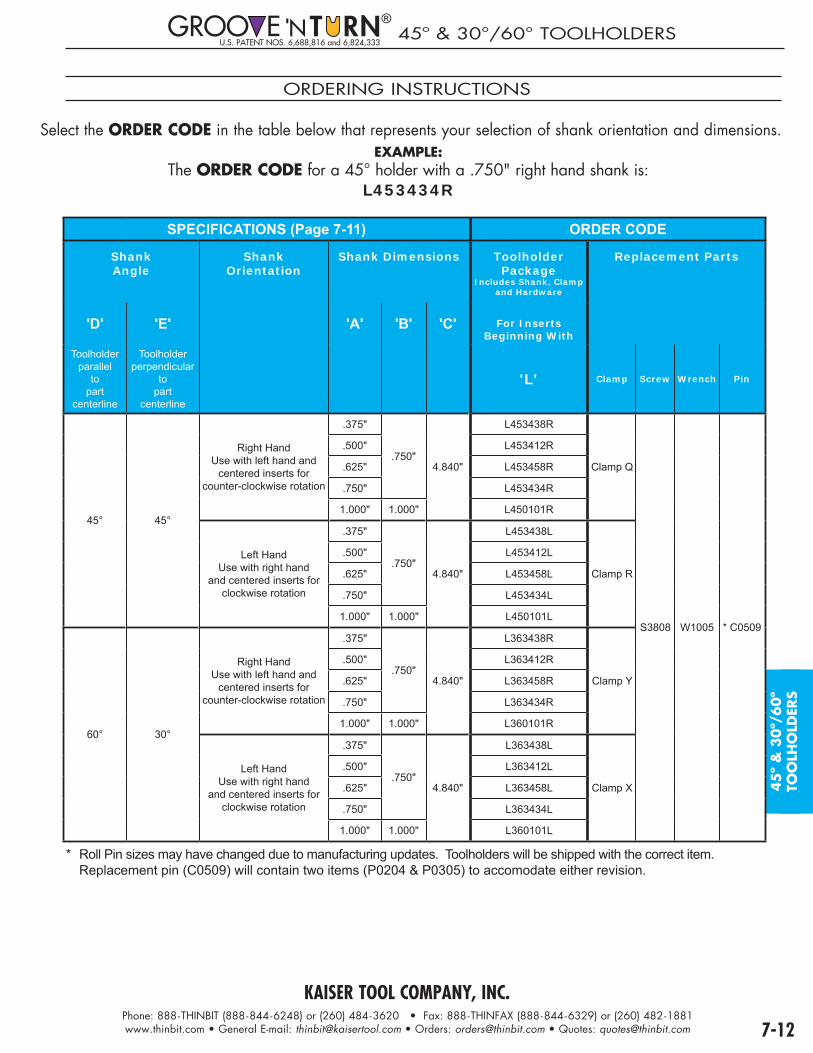
KAISER TOOL COMPANY, INC.Phone: 888-THINBIT (888-844-6248) or (260) 484-3620 • Fax: 888-THINFAX (888-844-6329) or (260) 482-1881www.thinbit.com • General E-mail: [email protected] • Orders: [email protected] • Quotes: [email protected] 7-12
45
º &
30
º/60º
TOO
LHO
LDER
S
U.S. PATENT NOS. 6,688,816 and 6,824,33345º & 30°/60° TOOLHOLDERS
ORDERING INSTRUCTIONS
Select the ORDER CODE in the table below that represents your selection of shank orientation and dimensions.EXAMPLE:
The ORDER CODE for a 45° holder with a .750" right hand shank is:L453434R
SPECIFICATIONS (Page 7-11) ORDER CODE
ShankAngle
ShankOrientation
Shank Dimensions Toolholder Package
Includes Shank, Clamp and Hardware
Replacement Parts
'D' 'E' 'A' 'B' 'C' For Inserts Beginning With
Toolholderparallel
topart
centerline
Toolholderperpendicular
topart
centerline
'L' Clamp Screw Wrench Pin
45° 45°
Right HandUse with left hand and
centered inserts for counter-clockwise rotation
.375"
.750"4.840"
L453438R
Clamp Q
S3808 W1005 * C0509
.500" L453412R
.625" L453458R
.750" L453434R
1.000" 1.000" L450101R
Left HandUse with right hand
and centered inserts for clockwise rotation
.375"
.750"4.840"
L453438L
Clamp R
.500" L453412L
.625" L453458L
.750" L453434L
1.000" 1.000" L450101L
60° 30°
Right HandUse with left hand and
centered inserts for counter-clockwise rotation
.375"
.750"4.840"
L363438R
Clamp Y
.500" L363412R
.625" L363458R
.750" L363434R
1.000" 1.000" L360101R
Left HandUse with right hand
and centered inserts for clockwise rotation
.375"
.750"4.840"
L363438L
Clamp X
.500" L363412L
.625" L363458L
.750" L363434L
1.000" 1.000" L360101L
* Roll Pin sizes may have changed due to manufacturing updates. Toolholders will be shipped with the correct item. Replacement pin (C0509) will contain two items (P0204 & P0305) to accomodate either revision.
®

7-13
U.S. PATENT NO. 5,638,728
®®
ROUND SHANKS WITH EXTERNAL HEADS
RIGHT HAND, CLOCKWISE
O
P
LEFT HAND, COUNTER-CLOCKWISE
RIGHT HAND, OD
Q
R
LEFT HAND, OD
SPECIFICATIONS ORDER CODEInsert Width
Depth of Cut
Package Style
Inserts ToolholderPackage
Includes Shank, Head, Clamp and Hardware
Inserts Replacement Parts
Page 6-1
Use Inserts Beginning
With
Use Inserts Beginning
With
Head HeadHardware
Shank34 = 3/4"01 = 1"
20 = 20mm25 = 25mm
Clamp ClampHardware
See Above
3/4" Shank3/4"Ø x 7"
1" Shank1"Ø x 7"
2mm (.078")
13mm (1/2")
O
'DGI2'
DGPO201334_ _ DGPO201301_ _ 'DGI2'
(Page 6-1)
DGH32013_ _
Screw:2 eachS7552
Wrench:W4025
DGS_ _ZR DGC12013
Screw:S6552
Wrench:W4025
Q* DGPQ201334 DGPQ201301 DGH12013
P DGPP201334_ _ DGPP201301_ _ DGH42013_ _DGS_ _ZL DGC22013
R* DGPR201334 DGPR201301 DGH22013
3mm (.118")
13mm (1/2")
OUse 'DGMI3' for major diameter
codes'02'&'25'
'DGI3' for all others
DGPO301334_ _ DGPO301301_ _ Use 'DGMI3' for major diameter
codes'02'&'25'
'DGI3' for all others
(Page 6-1)
DGH33013_ _DGS_ _ZR DGC13013
Q* DGPQ301334 DGPQ301301 DGH13013
P DGPP301334_ _ DGPP301301_ _ DGH43013_ _DGS_ _ZL DGC23013
R* DGPR301334 DGPR301301 DGH23013
4mm (.157")
13mm (1/2")
O
Use 'DGMI4'for major
diameter codes'02'&'25'
'DGI4' for all others
DGPO401334_ _ DGPO401301_ _
Use 'DGMI4'for major
diameter codes'02'&'25'
'DGI4' for all others
(Page 6-1)
DGH34013_ _DGS_ _ZR DGC14013
Q* DGPQ401334 DGPQ401301 DGH14013
P DGPP401334_ _ DGPP401301_ _ DGH44013_ _DGS_ _ZL DGC24013
R* DGPR401334 DGPR401301 DGH24013
20mm (3/4")
O DGPO402034_ _ DGPO402001_ _ DGH34020_ _DGS_ _ZR DGC14020
Q* DGPQ402034 DGPQ402001 DGH14020
P DGPP402034_ _ DGPP402001_ _ DGH44020_ _DGS_ _ZL DGC24020
R* DGPR402034 DGPR402001 DGH24020
5mm (.197")
13mm (1/2")
O
'DGI5'
DGPO501334_ _ DGPO501301_ _
'DGI5'
(Page 6-1)
DGH35013_ _DGS_ _ZR DGC15013
Q* DGPQ501334 DGPQ501301 DGH15013
P DGPP501334_ _ DGPP501301_ _ DGH45013_ _DGS_ _ZL DGC25013
R* DGPR501334 DGPR501301 DGH25013
25mm (1")
O DGPO502534_ _ DGPO502501_ _ DGH35025_ _DGS_ _ZR DGC15025
Q* DGPQ502534 DGPQ502501 DGH15025
P DGPP502534_ _ DGPP502501_ _ DGH45025_ _DGS_ _ZL DGC25025
R* DGPR502534 DGPR502501 DGH25025
6mm (.236")
13mm (1/2")
O
'DGI6'
DGPO601334_ _ DGPO601301_ _
'DGI6'
(Page 6-1)
DGH36013_ _DGS_ _ZR DGC16013
Q* DGPQ601334 DGPQ601301 DGH16013
P DGPP601334_ _ DGPP601301_ _ DGH46013_ _DGS_ _ZL DGC26013
R* DGPR601334 DGPR601301 DGH26013
25mm (1")
O DGPO602534_ _ DGPO602501_ _ DGH36025_ _DGS_ _ZR DGC16025
Q* DGPQ602534 DGPQ602501 DGH16025
P DGPP602534_ _ DGPP602501_ _ DGH46025_ _DGS_ _ZL DGC26025
R* DGPR602534 DGPR602501 DGH26025
Major DiameterRange
InsertWidth Code Insert
StyleMajor Diameter
RangeInsertWidth Code Insert
Style
.787"- .885" (20-22.5mm) 2mm 02 DGI1.377"-1.574" (35-40mm)
2mm 50 DGI3 & 4mm 02 DGMI 3, 4, 5 & 6mm 34 DGI
.885"- .984" (22.5-25mm) 2mm 25 DGI 1.574"-1.968" (40-50mm)
All
45 DGI3 & 4mm 25 DGMI 1.968"-2.362" (50-60mm) 56 DGI
.984"-1.082" (25-27.5mm) 2mm 57 DGI 2.362"-2.952" (60-75mm) 67 DGI3, 4, 5 & 6mm 23 DGI 2.952"-3.937" (75-100mm) 71 DGI
1.082"-1.181" (27.5-30mm) 2mm 70 DGI 3.937"-5.905" (100-150mm) 11 DGI3, 4, 5 & 6mm 23 DGI 5.905"-11.811" (150-300mm) 13 DGI
1.181"-1.377" (30-35mm) 2mm 05 DGI 11.811"- ∞ (300mm-∞) 30 DGI3, 4, 5 & 6mm 34 DGI
Note:As long as first plunge is made within major diameter range and each following plunge overlaps, groove width can be increased toward or away from center of part.
PACKAGE STYLE
PACKAGE STYLE
* Codes not required on Q and R packages

7-14
DEE
PG
RO
OV
E®A
LTER
NA
TE P
KG
S
U.S. PATENT NO. 5,638,728
®®
SQUARE SHANKS WITH INTERNAL FACE GROOVING HEADS
PACKAGE STYLE
S
T
LEFT HAND, CLOCKWISE
RIGHT HANDCOUNTER-CLOCKWISE
PACKAGE STYLE
U
RIGHT HAND, CLOCKWISE
PACKAGE STYLE
V
LEFT HAND, COUNTER-CLOCKWISE
SPECIFICATIONS ORDER CODE
Insert Width
Depth of Cut
Package Style
ToolholderPackage
Includes Shank, Head, Clamp and Hardware
Inserts Replacement Parts
Use Inserts Beginning With
Head HeadHardware
Shank34 = 3/4"01 = 1"
16 = 16mm20 = 20mm25 = 25mm
Clamp ClampHardware
See Above3/4" Shank
3/4"x3/4"x5"
1" Shank
1"x1"x5"
Metric Shanks16 = 16x16x125mm20 = 20x1"x125mm25 = 25x1"x125mm
2mm (.078")
13mm (1/2")
S DGPS201334_ _ DGPS201301_ _ DGPS2013 _ _ _ _'DGI2'
(Page 6-1)
DGH52013_ _
Screw:2 eachS7552
Wrench:W4025
DGS_ _XLDGC52013
Screw:S6552
Wrench:W4025
U DGPU201334_ _ DGPU201301_ _ DGPU2013 _ _ _ _ DGS_ _YR
T DGPT201334_ _ DGPT201301_ _ DGPT2013 _ _ _ _DGH62013_ _
DGS_ _XRDGC62013
V DGPV201334_ _ DGPV201301_ _ DGPV2013 _ _ _ _ DGS_ _YL
3mm (.118")
13mm (1/2")
S DGPS301334_ _ DGPS301301_ _ DGPS3013 _ _ _ _'DGI3'
(Page 6-1)
DGH53013_ _DGS_ _XL
DGC53013U DGPU301334_ _ DGPU301301_ _ DGPU3013 _ _ _ _ DGS_ _YR
T DGPT301334_ _ DGPT301301_ _ DGPT3013 _ _ _ _DGH63013_ _
DGS_ _XRDGC63013
V DGPV301334_ _ DGPV301301_ _ DGPV3013 _ _ _ _ DGS_ _YL
4mm (.157")
13mm (1/2")
S DGPS401334_ _ DGPS401301_ _ DGPS4013 _ _ _ _
'DGI4'
(Page 6-1)
DGH54013_ _DGS_ _XL
DGC54013U DGPU401334_ _ DGPU401301_ _ DGPU4013 _ _ _ _ DGS_ _YR
T DGPT401334_ _ DGPT401301_ _ DGPT4013 _ _ _ _DGH64013_ _
DGS_ _XRDGC64013
V DGPV401334_ _ DGPV401301_ _ DGPV4013 _ _ _ _ DGS_ _YL
20mm (3/4")
S DGPS402034_ _ DGPS402001_ _ DGPS4020 _ _ _ _DGH54020_ _
DGS_ _XLDGC54020
U DGPU402034_ _ DGPU402001_ _ DGPU4020 _ _ _ _ DGS_ _YR
T DGPT402034_ _ DGPT402001_ _ DGPT4020 _ _ _ _DGH64020_ _
DGS_ _XRDGC64020
V DGPV402034_ _ DGPV402001_ _ DGPV4020 _ _ _ _ DGS_ _YL
5mm (.197")
13mm (1/2")
S DGPS501334_ _ DGPS501301_ _ DGPS5013 _ _ _ _
'DGI5'
(Page 6-1)
DGH55013_ _DGS_ _XL
DGC55013U DGPU501334_ _ DGPU501301_ _ DGPU5013 _ _ _ _ DGS_ _YR
T DGPT501334_ _ DGPT501301_ _ DGPT5013 _ _ _ _DGH65013_ _
DGS_ _XRDGC65013
V DGPV501334_ _ DGPV501301_ _ DGPV5013 _ _ _ _ DGS_ _YL
25mm (1")
S DGPS502534_ _ DGPS502501_ _ DGPS5025 _ _ _ _DGH55025_ _
DGS_ _XLDGC55025
U DGPU502534_ _ DGPU502501_ _ DGPU5025 _ _ _ _ DGS_ _YR
T DGPT502534_ _ DGPT502501_ _ DGPT5025 _ _ _ _DGH65025_ _
DGS_ _XRDGC65025
V DGPV502534_ _ DGPV502501_ _ DGPV5025 _ _ _ _ DGS_ _YL
6mm (.236")
13mm (1/2")
S DGPS601334_ _ DGPS601301_ _ DGPS6013 _ _ _ _
'DGI6'
(Page 6-1)
DGH56013_ _DGS_ _XL
DGC56013U DGPU601334_ _ DGPU601301_ _ DGPU6013 _ _ _ _ DGS_ _YR
T DGPT601334_ _ DGPT601301_ _ DGPT6013 _ _ _ _DGH66013_ _
DGS_ _XRDGC66013
V DGPV601334_ _ DGPV601301_ _ DGPV6013 _ _ _ _ DGS_ _YL
25mm (1")
S DGPS602534_ _ DGPS602501_ _ DGPS6025 _ _ _ _DGH56025_ _
DGS_ _XLDGC56025
U DGPU602534_ _ DGPU602501_ _ DGPU6025 _ _ _ _ DGS_ _YR
T DGPT602534_ _ DGPT602501_ _ DGPT6025 _ _ _ _DGH66025_ _
DGS_ _XRDGC66025
V DGPV602534_ _ DGPV602501_ _ DGPV6025 _ _ _ _ DGS_ _YL
Major Diameter Range Code1.574"-1.968" (40-50mm) 451.968"-2.362" (50-60mm) 562.362"-2.952" (60-75mm) 672.952"-3.937" (75-100mm) 713.937"-5.905" (100-150mm) 115.905"-11.811" (150-300mm) 13
11.811"- ∞ (300mm-∞) 30
Note:As long as first plunge is made within major diameter range and each following plunge overlaps, groove width can be increased toward or away from center of part.
Shank

KAISER TOOL COMPANY, INC.Phone: 888-THINBIT (888-844-6248) or (260) 484-3620 • Fax: 888-THINFAX (888-844-6329) or (260) 482-1881www.thinbit.com • General E-mail: [email protected] • Orders: [email protected] • Quotes: [email protected]
MO
DIF
ICA
TIO
NS
If you require a modification other than those detailed on the following pages, please call or
submit your application print to our sales office.P M T8-2 Face grooving8-3 Definition of modifications8-4 Modification specification sheet8-5 Custom threads8-6 Solid carbide custom blanks8-7 Form tools
We are an industry leader at making custom tooling with competitive prices
and fast delivery.
Our staff of sales associates and applications engineers process your quotes within
48 hours!
QUOTATION TO ORDER PROCESS
• Submit an application print or catalog sheet detailing your requirements. Include company name, contact name, email, telephone and fax numbers. Submissions can be faxed to (260) 482-1881, or emailed to: [email protected].• A quote will be returned within 48 hours which will include CAD drawings, price, delivery and payment terms.
• Review the quote information and CAD drawings. Fill in the 'Quote Summary Sheet' with item quantities and approval signatures.• Fax or email the 'Quote Summary Sheet' to our sales office.• The order will be confirmed via fax or email. The confirmation will summarize order and include delivery date.
Scan this code for additional information
www.thinbit.com/qr8-1

KAISER TOOL COMPANY, INC.Phone: 888-THINBIT (888-844-6248) or (260) 484-3620 • Fax: 888-THINFAX (888-844-6329) or (260) 482-1881www.thinbit.com • General E-mail: [email protected] • Orders: [email protected] • Quotes: [email protected] 8-2
MO
DIF
ICA
TIO
NS
FACE GROOVING
Submitting this form will generate a quote within 48 hours which will include price, delivery and CAD drawing(s) for your review and approval. If possible, please include an application print or sketch.
Return quote to:
Name:_________________________________________
Company:______________________________________
Address:_______________________________________
_______________________________________
Phone: (_____) -_________ - ______________________
Fax: (_____) -_________ - ______________________
Email Address:__________________________________
C
A
B
Flat Face Groove
C
A
B
Shoulder Face Groove
C
A
DB
Internal Face Groove
C
A B
E
Angled Face Groove
PROVIDE THESE TOOLING SPECIFICATIONS
FACE GROOVE TYPE:
Flat Face Shoulder Face Internal Angled SPINDLE ROTATION: (Looking at spindle face)
Clockwise Counter-Clockwise WIDTH ('A'): _______________________________________ (.004" minimum suggested) DEPTH OF CUT ('B'): __________________________________ (as required) MAJOR DIAMETER ('C'): _______________________________ (.200" minimum suggested) DEPTH INTO BORE ('D'): ______________________________ (as required) ANGLE ('E'): _______________________________________ (as required) MATERIAL BEING MACHINED: ____________________________ COATING OPTIONS:
TiN TiCN TiAIN Diamond TOOLHOLDER OPTIONS:
Square Straight Right Hand Shank Round 90° Left Hand Size: _______

KAISER TOOL COMPANY, INC.Phone: 888-THINBIT (888-844-6248) or (260) 484-3620 • Fax: 888-THINFAX (888-844-6329) or (260) 482-1881www.thinbit.com • General E-mail: [email protected] • Orders: [email protected] • Quotes: [email protected]
DEFINITION OF MODIFICATIONS
SLooking at the top of the insert, sizing is the width of the cutting edge.
RLooking at the top of the insert, the radii are the rounded corners of the cutting edge. A full radius means each radius is one half the width of the insert.
D O CLooking at the top of the insert, depth of cut is the depth the insert will cut into part before edge(s) drag.
CLooking at the top of the insert, chamfer is a secondary cutting edge. Standard angle is 45º.
L ALooking at the top of the insert, lead angle is the angle along the cutting edge of the insert.
T RLooking at the side of the insert, top rake is the angle between the top of the insert and the cutting edge.
CLooking at the side of the insert, a chipbreaker is a 1/32" radius ground .005" back from the cutting edge.
B CLooking at the top of the insert, back clearance is the angle behind the cutting edge.
S CLooking at the front of the insert, side clearance is the angle from the top of the insert to the bottom of the insert.
I ALooking at the top of the insert, the included angle is the angle between thecutting edges.
Negative
Positive
LeftHand
RightHand
.005"

KAISER TOOL COMPANY, INC.Phone: 888-THINBIT (888-844-6248) or (260) 484-3620 • Fax: 888-THINFAX (888-844-6329) or (260) 482-1881www.thinbit.com • General E-mail: [email protected] • Orders: [email protected] • Quotes: [email protected] 8-4
SPEC
SH
EET
MO
DIF
ICA
TIO
NS
MODIFICATION SPECIFICATION SHEET
S A
Return quote to:
Name:______________________________
Company:___________________________
Address:____________________________
____________________________
Phone: (_____) -_______-______________
Fax: (_____) -_______-______________
Email Address:_______________________
Left Hand Side Geometry Right Hand Side Geometry
______ Insert Width in .xxx"
______ Tolerance in + .xxx"/-.xxx" (± .001" standard)
Full Radius
______ Corner Radius in .xxx"______ Tolerance in +.xxx"/-.xxx"
(± .002" standard)
______ Corner Radius in .xxx"______ Tolerance in +.xxx"/-.xxx"
(± .002" standard)
______ Total Depth of Cut in .xxx" ______ Total Depth of Cut in .xxx"
______ Chamfer Angle in x°
______ Total Depth of Chamferrequired in .xxx"
______ Tolerance in + .xxx"/-.xxx" (± .001" standard)
______ Chamfer Angle in x°
______ Total Depth of Chamferrequired in .xxx"
______ Tolerance in + .xxx"/-.xxx" (± .001" standard)
______ Lead Angle in x°
______ Tolerance in +x°/-x° (± .5° standard)
_____ Lead Angle in x°
______ Tolerance in +x°/-x° (± .5° standard)
______ Included Angle in x°
______ Tolerance in +x°/-x° (± .5° standard)
______ Top Rake Angle in x° Positive Negative
______ Tolerance in +x°/-x°(± .5° standard)
1/32" Radius Chipbreaker with .005" land
______ Back Clearance in x°
______ Tolerance in +x°/-x°(± .5° standard)
______ Back Clearance in x°
______ Tolerance in +x°/-x°(± .5° standard)
______ Side Clearance in x°
______ Tolerance in +x°/-x°(± .5° standard)
______ Side Clearance in x°
______ Tolerance in +x°/-x°(± .5° standard)
BASE TOOL:____________________________________
MATERIAL BEING MACHINED:
____________________________________
COATING OPTIONS: (Select 1 only) TiN TiCN TiAIN Diamond
TOOLHOLDER OPTIONS: Size_____________ Square Straight Right Hand Round 90° Left Hand
SPINDLE ROTATION (Looking at spindle face) Clockwise Counter-Clockwise
Submitting this form will generate a quote within 48 hours which will include price, delivery and CAD drawing(s) for your review and approval. If possible, please include an application print or sketch.

KAISER TOOL COMPANY, INC.Phone: 888-THINBIT (888-844-6248) or (260) 484-3620 • Fax: 888-THINFAX (888-844-6329) or (260) 482-1881www.thinbit.com • General E-mail: [email protected] • Orders: [email protected] • Quotes: [email protected]
CUSTOM THREADS
PROVIDE THESE TOOLING SPECIFICATIONS
THREAD TYPE: EXTERNAL INTERNAL BORE DIAMETER:____________________ REACH INTO BORE:_________________________ORIENTATION: RIGHT HAND LEFT HAND FEED DIRECTION: Toward Spindle Away from SpindleANSI THREAD FORM: ________________________THREAD FORM: ______________________________ (Acme, Buttress, Square, etc.)THREADS PER INCH: __________________________NUMBER OF STARTS: _________________________MAJOR DIAMETER: ___________________________ (Largest diameter of thread)MINOR DIAMETER: ___________________________ (Smallest diameter of thread)MATERIAL BEING MACHINED:___________________COATING OPTIONS: TIN TICN TIALN DIAMOND TOOLHOLDER OPTIONS: Square Straight Right Hand Round 90º Left Hand SHANK SIZE: _________________
Submitting this form will generate a quote within 48 hours which will include price, delivery and CAD drawing(s) for your review and approval. If possible, please include an application print or sketch.
Return quote to:
Name:______________________________________
Company:___________________________________
Address:____________________________________
____________________________________
Phone: (_____)-_______-_______________________
Fax: (_____)-_______-_______________________
Email Address: _______________________________
Sketch AreaSkSkSkSSSSSSSkSSkSkSkSS eteteeteteteeteteteetchchchcchcchccchchchh AAAAAAAAAAAAAAArererrrererrrererreaaaaaaaaaaaaaaSKETCH AREA

KAISER TOOL COMPANY, INC.Phone: 888-THINBIT (888-844-6248) or (260) 484-3620 • Fax: 888-THINFAX (888-844-6329) or (260) 482-1881www.thinbit.com • General E-mail: [email protected] • Orders: [email protected] • Quotes: [email protected] 8-6
CUSTOM BLANKS
PROVIDE THESE TOOLING SPECIFICATIONS
TOOL TYPE: Grooving Face Grooving Boring Threading
ORIENTATION:Right Hand Left Hand
WIDTH ('A'): __________________ (.004" minimum)
SHANK DIAMETER ('B'): __________ (1/8", 3/16", 1/4", 5/16", 3/8", 1/2")
MINIMUMBORE DIAMETER ('C'): ___________ (.073" minimum suggested)
OVERALL LENGTH ('D'): __________ (.875" minimum, 4" maximum suggested; stock lengths may be substituted)
REACH ('E'): ___________________ (.250" minimum, 4 times 'B' maximum suggested)
PROJECTION ('F'): _______________ (3 times 'A' maximum suggested; for threading tool, specify threads per inch)
MATERIAL BEING MACHINED: __________COATING OPTIONS: TIN TICN TIALN DIAMOND
�
�
�
�
�
�
Grooving Tool GeometryRight hand shown. See Page 1-4 for standard cutting geometry.
�
�
�
�
� �
Face Grooving Tool GeometryClockwise shown. See Page 2-4 for standard cutting geometry.
�
�
�
�
�
�
Boring Tool GeometryRight hand shown. See Page 3-4 for standard cutting geometry.
�
�
�
�
�
Threading Tool GeometryRight hand shown. See Page 4-4 & 4-6 for standard cutting
geometry.
CU
STO
M B
LAN
KS
MO
DIF
ICA
TIO
NS
®®
Submitting this form will generate a quote within 48 hours which will include price, delivery and CAD drawing(s) for your review and approval. If possible, please include an application print or sketch.
Return quote to:
Name:__________________________________
Company:_______________________________
Address:_________________________________
________________________________
Phone: (_____) -_______-__________________
Fax: (_____) -_______-__________________
Email Address: ___________________________

KAISER TOOL COMPANY, INC.Phone: 888-THINBIT (888-844-6248) or (260) 484-3620 • Fax: 888-THINFAX (888-844-6329) or (260) 482-1881www.thinbit.com • General E-mail: [email protected] • Orders: [email protected] • Quotes: [email protected]
FORM-A-GROOVE® tools can consist of combinations of simple grooves or more complex combinations of grooves, arcs, angles, convex and concave radii,
as well as special thread forms.
FORM-A-GROOVE® tools can simplify programming, increase production and free tool locations for other tools.
External and Face applications
• Up to 2" wide
• Made from stacking individual inserts or from a solid block of carbide
Internal applications
• Up to 1" wide
• Starting at .125" minimum bore
QUOTATION TO ORDER PROCESS
• Submit an application print detailing your requirements. Include company name, contact name, email, telephone and fax numbers. If possible, please include an application print or sketch. Submissions can be faxed to (260) 482-1881, or emailed to: [email protected].• A quote will be returned within 48 hours which will include CAD drawings, price, delivery and payment terms.
• Review the quote information and CAD drawings. Fill in the 'Quote Summary Sheet' with item quantities and approval signatures.• Fax or Email the 'Quote Summary Sheet' to our sales office.• The order will be confirmed via fax or email. The confirmation will summarize order and include delivery date.
www.thinbit.com/qr8-7
Scan this code for additional information
If you require a modification other than those detailed on this page, please call or submit your
application print to our sales office.

KAISER TOOL COMPANY, INC.Phone: 888-THINBIT (888-844-6248) or (260) 484-3620 • Fax: 888-THINFAX (888-844-6329) or (260) 482-1881www.thinbit.com • General E-mail: [email protected] • Orders: [email protected] • Quotes: [email protected]
TECH
NIC
AL
GENERAL INFORMATION
G T IP 9-2 P OP 9-3 E P 9-4 I P 9-5 I P 9-6 I P 9-7 T P 9-8 G
G - C S 1P 9-9 G - P 9-10 S
F G - C S 2P 9-11 G - P 9-12 S
B T - C S 3P 9-13 G - P 9-14 S MBE, MBF MBG P 9-15 S MBZ, MBA, MBB MBC MICROBIT® P 9-16 S MBA, MBB MBC PCD CBN
T - C S 4P 9-17 G - P 9-18 S
P - C S 5P 9-19 G - P 9-20 S
HOURS:OUR BUSINESS HOURS ARE 7:30AM TO 5:00PM EASTERN STANDARD TIME.PROCESSING FOR SAME DAY SHIPMENT STOPS AT 3:00PM EASTERN STANDARD TIME.
LOT NUMBERS:MOST PRODUCTS HAVE A 6 DIGIT LOT NUMBER LASER ENGRAVED ALONG WITH THE PART NUMBER. THIS NUMBER MAY REQUIRE 10X MAGNIFICATION TO READ.
NOTE: REGISTERED PATENTS AND TRADEMARKS LICENSED TO KAISER TOOL COMPANY, INC. ARE LOCATED ON OUR WEBSITE AT: HTTP://WWW.THINBIT.COM/ABOUT/TRADE_NAMES.HTML
9-1

KAISER TOOL COMPANY, INC.Phone: 888-THINBIT (888-844-6248) or (260) 484-3620 • Fax: 888-THINFAX (888-844-6329) or (260) 482-1881www.thinbit.com • General E-mail: [email protected] • Orders: [email protected] • Quotes: [email protected]
EXTERNAL APPLICATION REFERENCE
b1 c1d1 e1
f1 g1h1a1
gfedc
a
1 2
bCH
UC
K
6
h
Counter-Clockwise
Clockwise
5
i1
i
Top ViewTools shown cutting edge up.
4
3
4
3
4
3
4
3
2
1
12
External Application Reference
Description Specifi cation Operation InsertOrientation
InsertPage
ToolholderCompatibility
ToolholderPage
OD Groove
Reference:a,a1
.004" - .150" insert widths in .001" increments;Depths of cut 2.5 to 3 times width;
For grooving, turning and generating profi les;Carbide and High Speed Steel.
a Right Hand 1-10 2,3 7-1
a1 Left Hand 1-10 1,4 7-1
2,3,4,5 & 6mm insert widths;Depths of cut .5" to 1".
a --- 6-2 2,3 1-11a1 --- 6-2 1,4 1-11
OD Groove at a shoulder
Reference: b,b1,c,c1
.004" - .150" insert widths in .001" increments;Depths of cut 2.5 to 3 times width;
For grooving, turning and generating profi les;Carbide and High Speed Steel.
b & c1 Left Hand 1-10 1,4 7-1
b1 & c Right Hand 1-10 2,3 7-1
2,3,4,5 & 6mm insert widths;Depths of cut .5" to 1".
b & c1 --- 6-2 1,4 1-11b1 & c --- 6-2 2,3 1-11
30°/45º/60°UndercutReference:
d,d1
.004" - .150" insert widths in .001" increments;Depths of cut 2.5 to 3 times width;
.300", .750", 1.250" & 3" major diameters.
d Counter-Clockwise 2-10 5 7-11
d1 Clockwise 2-10 6 7-11
Face Groove
Reference: e,e1,g,g1
.004" - .150" insert widths in .001" increments;Depths of cut 2.5 to 3 times width;
For grooving, turning and generating profi les;Carbide and High Speed Steel.
e & g Counter-Clockwise 2-10 1,4 7-1
e1 & g1 Clockwise 2-10 2,3 7-1
2,3,4,5 & 6mm insert widths;Depths of cut .5" to 1".
e & g --- 6-2 1,4 2-11e1 & g1 --- 6-2 2,3 2-11
Threading
Reference:f,f1
8 Threads Per Inch and greaterCarbide and High Speed Steel.
f Right Hand 4-10 2,3 7-1
f1 Left Hand 4-10 1,4 7-1
Acme threading4 Threads Per Inch and greaterCarbide and High Speed Steel.
f & f1 Right Hand 4-12 2,3 7-1
Parting
Reference:h,h1
.025", .045", .062", .085" & .115" insert widths;Depths of cut .200" and .500";Carbide and High Speed Steel.
h --- 5-4 2,3 7-1
h1 --- 5-4 1,4 7-1
TurningReference:
i,i1TD and TP style inserts.
i --- 3-16,3-18 2,3 3-20
i1 --- 3-16,3-18 1,4 3-20
9-3
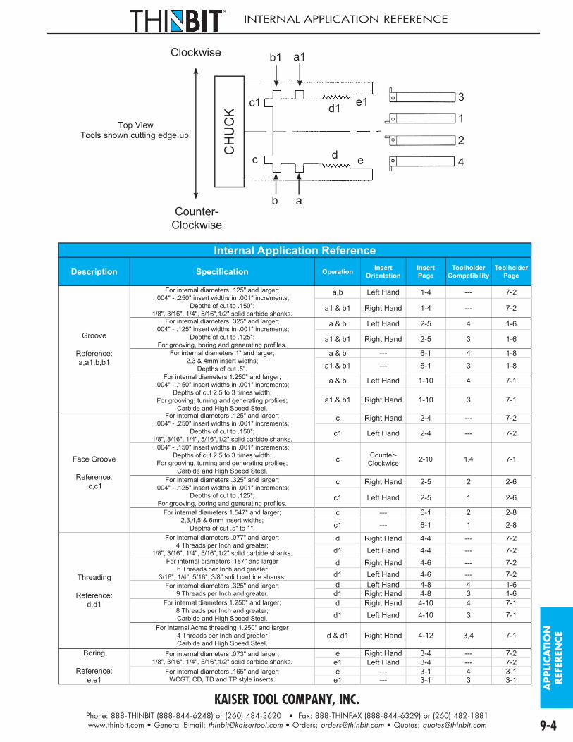
KAISER TOOL COMPANY, INC.Phone: 888-THINBIT (888-844-6248) or (260) 484-3620 • Fax: 888-THINFAX (888-844-6329) or (260) 482-1881www.thinbit.com • General E-mail: [email protected] • Orders: [email protected] • Quotes: [email protected] 9-4
APPLI
CA
TIO
N
REF
EREN
CE
INTERNAL APPLICATION REFERENCE
Counter-Clockwise
Clockwise
a
a1
b
c
c1
b1
d1 e1
d e 4
1
3
2
CH
UC
K
Top ViewTools shown cutting edge up.
Internal Application Reference
Description Specifi cation Operation InsertOrientation
InsertPage
ToolholderCompatibility
ToolholderPage
Groove
Reference:a,a1,b,b1
For internal diameters .125" and larger;.004" - .250" insert widths in .001" increments;
Depths of cut to .150";1/8", 3/16", 1/4", 5/16",1/2" solid carbide shanks.
a,b Left Hand 1-4 --- 7-2
a1 & b1 Right Hand 1-4 --- 7-2
For internal diameters .325" and larger;.004" - .125" insert widths in .001" increments;
Depths of cut to .125";For grooving, boring and generating profi les.
a & b Left Hand 2-5 4 1-6
a1 & b1 Right Hand 2-5 3 1-6
For internal diameters 1" and larger;2,3 & 4mm insert widths;
Depths of cut .5".
a & b --- 6-1 4 1-8a1 & b1 --- 6-1 3 1-8
For internal diameters 1.250" and larger;.004" - .150" insert widths in .001" increments;
Depths of cut 2.5 to 3 times width;For grooving, turning and generating profi les;
Carbide and High Speed Steel.
a & b Left Hand 1-10 4 7-1
a1 & b1 Right Hand 1-10 3 7-1
Face Groove
Reference: c,c1
For internal diameters .125" and larger;.004" - .250" insert widths in .001" increments;
Depths of cut to .150";1/8", 3/16", 1/4", 5/16",1/2" solid carbide shanks.
c Right Hand 2-4 --- 7-2
c1 Left Hand 2-4 --- 7-2
.004" - .150" insert widths in .001" increments;Depths of cut 2.5 to 3 times width;
For grooving, turning and generating profi les;Carbide and High Speed Steel.
c Counter-Clockwise 2-10 1,4 7-1
For internal diameters .325" and larger;.004" - .125" insert widths in .001" increments;
Depths of cut to .125";For grooving, boring and generating profi les.
c Right Hand 2-5 2 2-6
c1 Left Hand 2-5 1 2-6
For internal diameters 1.547" and larger;2,3,4,5 & 6mm insert widths;
Depths of cut .5" to 1".
c --- 6-1 2 2-8c1 --- 6-1 1 2-8
Threading
Reference:d,d1
For internal diameters .077" and larger;4 Threads per Inch and greater;
1/8", 3/16", 1/4", 5/16",1/2" solid carbide shanks.
d Right Hand 4-4 --- 7-2d1 Left Hand 4-4 --- 7-2
For internal diameters .187" and larger6 Threads per Inch and greater
3/16", 1/4", 5/16", 3/8" solid carbide shanks.
d Right Hand 4-6 --- 7-2d1 Left Hand 4-6 --- 7-2
For internal diameters .325" and larger;9 Threads per Inch and greater.
d Left Hand 4-8 4 1-6d1 Right Hand 4-8 3 1-6
For internal diameters 1.250" and larger;8 Threads per Inch and greater;Carbide and High Speed Steel.
d Right Hand 4-10 4 7-1d1 Left Hand 4-10 3 7-1
For internal Acme threading 1.250" and larger4 Threads per Inch and greaterCarbide and High Speed Steel.
d & d1 Right Hand 4-12 3,4 7-1
Boring
Reference:e,e1
For internal diameters .073" and larger;1/8", 3/16", 1/4", 5/16",1/2" solid carbide shanks.
e Right Hand 3-4 --- 7-2e1 Left Hand 3-4 --- 7-2
For internal diameters .165" and larger;WCGT, CD, TD and TP style inserts.
e --- 3-1 4 3-1e1 --- 3-1 3 3-1

KAISER TOOL COMPANY, INC.Phone: 888-THINBIT (888-844-6248) or (260) 484-3620 • Fax: 888-THINFAX (888-844-6329) or (260) 482-1881www.thinbit.com • General E-mail: [email protected] • Orders: [email protected] • Quotes: [email protected]
INSERT GRADE INFORMATION
DURA-MAX®
2000 CARBIDE
DURA-MAX® 2000 is a versatile and tough sub-micron grain carbide. Because of its high transverse rupture strength and fine grain structure, DURA-MAX® 2000 performs well with interrupted cuts. This grade is recommended for cutting steel, cast iron, stainless steel and applications where there are interrupted cuts.
DURA-MAX® 2000 approximates an ANSI C4/C5.
DURA-MAX®
3000 CARBIDE
DURA-MAX® 3000 is a hard and wear resistant sub-micron grain carbide. DURA-MAX® 3000 is designed for light finish cuts. This grade is recommended for cutting steels and applications where precision finish cuts are required.
DURA-MAX® 3000 approximates an ANSI C7/C8.
DURA-MAX® 3000 inserts are only available on MINI-BORE® style inserts. See Section 3 of this catalog for further detail.
DURA-MAX®
4000 CARBIDE
DURA-MAX® 4000 is a tough, general purpose sub-micron grain carbide. DURA-MAX® 4000 is designed for roughing. This grade is recommended for cutting steels, stainless steel, nickel based alloys and applications where there are interrupted cuts.
DURA-MAX® 4000 approximates an ANSI C5/C6.
DURA-MAX® 4000 inserts are only available on MINI-BORE® style inserts. See Section 3 of this catalog for further detail.
DURA-MAX®
5000 CARBIDE
DURA-MAX® 5000 is a hard, abrasion resistant, sub-micron grain carbide. Because of its hardness and fine grain structure, DURA-MAX® 5000 provides excellent edge and corner retention. This grade is recommended for cutting abrasive materials, non-ferrous alloys, aluminum, plastic and applications where there are no interrupted cuts.
DURA-MAX® 5000 approximates an ANSI C2/C3.
DURA-MAX®
8000 CBN
DURA-MAX® 8000 is a CBN tipped insert which provides an increased production rate, improved surface finish and dimensional control when used on high-temperature alloys such as inconel, nickel base alloys and materials with a hardness of Rockwell C-35 or harder.
DURA-MAX® 8000 CBN tipped inserts are only available on MINI-BORE® style inserts. See Section 3 of this catalog for further detail.
DURA-MAX®
9000 PCD
DURA-MAX® 9000 is a PCD tipped insert which provides an increased production rate, improved surface finish and dimensional control when used on non-ferrous and abrasive metals such as aluminum, brass and copper.
DURA-MAX® 9000 PCD tipped inserts are only available on MINI-BORE® style inserts. See Section 3 of this catalog for further detail.
HIGH SPEED STEEL
High Speed Steel will cut most materials. It will take considerable abuse. However, high speed steel will not wear as well as carbide. We suggest the use of high speed steel for jobs of 500 cuts or less. It also works well on older machines which do not have high enough spindle speeds to take advantage of carbide.
High Speed Steel is an M42 grade.
9-5

KAISER TOOL COMPANY, INC.Phone: 888-THINBIT (888-844-6248) or (260) 484-3620 • Fax: 888-THINFAX (888-844-6329) or (260) 482-1881www.thinbit.com • General E-mail: [email protected] • Orders: [email protected] • Quotes: [email protected] 9-6
GRA
DE
&
CO
ATI
NG
INSERT COATING INFORMATION
TIN(TITANIUM NITRIDE)
Excellent general purpose PVD coating for most applications. TiN offers excellent wear resistance and allows
10% - 30% increase in speeds and feeds. TiN also increases lubricity at cutting edge which reduces galling and welding. TiN is not recommended for Nickel alloys or Titanium.
Color: Yellow/gold
Thickness: 2-4 microns (.0001"-.0002")
TICN(TITANIUM
CARBONITRIDE)
A multi-layer, PVD coating good for cutting Aluminum, Brass, Bronze, Copper and its alloys and Cast Iron. TiCN improves tool life and allows increased speeds and feeds. Should out-perform TiN in abrasive and difficult to machine materials. TiCN is harder and more impact resistant than TiN.
Color: Gray/bronze
Thickness: 2-6 microns (.0001"-.0004")
TIAIN(TITANIUM ALUMINUM
NITRIDE)
A high performance PVD coating which excels in cutting abrasive or difficult-to-machine materials such as Titanium, Inconel, Waspaloy, Hastelloy, High Nickel Alloys, harder varieties of Stainless Steel. Good performance with interrupted cuts, high temperatures and dry machining.
Color: Dark gray/black
Thickness: 2-4 microns (.0001"-.0002")
DIAMOND
Works well in cutting Aircraft Aluminum, Automotive Cast Aluminum, Copper, Brass, Graphite, Carbon, Various Plastics, Nylon, Natural Wood, Composite Woods and Kurtzite. Diamond coating is not recommended for cutting steels or other ferrous metals.
Color: Silver
Thickness: 2-6 microns (.0001"-.0004")
Note on coolants:THINBIT® inserts are compatible with all coolant types. Carbide and High Speed Steel give best performance on most materials when run fl ooded with coolant. Carbide does not perform well in thermal shock situations. Keep insert fl ooded or run dry.
Note on coatings:Part numbers may not always include coating designation.

KAISER TOOL COMPANY, INC.Phone: 888-THINBIT (888-844-6248) or (260) 484-3620 • Fax: 888-THINFAX (888-844-6329) or (260) 482-1881www.thinbit.com • General E-mail: [email protected] • Orders: [email protected] • Quotes: [email protected]
TROUBLESHOOTING INFORMATION
It is critical for small tooling to have correct set ups. Speeds and feeds, condition of toolholder, insert and machine, centerline heights, squareness of cutting edge to machine, rigid machine to toolholder relationships are vital for proper performance in all applications. The items listed are general guides, but will not solve all problems. Please call our sales offi ce for additional assistance.
Problem Things to try Grooving
Cutting oversized;Groove walls not square Check insert squareness; Check toolholder condition; Check insert centerline; Check machine alignment; Decrease IPR
Chatter;Poor fi nish
Increase speed; Reduce feed; Check toolholder condition; Check centerline; Stub toolholder and review toolholder size and machine set up for maximum rigidity; Add coating; Add top rake
Built up edge;Insert chipping Increase feed; Increase speed; Run with coolant; Use coated insert; Check insert centerline
Burr on part Add chamfer to insert; Turn or bore diameter after groove
Insert breaking Check insert squareness; Check toolholder condition; Check insert centerline; Check machine condition; Decrease IPR; Review speeds and feeds; Verify insert grade
Chip control Increase feed; Use peck cycle; Mount with cutting edge down; Flood with coolant; Add chip control to insert
Face GroovingCutting oversized;Groove walls not square Check insert squareness; Check toolholder condition; Check insert centerline; Check machine alignment; Decrease IPR
Chatter;Poor fi nish
Increase speed; Reduce feed; Check toolholder condition; Check centerline; Stub toolholder and review toolholder size and machine set up for maximum rigidity; Add coating; Add top rake
Built up edge;Insert chipping Increase feed; Increase speed; Run with coolant; Use coated insert; Check insert centerline
Burr on part Add chamfer to insert; Turn or bore diameter after groove
Insert breaking Check insert squareness; Verify clearance diameter; Check insert centerline; Check toolholder condition; Check machine condition; Decrease IPR; Review speeds and feeds; Verify insert grade
Chip control Increase feed; Use peck cycle; Mount with cutting edge down; Flood with coolant; Add chip control to insert
Boring/Turning
Chatter;Poor Finish
Increase speed; Reduce feed; Check toolholder condition; Check centerline; Verify chip evacuation; Verify coolant reaching cutting edge; Stub toolholder and review toolholder size and machine set up for maximum rigidity; Add coating; Add top rake
Built up edge;Insert chipping Increase feed; Increase speed; Increase corner radius; Run with coolant; Use coated insert; Check insert centerline
Insert breaking Check squareness; Verify clearance diameter; Check centerline; Check toolholder condition; Check machine condition; Decrease IPR; Review speeds and feeds; Verify insert grade
Chip control Increase feed; Mount with cutting edge down; Flood with coolant; Add chip control to insert
Threading
Chatter;Poor fi nish
Increase speed; Reduce depth of cut per pass; Check toolholder condition; Check centerline; Verify chip evacuation; Verify coolant reaching cutting edge; Stub toolholder and review toolholder size and machine set up for maximum rigidity; Add coating
Built up edge;Insert chipping
Increase depth of cut per pass; Increase speed; Increase corner radius; Run with coolant; Use coated insert; Check insert centerline
Insert breaking Check squareness; Check centerline; Check toolholder condition; Check machine condition; Decrease depth of cut per pass; Review speeds and feeds; Verify insert grade
PartingInsert leading;Faces not square
Check insert squareness; Check toolholder condition; Check insert centerline; Check machine alignment; Decrease IPR; Add lead angle
Chatter;Poor fi nish
Increase speed; Reduce feed; Check toolholder condition; Check centerline; Stub toolholder and review toolholder size and machine set up for maximum rigidity; Add coating; Add top rake
Built up edge;Insert chipping Increase feed; Increase speed; Run with coolant; Use coated insert; Check insert centerline
Burr on part Chamfer before parting; Add lead angle to drop side of insert
Insert breaking Check insert squareness; Check toolholder condition; Check insert centerline; Check machine condition; Decrease IPR; Review speeds and feeds; Verify insert grade
Chip control Increase feed; Use peck cycle; Mount with cutting edge down; Flood with coolant; Add chip control to insert
9-7

KAISER TOOL COMPANY, INC.Phone: 888-THINBIT (888-844-6248) or (260) 484-3620 • Fax: 888-THINFAX (888-844-6329) or (260) 482-1881www.thinbit.com • General E-mail: [email protected] • Orders: [email protected] • Quotes: [email protected] 9-8
GENERAL TOOLHOLDER INFORMATION
EXTENSIONRATIO
Extension RatiosBar Steel Heavy Metal Carbide Shank
SteelDiameter 4 x ø 6 x ø 8 x ø Height
.156" .625" .937" 1.250" .312" 1.250"
.187" .750" 1.125" 1.500" .375" 1.500"
.250" 1.000" 1.500" 2.000" .500" 2.000"
.312" 1.250" 1.875" 2.500" .625" 2.500"
.375" 1.500" 2.250" 3.000" .750" 2.500"
.500" 2.000" 3.000" 4.000" 1.000" 2.500"
.625" 2.500" 3.750" 5.000" 1.250" 2.500"
.750" 3.000"1.000" 4.000"
Extending a toolholder beyond these
recommendations can cause excessive defl ection which will result in poor surface
fi nish and reduced insert life.These recommendations
may need to be reduced if cutting materials with low
machinability, taking heavy cuts or using the tooling in non-rigid machine set-ups.
Toolholder Notes:• To avoid burrs on your shanks, use only dog point screws. The use of cup point screws promotes burrs on the shanks and can result in problems removing or re-installing bars.• Complete toolholders may be an assembly of several components each having an individual part number. • Heavy Metal is a high density Tungsten based alloy that is very tough, stiff and vibration resistant.
INTERNAL TOOL & FACE GROOVING CUTTING HEIGHTS
A
B
C
Diameter is undersizeDiameter is on size
Diameter is oversize
Centerline
• Normal cutting forces cause tool defl ection, therefore internal tools are manufactured to cut .002" to .010" above centerline.• Setting tool above 'A' will cause diameter to be under desired size.• Setting tool to cut at 'A' will cause insert to defl ect to 'B' and cut desired diameter.• Setting tool below 'A' will cause insert to defl ect to 'C' and cause diameter to be oversized.• Keep in mind if tools are mounted cutting edge toward fl oor, above center is toward fl oor.
EXTERNAL TOOL CUTTING HEIGHTS
A
BC
Centerline
• External tools are manufactured to cut on center to .005" below centerline.• Setting tool to cut at 'A' can cause heel of insert to rub or cause failure.• Setting tool to cut at 'B' will cause insert to defl ect slightly and cut at 'C'.• Setting tool below 'C' can cause insert to grab or fail.• Keep in mind if tools are mounted cutting edge toward fl oor, below center is toward ceiling.
DEEPGROOVE® Head and Shank Compatibility Chart
Shank Package Page Head Clamp Shank Package Page Head Clamp Shank Package Page Head Clamp
DGS_ _XLC 2-16 DGH4 DGC2
DGS_ _XRB 2-16 DGH3 DGC1
DGS_ _ZRN 2-8 DGH6 DGC6
E 1-14 DGH2 DGC2 F 1-14 DGH1 DGC1 O 7-13 DGH3 DGC1S 7-14 DGH5 DGC5 T 7-14 DGH6 DGC6 Q 7-13 DGH1 DGC1
DGS_ _YRD 2-16 DGH4 DGC2
DGS_ _YLA 2-16 DGH3 DGC1
DGS_ _ZLM 2-8 DGH5 DGC5
G 1-14 DGH2 DGC2 H 1-14 DGH1 DGC1 P 7-13 DGH4 DGC2U 7-14 DGH5 DGC5 V 7-14 DGH6 DGC6 R 7-13 DGH2 DGC2
TRO
UBLE
SH
OO
TIN
G
& T
OO
LHO
LDER
S
A
CB
ABC

KAISER TOOL COMPANY, INC.Phone: 888-THINBIT (888-844-6248) or (260) 484-3620 • Fax: 888-THINFAX (888-844-6329) or (260) 482-1881www.thinbit.com • General E-mail: [email protected] • Orders: [email protected] • Quotes: [email protected]
GROOVING INFORMATION
O D
G D
G W
D S
2.Example: 1" outer diameter with .75" groove diameter.1"-.75" = .125" depth of cut 2
Setu
p G
uide
External Grooving ApplicationsDecrease surface speed (SFM)
Increase feed (IPR)Set tool on center to .005" below center. Keep smaller inserts closer to center.
Insert width: .004" .020" .040" .060" .080" .100" .120" .140" .160" .180" .200" .220" .250"
Internal Grooving ApplicationsDecrease surface speed (SFM)
Increase feed (IPR)Set tool .002" to .010" above center. Keep smaller inserts closer to center.
B D
G D
G W
D B
D S
2.
Example: 1" groove diameter with .75" bore diameter.1"-.75" = .125" depth of cut 2Insert begins
with:LGT, MGTI, GT
Insert begins with:
DGI, DGMI
1 2 CA B
Cutting PathsUse these diagrams for expanding the size of grooves.
Note: Side load on path 1 should be 10% to 30% of depth of cut on insert.
Modify Parameter
Modify Parameter
9-9

KAISER TOOL COMPANY, INC.Phone: 888-THINBIT (888-844-6248) or (260) 484-3620 • Fax: 888-THINFAX (888-844-6329) or (260) 482-1881www.thinbit.com • General E-mail: [email protected] • Orders: [email protected] • Quotes: [email protected] 9-10
GRO
OV
ING
Speeds & Feeds - Grooving
Material To Be CutCarbide High Speed Steel
CarbideGrade
Speed(SFM)
Feed(IPR)
Speed(SFM)
Feed(IPR)
Aluminum 2021-6061 DURA-MAX® 5000 1000 .002 500 .002
Brass DURA-MAX® 5000 250 .001 75 .001
Bronze DURA-MAX® 5000 250 .001 70 .001
Cast Iron
Gray DURA-MAX® 5000 120-345 .0015-.004 35-125 .0015-.004
Ductile DURA-MAX® 2000 70-345 .001-.004 15-125 .001-.004
Malleable DURA-MAX® 2000 75-525 .0015-.003 35-170 .0015-.003
Copper101-757 DURA-MAX® 5000 150-170 .002 85-90 .002
834-978 DURA-MAX® 5000 600 .003 340 .003
Magnesium AZ, AM, EZ, ZE, HK Types DURA-MAX® 5000 1000 .002 500 .002
Nickel
Nickel 200-230 DURA-MAX® 5000 225 .002 85 .002
Monel DURA-MAX® 5000 150 .001-.0015 15-60 .001-.0015
Inconel, Waspaloy DURA-MAX® 5000 45 .002 15 .002
Hastelloy DURA-MAX® 5000 75-95 .002 10-15 .002
Plastic
Tefl on (TFE, CTFE) DURA-MAX® 5000 400 .002 250 .002
Nylon DURA-MAX® 5000 350-600 .002-.003 350 .002-.003
Phenolic DURA-MAX® 5000 600 .003 350 .003
Glass Filled DURA-MAX® 5000 250 .002 NA NA
Stainless Steel
201-385 DURA-MAX® 5000 225-275 .001-.0015 65-85 .001-.0015
405-446 DURA-MAX® 2000 300 .0011 90 .0011
14-4, 15-5, 16-6, 17-4 PH DURA-MAX® 2000 110-205 .0006-.0012 30-60 .0006-.0012
Steel
1005-1029 DURA-MAX® 2000 255-450 .001-.002 80-140 .001-.002
1030-1055 DURA-MAX® 2000 115-370 .0009-.0015 35-115 .0009-.0015
1060-1095 DURA-MAX® 2000 95-255 .0007-.001 30-80 .0007-.001
10L45-10L50 DURA-MAX® 2000 130-450 .0009-.0015 40-140 .0009-.0015
12L13-12L15 DURA-MAX® 2000 550-600 .003-.0035 225-280 .003-.0035
41L30-41L50 DURA-MAX® 2000 65-350 .0007-.0015 20-110 .0007-.0015
4140-4150 DURA-MAX® 2000 65-370 .0007-.0015 20-115 .0007-.0015
4140 (35 HRc) DURA-MAX® 2000 200 .001 70 .001
8617-8622 DURA-MAX® 2000 125-390 .001-.0016 40-120 .001-.0016
M1-M6 DURA-MAX® 2000 190 .0013 60 .0013
H10-H19 DURA-MAX® 2000 65-255 .0007-.0011 20-80 .007-.0011
D2-D7 DURA-MAX® 2000 150-205 .001 45-60 .001
A2-A9, 01-07 DURA-MAX® 2000 150-205 .001 45-60 .001
W1, W2 DURA-MAX® 2000 375 .0015 110 .0015
M-50, 52100 DURA-MAX® 2000 65-275 .0007-.0015 20-85 .0007-.0015
Titanium Ti-6Al-6V DURA-MAX® 5000 95 .001 45 .001
THESE SPEEDS AND FEEDS ARE GIVEN AS A STARTING POINT ONLY AND MAY BE ADJUSTED UP OR DOWN DEPENDING ON CONDITIONS. ANY TIME THERE IS AN INTERRUPTED CUT IN YOUR OPERATION, DURA-MAX® 2000 CARBIDE IS RECOMMENDED.
FORMULA FOR CONVERSION FROM SFM TO RPMSFM = SURFACE FEET PER MINUTE RPM = REVOLUTIONS PER MINUTE IPR = INCHES PER REVOLUTION DIAMETER = CUTTING DIAMETER = 3.14
SFM X 12 (π) X DIAMETER
RPM =

KAISER TOOL COMPANY, INC.Phone: 888-THINBIT (888-844-6248) or (260) 484-3620 • Fax: 888-THINFAX (888-844-6329) or (260) 482-1881www.thinbit.com • General E-mail: [email protected] • Orders: [email protected] • Quotes: [email protected]
FACE GROOVING INFORMATION
MD
M D
M D
D C
G WS
2.
Example: 1" major diameter with .75" minor diameter.1"-.75" = .125" Groove Width 2
Setu
p G
uide
External Face Grooving ApplicationsDecrease surface speed (SFM)
Increase feed (IPR)Set tool on .002" to .010" above center. Keep smaller inserts closer to center.
Insert width: .004" .020" .040" .060" .080" .100" .120" .140" .160" .180" .200" .220" .250"
Internal Face Grooving ApplicationsDecrease surface speed (SFM)
Increase feed (IPR)Set tool .002" to .010" above center. Keep smaller inserts closer to center.
D C
B D
MD
M D
G WS
2.
Example: 1" major diameter with .75" minor diameter.1"-.75" = .125" Groove Width 2
Insert begins with:
LGT, MGTI, FT
Insert begins with:
DGI, DGMI
1 2 CA B
Cutting PathsUse these diagrams for expanding the size of grooves.
Note: Side load on path 1 should be 10% to 30% of depth of cut on insert.
D C
D
B
Modify Parameter
Modify Parameter
9-11

KAISER TOOL COMPANY, INC.Phone: 888-THINBIT (888-844-6248) or (260) 484-3620 • Fax: 888-THINFAX (888-844-6329) or (260) 482-1881www.thinbit.com • General E-mail: [email protected] • Orders: [email protected] • Quotes: [email protected] 9-12
FACE
GRO
OV
ING
Speeds & Feeds - Face Grooving
Material To Be CutCarbide High Speed Steel
CarbideGrade
Speed(SFM)
Feed(IPR)
Speed(SFM)
Feed(IPR)
Aluminum 2021-6061 DURA-MAX® 5000 1000 .002-.003 525 .002-.003
Brass DURA-MAX® 5000 250 .001 75 .001
Bronze DURA-MAX® 5000 250 .001 70 .001
Cast IronGray DURA-MAX® 5000 300-500 .0017-.0027 35-115 .0017-.0027
Ductile DURA-MAX® 2000 250-425 .0013-.0027 30-75 .0013-.0027
Malleable DURA-MAX® 2000 300-600 .0013-.0027 35-120 .0013-.0027
Copper101-757 DURA-MAX® 5000 450-550 .002 80-90 .0013-.0017
834-978 DURA-MAX® 5000 600 .003 325 .0017
Magnesium AZ, AM, EZ, ZE, HK Types DURA-MAX® 5000 1000 .001-.002 650 .001-.002
Nickel
Nickel 200-230 DURA-MAX® 5000 225 .002 80 .001
Monel DURA-MAX® 5000 45-150 .001-.002 40-55 .001-.002
Inconel, Waspaloy DURA-MAX® 5000 75-100 .0013 10 .001
Hastelloy DURA-MAX® 5000 100-125 .0013-.0017 10-15 .001-.0015
Plastic
Tefl on (TFE, CTFE) DURA-MAX® 5000 400 .003 250 .003
Nylon DURA-MAX® 5000 350-600 .002-.003 350 .002-.003
Phenolic DURA-MAX® 5000 600 .003 350 .003
Glass Filled DURA-MAX® 5000 250 .002 N/A N/A
Stainless Steel201-385 DURA-MAX® 5000 225-275 .0013-.002 60-65 .001
405-446 DURA-MAX® 2000 275 .002 90 .001
14-4, 15-5, 16-6, 17-4 PH DURA-MAX® 2000 125-150 .0013-.002 40-50 .001
Steel
1005-1029 DURA-MAX® 2000 400-500 .002-.003 75-110 .002-.003
1030-1055 DURA-MAX® 2000 325-450 .0013-.0027 30-85 .0013-.0027
1060-1095 DURA-MAX® 2000 325-400 .0016-.0027 30-70 .0016-.0027
10L45-10L50 DURA-MAX® 2000 300-600 .0017-.0027 35-130 .0017-.0027
12L13-12L15 DURA-MAX® 2000 500-600 .002-.003 105-130 .002-.003
41L30-41L50 DURA-MAX® 2000 325-500 .0013-.0027 30-105 .0013-.0027
4140-4150 DURA-MAX® 2000 325-450 .0013-.0027 30-95 .0013-.0027
4140 (35 HRc) DURA-MAX® 2000 350 .0013 45 .0013
8617-8622 DURA-MAX® 2000 250-475 .001-.0023 30-90 .001-.0023
M1-M6 DURA-MAX® 2000 350 .002 50 .001
H10-H19 DURA-MAX® 2000 300-425 .001-.002 35-75 .001-.002
D2-D7 DURA-MAX® 2000 300-375 .002 35-60 .0015-.002
A2-A9, 01-07 DURA-MAX® 2000 300-375 .002 35-60 .0015-.002
W1, W2 DURA-MAX® 2000 425 .002 75 .002
M-50, 52100 DURA-MAX® 2000 350 .002 55 .002
Titanium Ti-6Al-6V DURA-MAX® 5000 95 .001 40 .002
THESE SPEEDS AND FEEDS ARE GIVEN AS A STARTING POINT ONLY AND MAY BE ADJUSTED UP OR DOWN DEPENDING ON CONDITIONS. ANY TIME THERE IS AN INTERRUPTED CUT IN YOUR OPERATION, DURA-MAX® 2000 CARBIDE IS RECOMMENDED.
FORMULA FOR CONVERSION FROM SFM TO RPMSFM = SURFACE FEET PER MINUTE RPM = REVOLUTIONS PER MINUTE IPR = INCHES PER REVOLUTION DIAMETER = CUTTING DIAMETER = 3.14
SFM X 12 (π) X DIAMETER
RPM =

KAISER TOOL COMPANY, INC.Phone: 888-THINBIT (888-844-6248) or (260) 484-3620 • Fax: 888-THINFAX (888-844-6329) or (260) 482-1881www.thinbit.com • General E-mail: [email protected] • Orders: [email protected] • Quotes: [email protected]
BORING & TURNING INFORMATION
O D
W D
F D
D CS
2.Example: 1" outer diameter with .976" working diameter.1"-.976" = .012" depth of cut 2
Setu
p G
uide
Turning ApplicationsDecrease surface speed (SFM)
Increase feed (IPR)Increase depth of cut
Set tool on center to .005" below center. Keep smaller inserts closer to center.
MBZ MBA MBE MBB MBF MBC MBG
Tool starts with: BT21 BT31 BT41 BT51 BT61 BT81
Boring ApplicationsDecrease surface speed (SFM)
Increase feed (IPR)Increase depth of cut
Set tool .002" to .010" above center. Keep smaller tools closer to center.
B D
W D
D B
FD
D CS
2.Example: 1" working diameter with .976" bore diameter.1"-.976" = .012" depth of cut 2
Cutting Paths: •Internal tools designed for feeding into bore. •External tools designed for feeding toward chuck.N PS
2 .
Example: 1" outer diameter with .875" fi nish diameter and .012" per pass.1"-.875" = 5.2 or 6 passes 2 x .012"Note: Leave 30% - 50% of depth of cut for fi nish pass.
Modify Parameter
Modify Parameter
9-13

KAISER TOOL COMPANY, INC.Phone: 888-THINBIT (888-844-6248) or (260) 484-3620 • Fax: 888-THINFAX (888-844-6329) or (260) 482-1881www.thinbit.com • General E-mail: [email protected] • Orders: [email protected] • Quotes: [email protected] 9-14
BO
RIN
G
Speeds & Feeds - MBE, MBF & MBG Style Inserts
Material To Be Cut CarbideGrade
Speed(SFM)
Feed(IPR)
Depth of Cut
MBE MBF MBG
Aluminum 2021-6061 DURA-MAX® 5000 450-1000 .005-.012 .012 .014 .016
Brass DURA-MAX® 5000 300-400 .002-.005 .010 .010 .012
Bronze DURA-MAX® 5000 300-400 .002-.005 .009 .010 .012
Cast IronGray DURA-MAX® 5000 200-300 .005-.010 .010 .012 .015
Ductile DURA-MAX® 4000 200-300 .005-.010 .010 .012 .015
Malleable DURA-MAX® 4000 100-300 .005-.010 .010 .012 .015
Copper101-757 DURA-MAX® 4000 400-750 .003-.005 .012 .014 .016
834-978 DURA-MAX® 5000 300-700 .003-.005 .012 .014 .016
Magnesium AZ, AM, EZ, ZE, HK Types DURA-MAX® 5000 700-1300 .005-.012 .012 .014 .016
Nickel
Nickel 200-230 DURA-MAX® 4000 100-250 .002-.005 .008 .008 .008
Monel DURA-MAX® 4000 80-120 .0005-.001 .008 .008 .008
Inconel, Waspaloy DURA-MAX® 4000 70-95 .001-.003 .008 .008 .008
Hastelloy DURA-MAX® 4000 50-80 .001-.003 .008 .008 .008
Plastic
Tefl on (TFE, CTFE) DURA-MAX® 5000 500-850 .004-.008 .010 .012 .015
Nylon DURA-MAX® 5000 700-1000 .002-.005 .010 .012 .015
Phenolic DURA-MAX® 5000 700-1000 .005 .010 .012 .015
Glass Filled DURA-MAX® 5000 700-1000 .005 .008 .012 .015
Stainless Steel201-385 DURA-MAX® 4000 100-225 .002-.004 .009 .010 .012
405-446 DURA-MAX® 4000 100-225 .002-.004 .008 .009 .010
14-4, 15-5, 16-6, 17-4 PH DURA-MAX® 4000 300-400 .002-.004 .008 .009 .010
Steel
1005-1029 DURA-MAX® 4000 100-250 .003-.007 .010 .012 .015
1030-1055 DURA-MAX® 4000 100-250 .003-.007 .010 .012 .015
1060-1095 DURA-MAX® 4000 100-350 .003-.007 .010 .012 .015
10L45-10L50 DURA-MAX® 4000 250-450 .006-.008 .010 .012 .015
12L13-12L15 DURA-MAX® 4000 250-450 .004-.006 .010 .012 .015
41L30-41L50 DURA-MAX® 4000 150-350 .003-.007 .010 .012 .015
4140-4150 DURA-MAX® 4000 100-350 .003-.007 .010 .012 .015
4140 (35 HRc) DURA-MAX® 4000 90-125 .003-.007 .008 .008 .010
8617-8622 DURA-MAX® 4000 100-200 .004-.008 .010 .012 .015
M1-M6 DURA-MAX® 4000 100-200 .004-.008 .008 .010 .012
H10-H19 DURA-MAX® 4000 100-200 .004-.008 .008 .010 .012
D2-D7 DURA-MAX® 4000 100-200 .004-.008 .008 .010 .012
A2-A9, 01-07 DURA-MAX® 4000 100-200 .004-.008 .008 .010 .012
W1, W2 DURA-MAX® 4000 100-200 .004-.008 .008 .010 .012
M-50, 52100 DURA-MAX® 4000 200-300 .005-.010 .010 .012 .015
Titanium Ti-6Al-6V DURA-MAX® 5000 90-250 .001-.003 .008 .009 .010
THESE SPEEDS AND FEEDS ARE GIVEN AS A STARTING POINT ONLY AND MAY BE ADJUSTED UP OR DOWN DEPENDING ON CONDITIONS. ANY TIME THERE IS AN INTERRUPTED CUT IN YOUR OPERATION, DURA-MAX® 4000 CARBIDE IS RECOMMENDED.
FORMULA FOR CONVERSION FROM SFM TO RPMSFM = SURFACE FEET PER MINUTE RPM = REVOLUTIONS PER MINUTE IPR = INCHES PER REVOLUTION DIAMETER = CUTTING DIAMETER = 3.14
SFM X 12 (π) X DIAMETER
RPM =

KAISER TOOL COMPANY, INC.Phone: 888-THINBIT (888-844-6248) or (260) 484-3620 • Fax: 888-THINFAX (888-844-6329) or (260) 482-1881www.thinbit.com • General E-mail: [email protected] • Orders: [email protected] • Quotes: [email protected]
Speeds & Feeds - MBZ, MBA, MBB, MBC Style Inserts & MICROBIT ® Solid Carbide Tools
Material To Be Cut
CarbideGrade Depth of Cut
MBA,MBB,MBC,MBZ Speed(SFM)
Feed(IPR)
MBA, MBZ
BT2, BT3
MBB,BT4,BT5
MBC,BT6, BT8
Aluminum 2021-6061 DURA-MAX® 5000 700-1400 .005-.012 .008 .008 .016
Brass DURA-MAX® 5000 350-400 .001-.003 .006 .006 .012
Bronze DURA-MAX® 5000 300-400 .001-.002 .006 .006 .012
Cast IronGray DURA-MAX® 5000 250-350 .004-.010 .007 .007 .015
Ductile DURA-MAX® 5000 250-350 .004-.010 .007 .007 .015
Malleable DURA-MAX® 5000 250-350 .004-.010 .007 .007 .015
Copper101-757 DURA-MAX® 5000 600-800 .003-.005 .008 .008 .016
834-978 DURA-MAX® 5000 600-800 .003-.005 .008 .008 .016
Magnesium AZ, AM, EZ, ZE, HK Types DURA-MAX® 5000 750-1500 .005-.012 .008 .008 .016
Nickel
Nickel 200-230 DURA-MAX® 5000 100-250 .002-.005 .004 .004 .008
Monel DURA-MAX® 5000 80-120 .001-.003 .004 .004 .008
Inconel, Waspaloy DURA-MAX® 5000 80-120 .001-.003 .004 .004 .008
Hastelloy DURA-MAX® 5000 80-120 .001-.003 .004 .004 .008
Plastic
Tefl on (TFE, CTFE) DURA-MAX® 5000 500-600 .003-.006 .007 .007 .015
Nylon DURA-MAX® 5000 700-800 .001-.003 .007 .007 .015
Phenolic DURA-MAX® 5000 700-800 .001-.003 .007 .007 .015
Glass Filled DURA-MAX® 5000 700-800 .001-.003 .005 .005 .015
Stainless Steels201-385 DURA-MAX® 5000 100-250 .0015-.004 .005 .005 .010
405-446 DURA-MAX® 5000 100-250 .0015-.004 .005 .005 .010
14-4, 15-5, 16-6, 17-4 PH DURA-MAX® 5000 300-400 .002-.004 .005 .005 .010
Steel
1005-1029 DURA-MAX® 3000/4000 100-300 .003-.007 .007 .007 .015
1030-1055 DURA-MAX® 3000/4000 100-300 .003-.007 .007 .007 .015
1060-1095 DURA-MAX® 3000/4000 150-400 .003-.005 .007 .007 .015
10L45-10L50 DURA-MAX® 3000/4000 300-500 .004-.006 .007 .007 .015
12L13-12L15 DURA-MAX® 3000/4000 300-500 .003-.005 .007 .007 .015
41L30-41L50 DURA-MAX® 3000/4000 200-400 .003-.005 .007 .007 .015
4140-4150 DURA-MAX® 3000/4000 150-400 .003-.005 .007 .007 .015
4140 (35 HRc) DURA-MAX® 3000/4000 90-125 .001-.004 .004 .004 .008
8617-8622 DURA-MAX® 3000/4000 100-300 .002-.004 .007 .007 .015
M1-M6 DURA-MAX® 3000/4000 150-250 .003-.008 .006 .006 .012
H10-H19 DURA-MAX® 3000/4000 150-250 .003-.007 .006 .006 .012
D2-D7 DURA-MAX® 3000/4000 150-250 .004-.010 .006 .006 .012
A2-A9, 01-07 DURA-MAX® 3000/4000 150-250 .003-.008 .006 .006 .012
W1, W2 DURA-MAX® 3000/4000 150-250 .003-.008 .006 .006 .012
M-50, 52100 DURA-MAX® 3000/4000 300-400 .004-.010 .007 .007 .015
Titanium Ti-6Al-6V DURA-MAX® 5000 90-250 .001-.003 .005 .005 .010
THESE SPEEDS AND FEEDS ARE GIVEN AS A STARTING POINT ONLY AND MAY BE ADJUSTED UP OR DOWN DEPENDING ON CONDITIONS. ANY TIME THERE IS AN INTERRUPTED CUT IN YOUR OPERATION, DURA-MAX® 3000/4000 CARBIDE IS RECOMMENDED.
FORMULA FOR CONVERSION FROM SFM TO RPMSFM = SURFACE FEET PER MINUTE RPM = REVOLUTIONS PER MINUTE IPR = INCHES PER REVOLUTION DIAMETER = CUTTING DIAMETER = 3.14
SFM X 12 (p) X DIAMETER
RPM =
9-15

KAISER TOOL COMPANY, INC.Phone: 888-THINBIT (888-844-6248) or (260) 484-3620 • Fax: 888-THINFAX (888-844-6329) or (260) 482-1881www.thinbit.com • General E-mail: [email protected] • Orders: [email protected] • Quotes: [email protected] 9-16
BO
RIN
G
Speeds & Feeds - DURA-MAX® 9000 (PCD Tipped) Insert
Material To Be Cut Speed(SFM)
Feed(IPR)
Depth of Cut
MBA MBB MBCAluminum (High Silicon) 1000-2000 .003-.010 .001-.007 .002-.008 .003-.012Bronze, Brass 800-1500 .003-.010 .001-.007 .002-.008 .003-.012Copper Alloys 800-1200 .003-.010 .001-.007 .002-.008 .003-.012Fiberglass 500-900 .001-.005 .001-.007 .002-.008 .003-.012Green Carbide 500-1400 .001-.004 .001-.007 .002-.008 .003-.012Monel 1000-2000 .003-.010 .001-.007 .002-.008 .003-.012Phenolic 500-900 .001-.005 .001-.007 .002-.008 .003-.012Plastics 500-900 .001-.004 .001-.007 .002-.008 .003-.012
Speeds & Feeds - DURA-MAX® 8000 (CBN Tipped) Insert
Material To Be Cut Speed(SFM)
Feed(IPR)
Depth of Cut
MBA MBB MBC52100 (58-62 HRc) 300-500 .003-.007 .001-.007 .002-.008 .003-.012Hardened Alloy Steel 200-400 .003-.007 .001-.007 .002-.008 .003-.012Hardened High Carbon Steel 300-500 .003-.007 .001-.007 .002-.008 .003-.012Hardened Tool Steel 150-300 .002-.005 .001-.007 .002-.008 .003-.012NI-Hard Cast Iron 100-300 .007-.015 .001-.007 .002-.008 .003-.012Pearlitic Gray Cast Iron 800-1800 .007-.015 .001-.007 .002-.008 .003-.012Powdered Metal 350-500 .003-.007 .001-.007 .002-.008 .003-.012Stellite 100-200 .002-.004 .001-.007 .002-.008 .003-.012Super Alloys 400-900 .003-.007 .001-.007 .002-.008 .003-.012Thermal Spray Co Based 200-600 .002-.005 .001-.007 .002-.008 .003-.012Thermal Spray Ni Based 150-450 .002-.007 .001-.007 .002-.008 .003-.012
THESE SPEEDS AND FEEDS ARE GIVEN AS A STARTING POINT ONLY AND MAY BE ADJUSTED UP OR DOWN DEPENDING ON CONDITIONS. ANY TIME THERE IS AN INTERRUPTED CUT IN YOUR OPERATION, DURA-MAX® 3000 & 4000 CARBIDES ARE RECOMMENDED.
FORMULA FOR CONVERSION FROM SFM TO RPM
SFM = SURFACE FEET PER MINUTE RPM = REVOLUTIONS PER MINUTE IPR = INCHES PER REVOLUTION DIAMETER = CUTTING DIAMETER
π = 3.14
SFM X 12 (π) X DIAMETER
ANSI STANDARD INSERT IDENTIFICATION SYSTEM
References to "insert type" in this catalog are based upon the ANSI B212.4-1995 system. The two letter codes refer to shape and relief angle. The use of four letter codes adds the tolerances and type (or configuration) to the first two letters. Following are the codes used for our inserts:
SHAPE RELIEFANGLE TOLERANCES TYPE
(CONFIGURATION)
C Diamond (80°) C 17° Insert I.C. Thickness B With Hole & Countersink
T Triangle P 11° A +/-.0002" +/-.001D Smaller than .250" I.C.
With HoleW Trigon D 15° C +/-.0005" +/-.001
G +/-.001" +/-.002H Hole, Countersink &
Molded Chipbreaker
G Hole, Countersink &Ground Chipbreaker
T Hole, Countersink &Ground Chipbreaker One Side
RPM =
SHAPE RELIEFANGLE TOLERANCES TYPE
(CONFIGURATION)
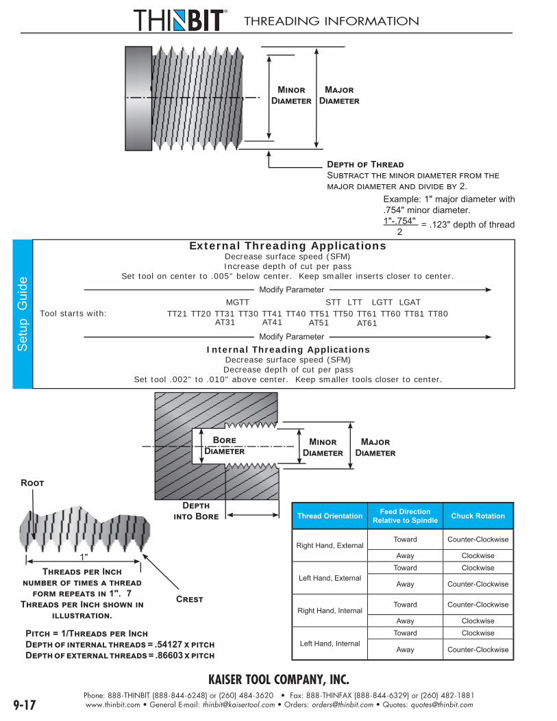
KAISER TOOL COMPANY, INC.Phone: 888-THINBIT (888-844-6248) or (260) 484-3620 • Fax: 888-THINFAX (888-844-6329) or (260) 482-1881www.thinbit.com • General E-mail: [email protected] • Orders: [email protected] • Quotes: [email protected]
THREADING INFORMATION
MD
M D
D TS
2.Example: 1" major diameter with .754" minor diameter.1"-.754" = .123" depth of thread 2
Setu
p G
uide
External Threading ApplicationsDecrease surface speed (SFM)Increase depth of cut per pass
Set tool on center to .005" below center. Keep smaller inserts closer to center.
MGTT STT LTT LGTT LGAT TT21 TT20 TT31 TT30 TT41 TT40 TT51 TT50 TT61 TT60 TT81 TT80Tool starts with:
AT31 AT41 AT51 AT61
Internal Threading ApplicationsDecrease surface speed (SFM)Decrease depth of cut per pass
Set tool .002" to .010" above center. Keep smaller tools closer to center.
M D
M D
D B
B D
1"
C
T I 1". 7
T I .
P = 1/T ID = .54127 D = .86603
Thread Orientation Feed DirectionRelative to Spindle Chuck Rotation
Right Hand, ExternalToward Counter-Clockwise
Away Clockwise
Left Hand, ExternalToward Clockwise
Away Counter-Clockwise
Right Hand, InternalToward Counter-Clockwise
Away Clockwise
Left Hand, InternalToward Clockwise
Away Counter-Clockwise
R
Modify Parameter
Modify Parameter
9-17

KAISER TOOL COMPANY, INC.Phone: 888-THINBIT (888-844-6248) or (260) 484-3620 • Fax: 888-THINFAX (888-844-6329) or (260) 482-1881www.thinbit.com • General E-mail: [email protected] • Orders: [email protected] • Quotes: [email protected] 9-18
THREA
DIN
G
Speeds & Feeds - Threading
Material To Be Cut CarbideGrade
Speed (SFM) Infeed Per Pass (IPR)
Carbide HSS 1st Pass Last Pass
Aluminum 2021-6061 DURA-MAX® 5000 100-200 80-150 .020 .001
Brass DURA-MAX® 5000 200-300 50-150 .010 .001
Bronze DURA-MAX® 5000 200-300 50-150 .010 .001
Cast Iron Gray, Ductile, Malleable DURA-MAX® 2000 85-140 25-50 .015 .0005
Copper 101-757, 834-978 DURA-MAX® 5000 100-200 30-100 .010 .001
Magnesium AZ, AM, EZ, ZE, HK Types DURA-MAX® 5000 100-200 80-150 .020 .001
Nickel Nickel 200-230, Monel, Inconel DURA-MAX® 5000 40-100 20-25 .015 .001
Waspaloy, Hastelloy DURA-MAX® 5000 40-100 20-25 .015 .001
Plastic
Tefl on (TFE, CTFE) DURA-MAX® 5000 250-400 100-300 .015 .001
Nylon DURA-MAX® 5000 250-400 100-300 .015 .001
Phenolic DURA-MAX® 5000 250-400 100-300 .015 .001
Glass Filled DURA-MAX® 5000 250-400 NA .015 .001
Stainless Steel201-385 DURA-MAX® 5000 65-100 8-20 .015 .001
405-446 DURA-MAX® 2000 65-100 8-20 .015 .001
14-4, 15-5, 16-6, 17-4 PH DURA-MAX® 2000 65-100 8-20 .015 .001
Steel
1005-1029, 1030-1055 DURA-MAX® 2000 50-150 30-40 .015 .001
1060-1095, 10L45-10L50 DURA-MAX® 2000 50-150 30-40 .015 .001
12L13-12L15, 41L30-41L50 DURA-MAX® 2000 50-150 30-40 .015 .001
4140-4150, 4140 (35 HRc) DURA-MAX® 2000 50-150 30-40 .015 .001
8617-8622, M1-M6 DURA-MAX® 2000 50-150 30-40 .015 .001
D2-D7, A2-A9, 01-07 DURA-MAX® 2000 50-150 30-40 .015 .001
W1, W2, M-50, 52100 DURA-MAX® 2000 50-150 30-40 .015 .001
Titanium Ti-6Al-6V DURA-MAX® 5000 40-65 5-9 .020 .0005
Single Point Threading - Roughing Infeed Depth per Pass
(Based on Equal Areas of Material Removal per Pass)
Pass Threads Per Inch8 10 11 12 13 14 16 18 20 24 28 32 36 40
1st .017 .015 .013 .013 .012 .011 .011 .011 .010 .009 .008 .008 .007 .0082nd .028 .024 .022 .022 .020 .019 .018 .018 .016 .015 .013 .013 .011 .0133rd .037 .032 .029 .029 .026 .024 .023 .023 .021 .019 .016 .017 .0154th .045 .038 .035 .035 .032 .029 .028 .028 .025 .023 .0195th .052 .044 .040 .040 .036 .034 .032 .032 .0286th .058 .049 .045 .044 .041 .038 .0367th .064 .054 .049 .049 .045 .0418th .069 .059 .0539th .074
THESE SPEEDS AND FEEDS ARE GIVEN AS A STARTING POINT ONLY AND MAY BE ADJUSTED UP OR DOWN DEPENDING ON CONDITIONS. ANY TIME THERE IS AN INTERRUPTED CUT IN YOUR OPERATION, DURA-MAX® 2000 CARBIDE IS RECOMMENDED.
FORMULA FOR CONVERSION FROM SFM TO RPMSFM = SURFACE FEET PER MINUTE RPM = REVOLUTIONS PER MINUTE IPR = INCHES PER REVOLUTION DIAMETER = CUTTING DIAMETER π3.14
SFM X 12 (π) X DIAMETERRPM =
Note: One or more finish passes will be necessary to finish the thread

KAISER TOOL COMPANY, INC.Phone: 888-THINBIT (888-844-6248) or (260) 484-3620 • Fax: 888-THINFAX (888-844-6329) or (260) 482-1881www.thinbit.com • General E-mail: [email protected] • Orders: [email protected] • Quotes: [email protected]
PARTING INFORMATION
Depth of Cut to partSolid:Divide outside diameter by 2
Example: 1" outside diameter 1" = .5" depth of cut to part 2
Depth of Cut to partTubing:Subtract inside diameter from outside diameter and divide by 2
Example: 1" outside diameter with .5" inside diameter.1"-.5" = .25" depth of cut to part 2
Setu
p G
uide
External Parting ApplicationsDecrease surface speed (SFM)Increase depth of cut per pass
Set tool on center to .005" below center. Keep smaller inserts closer to center.
Tool starts with: LGPT025 LGPT045 LGPT062 LGPT085 LGPT115 SPT025 SPT045 SPT062 LPT085 LPT115
Modify Parameter
9-19
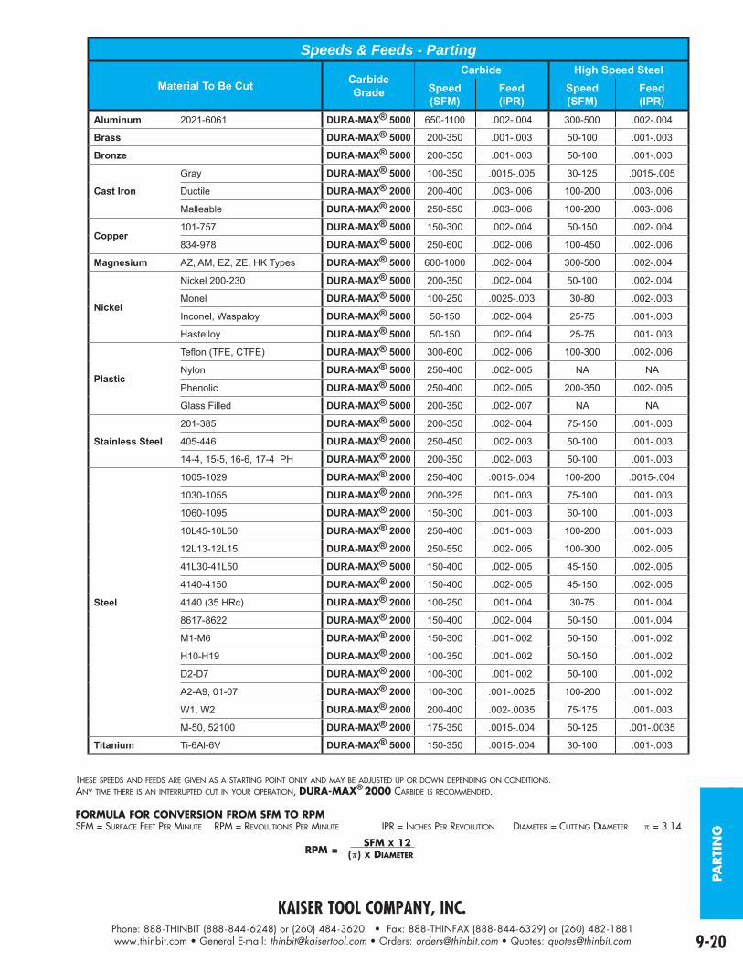
KAISER TOOL COMPANY, INC.Phone: 888-THINBIT (888-844-6248) or (260) 484-3620 • Fax: 888-THINFAX (888-844-6329) or (260) 482-1881www.thinbit.com • General E-mail: [email protected] • Orders: [email protected] • Quotes: [email protected] 9-20
PARTI
NG
Speeds & Feeds - Parting
Material To Be Cut CarbideGrade
Carbide High Speed SteelSpeed(SFM)
Feed(IPR)
Speed(SFM)
Feed(IPR)
Aluminum 2021-6061 DURA-MAX® 5000 650-1100 .002-.004 300-500 .002-.004
Brass DURA-MAX® 5000 200-350 .001-.003 50-100 .001-.003
Bronze DURA-MAX® 5000 200-350 .001-.003 50-100 .001-.003
Cast Iron
Gray DURA-MAX® 5000 100-350 .0015-.005 30-125 .0015-.005
Ductile DURA-MAX® 2000 200-400 .003-.006 100-200 .003-.006
Malleable DURA-MAX® 2000 250-550 .003-.006 100-200 .003-.006
Copper101-757 DURA-MAX® 5000 150-300 .002-.004 50-150 .002-.004
834-978 DURA-MAX® 5000 250-600 .002-.006 100-450 .002-.006
Magnesium AZ, AM, EZ, ZE, HK Types DURA-MAX® 5000 600-1000 .002-.004 300-500 .002-.004
Nickel
Nickel 200-230 DURA-MAX® 5000 200-350 .002-.004 50-100 .002-.004
Monel DURA-MAX® 5000 100-250 .0025-.003 30-80 .002-.003
Inconel, Waspaloy DURA-MAX® 5000 50-150 .002-.004 25-75 .001-.003
Hastelloy DURA-MAX® 5000 50-150 .002-.004 25-75 .001-.003
Plastic
Tefl on (TFE, CTFE) DURA-MAX® 5000 300-600 .002-.006 100-300 .002-.006
Nylon DURA-MAX® 5000 250-400 .002-.005 NA NA
Phenolic DURA-MAX® 5000 250-400 .002-.005 200-350 .002-.005
Glass Filled DURA-MAX® 5000 200-350 .002-.007 NA NA
Stainless Steel
201-385 DURA-MAX® 5000 200-350 .002-.004 75-150 .001-.003
405-446 DURA-MAX® 2000 250-450 .002-.003 50-100 .001-.003
14-4, 15-5, 16-6, 17-4 PH DURA-MAX® 2000 200-350 .002-.003 50-100 .001-.003
Steel
1005-1029 DURA-MAX® 2000 250-400 .0015-.004 100-200 .0015-.004
1030-1055 DURA-MAX® 2000 200-325 .001-.003 75-100 .001-.003
1060-1095 DURA-MAX® 2000 150-300 .001-.003 60-100 .001-.003
10L45-10L50 DURA-MAX® 2000 250-400 .001-.003 100-200 .001-.003
12L13-12L15 DURA-MAX® 2000 250-550 .002-.005 100-300 .002-.005
41L30-41L50 DURA-MAX® 5000 150-400 .002-.005 45-150 .002-.005
4140-4150 DURA-MAX® 2000 150-400 .002-.005 45-150 .002-.005
4140 (35 HRc) DURA-MAX® 2000 100-250 .001-.004 30-75 .001-.004
8617-8622 DURA-MAX® 2000 150-400 .002-.004 50-150 .001-.004
M1-M6 DURA-MAX® 2000 150-300 .001-.002 50-150 .001-.002
H10-H19 DURA-MAX® 2000 100-350 .001-.002 50-150 .001-.002
D2-D7 DURA-MAX® 2000 100-300 .001-.002 50-100 .001-.002
A2-A9, 01-07 DURA-MAX® 2000 100-300 .001-.0025 100-200 .001-.002
W1, W2 DURA-MAX® 2000 200-400 .002-.0035 75-175 .001-.003
M-50, 52100 DURA-MAX® 2000 175-350 .0015-.004 50-125 .001-.0035
Titanium Ti-6Al-6V DURA-MAX® 5000 150-350 .0015-.004 30-100 .001-.003
THESE SPEEDS AND FEEDS ARE GIVEN AS A STARTING POINT ONLY AND MAY BE ADJUSTED UP OR DOWN DEPENDING ON CONDITIONS. ANY TIME THERE IS AN INTERRUPTED CUT IN YOUR OPERATION, DURA-MAX® 2000 CARBIDE IS RECOMMENDED.
FORMULA FOR CONVERSION FROM SFM TO RPMSFM = SURFACE FEET PER MINUTE RPM = REVOLUTIONS PER MINUTE IPR = INCHES PER REVOLUTION DIAMETER = CUTTING DIAMETER = 3.14
SFM X 12 (π) X DIAMETERRPM =

KAISER TOOL COMPANY, INC.Phone: 888-THINBIT (888-844-6248) or (260) 484-3620 • Fax: 888-THINFAX (888-844-6329) or (260) 482-1881www.thinbit.com • General E-mail: [email protected] • Orders: [email protected] • Quotes: [email protected]
O.D./I.D. GROOVING INSERTS
Insert Shown in Right HandToolholder
�
�
�
�
����
����
��
�� �
�������
FRONT RAKE: CARBIDE: Primary 10° honed, Secondary 15° HIGH SPEED STEEL: 15°BACK CLEARANCE: 2-1/2° both sides SIDE CLEARANCE: 0° both sidesRADIUS: Sharp corner through full radiusavailableTOP RAKE: 0°LEAD ANGLE: 0°'A' TOLERANCE: .004" - .063": +.0009"/-.0000".064" - .125": +.001"/-.001"
PRODUCTINFORMATION
• This insert style will cut to within 1/16" of a shoulder. To work against a shoulder see Page 1-10.• Sub-micron grain DURA-MAX® 2000 and 5000 Carbides and High Speed Steel.• Inserts available with TiN, TiAIN, TiCN and Diamond coating.
TECHNICALSECTIONS
PRODUCT DEMONSTRATION
www.thinbit.com/qr10-1
SPEEDS AND FEEDS
PG 9-10
APPLICATION REFERENCE
PGS 9-3 & 9-4
TROUBLESHOOTING
PG 9-7
ORDERING INSTRUCTIONS
Complete the ORDER CODE in the table below that represents your selection of groove width and insert grade.
EXAMPLE: The ORDER CODE for an .093" groove width insert in DURA-MAX® 2000 is:
LGI 0 9 3 D2 Specify the Tool Width 'A'
SPECIFICATIONS ORDER CODE INFORMATION
Insert Width Range
Depth of Cut
Insert GradesSee Page 9-5 for expanded material descriptions and
Page 9-10 for Speeds and Feeds information
Add-onsUse 'Order Code' and Add
Blank Width
Overall Length
ToolholderCatalog
Section 7 & 10
'A' 'B' DURA-MAX® 2000
CarbideFor Steel &
Interrupted Cutting
DURA-MAX® 5000
CarbideFor Aluminum &
Nonferrous
High Speed Steel
FullRadiusPage8-3
CornerRadiusPage8-3
CoatingPage 9-6
'C' 'D'Use Toolholders Beginning With
.004"-.034" 3 x 'A'
SGI _ _ _ D2 SGI _ _ _ D5 SGI _ _ _ HS
add'FR'
add'CR_ _ _'
(indicatesize in.xxx")
TiNadd 'C'
TiCNadd 'D'
TiAlNadd 'E'
Diamondadd 'F'
.068" .650"
'S''EM'
'ROM'
Page 10-5 through 10-8
.035"-.063" .100"
.064"-.125" 1.5 x 'A' LGI _ _ _ D2 LGI _ _ _ D5 LGI _ _ _ HS .130" .721"
'L''EM'
'ROM'
Section 7Page 10-5
through 10-8

KAISER TOOL COMPANY, INC.Phone: 888-THINBIT (888-844-6248) or (260) 484-3620 • Fax: 888-THINFAX (888-844-6329) or (260) 482-1881www.thinbit.com • General E-mail: [email protected] • Orders: [email protected] • Quotes: [email protected] 10-2
GRO
OV
ING
&PA
RTI
NG
IN
SERTS
®PARTING INSERTS
Insert Shown in Right HandToolholder
B
A
C
ED
THINBIT
®
LPT08
5D5
FRONT RAKE: CARBIDE: Primary 7° honed, Secondary 15° HIGH SPEED STEEL: 15° on SPT025HS, 7° all othersBACK CLEARANCE: 0° SPT045HS and SPT062HS; 1° all others SIDE CLEARANCE: 1°RADIUS: NoneTOP RAKE: 0°LEAD ANGLE: 0°'A' TOLERANCE: .025" - .115": +.001"/-.001"
PRODUCTINFORMATION
• This insert style will cut to within 1/16" of a shoulder.• .025", .045", .062", .085" and .115"• Parting off up to 1" diameter• Centered• Sub-micron grain DURA-MAX® 2000 and 5000 Carbides and High Speed Steel.• Inserts available with TiN, TiAIN, TiCN and Diamond coating.
TECHNICALSECTIONS
PRODUCT DEMONSTRATION
www.thinbit.com/qr10-2
SPEEDS AND FEEDS
PG 9-20
APPLICATION REFERENCE
PG 9-4
TROUBLESHOOTING
PG 9-7
ORDERING INSTRUCTIONS
Select the ORDER CODE in the table below that represents your selection of groove width and insert grade.
EXAMPLE: The ORDER CODE for an .085" wide parting insert in DURA-MAX® 5000 is:
LPT085D5
SPECIFICATIONS ORDER CODE INFORMATION
Groove Width Depth of CutInsert Grades
See Pages 9-5 for expanded material descriptions andPage 9-20 for Speeds and Feeds information
CoatingsSee Page 9-6 for expanded coating
descriptions
Blank Width
Overall Length
Blank Height
ToolholderCatalog
Section 7 & 10
'A' 'B' DURA-MAX® 2000
CarbideFor Steel &
Interrupted Cutting
DURA-MAX® 5000
CarbideFor Aluminum &
Nonferrous
High Speed Steel
Use uncoated part number and add coating code 'C' 'D' 'E' Use
Toolholders Beginning With
TiN TiCN TiAlN Diamond
.025" .200" SPT025D2 SPT025D5 SPT025HS
add 'C' add 'D' add 'E' add 'F' .068"
.650"
.240"
'S''EM'
'ROM'
Page 10-5 through 10-8
.045"
.500"
SPT045D2 SPT045D5 SPT045HS
1.000".062" SPT062D2 SPT062D5 SPT062HS
.085"
.500"
LPT085D2 LPT085D5
add 'C' add 'D' add 'E' add 'F' .125" 1.000"
.238"'L'
'EM''ROM'
Section 7Page 10-5
through 10-8
.115" LPT115D2 LPT115D5 .232"

KAISER TOOL COMPANY, INC.Phone: 888-THINBIT (888-844-6248) or (260) 484-3620 • Fax: 888-THINFAX (888-844-6329) or (260) 482-1881www.thinbit.com • General E-mail: [email protected] • Orders: [email protected] • Quotes: [email protected]
O.D./I.D. THREADING INSERTS
Insert Shown in Right HandToolholder
D
C
FRONT RAKE: 15°
RADIUS: .002" or .000"
TOP RAKE: 0°
PROFILE: 60°
PRODUCTINFORMATION
• External threading within .046" of a shoulder.• Internal threading with 1.250" minimum bore diameter.• 8 Threads Per Inch and greater.• Sub-micron grain DURA-MAX® 2000 and 5000 Carbides and High Speed Steel.• Inserts can be coated with TiN, TiAIN, TiCN and Diamond coating.
TECHNICALSECTIONS
PRODUCT DEMONSTRATION
www.thinbit.com/qr10-3
SPEEDS AND FEEDS
PG 9-18
APPLICATION REFERENCE
PG 9-4
TROUBLESHOOTING
PG 9-7
ORDERING INSTRUCTIONS
Complete the ORDER CODE in the table below that represents your selection of Threads Per Inch and insert grade.
EXAMPLE: The ORDER CODE for an 15-56 TPI insert in DURA-MAX® 2000 is:
STTD2SPECIFICATIONS ORDER CODE INFO.
Insert Orientation
Threads Per Inch
Insert GradesSee Page 9-5 for expanded material selections and
Page 9-18 for Speeds and Feeds information
CoatingsSee Page 9-6 for Expanded Coating
DescriptionsBlank Width
'C'
Overall Length
'D'
ToolholderCatalog
Section 7 & 10
DURA-MAX® 2000 Carbide
For Steel & Interrupted Cutting
DURA-MAX® 5000 CarbideFor Aluminum &
Non-ferrous
High Speed Steel
Use Uncoated Part Number and Add Coating Code
Use Toolholders Beginning
With TiN TiCN TiAlN Diamond
CenteredFor either
right hand or left hand
15 to 56 STTD2 STTD5 STTHS
add 'C' add 'D' add 'E' add 'F' .068" .650"
'S'
Page 10-5 through 10-8
Greater than 56 STTD21 STTD51 STTHS1
8 to 56 LTTD2 LTTD5 LTTHS
add 'C' add 'D' add 'E' add 'F' .130" .721"
'L'
Section 7Page 10-5
through 10-8Greater than
56 LTTD21 LTTD51 LTTHS1

KAISER TOOL COMPANY, INC.Phone: 888-THINBIT (888-844-6248) or (260) 484-3620 • Fax: 888-THINFAX (888-844-6329) or (260) 482-1881www.thinbit.com • General E-mail: [email protected] • Orders: [email protected] • Quotes: [email protected] 10-4
BLA
NK
S &
SET
S
GROUND BLANKS & GROOVING INSERT SETS
FRONT RAKE: 7° on SGP068HS; 15° all others
GROUND BLANK ORDERING INSTRUCTIONSSelect the ORDER CODE in the table
below that represents your selection of blank width and insert grade.EXAMPLE:
The ORDER CODE for a .068" wide blank and .654" length in DURA-MAX® 2000 is:
SGB068D2SPECIFICATIONS ORDER CODE INFO.
Blank Width
'A'
Overall Length
'B'Bottom Angle
Insert GradesSee Page 9-5 for expanded material descriptions
Use Toolholders Beginning With
DURA-MAX® 2000 Carbide
For Steel & Interrupted Cutting
DURA-MAX® 5000 CarbideFor Aluminum &
Nonferrous
High Speed Steel
.068".654" 0º SGB068D2 SGB068D5 SGB068HS
'S'1.004" 0º SGP068D2 SGP068D5 SGP068HS
.125" 1.004" 0º LGP125D2 LGP125D5'L'
.130" .725" 10º LGB130D2 LGB130D5 LGB130HS
SET ORDERING INSTRUCTIONS
Select the ORDER CODE in the table below that represents yourselection of insert width(s) and insert grade.
For '1 Each' set types, specify the size range with the 'Order Code'EXAMPLE:
The ORDER CODE for a '1 Each' set type, in DURA-MAX® 2000 with a groove width range of .010"- .030" is: SSET2D2
Page 10-1
SPECIFICATIONS ORDER CODE
ToolholderType
SetType
InsertWidth
Insert GradesSee Page 9-5 for expanded material descriptions and
Page 9-10 for Speeds and Feeds information
'A'See
Page 10-1
DURA-MAX® 2000 CarbideFor Steel & Interrupted Cutting
DURA-MAX® 5000 CarbideFor Aluminum & Non-ferrous High Speed
SteelUncoated Uncoated
Inserts only;Use toolholders
beginning with 'S'
Page 10-5 through 10-8
1 Each,by .001"
incrementsInserts Only
.004"-.009" SSET1D2 SSET1D5 SSET1HS
.010"-.030" SSET2D2 SSET2D5 SSET2HS
.031"-.050" SSET3D2 SSET3D5 SSET3HS
.051"-.063" SSET4D2 SSET4D5 SSET4HS
Inserts only;Use toolholders
beginning with 'L'
Section 7Page 10-5
through 10-8
1 Each,by .001"
incrementsInserts Only
.064"-.084" LSET1D2 LSET1D5 LSET1HS
.085"-.105" LSET2D2 LSET2D5 LSET2HS
.106"-.125" LSET3D2 LSET3D5 LSET3HS

KAISER TOOL COMPANY, INC.Phone: 888-THINBIT (888-844-6248) or (260) 484-3620 • Fax: 888-THINFAX (888-844-6329) or (260) 482-1881www.thinbit.com • General E-mail: [email protected] • Orders: [email protected] • Quotes: [email protected]
FLUSHTOP & HARDINGE TOOLHOLDERS
� �� �
� ��
����
���
��� �
��������
��
���������
�������
���
�
��
Right Hand Illustrated
FLUSHTOP ORDERING INSTRUCTIONS Select the ORDER CODE in the table below that
represents your selection of shank orientation and dimensions.EXAMPLE:
The ORDER CODE for a .375" shank, right hand flushtop tool for inserts beginning with 'L' is:
LFT38R
SPECIFICATIONS ORDER CODE
ShankOrientation
Shank Dimensions Toolholder PackageIncludes Shank, Clamp and Hardware Replacement Parts
'A' 'B' 'C' For Inserts Beginning With
'S' 'L' Clamp Screw Wrench Pin
Right Hand
Use with right hand and centered
inserts
.312" .312" 4.840"SFT56R - - - Clamp A S5608
W1005 P0308
- - - LFT56R Clamp C S3808
.375" .375" 4.840"SFT38R - - - Clamp A S5608
- - - LFT38R Clamp C S3808.500" .500" 4.840" SFT12R LFT12R Clamp C S3808.625" .625" 4.840" SFT58R LFT58R Clamp C S3808
Left Hand
Use with left hand and centered
inserts
.312" .312" 4.840"SFT56L - - - Clamp A S5608
- - - LFT56L Clamp C S3808
.375" .375" 4.840"SFT38L - - - Clamp A S5608
- - - LFT38L Clamp C S3808.500" .500" 4.840" SFT12L LFT12L Clamp C S3808.625" .625" 4.840" SFT58L LFT58L Clamp C S3808
� �� �
� ��
����
���
��� �
��������
��
�������
�������
���
�
�
Right Hand Illustrated
Select the ORDER CODE in the table below thatrepresents your selection of shank orientation and dimensions.
EXAMPLE: The ORDER CODE for a .375" shank, right hand tool for
inserts beginning with 'L' is:LHA38
SPECIFICATIONS ORDER CODE
ShankOrientation
Shank Dimensions MinimumBore
Diameter
with 'S' inserts;add .071" for 'L'
inserts
Toolholder PackageIncludes Shank, Clamp and
HardwareReplacement Parts
'A' 'B' 'C' For Inserts Beginning With
'S' 'L' Clamp Screw Wrench Pin
Right Hand
Use with left hand and
centered inserts
.375" .375" 4.840" 1.050"SHA38 - - -
Clamp C S3808 W1005 P0204
- - - LHA38
.500" .500" 4.840" 1.290" SHA12 LHA12
Left Hand
Use with right hand and
centered inserts
.375" .375" 4.840" 1.050"SHA38 - - -
- - - LHA38
.500" .500" 4.840" 1.290" SHA12 LHA12
HARDINGE ORDERING INSTRUCTIONS

KAISER TOOL COMPANY, INC.Phone: 888-THINBIT (888-844-6248) or (260) 484-3620 • Fax: 888-THINFAX (888-844-6329) or (260) 482-1881www.thinbit.com • General E-mail: [email protected] • Orders: [email protected] • Quotes: [email protected] 10-6
SWIS
STO
OLH
OLD
ERS
SWISS SCREW MACHINE & SWISS FACE TOOLHOLDERS
T H I N B I T®
KAISER TOOL COMPANY, INC.
16MM RH L SERIESC
B
A
Right Hand Illustrated
SWISS SCREW ORDERING INSTRUCTIONS
Select the ORDER CODE in the table below thatrepresents your selection of shank orientation and dimensions.
EXAMPLE: The ORDER CODE for a .500" shank, right hand tool
for inserts beginning with 'L' is:LSS12R
SPECIFICATIONS ORDER CODE
ShankOrientation
Shank Dimensions Toolholder PackageIncludes Shank, Clamp and Hardware Replacement Parts
'A' 'B' 'C' For Inserts Beginning WithClamp Screw Wrench Pin
'S' 'L' 'S' 'L' 'S' 'L'
Right Hand
Use with right hand and
centered inserts
.375" .375"
4.840"
SSS38R - - - A - - S5608 - - -
W1005 P0305
.500" .500" SSS12R LSS12R A C S5608 S38088mm 8mm SSS08RM - - - A - - S5608 - - -10mm 10mm SSS10RM - - - A - - S5608 - - -12mm 12mm SSS12RM LSS12RM A C S5608 S380816mm 16mm SSS16RM LSS16RM C C S3808 S3808
Left Hand
Use with left hand and
centered inserts
.375" .375"
4.840"
SSS38L - - - A - - S5608 - - -.500" .500" SSS12L LSS12L A C S5608 S38088mm 8mm SSS08LM - - - A - - S5608 - - -10mm 10mm SSS10LM - - - A - - S5608 - - -12mm 12mm SSS12LM LSS12LM A C S5608 S380816mm 16mm SSS16LM LSS16LM C C S3808 S3808
�
�
�
���
��
�����
������
������
�� ��� �����
������
�����������
� ���������
����
Right Hand Illustrated
SWISS FACE ORDERING INSTRUCTIONS
Select the ORDER CODE in the table below thatrepresents your selection of shank orientation and dimensions.
EXAMPLE: The ORDER CODE for a .375" shank, right hand tool for
inserts beginning with 'L' is:LSSFG38R
SPECIFICATIONS ORDER CODE
ShankOrientation
Shank Dimensions Toolholder PackageIncludes Shank, Clamp and Hardware Replacement Parts
'A' 'B' 'C' For Inserts Beginning WithClamp Screw Wrench Pin
'S' 'L' 'S' 'L'
Right Hand
Use with left handand centered inserts for counter-clockwise
rotation
.375" .375" 4.840" SSSFG38R LSSFG38R
Clamp C
S3808
S3808 W1005 P0203
.500" .500" 4.840" SSSFG12R LSSFG12R S3808
10mm 10mm 4.840" SSSFG10RM LSSFG10RM S5452
12mm 12mm 4.840" SSSFG12RM LSSFG12RM S5452
16mm 16mm 4.840" SSSFG16RM LSSFG16RM S3808
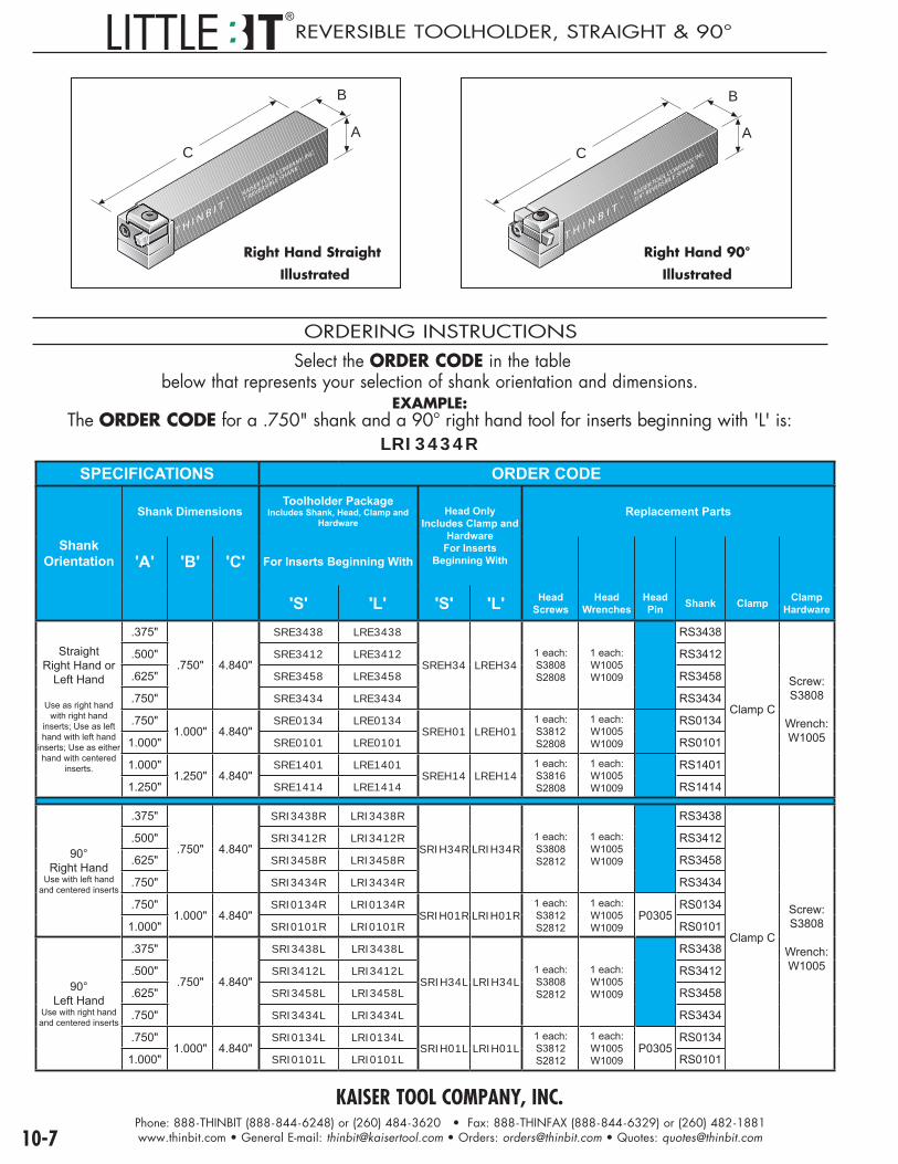
KAISER TOOL COMPANY, INC.Phone: 888-THINBIT (888-844-6248) or (260) 484-3620 • Fax: 888-THINFAX (888-844-6329) or (260) 482-1881www.thinbit.com • General E-mail: [email protected] • Orders: [email protected] • Quotes: [email protected]
®REVERSIBLE TOOLHOLDER, STRAIGHT & 90°
C
B
A
T H I N B I T®
KAISER TOOL COMPANY, INC.
1' REVERSIBLE SHANK
Right Hand Straight
Illustrated
C
B
A
T H I N B I T®
KAISER TOOL COMPANY, INC.
3/4" REVERSIBLE SHANK
Right Hand 90°
Illustrated
ORDERING INSTRUCTIONS
Select the ORDER CODE in the table below that represents your selection of shank orientation and dimensions.
EXAMPLE: The ORDER CODE for a .750" shank and a 90° right hand tool for inserts beginning with 'L' is:
LRI3434RSPECIFICATIONS ORDER CODE
ShankOrientation
Shank DimensionsToolholder Package
Includes Shank, Head, Clamp and Hardware
Head OnlyIncludes Clamp and
HardwareFor Inserts
Beginning With
Replacement Parts
'A' 'B' 'C' For Inserts Beginning With
'S' 'L' 'S' 'L' HeadScrews
HeadWrenches
HeadPin Shank Clamp Clamp
Hardware
StraightRight Hand or
Left Hand
Use as right hand with right hand
inserts; Use as left hand with left hand
inserts; Use as either hand with centered
inserts.
.375"
.750" 4.840"
SRE3438 LRE3438
SREH34 LREH341 each:S3808S2808
1 each:W1005W1009
RS3438
Clamp C
Screw:S3808
Wrench:W1005
.500" SRE3412 LRE3412 RS3412
.625" SRE3458 LRE3458 RS3458
.750" SRE3434 LRE3434 RS3434
.750"1.000" 4.840"
SRE0134 LRE0134SREH01 LREH01
1 each:S3812S2808
1 each:W1005W1009
RS0134
1.000" SRE0101 LRE0101 RS0101
1.000"1.250" 4.840"
SRE1401 LRE1401SREH14 LREH14
1 each:S3816S2808
1 each:W1005W1009
RS1401
1.250" SRE1414 LRE1414 RS1414
90°Right Hand
Use with left hand and centered inserts
.375"
.750" 4.840"
SRI3438R LRI3438R
SRIH34R LRIH34R1 each:S3808S2812
1 each:W1005W1009
RS3438
Clamp C
Screw:S3808
Wrench:W1005
.500" SRI3412R LRI3412R RS3412
.625" SRI3458R LRI3458R RS3458
.750" SRI3434R LRI3434R RS3434
.750"1.000" 4.840"
SRI0134R LRI0134RSRIH01R LRIH01R
1 each:S3812S2812
1 each:W1005W1009
P0305RS0134
1.000" SRI0101R LRI0101R RS0101
90°Left Hand
Use with right hand and centered inserts
.375"
.750" 4.840"
SRI3438L LRI3438L
SRIH34L LRIH34L1 each:S3808S2812
1 each:W1005W1009
RS3438
.500" SRI3412L LRI3412L RS3412
.625" SRI3458L LRI3458L RS3458
.750" SRI3434L LRI3434L RS3434
.750"1.000" 4.840"
SRI0134L LRI0134LSRIH01L LRIH01L
1 each:S3812S2812
1 each:W1005W1009
P0305RS0134
1.000" SRI0101L LRI0101L RS0101

KAISER TOOL COMPANY, INC.Phone: 888-THINBIT (888-844-6248) or (260) 484-3620 • Fax: 888-THINFAX (888-844-6329) or (260) 482-1881www.thinbit.com • General E-mail: [email protected] • Orders: [email protected] • Quotes: [email protected] 10-8
RO
UN
DTO
OLH
OLD
ERS
®ROUND INTERNAL & REVERSIBLE TOOLHOLDERS
Right Hand Illustrated1"
C
A ROUND INTERNAL ORDERING INSTRUCTIONS
Select the ORDER CODE in the table below that represents your selection of shank orientation and dimensions.
EXAMPLE: The ORDER CODE for a .625", 5.5" long round shank for
inserts beginning with 'L' is:LR5806
SPECIFICATIONS ORDER CODE
ShankOrientation
MinimumBore
Diameter
without pin
Shank DimensionsToolholder Package
Includes Shank, Clamp and Hardware
Replacement Parts
'A' 'C' For Inserts Beginning With
'S' 'L' Clamp Screw Wrench Pin
Right Hand or
Left Hand
Use as right hand with left hand inserts;
Use as left hand with right hand inserts; Use as either hand with centered inserts.
1.125"
.500"
5.500"
SR1206 - - -
Clamp C S3808 W1005 P0305
.625" SR5806 - - -
.750" SR3406 - - -
1.000"SR0106 - - -
11.875" SR0112 - - -
1.187"(1.250"
for insert beginning with
'LGT')
.500"
5.500"
- - - LR1206
.625" - - - LR5806
.750" - - - LR3406
1.000"- - - LR0106
11.875" - - - LR0112
�����
���
���
��� �� � �
�����
� ����
!����� ���
��� !�
���
��
�����
Right Hand Illustrated1"
5.5"
A ROUND REVERSIBLE ORDERING INSTRUCTIONS
SPECIFICATIONS ORDER CODE
ShankOrientation
Shank Dimensions
Toolholder PackageIncludes Shank, Head, Clamp and
HardwareReplacement Parts
'A' For Inserts Beginning WithHead Only
Includes Clamp and HardwareFor Inserts Beginning With
'S' 'L' 'S' 'L' HeadScrews
HeadWrenches Shank Clamp Clamp
Hardware
Right Hand orLeft Hand
Use as right hand with right hand inserts; Use as
left hand with left hand inserts; Use
as either hand with centered inserts.
.500" SROE12 LROE12
SROEH LROEH1 each:S5806S2810
1 each:W1006W1009
RROE12
Clamp C
Screw:S3808
Wrench:W1005
.625" SROE58 LROE58 RROE58
.750" SROE34 LROE34 RROE34
1.000" SROE01 LROE01 RROE01
Select the ORDER CODE in the table below thatrepresents your selection of shank dimensions.
EXAMPLE: The ORDER CODE for a .625" round shank for inserts
beginning with 'L' is:LROE58

KAISER TOOL COMPANY, INC.Phone: 888-THINBIT (888-844-6248) or (260) 484-3620 • Fax: 888-THINFAX (888-844-6329) or (260) 482-1881www.thinbit.com • General E-mail: [email protected] • Orders: [email protected] • Quotes: [email protected]
®45° TOOLHOLDERS
Note: If groove width is less than .080" it may require a special insert.
Right Hand Illustrated
45° ORDERING INSTRUCTIONS
Select the ORDER CODE in the table below thatrepresents your selection of shank orientation and dimensions.
EXAMPLE: The ORDER CODE for a .750" shank, right hand tool
for inserts beginning with 'L' is:L453434R
SPECIFICATIONS ORDER CODE
ShankOrientation
Shank DimensionsToolholder Package
Includes Shank, Clamp and Hardware
Replacement Parts
'A' 'B' 'C' For Inserts Beginning With
'S' 'L' Clamp Screw Wrench Pin
Right HandUse with left hand
and centered inserts for
counter-clockwise rotation
.375"
.750"4.840"
S453438R L453438R
Clamp Q
S3808 W1005 * C0509
.500" S453412R L453412R
.625" S453458R L453458R
.750" S453434R L453434R
1.000" 1.000" S450101R L450101R
Left HandUse with right
hand and centered inserts
for clockwise rotation
.375"
.750"4.840"
S453438L L453438L
Clamp R
.500" S453412L L453412L
.625" S453458L L453458L
.750" S453434L L453434L
1.000" 1.000" S450101L L450101L
* Roll Pin sizes may have changed due to manufacturing updates. Toolholders will be shipped with the correct item. Replacement pin (C0509) will contain two items (P0204 & P0305) to accomodate either revision.

For more informationabout our services,
please visitwww.kaiserlaserimages.com
24/7www.thinbit.com
E-MAIL: [email protected] ORDERS: [email protected] QUOTES: [email protected]
P L EL ● G
B C ● SS ● P I
SECTION 3CD, TD, TP AND TRIGON STYLE INDEXABLE BORING BARS

SWISS TOOLINGSOLUTIONS FOR
GROOVING • THREADING • PARTING • BORING • TURNING
FACE GROOVING • SPECIALS • FORM TOOLS
ASK FOR OUR SWISS FLYER OR GO TO WWW.THINBIT.COM/SWISS
WHAT CAN YOU DO WITH A SINGLE INSERT?

FACE GROOVING
PARTINGBORING
TURNING
THREADING TOOLHOLDERS
FORM TOOLS
GROOVING
FORM-A-GROOVE® tools consist of simple grooves or complex combinations of grooves,
arcs, angles, convex and concave radii, as well as special thread forms.PG
8-7PG8-7
PG8-1
THINBIT® is an industry leader at designing and manufacturing custom tooling.
e-mail your application to [email protected]
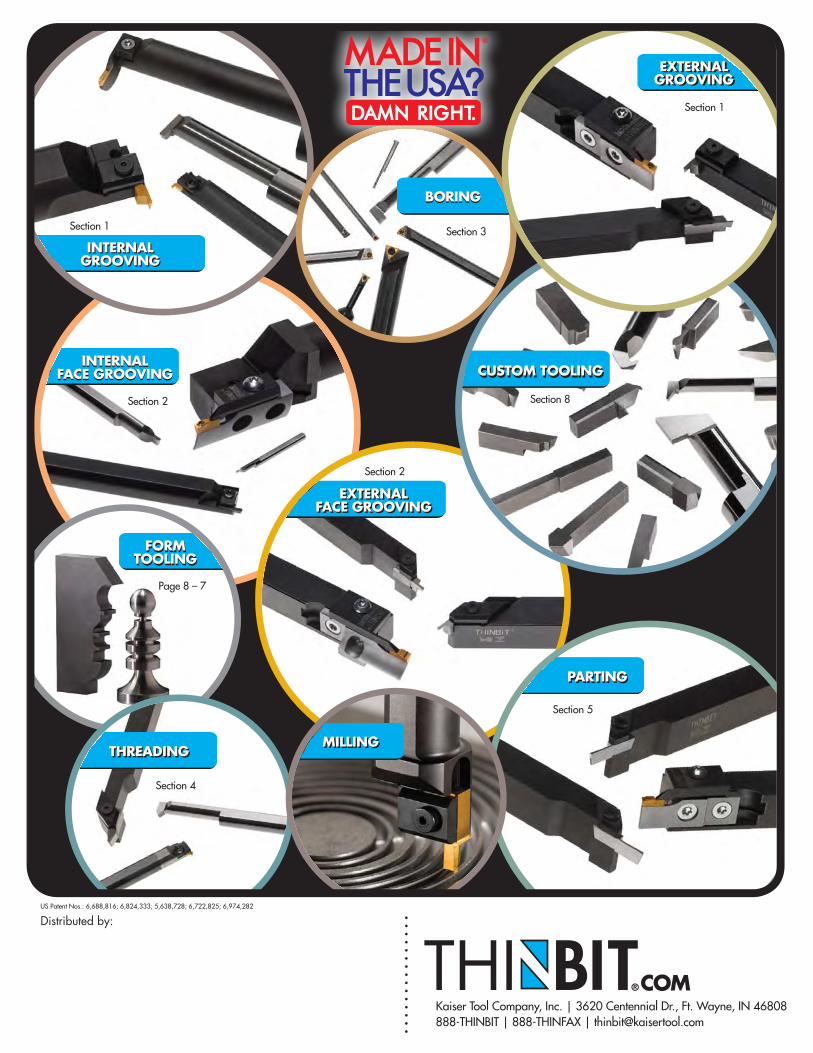
BORING
INTERNALFACE GROOVING
PARTING
EXTERNALFACE GROOVING
THREADING
Section 1 Section 3
Page 8 – 7
Section 2
Section 5
Section 4
®COM
Distributed by:
®
Kaiser Tool Company, Inc. | 3620 Centennial Dr., Ft. Wayne, IN 46808888-THINBIT | 888-THINFAX | [email protected]
US Patent Nos.: 6,688,816; 6,824,333; 5,638,728; 6,722,825; 6,974,282
FORM TOOLING
BORING
INTERNALFACE GROOVING
EXTERNALFACE GROOVING
THREADING
FORM TOOLING
EXTERNAL GROOVINGEXTERNAL
GROOVING
Section 8
Section 1
CUSTOM TOOLINGCUSTOM TOOLING
INTERNALGROOVINGINTERNAL
GROOVING
MILLINGMILLING
PARTING
Section 2

2018 THINBIT® Catalog Index
Introduction – Information and General Information Pg. 5 General Information: Hours; Shipments; Terms; Pricing; Returns; Credit
Pg. 6 Standard Product Index sorted by Product Code (Laser Marked Codes on most Tools) Pg. 7 Discontinued Standard Product Index Section 1 – Grooving (Inserts and Solid Carbide Tools) Pg. 1‐1 Product Selection Guide for External and Internal Grooving Tools (Pictures and Descriptions) Pg. 1‐2 Orientation guide for External and Internal Grooving Tools Pg. 1‐3 Tools for Internal Diameters of .125” and Larger (MICROBIT® Solid Carbide Tooling) Pg. 1‐4 Order Instructions for MICROBIT® Solid Carbide Tooling Pg. 1‐5 Tools for Internal Diameters of .325” and Larger (MINI‐GROOVE ‘N TURN®) Pg. 1‐6 Ordering Instructions for MINI‐GROOVE ‘N TURN® I.D. Grooving Tools Pg. 1‐7 Tools for Internal Diameters of 1.000” and Larger (DEEPGROOVE®) Pg. 1‐8 Ordering Instructions for DEEPGROOVE® I.D. Grooving Tools Pg. 1‐9 External and Internal Grooving Tools of 1.250” and Larger (GROOVE ‘N TURN®) Pg. 1‐10 Ordering Instructions for GROOVE ‘N TURN® O.D & I.D. Grooving Tools Pg. 1‐11 External and Internal Grooving Tools of 1.250” and Larger for Static O‐Rings (GROOVE ‘N TURN®) Pg. 1‐12 Ordering Instructions for GROOVE ‘N TURN® Static O‐Ring Inserts Pg. 1‐13 External Grooving/Parting Packages (Inserts are on Pg. 6‐1) with Depth of Cut up to 1” (DEEPGROOVE®) Pg. 1‐14 Ordering Instructions for DEEPGROOVE® O.D. Grooving and Parting Tools Section 2 – Face Grooving (Inserts and Solid Carbide Tools) Pg. 2‐1 Product Selection Guide for Face Grooving Tools (Pictures and Descriptions) Pg. 2‐2 Orientation Guide for External and Internal Face Grooving Tools Pg. 2‐3 Internal Diameters of .125” and Larger (MICROBIT® Solid Carbide Tools) Pg. 2‐4 Ordering Instructions for MICROBIT® Face Grooving Solid Carbide Tools Pg. 2‐5 Internal Diameters of .415” and Larger (MINI‐GROOVE ‘N TURN®) Pg. 2‐6 Ordering Instructions for MINI‐GROOVE ‘N TURN® Face Grooving Solid Carbide Tools Pg. 2‐7 Internal Diameters of 1.574” and larger (DEEPGROOVE®) Pg. 2‐8 Ordering Instructions for DEEPGROOVE® I.D. Face Grooving Tools Pg. 2‐9 Face Grooving Inserts for .300”, .750”, 1.250” and 3” Major Diameters (GROOVE ‘N TURN®) Pg. 2‐10 Ordering Instructions for GROOVE ‘N TURN® Face Grooving Tools Pg. 2‐11 Dovetail O‐Rings .300”, .750”, 1.250”, 3” (Groove ‘N Turn®) Pg. 2‐12 Ordering Instructions for GROOVE ‘N TURN® Dovetail O‐Ring Face Grooving Inserts Pg. 2‐13 Static O‐Rings with Groove Widths .086”, .103”, .122”, 125”, .138” (GROOVE ‘N Turn®) Pg. 2‐14 Ordering Instructions for GROOVE ‘N TURN® Static O‐Ring Face Grooving Inserts Pg. 2‐15 External Face Grooving Packages (Inserts are on Pg 6‐1) with Depth of Cut up to 1” (DEEPGROOVE®) Pg. 2‐16 Ordering Instructions for DEEPGROOVE® Face Grooving Tools Section 3 – Boring, Profiling & Turning Tools (Inserts, Bars and Shanks) Pg. 3‐1 Product selection guide for Boring, Profiling & Turning Tools (Pictures and Descriptions) Pg. 3‐2 Orientation Guide for Boring, Profiling & Turning
Pg. 3‐3 Boring Diameters .073” and larger (MICROBIT® Solid Carbide Tools) Pg. 3‐4 Ordering Instructions for MICROBIT® Boring Tools
Pg. 3‐5 Profiling & Reverse Profiling Diameters .125” and larger (MICROBIT® Solid Carbide Tools) Pg. 3‐7 Boring Diameters .210” and larger (MINI‐BORE® Trigon®) (MBE Series) Pg. 3‐9 Boring Diameters .330” and larger (MINI‐BORE ® Trigon®) (MBF Series) Pg. 3‐10 Boring Diameters .410” and larger (MINI‐BORE ® Trigon®) (MBG Series) Pg. 3‐11 Boring Diameters .165” and larger (MINI‐BORE ®) (MBZ Series) Pg. 3‐12 Ordering Instructions for MINI‐BORE® CD style MBZ Series Boring Bars and Inserts
Pg. 3‐13 Boring Diameters .180” and larger (MINI‐BORE ®) (MBA Series boring bars) Pg. 3‐14 Boring Diameters .180” and larger (MINI‐BORE ®) (MBA Series boring inserts) Pg. 3‐15 Boring Diameters .300” and larger (MINI‐BORE ®) (MBB Series boring bars) Pg. 3‐16 Boring Diameters .300” and larger (MINI‐BORE ®) (MBB Series boring inserts) Pg. 3‐17 Boring Diameters .430” and larger (MINI‐BORE®) (MBC Series boring bars) Pg. 3‐18 Boring Diameters .430” and larger (MINI‐BORE®) (MBC Series boring inserts) Section 4 – Threading and Chamfering (Inserts and Solid Carbide Tools) Pg. 4‐1 Product Selection Guide for Threading and Chamfering Tools (Pictures and Descriptions)
Pg. 4‐2 Orientation Guide for Threading and Chamfering Tools Pg. 4‐3 Internal Threading for Diameters .077” and Larger (MICROBIT® Solid Carbide Tools) Pg. 4‐4 Ordering Instructions for I.D. Threading Tools
Pg. 4‐5 Internal ACME Threading for Diameters .187” and Larger (MICROBIT® Solid Carbide Tools) Pg. 4‐6 Ordering Instructions for MICROBIT® I.D. ACME Threading Tools
Pg. 4‐7 Internal Threading for Diameters .325” and Larger (Mini‐Groove ‘N Turn®) Pg. 4‐8 Ordering Instructions for MINI GROOVE ‘N TURN® I.D. Threading Tools
Pg. 4‐9 External Threading within .065” of a Shoulder (Groove ‘N Turn®) Pg. 4‐10 Ordering Instructions for GROOVE ‘N TURN® Threading Inserts

Pg. 4‐11 External Threading and Internal ACME Threading with 1.250” Minimum Bore (Groove ‘N Turn®) Pg. 4‐12 Ordering Instructions for GROOVE ‘N TURN® ACME Threading Inserts
Pg. 4‐13 External and Internal Chamfering for Internal Diameters of 1.250” and Larger (Groove ‘N Turn®) Pg. 4‐14 Ordering Instructions for GROOVE ‘N TURN® Chamfering Inserts
Section 5 – Parting (Inserts) Pg. 5‐1 Pictures and Descriptions of Parting Tools
Pg. 5‐2 Orientation Guide for Parting Tools Pg. 5‐3 Parting Inserts up to 1” Diameter (GROOVE ‘N TURN®) Pg. 5‐4 Ordering Instructions for GROOVE ‘N TURN® Parting Inserts
Section 6 – DEEPGROOVE® OD and ID Face Grooving Inserts Pg. 6‐1 2,3,4,5 and 6MM Inserts for Face Grooving (DEEPGROOVE®)
Pg. 6‐2 Ordering Instructions for DEEPGROVE® Face Grooving Inserts Section 7 – Toolholders (additional DEEPGROOVE® Toolholders on pg. 1‐8, 1‐14,2‐8, 2‐16) Pg. 7‐1 Product Selection Guide for Toolholders Pg. 7‐2 Round and Square Adapters Pg. 7‐3 Straight GROOVE ‘N TURN® Toolholders Pg. 7‐4 90° GROOVE ‘N TURN® Toolholders Pg. 7‐5 Swiss Screw Machine GROOVE ‘N TURN® Toolholders Pg. 7‐6 Swiss Screw Machine GROOVE ‘N TURN® Face Grooving Toolholders Pg. 7‐7 Round Reversible GROOVE ‘N TURN® Toolholders Pg. 7‐8 Round Internal GROOVE ‘N TURN® Toolholders Pg. 7‐9 Multi‐Insert Square FORM‐A‐GROOVE® Toolholders Pg. 7‐10 Multi‐Insert Round FORM‐A‐GROOVE® Toolholders Pg. 7‐11 45° and 30°/60° GROOVE ‘N TURN® Toolholders
Pg. 7‐12 Ordering Instructions for GROOVE ‘N TURN® 45° and 30°/60° Toolholders Pg. 7‐13 Round DEEPGROOVE® Shanks with External Heads Pg. 7‐14 Square DEEPGROOVE® Shanks with Internal Face Grooving Heads
Section 8 – Custom Inserts and Tools Pg. 8‐1 Custom DESIGN‐A‐GROOVE® Insert Instructions and Ordering Process Pg. 8‐2 Custom Face Grooving Tooling Specifications Pg. 8‐3 Definition of Insert Modifications Pg. 8‐4 Insert Modification Specification Sheet Pg. 8‐5 Custom Threading Tooling Specifications Pg. 8‐6 Solid Carbide MICROBIT® Custom Blanks Pg. 8‐7 Custom FORM‐A‐GROOVE® Multi Groove Tools Section 9 – Technical Information Pg. 9‐1 General Information Pg. 9‐2 Page Omitted Pg. 9‐3 External Application Reference Pg. 9‐4 Internal application Reference Pg. 9‐5 Insert Grade Information Pg. 9‐6 Insert Coating Information Pg. 9‐7 Troubleshooting Information Pg. 9‐8 General Toolholder Information Pg. 9‐9 Grooving ‐ Geometry and Set‐Up Information Pg. 9‐10 Grooving ‐ Speeds and Feeds Pg. 9‐11 Face Grooving ‐ Geometry and Set‐Up Information Pg. 9‐12 Face Grooving ‐ Speeds and Feeds Pg. 9‐13 Boring & Turning – Geometry and Set‐Up Information Pg. 9‐14 Boring & Turning – Speeds and Feeds for MBE, MBF and MBG Boring Bars Pg. 9‐15 Boring & Turning – Speeds and Feeds for MBZ, MBA, MBB and MBC Boring Bars Pg. 9‐16 Boring & Turning – Speeds and Feeds for MBA, MBB and MBC PCD and CBN Tipped Inserts Pg. 9‐17 Threading – Geometry and Set‐Up Information Pg. 9‐18 Threading – Speeds and Feeds Pg. 9‐19 Parting – Geometry and Set‐Up Information Pg. 9‐20 Parting – Speeds and Feeds Section 10 ‐ LITTLEBIT® Inserts and Toolholders Pg. 10‐1 O.D./I.D. Grooving Inserts Pg. 10‐2 Parting Inserts Pg. 10‐3 O.D./I.D. Threading Inserts Pg. 10‐4 Ground Blanks and Grooving Insert Sets Pg. 10‐5 Flushtop & Hardinge Toolholders Pg. 10‐6 Swiss Screw Machine and Swiss Face Toolholders Pg. 10‐7 Reversible Toolholders, Straight and 90°