88000 SERIES/MICROTEK BR N - c.searspartsdirect.com · Uso con et kit aprobado del la conexion de...
8
88000 SERIES/MICROTEK ®SYSTEM IV CONVERTIBLE RANGE HOOD INSTALLATION INSTRUCTIONS BR N SERIE 88000/MICROTEK ®SISTEMA IV INSTRUCClONES PARA INSTALAClON DE CAPUCHA PARA ESTUFA ELECTRICA CONVERTIBLE ;_"t ,]'1'_; i"_ I'_ I _"_'Tlq Follow all general steps and: purchase a 97007662 Microtek ® System IV Filter Kit, available from your Broan Distributor or write Broan Mfg. Co., Inc., P.O. Box 140, Hartford WI, 53027, USA. i[]1_- J_ Siga todos los pasos generales y: compre un juego de filtro 97007662 Microtek ®Sistema IV, disponible por parte de su distribuidor Broan o escriba a Broan Mfg. Co., Inc., P.O. Box 140, Hartford Wl 53207, USA. INTENDEDFOR DOMESTIC COOKINGONLY. WARNING TO REDUCE THE RISK OF FIRE, ELECTRIC SHOCK, OR INJURY TO PERSONS, OBSERVE THE FOLLOWING: 1. Use this unit only in the manner intended by the manufacturer. If you have questions, contact the manufacturer at the address or telephone number listed in the warranty. 2. Before servicing or cleaning unit, switch power off at service panel and lock the service disconnecting means to prevent power from being switched on accidentally. When the service disconnecting means cannot be locked, securely fasten a prominent warn- ing device, such as a tag, to the service panel. 3. Installation work and electrical wiring must be done by a qualified person(s) in accordance with all appli- cable codes and standards, including fire-rated con- struction codes and standards. 4. Sufficient air is needed for proper combustion and exhausting of gases through the flue (chimney) of fuel burning equipment to prevent backdrafting. Fol- low the heating equipment manufacturer's guideline and safety standards such as those published by the National Fire Protection Association (NFPA), and the American Society for Heating, Refrigeration and Air Conditioning Engineers (ASHRAE), and the local code authorities. 5. When cutting or drilling into wall or ceiling, do not damage electrical wiring and other hidden utilities. 6. To reduce the risk of fire or electric shock, do not use this range hood with an additional speed control device. 7. Ducted fans must always be vented to the outdoors. 8. To reduce the risk of fire, use only metal ductwork. 9. Use with approved cord-connection kit only. 10. This unit must be grounded. TO REDUCE THE RISK OF A RANGE TOP GREASE FIRE: 1. Never leave surface units unattended at high set- tings. Boilovers cause smoking and greasy spitlovers that may ignite. Heat oils slowly on tow or medium settings. 2. Always turn hood ON when cooking at high heat or when cooking flaming foods. 3. Clean ventilating fans frequently. Grease should not be allowed to accumulate on fan or filter. 4. Use proper pan size. Always use cookware appro- priate for the size of the surface element. TO REDUCE THE RISK OF INJURY TO PERSONS IN THE EVENT OF A RANGE TOP GREASE FIRE, OBSERVE THE FOLLOWING:* 1. SMOTHER FLAMES with a close-fitting lid, cookie sheet, or metal tray, then turn off the burner. BE CAREFUL TO PREVENT BURNS. If the flames do not go out immediately, EVACUATE AND CALL THE FIRE DEPARTMENT. 2. NEVER PICK UP A FLAMING PAN -- You may be burned. 3. DO NOT USE WATER, including wet dishcloths or towels - violent steam explosion will result. 4. Use an extinguisher ONLY if: A. You know you have a Class ABC extinguisher and you already know how to operate it. B. The fire is small and contained in the area where it started. C. The fire department is being called. D. You can fight the fire with your back to an exit. * Based on "Kitchen Fire Safety Tips" published by NFPA. INSTALLER: Leave This Manual With The Homeowner. INSTALADOR: Dejeestemanualconelduehodecasa. DUENODECASA:Informaciondel PREVISTOPARA COCINAR DOMI STICO SOLAMENTE. ADVERTENCIA A PARA REDUCIR EL RIESGO DE INCENDIO, DESCARGA ELECTRICA, O LESIONES PERSONALES, CUMPLA CON LOS SIGUlENTES PUNTOS: 1. Solamente use esta unidad de Ia manera propuesta por el fabricante. Si tiene alguna pregunta, pengase en contacto con el fabricante en la direcci6n o tetefono anotados en la garantfa. 2. Antes de limpiar o de porter en servicio la unidad, apague el interruptor en et panel de servicio, y asegure el panel de servicio para evitar que se encienda accidentalmente. Cuando el dispositivo para desconectar et servicio etectrico no puede ser cerrado con algun tipo de traba, sujete fuertemente al panel de servicio, una etiqueta de advertencia prominente. 3. El trabajo de instalaci6n y el cableado etectrico deben Ilevarse a cabo por personal catificado de acuerdo con todos los cedigos y las normas apticabtes, inctuyendo los cedigos y normas de construcci6n contra incendios. 4. Se requiere una cantidad de aire suficiente para ta combustien y escape de gases por ta chimenea det equipo que quema combustible para evitar la retrogresien de ta llama. Siga las especificaciones y estandares de seguridad det fabricante, tales como los que pubtica ta Asociacien Nacional de Proteccion Contra Incendios (NFPA pot sus sigIes en ingles), y la Sociedad Americana de Ingenieros de Calefacci6n, Refrigeraci6n y Aire Acondicionado (ASHRAE), y los c6digos de las autoridades locales. 5. Cuando corte o tatadre en una pared o cielo raso, no da_e cabteado etectrico u otras instataciones no visibles. 6. Para reducir el riesgo de incendio o de descarga electrica, no utilice este ventiIador con ningt_n dispositivo de una control de vetocidad de estado selido adicional. 7. Los abanicos con ducto debera.n siempre tener una satida hacia et exterior. 8. Para reducir et riesgo de incendio, use s6to ductos de metal. 9. Uso con et kit aprobado del la conexion de la cuerda sotamente. 10. Esta unidad se debe instatar con tierra efectiva. PARA REDUCIR EL RIESGO DE INCENDIO DEBIDO A GRASA ACUMULADA EN LAS HORNILLAS: 1. Nunca deje sin atender las unidades de superficie cuando tengan ajustes altos. Los reboses pueden provocar humo y derrames grasosos que se pueden incendiar. CaNente lentamente el aceite en un ajuste bajo o medio. 2. Siempre ENCIENDA ta campana cuando cocine con aIta temperatura o cuando cocine alimentos que se puedan incendiar. 3. Limpie con frecuencia los ventiladores. No debe permitir que la grasa se acumule en el ventitador ni en el fittro. 4. Utitice un sarten de tama_o adecuado. Siempre utitice el utensilio adecuado al tama_o del elemento de superficie. PARA REDUCIR EL RIESGO DE LESIONES PERSONALES EN CASO DE INCENDIO DE GRASA EN LA SUPERFICIE DE LA ESTUFA, OBSERVAR LO SIGUIENTE:* 1. Cubra y sofoque las llamas con una tapa ajustada, azafate de hornear gattetas, o un azafate de metal, y luego apague et catentador. TENGA CUIDADO PARA EVITAR QUEMADURAS. Si las llamas no se apagan inmediatamente, HAY QUE EVACUAR Y LLAMAR LOS BOMBEROS. 2. NUNCA ALCE UNA SARTEN QUE TENGA LLAMAS - Usted se puede quemar. 3. NO USE AGUA, inctuyendo trapos lavaptatos mojados o toaltas - puede que ocurran exptosiones de vapor viotentas. 4. Use un extintor SOLAMENTE si: A. usted sabe que tiene un extintor ABC y ya sabe usarto. B. el fuego es peque_o y esta. restringido al a.rea donde empez6. HOMEOWNER: Use and Care Information on Page 5. uso y mantenimiento en la pagina6.
Transcript of 88000 SERIES/MICROTEK BR N - c.searspartsdirect.com · Uso con et kit aprobado del la conexion de...

88000 SERIES/MICROTEK®SYSTEMIVCONVERTIBLE RANGE HOODINSTALLATION INSTRUCTIONS BR N
SERIE 88000/MICROTEK ®SISTEMA IVINSTRUCClONES PARA INSTALAClONDE CAPUCHA PARA ESTUFAELECTRICA CONVERTIBLE
;_"t ,]'1'_; i"_ I'_ I_"_'Tlq
Follow all general steps and:
purchase a 97007662 Microtek ® System IV FilterKit, available from your Broan Distributor or writeBroan Mfg. Co., Inc., P.O. Box 140, Hartford WI,53027, USA.
i[]1_- J_ Siga todos los pasos generales y:
compre un juego de filtro 97007662 Microtek ®SistemaIV, disponible por parte de su distribuidor Broan oescriba a Broan Mfg. Co., Inc., P.O. Box 140, HartfordWl 53207, USA.
INTENDEDFORDOMESTIC
COOKINGONLY.
WARNINGTO REDUCE THE RISK OF FIRE, ELECTRIC SHOCK, ORINJURY TO PERSONS, OBSERVE THE FOLLOWING:
1. Use this unit only in the manner intended by themanufacturer. If you have questions, contact themanufacturer at the address or telephone numberlisted in the warranty.
2. Before servicing or cleaning unit, switch power offat service panel and lock the service disconnectingmeans to prevent power from being switched onaccidentally. When the service disconnecting meanscannot be locked, securely fasten a prominent warn-ing device, such as a tag, to the service panel.
3. Installation work and electrical wiring must be doneby a qualified person(s) in accordance with all appli-cable codes and standards, including fire-rated con-struction codes and standards.
4. Sufficient air is needed for proper combustion andexhausting of gases through the flue (chimney) offuel burning equipment to prevent backdrafting. Fol-low the heating equipment manufacturer's guidelineand safety standards such as those published bythe National Fire Protection Association (NFPA), andthe American Society for Heating, Refrigeration andAir Conditioning Engineers (ASHRAE), and the localcode authorities.
5. When cutting or drilling into wall or ceiling, do notdamage electrical wiring and other hidden utilities.
6. To reduce the risk of fire or electric shock, do notuse this range hood with an additional speed controldevice.
7. Ducted fans must always be vented to the outdoors.8. To reduce the risk of fire, use only metal ductwork.9. Use with approved cord-connection kit only.10. This unit must be grounded.TO REDUCE THE RISK OF A RANGE TOP GREASE
FIRE:1. Never leave surface units unattended at high set-
tings. Boilovers cause smoking and greasy spitloversthat may ignite. Heat oils slowly on tow or mediumsettings.
2. Always turn hood ON when cooking at high heat orwhen cooking flaming foods.
3. Clean ventilating fans frequently. Grease should notbe allowed to accumulate on fan or filter.
4. Use proper pan size. Always use cookware appro-priate for the size of the surface element.
TO REDUCE THE RISK OF INJURY TO PERSONS INTHE EVENT OF A RANGE TOP GREASE FIRE, OBSERVETHE FOLLOWING:*
1. SMOTHER FLAMES with a close-fitting lid, cookiesheet, or metal tray, then turn off the burner. BECAREFUL TO PREVENT BURNS. If the flames donot go out immediately, EVACUATE AND CALL THEFIRE DEPARTMENT.
2. NEVER PICK UP A FLAMING PAN -- You may beburned.
3. DO NOT USE WATER, including wet dishcloths ortowels - violent steam explosion will result.
4. Use an extinguisher ONLY if:A. You know you have a Class ABC extinguisher
and you already know how to operate it.B. The fire is small and contained in the area where
it started.C. The fire department is being called.D. You can fight the fire with your back to an exit.* Based on "Kitchen Fire Safety Tips" published byNFPA.
INSTALLER: Leave This Manual With The Homeowner.INSTALADOR:Dejeestemanualconel duehodecasa. DUENODECASA:Informaciondel
PREVISTOPARACOCINAR
DOMI STICOSOLAMENTE.
ADVERTENCIA APARA REDUCIR EL RIESGO DE INCENDIO, DESCARGAELECTRICA, O LESIONES PERSONALES, CUMPLA CON LOSSIGUlENTES PUNTOS:
1. Solamente use esta unidad de Ia manera propuesta por elfabricante. Si tiene alguna pregunta, pengase en contactocon el fabricante en la direcci6n o tetefono anotados en la
garantfa.2. Antes de limpiar o de porter en servicio la unidad, apague el
interruptor en et panel de servicio, y asegure el panel deservicio para evitar que se encienda accidentalmente.Cuando el dispositivo para desconectar et servicio etectricono puede ser cerrado con algun tipo de traba, sujetefuertemente al panel de servicio, una etiqueta de advertenciaprominente.
3. El trabajo de instalaci6n y el cableado etectrico debenIlevarse a cabo por personal catificado de acuerdo contodos los cedigos y las normas apticabtes, inctuyendo loscedigos y normas de construcci6n contra incendios.
4. Se requiere una cantidad de aire suficiente para tacombustien y escape de gases por ta chimenea det equipoque quema combustible para evitar la retrogresien de tallama. Siga las especificaciones y estandares de seguridaddet fabricante, tales como los que pubtica ta AsociacienNacional de Proteccion Contra Incendios (NFPA pot sussigIes en ingles), y la Sociedad Americana de Ingenieros deCalefacci6n, Refrigeraci6n y Aire Acondicionado (ASHRAE),y los c6digos de las autoridades locales.
5. Cuando corte o tatadre en una pared o cielo raso, no da_ecabteado etectrico u otras instataciones no visibles.
6. Para reducir el riesgo de incendio o de descarga electrica,no utilice este ventiIador con ningt_n dispositivo de unacontrol de vetocidad de estado selido adicional.
7. Los abanicos con ducto debera.n siempre tener una satidahacia et exterior.
8. Para reducir et riesgo de incendio, use s6to ductos demetal.
9. Uso con et kit aprobado del la conexion de la cuerdasotamente.
10. Esta unidad se debe instatar con tierra efectiva.PARA REDUCIR EL RIESGO DE INCENDIO DEBIDO A GRASAACUMULADA EN LAS HORNILLAS:
1. Nunca deje sin atender las unidades de superficie cuandotengan ajustes altos. Los reboses pueden provocar humo yderrames grasosos que se pueden incendiar. CaNentelentamente el aceite en un ajuste bajo o medio.
2. Siempre ENCIENDA ta campana cuando cocine con aItatemperatura o cuando cocine alimentos que se puedanincendiar.
3. Limpie con frecuencia los ventiladores. No debe permitirque la grasa se acumule en el ventitador ni en el fittro.
4. Utitice un sarten de tama_o adecuado. Siempre utitice elutensilio adecuado al tama_o del elemento de superficie.
PARA REDUCIR EL RIESGO DE LESIONES PERSONALES ENCASO DE INCENDIO DE GRASA EN LA SUPERFICIE DE LAESTUFA, OBSERVAR LO SIGUIENTE:*
1. Cubra y sofoque las llamas con una tapa ajustada, azafatede hornear gattetas, o un azafate de metal, y luego apagueet catentador. TENGA CUIDADO PARA EVITARQUEMADURAS. Si las llamas no se apagan inmediatamente,HAY QUE EVACUAR Y LLAMAR LOS BOMBEROS.
2. NUNCA ALCE UNA SARTEN QUE TENGA LLAMAS - Ustedse puede quemar.
3. NO USE AGUA, inctuyendo trapos lavaptatos mojados otoaltas - puede que ocurran exptosiones de vapor viotentas.
4. Use un extintor SOLAMENTE si:A. usted sabe que tiene un extintor ABC y ya sabe usarto.B. el fuego es peque_o y esta. restringido al a.rea donde
empez6.
HOMEOWNER: Use and Care Information on Page 5.usoy mantenimientoen la pagina6.
CAUTION ,A
1. For general ventilating use only. Do not use toexhaust hazardous or explosive materials andvapors.
2. To avoid motor bearing damage and noisy and/orunbalanced impellers, keep drywall spray,construction dust, etc. off power unit.
3. This product is equipped with a thermostat whichmay start fan automatically. To reduce the risk ofinjury, switch power off at service panel and lockservice panel to prevent power from being switchedon automatically.
4. Your hood motor has a thermal overload which wiltautomatically shut off the motor if it becomesoverheated. The motor will restart when it coolsdown. If the motor continues to shut off and restart,have the hood serviced.
5. For best capture of cooking impurities, your rangehood should be mounted 18-24" above the cookingsurface.
6. Please read specification label on product for furtherinformation and requirements.
TOOLS ANDMATERIALS REQUIREDTOOLS
[] Drill, electric or ratchet drive
[] 1-1/4" Spade bit
[] Common head and phillips head screwdriver[] Pliers
[] Tape measure or ruler and pencil
MATERIALS
[] Electrical wiring and supplies of type to complywith local codes
,]lllllllIlil:_i_IIk"lllilil_.[']Ti _Zi
[] Roof or wall cap
[] Roof cement or caulk
[] Duct and duct tape
[] One two-pack 97007662 Microtek ®System IVFilter Kit
For Installation On Kitchen Cabinets With RecessedBottoms Only:
[] Two 1" x 2" x 12" (approximate length) wood strips(purchase locally)
[] Four 1-1/4" long flat head wood screws (purchaselocally) to fasten strips to cabinet bottom
I_.-,fll b'I_P4_I_ i
I.,,"ll"_l 1,; 11 i [ 1.111 ( ill i
PLAN DUCTWORKINSTALLATION
.]lllllllIlil:_i_II_"IIIiIiI_.[o_il _,_
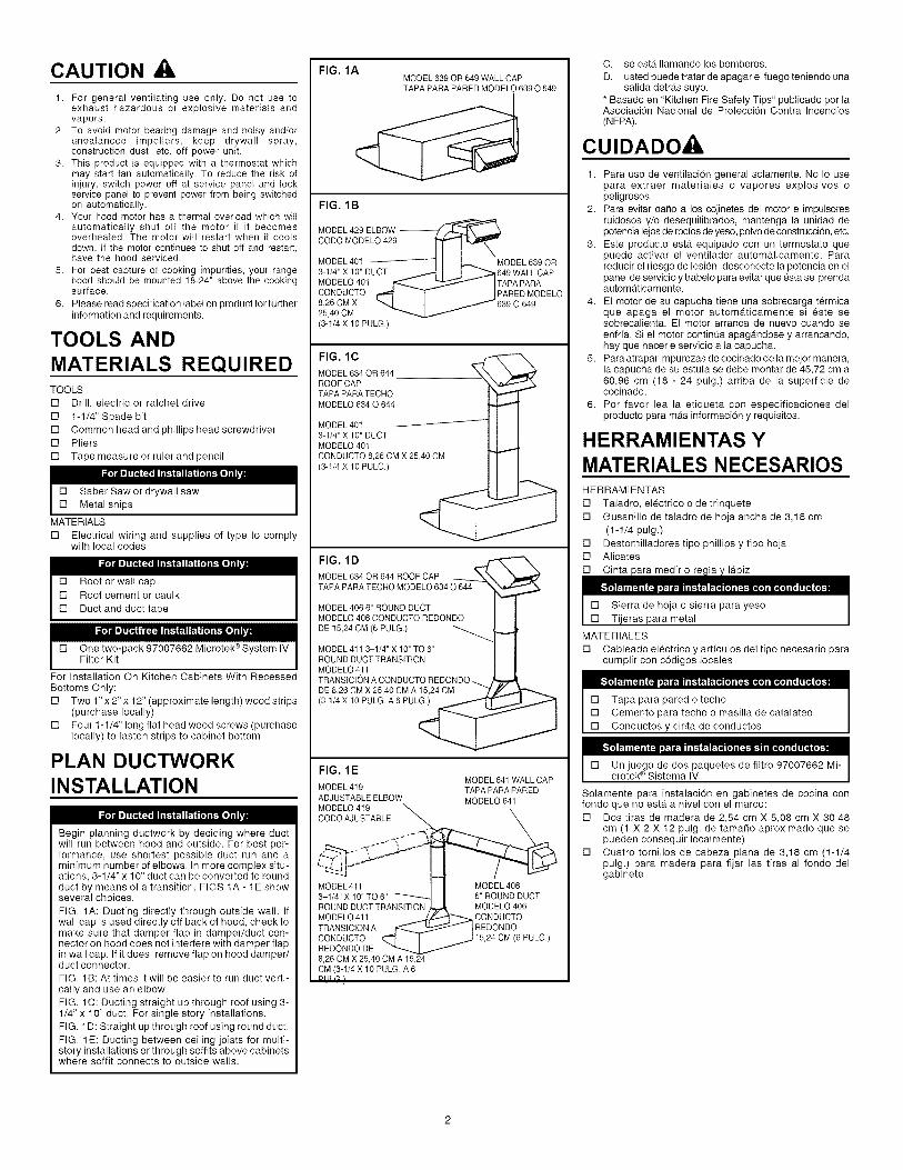
Begin planning ductwork by deciding where ductwill run between hood and outside. For best per-formance, use shortest possible duct run and aminimum number of elbows. In more complex situ-ations, 3-1/4" x 10" duct can be converted to roundduct by means of a transition. FIGS 1A - 1E showseveral choices.
FIG. 1A: Ducting directly through outside wall. Ifwall cap is used directly off back of hood, check tomake sure that damper flap in damper/duct con-nector on hood does not interfere with damper flapin wall cap. If it does, remove flap on hood damper/duct connector.
FIG. 1B: At times it will be easier to run duct verti-cally and use an elbow.
FIG. 1C: Ducting straight up through roof using 3-1/4" x 10" duct. For single story installations.FIG. 1D: Straight up through roof using round duct.
FIG. 1E: Ducting between ceiling joists for multi-story installations or through soffits above cabinetswhere soffit connects to outside walls.
FIG. 1AMODEL639 OR 649WALLCAPTAPAPARAPAREDMODELO639O 849
FIG. 1 B
MODEL 429 ELBOW --CODO MODELO 429
MODEL 40t MODEL 839 OR3-t/4" X 10" DUCT 649 WALL CAPMODELO 401 TAPA PARACONDUCTO PARED MODELO8,26 CM X 639 O 64925,40 CM
(3-1/4 X 10 PULG.)
FIG. lC
MODEL634 OR 844ROOFCAPTAPAPARATECHOMODELO834 O 644
MODEL 40t3-t/4" X 10" DUCTMODELO 401
CONDUCTO 8,28 CM X 25,40 CM(3-1/4 X 10 PULG.)
FIG. 1 D
MODEL634 OR 644 ROOFCAP
TAPAPARATECHOMODELO6340 644
MODEL406 6" ROUNDDUCT 1 IMODELO406 CONDUCTOREDONDO 1 I
DE 15,24CM (6PULG.) _ _,,._
MODEL411 3-1/4" X 10"TO 6" I iROUNDDUCTTRANSITION I IMODELO411 I ITRANSICIONA CONDUCTOREDONDO_DE8,26 CMX 25,40 CMA 15,24 CM _/_-/_(3-1/4X 10 PULG.A 6PULG.) _ ji ...-.-.-_
FIG. 1 EMODEL641WALLCAP
MODEL419 TAPAPARAPAREDADJUSTABLEELBOW MODELO641MODELO419CODOAJUSTABLE
.<_-"
MODEL4113-1/4" X 10" TO6"ROUNDDUCTTRANSITIONMODELO411TRANSIClONACONDUCTOREDONDODE8,26 CMX 25,40CM A 15,24CM(3-1/4X 10 PULG.A 6PI II G )
MODEL 4066" ROUND DUCTMODELO 406CONDUCTOREDONDO
(6 PULG.)
C. se esta Ilamando los bomberos.
D. usted puede tratar de apagar el fuego teniendo unasalida detras suyo.
* Basado en "Kitchen Fire Safety Tips" publicado por laAsociacion Nacional de ProtecciTn Contra Incendios(NFPA).
CUIDADO, ,
1. Para uso de ventilaci0n general solamente. No Io usepara extraer materiales o vapores explosivos opeligrosos.
2. Para evitar da_o a los cojinetes del motor e impulsoresruidosos y/o desequilibrados, mantenga la unidad depotencia lejos de rocfos de yeso, polvo de construcci0n, etc.
3. Este producto esta. equipado con un termostato quepuede activar el ventilador automa.ticamente. Parareducir el riesgo de lesi6n, desconecte la potencia en elpanel de servicio y trabelo para evitar que esta se prendaautomaticamente.
4. El motor de su capucha tiene una sobrecarga termicaque apaga el motor automa.ticamente si este sesobrecalienta. El motor arranca de nuevo cuando seenfffa. Si el motor continua apaga.ndose y arrancando,hay que hacerle servicio a la capucha.
5. Para atrapar impurezas de cocinado de la mejor manera,la capucha de su estufa se debe montar de 45,72 cm a60,96 cm (18 - 24 pulg.) arriba de la superficie decocinado.
6. Por favor lea la etiqueta con especificaciones delproducto para mas informacion y requisitos.
HERRAMIENTAS YMATERIALES NECESARIOSHERRAMIENTAS
[] Taladro, electrico o de trinquete
[] Gusanillo de taladro de hoja ancha de 3,18 cm
(1-1/4 pulg.)
[] Destornilladores tipo phillips y tipo hoja[] Alicates
[] Cinta para medir o regla y lapiz
i"'ll_ 1":111 [ _111 ( _111 tl. I itl. I I I I,.1 i_'l 1":ll4 [I] I [ _I,.1[1(I] I I I,lll] I [ I i'rr_li[l_!
[] Sierra de hoja o sierra para yeso[] Tijeras para meta
MATERIALES
[] Cableado electrico y artfculos del tipo necesario paracumplir con cTdigos locales
[] Tapa para pared o techo
[] Cemento para techo o masilla de calafateo
[] Conductos y cinta de conductos
[] Un juego de dos paquetes de filtro 97007662 Mi-crotek ®Sistema IV
Solamente para instalaci6n en gabinetes de cocina confondo que no esta a nivel con el marco:
[] Dos tiras de madera de 2,54 cm X 5,08 cm X 30,48cm (1 X 2 X 12 pulg. de tamaSo aproximado que sepueden conseguir Iocalmente)
[] Cuatro tornillos de cabeza plana de 3,18 cm (1-1/4pulg.) para madera para fijar las tiras al fondo delgabinete

PREPARE HOOD1. Unpack hood and check contents. You should
receive:
1 - assembled hood
1 - plastic bag, containing:4 - 7/8" wood screws for mounting hood to
cabinet
2 - 1/4" black sheet metal screws for mountingdamper/duct connector to hood
2 - aluminum filters
1 - damper/duct connector
For Steps 2 - 6 below, refer to FIG. 2.
2. Set hood upside down and remove bottom coverand screws.
3. Remove filters.
4. Remove wiring box cover and screws.
5. Remove blower assembly:
a.) Unplug blower.
b.) Loosen knurled nuts on mounting rods andslip rods out of blower mounting brackets. Donot remove nuts completely from rods.
c.) Lift out blower and set blower aside.
CAUTION II O NOT GRASP BLOWER BY BLOWERWHEELS. WHEELS MAY BE DAMAGED.
6. Remove light lens. Squeeze sides of lens towardcenter of hood and lift lens out.
7. Remove either top or rear electrical knockout.(FIG. 3)
1.
2.
Remove either top or rear duct knockout. (FIG. 3)
Fasten damper/duct connector to hood overopening. Use two black sheet metal screwsprovided in parts bag. (FIG. 3)
PREPARE THEINSTALLATION LOCATION
NOTE
IF DISTANCE BETWEEN WALLAND FRONT OF
CABINET FACE FRAME IS MORE THAN 12",THERE WILL BE A GAP BETWEEN BACK OF
HOOD AND WALL. THIS IS NORMAL. TOPFRONT EDGE OF HOOD SHOULD BE FLUSH
WITH FRONT OF CABINET FACE FRAME. OMITSTEP 1 IF HOOD WILL BE INSTALLED UNDERCABINETS WITH FLUSH BOTTOM.
1. For Cabinets With Recessed Bottoms ONLY: (FIG. 4)
Install wood filler strips on each side of recessedarea under cabinet. Use two 1" x 2" strips cut tolength (use thicker strips if necessary). Fastenstrips with wood screws about 3" in from each end.
2. Measure and mark the following: (FIG. 5)
a.) electrical wiring opening
4. Drill 1-1/4" electrical wiring opening in wall or
cabinet bottom.
5. Hold hood up against cabinet bottom and tracekeyhole slots onto cabinet bottom or filler strips.For larger hoods: Two 1/4" dia. holes are providedfor secure mounting. They are located in top ofhood approx. 8" each side of center. Add fillerstrips for these as necessary. Avoid blockinghood's vertical electrical knockout.
6. Screw four 7/8" wood screws from parts bag intoexact center of narrow end of keyhole slotsmarked on cabinet bottom. Allow 3/8" of screws
to project, so hood can be fitted into place later.
7. Run electric wiring through hole drilled in wall orcabinet. Provide 6" leads and install proper con-nector for type of wire used.
FIG. 2
//STEP 2j/PASO2
STEP 3PASO 3
ST[PASO 4
STEP6PASO 6
STEP5PASO 5
FIG. 3 VERTICALDUCTING*CONDUCTOVERTICAL*
ELECTRICALKNOCKOUTSDISCOSREMOVIBLES DUCTKNOCKOUTS*PARALOELECTRICO PIEZASREMOVlBLES
DELOONOOCTO"
I iHINGEPINSPASADORES
7 " DEGOZNEI
HORIZONTALDUCTING*CONDUCTOHORIZONTAL*
*FOR DUCTEDINSTALLATIONSONLY.*SOLAMENTEPARAINSTALACIONESCON CONDUCTOS.
FIG. 4
PULG.)
7,62CM
S_IRRIPS :OLF/TMA_0
z DESEADO
-% _J ii_iTuOUOcRPE_,INGE_* t_')ii:: ) KE X /
WIDTHOF RANGEHOOD ELECTRICALANCHURADELA
CAPUCHAPARALA WIRINGESTUFA OPENING
ABERTURAPARACABLEADO
• FORDUCTEDINSTALLATIONSONLY. ELECTRICO• SOLAMENTEPARAINSTALACIONESCONCONDUCTOS.
PLANIFICANDO LAINSTALACION DELOS CONDUCTOS
Comience la planificaciOn de los conductos decidiendola ruta desde la capucha hasta el exterior. Para el mejordesempe¢_o, use la ruta mas directa y el menor nQmerode codos. En situaciones mAs complejas, conductosde 8,26 cm X 25,40 cm (3-1/4 X 10 pulg.) se puedenconvertir a conductos redondos usando un adaptador.Las Figs. 1A - 1E le muestran varias opciones.
FIG. 1A: conductos directamente a traves de la paredexterior. Si se usa una tapa de pared desde la partetrasera de la capucha, verifique que la aleta delamortiguador en la union del amortiguador/conductoen la capucha no interfiera con la aleta del amortiguadoren la tapa para pared. Si interfiere, quite la aleta en launion amortiguador/conducto de la capucha.
FIG. 1B: a veces es mejor usar conducto vertical y usarun codo.
FIG. 1C: conductos verticales a traves del techo con
conductos de 8,26 cm X 25,40 cm (3-1/4 X 10 pulg.).Para instalaciones de un piso.FIG.1D: vertical hasta el techo con un conductoredondo.
FIG. 1E: conductos entre las vigas del cielo raso parainstalaciones de varios pisos o a traves de sofitos arribade gabinetes donde los sOfitos Ilegan alas paredesexteriores.
PREPARANDOLA CAPUCHA1. Saque la capucha y verifique su contenido. Usted debe
tener:
1 - capucha armada1 - bolsa plAstica que contiene:
4 - tornillos para madera de 2,22 cm (7/8 pulg.) paramontar la capucha al gabinete
2 - tornillos negros de 0,64 cm (1/4 pulg.) para laminade metal para montar la union del amortiguador/conducto a la capucha
2 - filtros de aluminio
1 - union del amortiguador/conducto
Para pasos 2 - 6 abajo, referirse a FIG. 2.
2. Coloque la capucha cabeza abajo y quite la tapa inferiory los tornillos.
3. Saque los filtros.4. Saque la tapa de la caja de conexiones y los tornillos.
5. Saque el conjunto del soplador:
a.) Desenchufe el soplador.b.) Afioje las tuercas nudosas de las varas de
montaje y deslice estas del soporte de montajedel soplador. No saque las tuercascompletamente de las varas.
c.) AIce el soplador y pOngalo a un lado.
CUIDADO
I NO ALCE EL SOPLADOR POR SUS RUEDAS. I
I
ESTAS SE PUEDEN DAI_IAR. I6. Saque el lente de luz. Apriete los lados del lente hacia el
centro de la capucha y saquelo.
7. Saque el disco removible superior o el trasero. (FIG. 3)
1. Saque el disco removible de la parte superior, o eltrasero. (FIG. 3)
2. Fije la union del amortiguador/conducto a la capuchasobre la abertura. Use dos tornillos negros paralamina de metal que se suministran en la bolsa depiezas. (FIG. 3)

INSTALL THEDUCTWORK
I ;it_J'i.]T[_I_I; I l'i'l;[i_'lIk"lit'_i'l;["]'i'i,i_
NOTE
THESE INSTRUCTIONS WILL FOLLOW THE
PLANS MADE ON PAGE 2. START ON THEOUTSIDE AND WORK BACK TOWARDHOOD. FOLLOW APPROPRIATE DIREC-
TIONS FOR TYPE OF DUCT SYSTEM YOUARE INSTALLING,
WALL CAPS (FIG. 6)
Use a saber saw to cut a hole slightly larger thanduct so duct will line up easily with hood. Installcasing strips on outside walls finished in siding.Assemble the ductwork and tape all joints. Runductwork back to hood. Fasten wall cap to lastsection of duct and nail or screw cap to wall. Sealall around flange on wall cap with caulking com-pound. Make sure that enough duct runs into theroom so that the duct will overlap the damper/ductconnector by 3/4" when the hood is installed.
ROOF CAPS (FIG. 7)Cut hole in roof slightly larger than duct so ductwill line up easily with hood. Trim shingles aroundhole so that they will fit snugly around hood of capwhen cap is installed. Assemble the ductwork andtape all joints. Run the ductwork down to hood.Trim duct parallel to roof pitch, leaving 3/4" of ductprojecting above roof (FIG. 7A). Seal all aroundduct with roof cement. (FIG 7B) Install roof cap,inserting back edge of cap under shingles. (FIG7C) Seal around roof cap with roof cement andseal all nail heads and shingles which were cut orlifted. (FIG. 7D)
Make sure that enough duct runs into the room sothat the duct will overlap the damper/duct connec-tor by 3/4" when the hood is put into place.
I_-'_l_.lli[:-lli(:-]ll_ll_. Illl-'l_"l_r_[l]l[:-T_-I [I(0]III(0]IlIIT_(I].!
INSTALL HOOD
1. Position hood so that: (FIG. 8)
a.) electrical wiring runs through opening in topor back of hood.
b.) large part of keyhole slots fit over hood mount-ing screws
2. Push hood back so that mounting screws slideinto narrow end of keyhole slots. When mountinglarger hoods, run (2) screws through the 1/4" dia.holes (in hood top and 8" each side of center)and into the cabinet bottom or added filler strips.Tighten all screws firmly.
3. Install Iocknut on electrical connector and tightensecurely.
4. Make electrical connections. Connect white towhite, black to black, and green or bare wire togreen ground screw. (FIG. 9)
5. Replace wiring box cover and screws. Make surethat wires are not pinched between cover andhood.
6. Install two 75 watt max. bulbs, or one 75 watt bulband one 25 watt bulb for night-light use. Install 25watt bulb in righthand socket.
Reinstall blower. Do not grasp blower by blowerwheels. Position blower so that blower dischargelines up with damper/duct connector and slip rodsinto mounting brackets on blower assembly. (FIG.10) Tighten knurled nuts securely, and plug inblower.
1. Reinstall blower. Do not grasp blower byblower wheels. Move blower mounting rodsto front holes in hood support channels. (FIG.11 ) Position blower so that blower dischargelines up with Iouvered opening on hood front.
2. Slip rods into mounting brackets and tightenknurled nuts securely. Plug in blower.
3. Remove louver cover on control panel. Prycover off with screwdriver or knife.
7. Reinstall bottom cover and screws. (FIG. 2)
FIG. 5 HORIZONTAL DUCT OPENING*ABERTURA CONDUCTO HORIZONTAL*
VERTICALDUCTOPENING*1-1/2" 1-1/2"3.81CM ABERTURACONDUCTOVERTICAL* 381 CM
I
8" ,, 9-7/6"_.1:35:8n 17A6, (,_19-15/20M_ 18£;6j 11
26,99 OM 6_1/_-"_'--'6.11'/4,, OM .'i112; 8, _ 15 870M'15874 MLI CMIII
BACK WALL PARED TRASERA
* FORDUCTEDINSTALLATIONSONLY.*SOLAMENTEPARAINSTALACIONESCONCONDUCTOS.
FIG. 6* -'--'-------
* FOR DUCTED INSTALLATIONS ONLY.* SOLAMENTE PARA INSTALACIONES CON CONDUCTOS.
FIG. 7A*
3/4"
1 91 OM
* FOR DUCTEDINSTALLATbONS
ONLY.
* SOLAMENTEPARA
INSTALACIONES CON
OONDUCTOS.
FIG. 7C*
* FOR DUCTEDINSTALLATbONS
ONLY.
* SOLAMENTEPARA
INSTALACIONES CON
OONDUCTOS.
CEMENTCEMENTO PLASTICO_ _'_PARATECHO
* FOR DUCTEDINSTALLATbONS
ONLY.
* SOLAMENTEPARA
INSTALACIONES CON
CONDUCTOS.
FIG. 7D*DO NOT CAULK AROUNDBOTTOM OF FLANGE FORDRAINAGENO PONGA MASILLA ALREDEDOR
DE LA PARTE INFERIOR DELNAtL
D_E PARA DRENAJE _VO
r_-- -,_
I t
FOR DUCTED INSTALLATIONS
ONLY.
* SOLAMENTE PARA
INSTALACIONES CON
CONDUCTOS.
FIG.
ELECTRICALLINELINEAELECTRICA
PREPARANDO ELLUGAR DE INSTALACION
NOTA,
I SI LA DISTANClA ENTRE LA PARED Y EL FRENTE
DEL MARCO DEL GABINETE ES MAS DE 30,48 CM
(12 PULG.) HABRA UN ESPAClO VAClO ENTRE LAPARTE DE ATRAS DE LA CAPUCHA Y LA PARED.ESTO ES NORMAL. EL BORDE FRONTAL SUPE-
RIOR DE LA CAPUCHA DEBE ESTAR A NIVEL CONEL FRENTE DEL MARCO DEL GABINETE. OMITAPASO 1 SI LA CAPUCHA SE VAA INSTALAR BAJO
GABINETES CON FONDO A NIVEL CON EL MARCO.
1. SOLAMENTE para gabinetes con fondo que no esta anivel con el marco: (FIG. 4)Instale las tiras de madera para relleno en cada lado dela.rea que no esta. a nivel con el marco bajo el gabinete.Use dos tiras de 2,54 cm X 5,08 cm (1 X 2 pulg.) deltama_o apropiado (use tiras ma.s gruesas si esnecesario). Fije las tiras con tornillos para madera comoa 7,62 cm (3 pulg.) de cada extremo.
2. Mida y marque Io siguiente: (FIG. 5)
a) abertura para cableado electrico
3.
4.
5.
b) abertura del conducto
Haga la abertura del conducto en la pared o al fondodel gabinete
Taladre una abertura de 3,18 cm (1-1/4 pulg.) paracableado electrico en la pared o al fondo del gabinete.Sostenga la capucha contra el fondo del gabinete y traceranuras como ojo de Ilave en el fondo del gabinete o enlas tiras de relleno. Para capuchas mas grandes: sesuministran dos agujeros de 0,64 cm (1/4 pulg.) dediametro para una instalacidn segura. Estdtn en la partesuperior de la capucha aproximadamente 20,32 cm (8pulg.) a cada lado del centro. Agregue tiras de rellenopara estos segun sea necesario. Evite taparle a lacapucha el disco removible vertical para Io electrico.
Atornille cuatro tornillos para madera de 2,22 cm (7/8pulg.) de la bolsa de piezas exactamente en el centrodel extremo angosto de la figura como ojo de Ilave quese traz6 en el fondo del gabinete. Deje 0,95 cm (3/8pulg.) de los tornillos sin atornillar para montar la capuchaen su lugar ma.s tarde.Pase cableado electrico por el agujero que se taladr6en la pared o gabinete. Deje 15,24 cm (6 pulg.) de cablee instale el conector apropiado para el tipo de cable quese usa.
INSTALANDOLOS CONDUCTOS
NOTA
ESTAS INSTRUCCIONES SIGUEN LAPLANIFICACIC)N QUE SE HIZO EN P_.GINA 3,EMPIECE POR EL EXTERIOR Y TRABAJEHACIA LA CAPUCHA. SIGA LAS DIRECCIONESAPROPIADAS PARA EL SISTEMA DECONDUCTOS QUE USTED ESTA INSTALANDO,
TAPAS PARA PARED (FIG. 6)Use una sierra de hoja para cortar un agujero un pocoma.s grande que el conducto para que este se alineef_tcilmente con la capucha. Instale tiras de contramarcoen las paredes exteriores que tienen acabado enchapas de forrado. Arme los conductos y forre todaslas uniones con cinta. Instale conductos basra lacapucha. Fije la tapa para pared a la 01tima secciondel conducto y clave o atornille la tapa a la pared. Sellebien alrededor del borde de la tapa en la pared conmasilla de calafateo. Verifique que haya suficienteconducto dentro de la habitacion para que este calcesobre la unidn del amortiguador/conducto con un bordede 1,91 cm (3/4 pulg.) cuando se instale la capucha.
TAPAS PARA TECHO (FIG. 7)
Haga un agujero en el techo un poco mas grande queel conducto para que este se alinee bien con lacapucha. Recorte las chapas alrededor del agujeropara que calcen de una manera compacta con lacapucha de la tapa cuando esta se instale. Arme losconductos y forre todas las uniones con cinta. Llevelos conductos hasta la capucha. Recdrtelos de unaforma paralela a la inclinacion del techo, dejando 1,91cm (3/4 pulg.) de conducto por encima del techo (FIG.7A). Selle todD alrededor del conducto con cementopara techo. (FIG. 7B). Instale la tapa para techo,

I_."fl'J b'I_P4_ F_ i
Reinstall aluminum filters. Make sure tabs are to-ward outside and bottom. (FIG. 12)
1. Snap aluminum filter onto front of Microtek ®System IV filter. (FIG. 13) Make sure that tabon aluminum filter lines up with finger pull onMicrotek ®filter.
2. Push filter assembly into hood. Flaps on filterwill flex against top and sides of opening. (FIG.14) Push assembly up until bottom of assem-bly clears lip on bottom cover. Insert bottomof filter and pull assembly down, collapsingpull ring against aluminum filters.
8. Turn on power and check operation of hood.
USE AND CARECONTROLS
BLOWER - "SPEED"
Infinite speed slide control adjusts blower speed andsound level for quiet operation
BLOWER - "ON"Turns blower ON and OFF.
When this control is turned ON, blower will operate atpreset speed of slide control.LIGHT
Three-position switch
• First position (Normal) - Turns both bulbs ON.
• Second position (Night Light) - Turns right-sidebulb ON.
• Third position (OFF) - Turns both bulbs OFF.
DO NOT install bulbs rated higher than 75 watts.
Install a smaller bulb on the right for a night light.HEAT SENTRY TM
Your hood is equipped with a Heat Sentry TM thermo-stat. This thermostat is a device that will turn on orspeed up the blower if it senses excessive heat abovethe cooking surface.
1) If blower is OFF - it turns blower ON to HIGHspeed.
2) If blower is ON at a lower speed setting - it turnsblower up to HIGH speed.
When the temperature level drops to normal, theblower will return to its original setting.FILTER CARE
Remove each filter by grasping the tab at the bottomof filter, lifting up and swinging filter out to the side.ALUMINUM FILTERS
Clean filters frequently in a detergent solution. Theyare dishwasher safe.
DUCTFREE MICROTEK_' FILTERS
The aluminum filter is the only washable part of theMicrotek ® System IV filter. Snap it out of its frame andclean it in a detergent solution or dishwasher.
The particle filter is not washable. It should last up totwelve months with normal use.
CLEANING
Do not allow an excessive accumulation of grease.Use a mild detergent suitable for painted surfaces. DONOT USE ABRASIVE CLOTH, STEEL WOOL PADS,OR SCOURING POWDERS. Vacuum blower to clean.Do not immerse blower in water.
I.,,"ll"_l 1,; 11 i [ 1.111 ( ill i
HOW TO AVOID A COMMON RANGE-TOPGREASE FIRE
• Your range hood provides a protective barrierbetween the cooking surface and the cabinets.
• Keep fan, filters and grease laden surfacesCLEAN according to instructions.
• Always turn hood ON when cooking at highheat to keep the cooking area and the hoodcooler.
• Use high heat settings only when necessary.
• Never leave cooking surface unattended. Boil-over causes smoking and greasy spilloversthat may ignite.
• Always use adequate-sized utensils.
• If preparing flaming foods, such as CherriesJubilee, always turn hood ON to HIGH to pre-vent a high heat situation which can causedamage or fire.
FIG. 9
BLACK NEGRO
WHITE BLANCO
EEN
GROUND VERD
GREEN WIRE) 'CABLE DE f
TIERRA
(VERDE ODESCUBIERTO)
,,<
FIG. 10"
BLOWERDISCHARGESALIDADELSOPLADOR
HORIZONTALDUCTINGCONDUCTOHORIZONTAL
i i t...... J
VERTICALDUCTINGCONDUCTOVERTICAL
* FOR DUCTED INSTALLATIONS ONLY* SOLAMENTE PARA INSTALACIONES CON CONDUCTOS.
FIG. 11"*BLOWERDISCHARGESALIDADELSOPLADOR
L .................... J
LOUVER COVERTAPA DE REJILLA
1
** FORDUCTFREEINSTALLATIONSONLY** SOLAMENTEPARAINSTALACIONESSIN CONDUCTOS.
FIG. 12"
3
2
I_."ll"?l 1,I,11 i [iI i II[ ill i
1
* FOR DUCTED INSTALLATIONS ONLY* SOLAMENTE PARA INSTALACIONES CON CONDUCTOS.
metiendo su borde trasero bajo las chapas. (FIG. 70).Selle alrededor de la tapa para techo con cemento paratecho y selle todas las cabezas de clavos y chapasque se cortaron o levantaron. (FIG. 7D)
Verifique que haya suficiente conducto dentro de lahabitacion para que este calce sobre la union delamortiguador/conducto con un borde de 1,91 cm (3/4pulg.) cuando se instale la capucha.
INSTALANDO LACAPUCHA
Coloque la capucha tal que: (FIG. 8)a.) el cableado electrico pase por la abertura en la parte
superior o trasera de la capucha.
b.) la parte ancha de las figuras como ojo de Navecalcen sobre los tornillos de montaje de la capucha.
c) la union del amortiguador/conducto se deslicedentro del conducto.
2. Empuje la capucha hacia atr_ts para que los tornillos demontaje se deslicen dentro de la parte angosta de lasranuras como ojo de Ilave. Cuando se monten capuchasm_ts grandes, pase (2) tornillos por los agujeros de 0,64cm (1/4 pulg.) de diametro (en la parte superior de lacapucha y a 20,32 cm (8 pulg.) a cada lado del centro) ydentro del fondo del gabinete o tiras de relleno que sehayan agregado. Atornille todos los tornillos firmemente.
3. Instale la tuerca de tranca en el conector electrico yasegQrela firmemente.
4. Haga las conexiones electricas. Conecte blanco conblanco, negro con negro, y cable verde o desnudo altornillo verde de tierra. (FIG. 9).
5. Coloque de nuevo la tapa de la caja de conexiones ytornillos. Verifique que no haya cables atrapados entrela tapa y la capucha.
6. Ponga dos bombillas maximo 75 vatios, o uno de 75vatios y uric de 25 vatios para uso como luz nocturna.Instale el bombillo de 25 vatios en el receptaculo a manoderecha.
Coloque de nuevo el soplador. No alce et sopladorpor sus ruedas. ColOquelo de tal manera que el es-cape del soplador se alinee con la union delamortiguador/conducto y deslice las varas dentro delos soportes de montaje en el conjunto del soplador(FIG. 10) Asegure las tuercas nudosas firmemente, yenchufe el soplador.
1. Coloque de nuevo el soplador. No alce el sopladorpor sus ruedas.Cambie las varas de montaje delsoplador a los agujeros del frente en los canales desoporte de la capucha.(FIG. 11) Coloque el sopladorde tal modo que su salida este en Ifnea con laabertura con rejillas en el frente de la capucha
2. Deslice las varas dentro de los soportes de montajey fije las tuercas nudosas firmemente. Enchufe elsoplador.
3. Saque la cubierta de rejilla en el panel de control.Con un destornillador o cuchillo saque la cubierta.
7. Vuelva a colocar la cubierta del fondo y tornillos (FIG. 2).
Encaje el filtro de aluminio enfrente del filtro SistemaIV Microtek ®. (FIG. 13). Verifique que la lengQeta enel filtro de aluminio este en Ifnea con el anillo de tirarcon el dedo en el filtro Microtek ®.
Empuje el conjunto del filtro dentro de la capucha.Los bordes en el filtro se doblan contra la partesuperior y lados de la abertura. (FIG. 14). Empuje elconjunto hasta que su fondo pase el labio de lacubierta del fondo. Meta el fondo del filtro y hale elconjunto hacia abajo, empujando el anillo de tirarcon el dedo contra los filtros de aluminio.
Reconecte la potencia y verifique el funcionamiento dela capucha.

HOW TO EXTINGUISH A COMMON RANGE-TOPGREASE FIRE
• Never pick up a flaming pan. If dropped, flamescan spread quickly.
• DO NOT USE WATER! A violent steam explo-sion may result. Wet dishcloths or towels arealso dangerous.
• Smother flames with a close fitting lid, cookiesheet or metal tray.
• Flaming grease can also be extinguished withbaking soda or a multi-purpose dry chemicalextinguisher.
• Turn off surface units - If you can do so with-out getting burned.
WIRING DIAGRAM
NOTE: If any of the original wire on the hood has to bereplaced, use wire having equivalent insulation andtemperature rating (105°C Thermoplastic AWM, U.L.Listed). (FIG. 16)
FIG. 13"*
** FOR DUCTFREE INSTALLATIONS ONLY.** SOLAMENTE PARA INSTALACIONES SIN CONDUCTOS.
FIG. 14"*
32
1
©
** FOR DUCTFREE INSTALLATIONS ONLY.** SOLAMENTE PARA INSTALACIONES SIN CONDUCTOS.
FIG. 15
FIG. 16: WIRING DIAGRAMDIAGRAMA DE CABLEADO
120 VAC LiNE tN
120 VCA
LINEA DE
WHITE !
pLANCQ_, WH*TE BLANCO 1
>, GREEN VERDE LBLACK NEGRO
CONTROL"__BOARD L 2 A [ U
CONTROL 4 B
....2._ BLACK NEGRO
A WHITE / BLANCO
B BLACK / NEGRO
C ORANGE / ANARANJADO
USO Y MANTENIMIENTOCONTROLES
SOPLADOR -"SPEED" (VELOCIDAD)
El control infinito deslizable de velocidad ajusta la velocidaddel soplador y el nivel de sonido para funcionamientosilencioso.
SOPLADOR "ON" (ENCENDIDO)
Enciende (ON) y apaga (OFF) el soplador
Cuando este control esta en ON, el soplador funciona a lavelocidad prefijada por el control deslizable.LUZ
Conmutador de tres posiciones.
•Primera posiciGn (Normal) - Enciende ambos bombillas.
•Segunda posiciGn (Luz nocturna) - Enciende el bombilloderecho.
•Tercera posicion (OFF) (Apagado) - Apaga ambosbombillas.
NO instale bombillas de m_ts de 75 vatios.
Instale un bombillo m_ts peque_o para luz nocturna.
HEAT SENTRY TM (SENTINELA DE CALOR)
Su capucha esta equipada con un termostato Heat Sen-try TM. Este termostato es un aparato que enciende elsoplador o aumenta su velocidad si detecta un calordemasiado alto sobre la superficie de cocinado.
1) si el soplador ester en OFF (apagado)- Io cambia a ON(encedido) en velocidad HIGH (alta).
2) si el soplador esta. en ON (encendido) en una velocidadma.s baja - cambia el soplador a velocidad HIGH (alta)
Cuando la temperatura disminuye a Io normal, el sopladorregresa a su nivel original.MANTENIMIENTO DE LOS FILTROS
Saque cada filtro tomandolo de la lengOeta en la parte in-ferior, saca.ndolo hacia arriba y hacia un lado.FILTROS DE ALUMINIO
Limpie los filtros con frecuencia en una solucion dedetergente. Se pueden lavar en ma.quinas lavaplatos.FILTROS MICROTEK _ SIN CONDUCTOS
El filtro de aluminio es la t]nica pieza lavable del filtroMicrotek ® Sistema IV. S_tquelo de su marco y Ifmpielo enuna soluciGn de detergente o en una m_tquina lavaplatos.
El filtro de partfculas no es lavable. Debe durar hasta docemeses bajo uso normal.LIMPIEZA
No permita que se haga una acumulacion alta de grasa.Use un detergente suave que sea adecuado para superfi-cies pintadas. NO USE TELAS ASPERAS, ESPONJILLASDE ACERO, O POLVOS DE LIMPIAR ASPEROS. Limpiecon aspiradora. No meta el soplador dentro del agua.

COMOEVITAR UN INCENDIO COMUN DE GRASAEN LA SUPERFICIE DE LA ESTUFA
• Su capucha de estufa proporciona una barraprotectora entre la superficie de cocinado y losgabinetes.
• Mantenga limpios el ventilador, filtros y superficiesdonde se pueda acumular la grasa. Haga la limpiezade acuerdo a las instrucciones.
• Cuando cocina a temperatura elevada active siemprela capucha para mantener esta y el Area de cocinadoa temperaturas m_ts bajas.
• Use los rangos de temperatura elevados solamentecuando sea necesario.
• Nunca deje de prestar atencion al a.rea donde seesta. cocinando. Derrames causados al hervirproducen humo y derrames de grasa que puedenhacer llamas.
• Use siempre utensilios de tamaSo adecuado.
• Si esta. preparando platos que tienen llamas, comolos que usan licores ardiendo, encienda siempre lacapucha (ON) y ajQstela en alta (HIGH) para evitaruna situacion con el calor que pueda desarrollar da_oo fuego.
COMO APAGAR UN INCENDIO COMUN DE GRASAEN LA SUPERFICIE DE LA ESTUFA
• Nunca alce una sarten que estdt en llamas. Si se hacafdo, las llamas se pueden esparcir rapidamente.
• NO USE AGUA! Puede ocurrir una explosi6n violentade vapor. Telas lavaplatos mojadas o toallas tambienson peligrosas.
• Cubra y sofoque las llamas con una tapa ajustada,azafate de hornear galletas, o azafate de metal.
• Grasa en llamas tambien se puede apagar conbicarbonato de soda o un extintor de qufmico secopara uso general.
• Apague las unidades en la superficie de cocinado -si es que Io puede hacer sin quemarse.
DIAG RAMA DE CABLEADO
NOTA: si hay que cambiar alguno del cableado original enla capucha, use cable que tenga el aislamiento y aguantede temperatura equivalentes (Termoplastico AWM 105°O,con registro de U.L.) (FIG. 16)
BROAN ONE YEAR LIMITED WARRANTY
Broan walrants to the odginal consumel purchasel of its ploductsthat such products will be free from defects ill materials or worklnan-
ship for a period of one year from the date of original purchase. TH EREARE NO OTHER WARRANTIES, EXPRESS OR IMPLIED, INCLUD-
ING, BUT NOT LIMITED TO, IMPLIED WARRANTIES OF MER-CHANTABILITY OR FITNESS FOR A PARTICULAR PURPOSE.
auling this one-yeal peliod, Broan will, at its option, repair or replace,wgbout cbarge, ally product or parl which is found to be defectiveunder normal use and service
THIS WARRANTY DOES NOT EXTEND TO FLUORESCENT LAMP
STARTERS AND TUBES. This warranty does not cover (a) normal
maintenance and service or (b) ally products or pads whicb have beensubject to misuse, negligence, accident, hTiproper Inainlenance or
repair (othel tban by Broan), faulty installation or installation contraryto lecomlnended installation h/structions
The duration of an implied warranty is limited to the one-yeal period
as specified for the express warranty. Solne states do nol allow lilni-tation Oil bow long an implied warranty lasts, so the above lirnitalion
may not apply to youBROAN'S OBLIGATION TO REPAIR OR REPLACE, AT BROAN'S
OPTION, SHALL BE THE PURCHASER'S SOLE AND EXCLUSIVEREMEDY UNDER THIS WARRANTY. BROAN SHALL NOT BE LI-
ABLE FOR INCIDENTAL, CONSEQUENTIAL OR SPECIAL DAM-AGES ARISING OUT OF OR IN CONNECTION WITH PRODUCT
USE OR PERFORMANCE. Solne states do not allow the exclusion
or limitation of incidental or consequenliaJ damages, so the abovelimitation may not apply to you.
This warranty gives you specific legal rigbts, and you may also have
otbel rights, whicb vary from stale to state. This warranty supersedesall prior warranties.
To qualify for warranty service, you must (a) notify Broan at the ad-
dress stated below or telephone: 1-800-637-1453, (b) give the modelnumber and palt identification and (c) describe tbe nature of any de-
fect in the product or palt. At the time of lequesting walranty selvice,you must present evidence of tile original purchase date.
Broan-NuTone LLC926 West Slate Street
Haltford, Wt 53027
GARANTIA BROAN LIMITADA POR UN ANO
Broan garantiza a[ consumidor comprador original de sus productos que
dicbos productos oareoeran de defectos en materiales o el/ mano de obrapor un periodo de un abo a paltir de la fecba original de compra. NOEXISTEN OTRAS GARANTIAS, NI EXPLICITAS NI tMPLICITAS,
INCLUYENDO, PERO NO LtMITADAS A, GARANTIAS IMPLICtTAS DECOMERCtALIZACION O APTITUD PARA DN PROPOSlTO PARTICULAR
Durante el periodo de un abo, y a su propio cdtedo, Broan reparar& oreemplazara, sin costo alguno, cuaiquier producto o pieza que se encuentre
defectuosa bajo condiciones normales de servicio y uso.ESTA GARANTtA NO SE APLICA A TUBOS Y ARRANCADORES DE
LAMPARAS ELUORESCENTES Esta garantia no cubre (a) Inantenimiento
y sewicio normales ni (b) cualquier producto o piezas que hayan sidouti_izadas de forma err6nea, negligente, que hayan tenido un accidente, o
que hayan sido reparadas o mantenidas incorrectamente (por otras pelso-nas o compabias qLle nO sean Broan), instalaci6n defectuosa, o instalaciOncontraria a las JnstruccJones de instalaci6n recomendadas
La duraoiOn de cualquier garantia implicga se limita a un periodo de un ahocomo se espeoJfica en la garantia expresa. Algunos estados no permgen
limitaoJones en cuanto al tiempo de expJraci6n de una galantia implicga,por Io que la limitaci6n antes Inencionada puede no corresponderle.
LA OBLIGACION DE BROAN DE REPARAR O REEMPLAZAR, SIGDIENDO
EL CRITERIO DE BROAN, DEBERA SER EL UNICO Y EXCLUSIVORECURSO LEGAL DEL COMPRADOR BAJO ESTA GARANTIA. BROAN
NO SERA RESPONSABLE POR DA_IOS INCIDENTALES,CONSIGUIENTES, O POR DANOS ESPECIALES RESULTANTES A RAtZDEL USO O DESEMPEiqO DEL PRODUCTO.
A]gunos estados no permgen _aexclusi_}n o limgaciOn de dabos accidentaleso consiguientes, pot Io que la lilngaci6n antes mencionada puede no ap]icarsea usted
Esta galantia le proporciona dereohos legales espeogicos, y usted puedetalnbi6n teller otros derechos, los cuales varian de estado a estado Esta
garanga leemplaza todas las garantias antebores.
Para tener delecbo al servicio de garantia, usted debe (a) notificar a Broan
en la direcci6n que se Inenciona abajo o al te16fono:1-800-637-1453 en losE.E. UD, (b) dar el nQInero del modelo y la identificaci6n de la pieza, y (c)describir la naturaleza de oualquier defecto el/ el produoto o pieza. El/ el
momento de solicitar servicio cubierto pot la garanlia, usted debe presentarcomprobaci6n de la fecha original de compra.
Broan-Nutone LLC926 West Slate Street
Haltford, Wt 53027.
EE.UU.

SERVICE PARTS / PIEZAS DE SERVICIO
88000 SERIES RANGE HOODSERIE 88000 CAPUCHA PARA ESTUFA
KEY NO. PART NO. DESCRIPTION DESCRIPCIONNUMERO DE NUMERO DE
CODIGO PIEZA
1 970076562 ........
4578
9101112
1314151617
18
19
20
21
22
2324252627
28
29
30
31
97007895970078989700789997007631
9701549897009517
991106059700790197011801
99020138990201399800521299100491
9701073697007314994204649926047697007657
97013356
97015565
97007658
97013357
97015566
97007659
97013358
97015567
Wiring Box Cover#8-18 x 3/8 Phillips Trues head Screws
(4 req.)*Bottom Cover, White
Bottom Cover, HarvestBottom Cover, AlmondBottom Cover, Silver
(for Stainless Steel)Bottom Cover, BiscuitBottom Cover, BlackLight Lens
Themostat AssemblyControl Board Assembly#6B-20 Phillips Flat Head Screws
(2 req.)*Blower Wheel, ClockwiseBlower Wheel, CounterclockwiseMotor Retaining RingRubber Motor Mount (4 Req.)Motor
Blower Scroll HousingBlower Mounting RodBlower Mounting Rod NutControl Panel (30", 33" Black Hoods)
(Includes Key No. 29)
Control Panel (30" White Hood)(Includes Key No. 29)
Control Panel (30" Biscuit Hood)(Includes Key No. 29)
Control Panel (36", 39" Black Hoods)(Includes Key No. 29)
Control Panel (36" White Hood)(Includes Key No. 29)
Control Panel (36" Biscuit Hood)(Includes Key No. 29)
Control Panel (42" Black Hood)(Includes Key No. 29)
Control Panel (42" White Hood)(Includes Key No. 29)
Control Panel (42" Biscuit Hood)(Includes Key No. 29)
Tapa caja de oonexionesTomillos phillips cabeza fresada
#8-18 x 3/8 (Se requieren 4)Cubierta det fondo, btanca
Cubierta del fondo, coeechaCubierta del fondo, almendraCubierta det fondo, plateado
(para inoxidable)Cubierta det fondo, cerAmicaCubierta del fondo, negraLente de luz
Conjunto del termostatoConjunto tadeta de controlTomillos phillips cabeza plana #6B-20
(Se req. 2)Rueda det soptador, en el sentido del relojRueda del soplador, contr el sent!do del relojAnillo de retenci6n del motor
Caucho de montaje del motor (Se req. 4)Motor
Caja det rollo del sopladorVara de montaje del sopladorTuerca de la vara de montaje del sopladorPanel de control, capucha de 76,20-88,90 cm
de ancho (30-35 pulg.) (Negro) (Ineluyec6digo No. 29)
Panel de control, capucha de 76,20 cm deancho (30 pulg.) (Blanco) (Ineluye e6digoNo. 29)
Panel de control, capucha de 76,20 cm deancho (30 pulg.) (CerAmica) (Ineluye c6digoNo. 29)
Panel de control, capucha de 91,44-99,06 cmde ancho (36-39 pulg.) (Negro) (Incluyec6digo No. 29)
Panel de control, capucha de 91,44 cm deancho (36 pulg.) (Blanco) (Incluye e6digoNo. 29)
Panel de control, capucha de 91,44 cm deancho (36 pulg.) (CerAmica) (Ineluye e6digoNo. 29)
Panel de control, capucha de 106,68 cm deancho (42 pulg.) (Negro) (Incluye c6digoNo. 29)
Panel de control, capucha de 106,68 cm deancho (42 pulg.) (Blanco) (Ineluye e6digoNo. 29)
Panel de control, capucha de 106,68 cm deancho (42 pulg.) (CerAmica) (Incluye c6digo
97007660
97013359
9500092495000925950010589911112799111128
9911121499111123991111249911121597006078
9800522199100379
Control Panel (48" Black Hood)(Includes Key No. 29)
Control Panel (48" White Hood)(Includes Key No. 29)
Blower Knob (Black)Blower Knob (White)Blower Knob (Biscuit)Speed Control Knob (Black)Speed Control Knob (White)
Speed Control Knob (Biscuit)Light Switch Knob (Black)Light Switch Knob (White)Light Switch Knob (Biscuit)Damper Assembly
(Includes Key Noe. 22 & 23)Damper FlapDamper Bushing
No. 29)Panel de control, capucha de 121,92 cm de
ancho (48 pulg.) (Negro) (Incluye c6digoNo. 29)
Panel de control, capucha de 121,92 cm deancho (48 pulg.) (Blanco) (Ineluye e6digoNo. 29)
Perilla del soplador (Negra)Perilla del soplador (Blanca)Perilla del soplador (CerAmica)Perilla de control det soplador (Negra)Perilla de control del soplador (Blanca)Perilla de control det soplador (CerAmica)
Perilla del conmutador de la luz (Negra)Perilla det conmutador de la luz (Blanca)Perilla del conmutador de la luz (CerAmica)Conjunto del amortiguador
(Incluye c6digoe Nos. 22 & 23)Aleta del amortiguadorCasquillo del amortiguador
97007570
98006546
97007894
97007662
991106209911084799111216
93260454
97010327
#10-32 x 1/2 Green Ground Screw*Wire HarnessBulb Holder Cover
Aluminum Filter Kit (contains 2 filters)Microtek ®System IV Filter Kit
(contains 2 filters)Louver Cover (Black)Louver Cover (White)Louver Cover (Biscuit)
Sheet Metal Nuts "U" Type (2 req.)#8B x 3/8 Hex Head Sheet Metal
Screws (13 req.)*Blower Assembly Complete
(Includes Key Nos. 9-14, 31)
Tomillo verde de tierra #10-32 x 1/2Haz de alambres/conjunto portalAmpara
Cubierta del receptAcuto de la luzJuego de filtro de aluminio (Contiene 2 filtroe)Juego de filtro Microtek ® Sietema IV
(Contiene 2 filtros)Cubierta de rejilla (Negra)Cubierta de rejilla (Blanca)Cubierta de rejilla (CerAmica)Tuercas de lamina de metal tipo "U" (Se req. 2)Tomillos de lamina de metal con cabeza
hexagonal #8B x 3/8 (Se req. 13)Conjunto completo de soptador
(Incluye c6digoe Nos. 9-14, 31)
Standard Hardware. May be purchased locally.** Not Illustrated.
* Piezas estandar. Se pueden comprar Iocalmente.** No ilustrado.
17
2"/ 28 \
10
Replacement parts Ican now be I
ordered on our Iwebsite. Please I
visit us at
www.Broan.com
Las piezas de recambio sepueden ahora pedir en
nuestro Web site. Visitenospor favor en
www.Broan.com
15
27
Broan NuTone LLC, 926 West State Street, Hartford, Wl 53027 (1-800-637-1453) 99041567R


![Financial Project on Microtek[1]2](https://static.fdocuments.net/doc/165x107/577cde191a28ab9e78ae62eb/financial-project-on-microtek12.jpg)