85M102006D. Seismic Analysis for a Turbine Building with Spring Supported Turbine / Generator Deck...
43
85M102006D
-
Upload
augustine-robinson -
Category
Documents
-
view
217 -
download
1
Transcript of 85M102006D. Seismic Analysis for a Turbine Building with Spring Supported Turbine / Generator Deck...

85M
1020
06D

85M
1020
06D
Seismic Analysis for a Turbine Building with Spring Supported
Turbine / Generator Deck
Seismic Analysis for a Turbine Building with Spring Supported
Turbine / Generator Deck
Feifei Lu, PE
Shaw Power Group, Charlotte, NC
June 23, 2011

85M
1020
06D
Topic OutlineTopic Outline
• Overall Introduction– Turbine building– Spring and damper device
• Method Discussion
• Results Comparison
• Conclusion
• MathCad Application

85M
1020
06D
Background IntroductionBackground Introduction
• steel framing structure
• EBF & SCBF eccentrically braced frame
(EBF) below the Turbine operating deck and special concentric braced frame (SCBF) above the operating deck
85M
1020
06D
Background IntroductionBackground Introduction
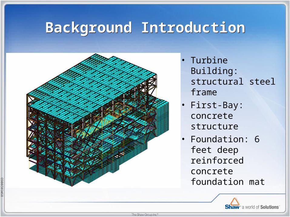
• Turbine Building: structural steel frame
• First-Bay: concrete structure
• Foundation: 6 feet deep reinforced concrete foundation mat

85M
1020
06D
Spring & Damper DeviceSpring & Damper Device
85M
1020
06D
Spring Pedestal Design Basis Spring Pedestal Design Basis
• Benefits of spring pedestal:• Seismic Isolation of TG• Vibration isolation of TG• Generic site design

85M
1020
06D
Spring DevicesSpring Devices
• Stiffness matrix is used to model each spring device. (Ref. GT STRUDL Vol.1 Section 2.1.9.2.4)
Horizontal spring matrix and Vertical spring matrix
GT STRUDL Input:

85M
1020
06D
Damper DevicesDamper Devices
• Viscous Damper Element is used to model the damper devices. (Ref. GT STRUDL Vol.3 Section 2.4.3.7)
GT STRUDL Input:
85M
1020
06D
Method discussionMethod discussion
• Method 1: Weighted Average Composite Modal Damping
• Method 2: Viscous Damper Element with Rayleigh Proportional damping
(Ref. GTStrudl Damping Models for Dynamic Analysis by Dr. Swanger)
85M
1020
06D
Method discussion (Method 1)Method discussion (Method 1)
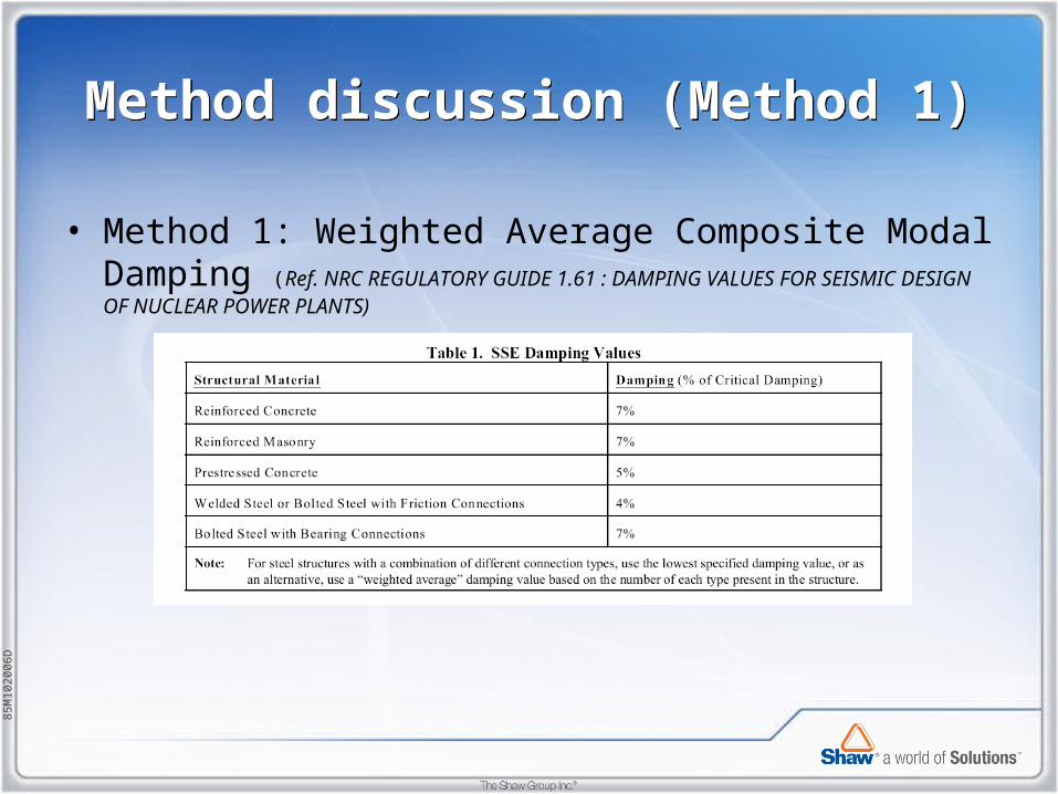
• Method 1: Weighted Average Composite Modal Damping (Ref. NRC REGULATORY GUIDE 1.61 : DAMPING VALUES FOR SEISMIC DESIGN OF NUCLEAR POWER PLANTS)

85M
1020
06D
Method discussion (Method 1)Method discussion (Method 1)
• Based on viscously damped free vibration (Ref. Dynamics of Structures Theory and applications to Earthquake Engineering, Second Edition, By Anil K. Chopra)
Therefore, ζ =

85M
1020
06D
Method discussion (Method 1)Method discussion (Method 1)
• Sample calculation:

85M
1020
06D
Method discussion (Method 1)Method discussion (Method 1)
GT STRUDL Input:
CONSTANT
MODAL DAMPING PROPORTIONAL TO STIFFNESS 0.04 MEMBERS… $ ( All Steel member)
MODAL DAMPING PROPORTIONAL TO STIFFNESS 0.07 MEMBERS… $ ( All Concrete member)
$ SPRING DAMPER
MODAL DAMPING PROPORTIONAL TO STIFFNESS 0.488 MEMBERS … $ (Horizontal springs)
MODAL DAMPING PROPORTIONAL TO STIFFNESS 0.226 MEMBERS … $ (Vertical springs)
……
……
……
……
COMPUTE MODAL DAMPING RATIOS AVERAGE BY ELEMENT
……
85M
1020
06D
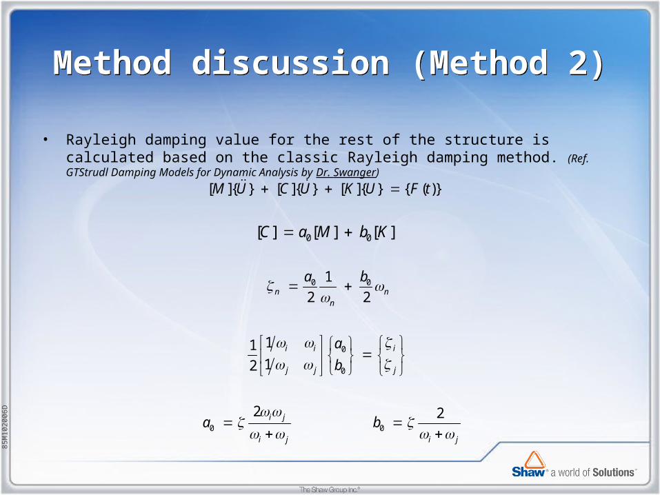
Method discussion (Method 2)Method discussion (Method 2)
• Rayleigh damping value for the rest of the structure is calculated based on the classic Rayleigh damping method. (Ref. GTStrudl Damping Models for Dynamic Analysis by Dr. Swanger)
0 0
0
0
0 0
0 0
[ ]{ } [ ]{ } [ ]{ } { ( )}
1
2 2
1112
2 2
[ ] [ ] [ ]
n nn
i i i
j j j
i j
i j i j
M U C U K U F t
a b
a
b
a b
C a M b K

85M
1020
06D
Method discussion (Method 2)Method discussion (Method 2)
GT STRUDL Input:
CONSTANT
DAMPING PROPORTIONAL TO STIFFNESS 3.36E-3 MASS 0.421
……
.......
……
COMPUTE MODAL DAMPING RATIOS PROPORTIONAL BY ELEMENT

85M
1020
06D
Response SpectrumResponse Spectrum
UBC 1997 Typical Design Response Spectrum - 5% of Critical Damping
Ref. "Fundamentals of Earthquake Engineering", Elnashai, Amr, and Di Sarno, Luigi-Wiley 2008, pp. 242.

85M
1020
06D
Response SpectrumResponse Spectrum

85M
1020
06D
Results (Mode Shape)Results (Mode Shape)

85M
1020
06D
Results (Mode Shape)Results (Mode Shape)

85M
1020
06D
Results (Mode Shape)Results (Mode Shape)

85M
1020
06D
Results (Model Damping)Results (Model Damping)

85M
1020
06D
Results (Displacement)Results (Displacement)
Method 1 Method 2
****SUMMARY OF MAXIMUM GLOBAL DISPLACEMENTS****
INDEPENDENT IN EACH COORDINATE
=============================================
* RESULT * MAXIMUM LOAD JOINT *
*========*==================================*
* X-DISP * 0.702437E+00 801 JCON685 *
* Y-DISP * 0.122054E+01 802 J2180072 *
* Z-DISP * 0.103463E+00 802 J2180128 *
=============================================
****SUMMARY OF MAXIMUM GLOBAL DISPLACEMENTS****
SRSS VECTOR LENGTHS
===============================================
* RESULT * MAXIMUM LOAD JOINT *
*==========*==================================*
* XYZ-DISP * 0.122351E+01 802 J2180072 *
* XY-DISP * 0.122350E+01 802 J2180072 *
* XZ-DISP * 0.702589E+00 801 JCON685 *
* YZ-DISP * 0.122055E+01 802 J2180072 *
===============================================
****SUMMARY OF MAXIMUM GLOBAL DISPLACEMENTS****
INDEPENDENT IN EACH COORDINATE
=============================================
* RESULT * MAXIMUM LOAD JOINT *
*========*==================================*
* X-DISP * 0.713116E+00 801 JCON685 *
* Y-DISP * 0.124141E+01 802 J2180072 *
* Z-DISP * 0.105379E+00 802 J2180128 *
=============================================
****SUMMARY OF MAXIMUM GLOBAL DISPLACEMENTS****
SRSS VECTOR LENGTHS
===============================================
* RESULT * MAXIMUM LOAD JOINT *
*==========*==================================*
* XYZ-DISP * 0.124452E+01 802 J2180072 *
* XY-DISP * 0.124451E+01 802 J2180072 *
* XZ-DISP * 0.713273E+00 801 JCON685 *
* YZ-DISP * 0.124141E+01 802 J2180072 *
===============================================

85M
1020
06D
Results (Force in Spring Device)Results (Force in Spring Device)
X-dir RS analysis results
Method 1 Method 2 DifferenceSpring X (kips) Y (kips) Z (kips) X (kips) Y (kips) Z (kips) X Y Z
SPR145 84.92769 166.0903 20.1795 86.36041 168.6277 20.83816 1.69% 1.53% 3.26%SPR146 76.60464 167.8068 20.19522 77.9763 170.368 20.85396 1.79% 1.53% 3.26%SPR147 69.07116 170.3578 20.21029 70.41343 172.9554 20.86907 1.94% 1.52% 3.26%SPR148 62.6656 173.8032 20.22734 64.01955 176.4508 20.88626 2.16% 1.52% 3.26%SPR149 83.82928 172.5399 20.16465 84.95311 175.2089 20.82179 1.34% 1.55% 3.26%SPR150 76.04088 175.2728 20.17146 77.05031 177.9861 20.82837 1.33% 1.55% 3.26%SPR151 69.10085 178.8727 20.1737 70.02023 181.6436 20.83029 1.33% 1.55% 3.25%SPR152 63.2779 183.4059 20.18252 64.14027 186.2487 20.83894 1.36% 1.55% 3.25%SPR153 96.38413 152.4591 11.00827 98.13284 154.7788 11.75312 1.81% 1.52% 6.77%SPR154 86.45916 145.0688 11.02513 88.03587 147.2773 11.77037 1.82% 1.52% 6.76%SPR155 79.16795 137.224 11.04941 80.60829 139.3142 11.7953 1.82% 1.52% 6.75%SPR156 73.36609 129.4854 11.0832 74.69064 131.4593 11.83 1.81% 1.52% 6.74%SPR157 68.52908 122.5437 11.11041 69.74251 124.4135 11.85799 1.77% 1.53% 6.73%SPR158 64.38567 116.5659 11.13073 65.48774 118.3466 11.87883 1.71% 1.53% 6.72%SPR159 53.11419 96.14936 9.548653 53.98523 97.62005 10.19062 1.64% 1.53% 6.72%SPR160 52.34111 93.61989 9.559899 53.16097 95.054 10.20257 1.57% 1.53% 6.72%

85M
1020
06D
Results (Force in Spring Device)Results (Force in Spring Device)
Y-dir RS analysis results
Method 1 Method 2 DifferenceSpring X (kips) Y (kips) Z (kips) X (kips) Y (kips) Z (kips) X Y Z
SPR145 137.1607 15.71322 103.7485 137.378 16.47342 104.8368 0.16% 4.84% 1.05%SPR146 172.0453 15.6656 103.6922 172.57 16.43277 104.7796 0.30% 4.90% 1.05%SPR147 210.6174 15.68163 103.6317 211.4759 16.4592 104.7181 0.41% 4.96% 1.05%SPR148 252.3571 15.77439 103.5863 253.5635 16.56603 104.6719 0.48% 5.02% 1.05%SPR149 145.9526 14.84497 103.2408 146.5848 15.61271 104.3224 0.43% 5.17% 1.05%SPR150 175.2781 14.59727 103.1109 176.0874 15.3747 104.1907 0.46% 5.33% 1.05%SPR151 208.0653 14.41078 102.9764 209.0803 15.20189 104.0542 0.49% 5.49% 1.05%SPR152 243.987 14.30544 102.8571 245.2268 15.11445 103.933 0.51% 5.66% 1.05%SPR153 212.0437 13.19826 157.106 212.9392 13.88156 159.0643 0.42% 5.18% 1.25%SPR154 195.7325 12.54095 157.143 196.7165 13.19012 159.1015 0.50% 5.18% 1.25%SPR155 178.732 11.85153 157.2147 179.7543 12.46498 159.1737 0.57% 5.18% 1.25%SPR156 161.5463 11.14822 157.3235 162.5731 11.72646 159.2836 0.64% 5.19% 1.25%SPR157 139.1629 10.47514 157.4232 140.107 11.02173 159.3846 0.68% 5.22% 1.25%SPR158 109.8577 9.83042 157.4845 110.6181 10.34962 159.4473 0.69% 5.28% 1.25%SPR159 67.44126 7.987501 135.1578 67.9031 8.415235 136.8419 0.68% 5.36% 1.25%SPR160 39.62578 7.627472 135.3078 39.87367 8.043455 136.9937 0.63% 5.45% 1.25%

85M
1020
06D
Results (Force in Damper Device)Results (Force in Damper Device)
Damper element force Calculation
Each mode V i = Via-Vib
By ABS method V = | |
Force: F = c * V
1
n
i
Vi

85M
1020
06D
Results (Force in Damper Device)Results (Force in Damper Device)
Damper element force Calculation
RMS Velocity Summary (ft/s) Force (Kips)
Damper
8001 8002 8001 8002Translational Translational Translational Translational
X Y Z X Y Z X Y Z X Y Z301 B/C 1.2781 0.0702 0.1645 0.0494 1.4394 0.2916 41.5981 2.283727 10.70552 1.606275 46.85112 18.98477302 B/C 1.2789 0.1091 0.1729 0.0497 1.4478 0.1892 41.62567 3.550266 11.25394 1.616197 47.12236 12.31534303 B/C 1.3170 0.1330 0.1657 0.0609 1.4466 0.3885 42.86446 4.327774 10.78769 1.981797 47.08411 25.28737304 B/C 1.4006 0.1364 0.1484 0.0561 1.4487 0.3751 45.58716 4.438926 9.660111 1.827078 47.15238 24.42012305 B/C 1.2974 0.0653 0.0491 0.0606 1.4317 0.3325 42.22641 2.124151 3.196387 1.971514 46.59743 21.64607306 B/C 1.3699 0.0648 0.0356 0.0567 1.4340 0.3252 44.5859 2.108344 2.318224 1.844394 46.67351 21.16749307 B/C 1.3189 0.0393 0.0061 0.0621 1.3284 0.3217 42.92867 1.278992 0.39847 2.02073 43.23613 20.94222308 B/C 1.3767 0.0404 0.0163 0.0578 1.3250 0.3232 44.8097 1.315764 1.061818 1.881824 43.12643 21.03635309 B/C 1.3615 0.0928 0.1233 0.0648 1.3168 0.3478 44.31391 3.018861 8.029522 2.108873 42.85931 22.64171310 B/C 1.4051 0.0869 0.1282 0.0602 1.3191 0.3618 45.73474 2.827555 8.342631 1.958478 42.9332 23.55273311 B/C 1.3765 0.1964 0.1586 0.0636 1.3665 0.3764 44.80201 6.391253 10.32483 2.069471 44.47535 24.50361312 B/C 1.3183 0.1961 0.1605 0.0623 1.3675 0.2209 42.90913 6.382413 10.44684 2.026559 44.50909 14.38076313 B/C 1.2619 0.1964 0.1725 0.0615 1.3608 0.2301 41.07138 6.390978 11.22698 2.001162 44.29008 14.97867314 B/C 1.3778 0.1968 0.1749 0.0552 1.3560 0.3900 44.84446 6.405455 11.38471 1.797755 44.13508 25.39017315 B/C 1.2760 0.1199 0.1141 0.0496 1.4473 0.3094 41.53274 3.90311 7.426821 1.613183 47.10706 20.13925316 B/C 1.2783 0.1085 0.1063 0.0495 1.4451 0.3032 41.60654 3.531925 6.921414 1.612604 47.0363 19.73456317 B/C 1.2795 0.1006 0.0986 0.0497 1.4449 0.2970 41.64592 3.274926 6.417931 1.616655 47.0273 19.33602318 B/C 1.2806 0.0934 0.0909 0.0497 1.4437 0.2909 41.6821 3.041447 5.915338 1.617384 46.991 18.93502319 B/C 1.2788 0.0744 0.0610 0.0495 1.4390 0.2672 41.62298 2.422986 3.968079 1.609694 46.83729 17.39469320 B/C 1.2773 0.0717 0.0532 0.0492 1.4370 0.2611 41.57415 2.333475 3.464846 1.602817 46.77042 16.99437

85M
1020
06D
ConclusionConclusion
• Spring device and damper device can be successfully modeled in GT STRUDL.
• Both methods give results consistent with each other.• To achieve more accurate results, time history analysis
needs to be performed.

85M
1020
06D
MathCad ApplicationMathCad Application
Benefits: Efficiency and Automation
• Generate load combination input file from Excel file.• Transform structural coordinates to move and rotate structure
geometry.• Offset mass distribution to create 5% torsional seismic effect for
response spectrum analysis.
85M
1020
06D
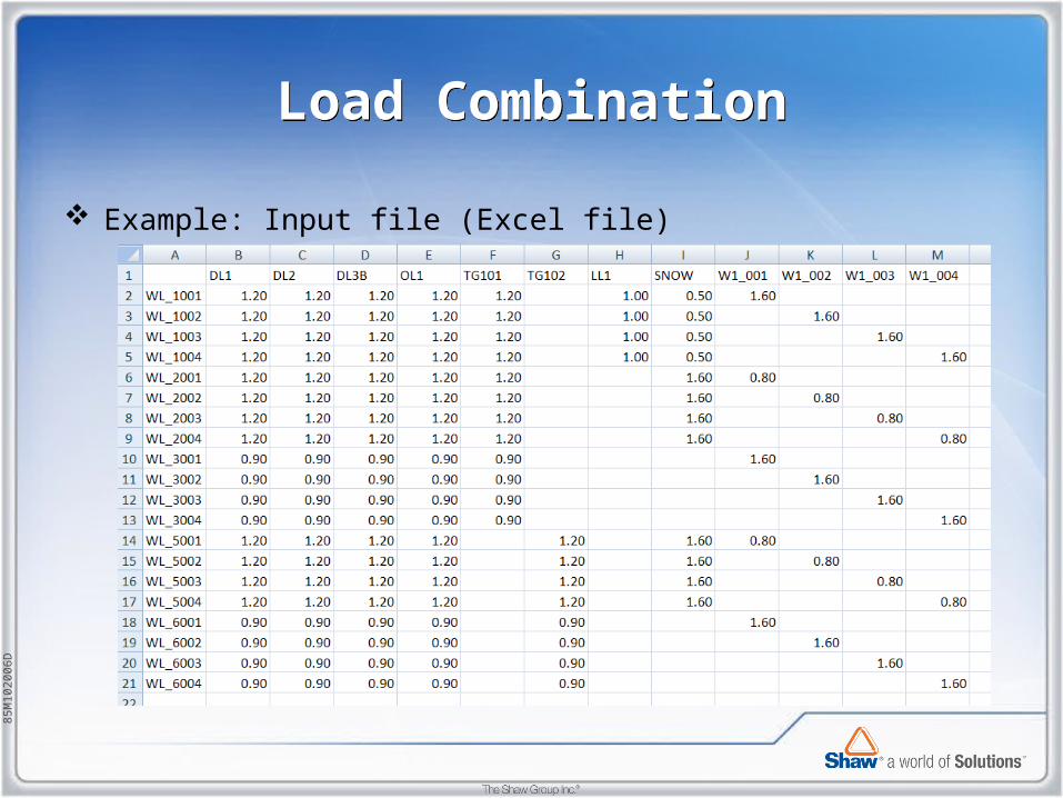
Load CombinationLoad Combination
Example: Input file (Excel file)

85M
1020
06D
Load CombinationLoad Combination
Example: MathCad file

85M
1020
06D
Load CombinationLoad Combination
Example: Output file (txt file)

85M
1020
06D
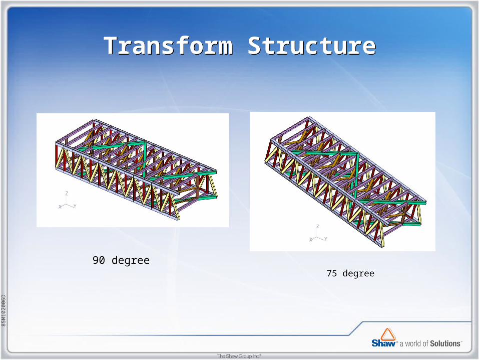
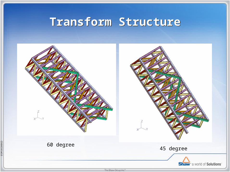
Transform StructureTransform Structure
Modular Stair Tower.pps Coordinate Transformation Function.html
Original purpose of using MathCAD to transform structure is to simulate the process of rigging and installing stair tower module. Same as the “MOVE OBJECT” command.
(Why not use “MOVE OBJECT” ? ) Later on, it is found this little program is very useful to transform any
structure and combine structures in different orientation and origins together.
85M
1020
06D
Transform StructureTransform Structure
75 degree
90 degree
85M
1020
06D
Transform StructureTransform Structure
45 degree60 degree

85M
1020
06D
Transform StructureTransform Structure
15 degree30 degree

85M
1020
06D
Transform StructureTransform Structure
Combine with TBStairs Module
85M
1020
06D
Torsional seismic effectTorsional seismic effect
The objective is to redistribute the structure's mass such that the requirements for accidental torsion are met.
At each level of the structure where it is desired to include accidental torsion, the mass will be re-distributed such that the new center of mass has been offset from its original position the required distance (normally 5% of the structures maximum dimension perpendicular to the direction of motion as code requirement).

85M
1020
06D
Torsional seismic effectTorsional seismic effect
• SEISMIC LOAD.html
• Input:JC2.xls
MASS DEAD2.xls
• Output:UBC-X-TOR.xls
UBC-Y-TOR.xls

85M
1020
06D
Torsional seismic effectTorsional seismic effect
85M
1020
06D
AcknowledgementsAcknowledgements
• The GT STRUDL analytical model used in this presentation is based on the Turbine Building for the Westinghouse AP1000 Advanced Passive Light Water Reactor Electric Power Generating Plant. Westinghouse Electric Company is the owner of the design. The original GT STRUDL analytical model was created by Toshiba Corporation/Obayashi Corporation in Japan. The design activity is being completed by Shaw under contract to Westinghouse.
• Dr. Michael Swanger
Computer Aided Structural Engineering Center (GTSTRUDL)Structural Engineering, Mechanics, and MaterialsGeorgia Institute of Technology

85M
1020
06D
ReferencesReferences
• GT STRUDL User Reference Manual• NRC REGULATORY GUIDE 1.61 • Dynamics of Structures Theory and applications to Earthquake
Engineering, Second Edition, Anil K. Chopra• GTStrudl Damping Models for Dynamic Analysis, Michael H.
Swanger, PhD• Fundamentals of Earthquake Engineering, Elnashai, Amr, and Di
Sarno, Luigi-Wiley 2008• UBC-1997

85M
1020
06D
Question ?Question ?