855GX IntelliBender Electric Bender - Platt Electric … 855GX Instructions.pdf · The Greenlee...
28
INSTRUCTION MANUAL 855GX IntelliBender ™ Electric Bender Read and understand all of the instructions and safety information in this manual before operating or servicing this tool. Register this product at www.greenlee.com 52055798 © 2010 Greenlee Textron Inc. 8/10 Patents Pending
Transcript of 855GX IntelliBender Electric Bender - Platt Electric … 855GX Instructions.pdf · The Greenlee...

INSTRUCTION MANUAL
855GX IntelliBender™
Electric Bender
Read and understand all of the instructions and safety information in this manual before operating or servicing this tool.
Register this product at www.greenlee.com52055798 © 2010 Greenlee Textron Inc. 8/10
Patents Pending

855GX Electric Bender
Greenlee / A Textron Company 4455 Boeing Dr. • Rockford, IL 61109-2988 USA • 815-397-70702
All specifications are nominal and may change as design improvements occur. Greenlee Textron Inc. shall not be liable for damages resulting from misapplication or misuse of its products.
IntelliBender is a trademark of Greenlee Textron Inc.
KEEP THIS MANUAL
Table of Contents
Description .................................................................... 2
Safety ............................................................................ 2
Purpose of this Manual ................................................. 2
Important Safety Information .....................................3–5
Grounding Instructions .................................................. 6
Specifications ................................................................ 6
Identification .................................................................. 7
Features ......................................................................... 8
Transporting Bender and Pivoting Bending Head .................................................. 9
Setup ........................................................................... 10
Operation ................................................................10–16
Basic Programmed Bending ....................................... 11
Manually Selecting Conduit Type and Size.............. 12
Basic Programmed Bending .................................... 12
Fully Programmed Bending ................................13–15
Optional PVC-Coated Conduit Bending .................. 15
Squeeze Adjustment ................................................ 16
Illustrated Bending Glossary ....................................... 17
Bending Instructions ..............................................18–19
Additional Bending Instructions .............................20–22
Additional Bending Tables ......................................23–26
Maintenance ................................................................ 27
Description
The Greenlee 855GX IntelliBender™ Electric Bender is intended to bend 1" to 2" conduit and pipe. This bender has the capability to accommodate the following types of conduit and pipe:
• Electrical Metallic Tubing
• Intermediate Metallic Conduit
• Rigid Conduit
• Aluminum Rigid
• PVC-Coated Rigid Conduit
• Schedule 40 Pipe
• Stainless Steel Rigid
The 855GX includes a shoe to bend EMT, IMC, and rigid conduit. In addition, shoes and roller supports are avail-able for bending PVC-coated conduit.
Safety
Safety is essential in the use and maintenance of Greenlee tools and equipment. This instruction manual and any markings on the tool provide information for avoiding hazards and unsafe practices related to the use of this tool. Observe all of the safety information provided.
Purpose of this Manual
This manual is intended to familiarize all personnel with the safe operation and maintenance procedures for the Greenlee 855GX Electric Bender.
Keep this manual available to all personnel.
Replacement manuals are available upon request at no charge at www.greenlee.com.
Do not discard this product or throw away! For recycling information, go to www.greenlee.com.

855GX Electric Bender
Greenlee / A Textron Company 4455 Boeing Dr. • Rockford, IL 61109-2988 USA • 815-397-70703
IMPORTANT SAFETY INFORMATION
SAFETY ALERT SYMBOL
This symbol is used to call your attention to hazards or unsafe practices which could result in an injury or property damage. The signal word, defined below, indicates the severity of the hazard. The message after the signal word provides information for pre-venting or avoiding the hazard.
Immediate hazards which, if not avoided, WILL result in severe injury or death.
Hazards which, if not avoided, COULD result in severe injury or death.
Hazards or unsafe practices which, if not avoided, MAY result in injury or property damage.
Read and understand all of the instructions and safety information in this manual before operating or servicing this tool.
Failure to observe this warning will result in severe injury or death.
Do not use this tool in a hazardous environment. Hazards include flam-mable liquids, gases, or other materi-als. Using this tool in a hazardous environment can result in a fire or explosion.
Failure to observe this warning will result in severe injury or death.
Electric shock hazard:
• Connect the power cord to a 120 volt, 20 amp receptacle on a ground fault protected circuit only. Refer to “Grounding Instructions.”
• Do not modify the power cord or plug.
• Inspect the power cord before use. Repair or replace the cord if damaged.
• Disconnect the unit from power before servicing.
Failure to observe this warning could result in severe injury or death.
For continued protection against risk of fire and electric shock, replace ONLY with same manufacturer, type, and rating of fuse. Refer to the “Maintenance” section of this manual.
Failure to observe this warning could result in severe injury or death.
• Do not use in dangerous environ-ment. Do not use power tools in damp or wet locations, or expose them to rain. Keep work area well lighted.
• Do not immerse the pendant switch in water or any other liquid.
Failure to observe these warnings could result in severe injury or death.
Always use safety glasses. Everyday glasses only have impact resistant lenses; they are NOT safety glasses. When using in dusty environment, use face or dust mask.
Failure to wear eye protection could result in serious eye injury from flying debris.
855GX Electric Bender
Greenlee / A Textron Company 4455 Boeing Dr. • Rockford, IL 61109-2988 USA • 815-397-70704
IMPORTANT SAFETY INFORMATION
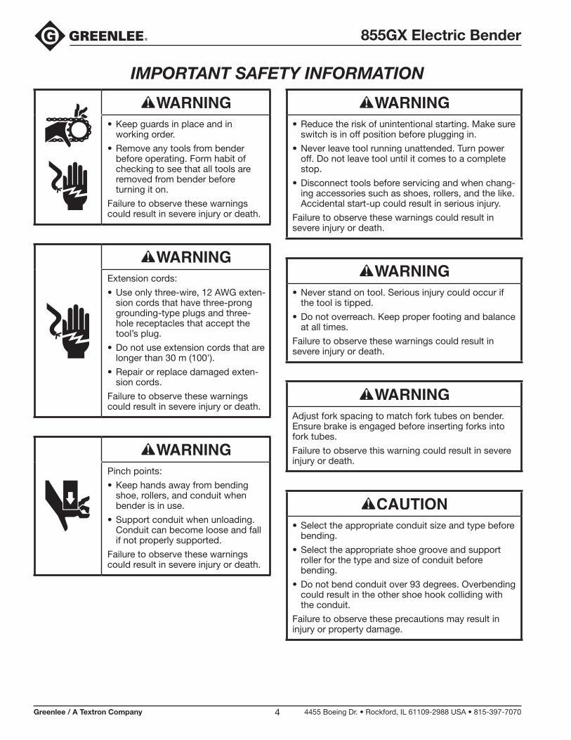
• Keep guards in place and in working order.
• Remove any tools from bender before operating. Form habit of checking to see that all tools are removed from bender before turning it on.
Failure to observe these warnings could result in severe injury or death.
Extension cords:
• Use only three-wire, 12 AWG exten-sion cords that have three-prong grounding-type plugs and three-hole receptacles that accept the tool’s plug.
• Do not use extension cords that are longer than 30 m (100').
• Repair or replace damaged exten-sion cords.
Failure to observe these warnings could result in severe injury or death.
Pinch points:
• Keep hands away from bending shoe, rollers, and conduit when bender is in use.
• Support conduit when unloading. Conduit can become loose and fall if not properly supported.
Failure to observe these warnings could result in severe injury or death.
• Reduce the risk of unintentional starting. Make sure switch is in off position before plugging in.
• Never leave tool running unattended. Turn power off. Do not leave tool until it comes to a complete stop.
• Disconnect tools before servicing and when chang-ing accessories such as shoes, rollers, and the like. Accidental start-up could result in serious injury.
Failure to observe these warnings could result in severe injury or death.
• Never stand on tool. Serious injury could occur if the tool is tipped.
• Do not overreach. Keep proper footing and balance at all times.
Failure to observe these warnings could result in severe injury or death.
Adjust fork spacing to match fork tubes on bender. Ensure brake is engaged before inserting forks into fork tubes.
Failure to observe this warning could result in severe injury or death.
• Select the appropriate conduit size and type before bending.
• Select the appropriate shoe groove and support roller for the type and size of conduit before bending.
• Do not bend conduit over 93 degrees. Overbending could result in the other shoe hook colliding with the conduit.
Failure to observe these precautions may result in injury or property damage.

855GX Electric Bender
Greenlee / A Textron Company 4455 Boeing Dr. • Rockford, IL 61109-2988 USA • 815-397-70705
IMPORTANT SAFETY INFORMATION
• Conduit moves rapidly as it is bent. The path of the conduit must be clear of obstructions. Be sure clearance is adequate before starting the bend.
• Wear proper apparel. Do not wear loose clothing, gloves, neckties, rings, bracelets, or other jewelry which may get caught in moving parts. Nonslip footwear is recommended. Wear protective hair covering to contain long hair.
• Do not force rollers or alter tool. It will do the job better and safer at the rate for which it was designed.
• Use right tool. Do not force tool or attachment to do a job for which it was not designed.
• Use this tool for the manufacturer’s intended purpose only. Use other than that which is instructed in this manual can result in injury or property damage.
Failure to observe these precautions may result in injury or property damage.
• Keep work area clean. Cluttered areas and benches invite accidents.
• Keep children away. All visitors should be kept safe distance from work area.
• Make workshop kid proof with padlocks, master switches, or by removing starter keys.
Failure to observe these precautions may result in injury or property damage.
• Inspect the bender before use. Replace worn, damaged, or missing parts with Greenlee replace-ment parts. A damaged or improperly assem-bled component could break and strike nearby personnel.
• Maintain tools with care. Keep tool clean for best and safest performance. Follow instructions for lubricating and changing accessories.
• Check damaged parts. Before further use of the tool, a guard or other part that is damaged should be carefully checked to determine that it will operate properly and perform its intended func-tion. Check for alignment of moving parts, binding of moving parts, breakage of parts, mounting, and any other conditions that may affect its operation. A guard or other part that is damaged should be properly repaired or replaced.
• Use recommended accessories. Consult the instruction manual for recommended accessories. The use of improper accessories may cause risk of injury to persons.
• Some bender parts and accessories are heavy and may require more than one person to lift and assemble.
Failure to observe these precautions may result in injury or property damage.
Note: Keep all decals clean and legible, and replace when necessary.

855GX Electric Bender
Greenlee / A Textron Company 4455 Boeing Dr. • Rockford, IL 61109-2988 USA • 815-397-70706
Grounding Instructions
Electric shock hazard:
• Do not modify the plug provided with the tool.
• Connect this tool to a grounded receptacle on a 20 amp ground fault protected circuit.
Failure to observe these warnings could result in severe injury or death.
This tool must be grounded. In the event of a malfunc-tion or breakdown, an electrical ground provides a path of least resistance for the electric current. This path of least resistance is intended to reduce the risk of electric shock.
This tool’s electric cord has a grounding conductor and a grounding plug as shown. Do not modify the plug. Connect the plug to a corresponding GFCI-protected receptacle that is properly installed and grounded in accordance with all national and local codes and ordinances.
Do not use an adapter.
20 Amp/120 Volt Plug and Receptacle
ReceptaclePlug
Do not modify the plug provided. If it will not fit the outlet, have the proper outlet installed by a qualified electrician. Improper connection of the equipment-grounding conductor can result in a risk of electric shock. The conductor with insulation having an outer surface that is green with or without yellow stripes is the equipment-grounding conductor. If repair or replacement of the electric cord or plug is necessary, do not connect the equipment-grounding conductor to a live terminal. Check with a qualified electrician or service personnel if the grounding instructions are not completely understood, or if in doubt as to whether the tool is properly grounded.
Specifications
Height (vertical bending position) ........................................................117.1 cm (46.1")
Width .....................................................................................................74.7 cm (29.4")
Depth (vertical bending position) ..............................................................84 cm (33.0")
Mass/Weight (bender with shoes and roller supports) ...........................230 kg (507 lb)
Power Supply .................................................................................... 120 VAC, 20 ampGFCI-protected receptacle
Operating Conditions
Temperature .......................................................... –20 °C to 49 °C (–5 °F to 120 °F)
Relative Humidity .................................................................................... 0% to 98%
Capacity ..................................................................1" to 2" conduit, schedule 40 pipe

855GX Electric Bender
Greenlee / A Textron Company 4455 Boeing Dr. • Rockford, IL 61109-2988 USA • 815-397-70707
Identification
Features 1. 1" to 2" shoe for EMT/IMC/rigid conduit 2. Main power (On-Off) switch/circuit breaker 3. Programmable bending selector buttons 4. LCD backlit display 5. 2" roller support 6. Conduit size determination trip lever 7. Bending head pivoting detent lock 8. Storage area 9. Fork tube10. Transport handle11. Swivel casters12. Roller support retainer13. 1" roller support14. Roller engagement handle15. 1-1/4" roller support16. 1-1/2" roller support17. Shoe retainer18. Lower pivot handle19. Hoist lifting bar20. Motor21. Roller support22. Squeeze adjuster23. Rear wheels24. Storage lid25. Storage lock tab26. Bending head pivot
27. Power cord with tie strap28. Pendent receptacle29. Brake30. USB port31. Upper pivot handle32. LCD shield33. Motor debris guard34. Gearbox35. Absolute encoder36. Squeeze roller release lever37. Fuse holder
DecalsA. BendingB. Circuit breakerC. Engage rollersD. 1" EMT/IMC rollerE. BrakeF. Fork tubeG. PivotH. SqueezeI. IdentificationJ. InstructionK. LiftingL. WarningM. Support releaseN. Fuse warningO. Raise rollers
117
16
35
15
14
12D13
C
O
30
A
7
G
B
8
332
N
4
2
5
6
92911
18
FE
10
26
2223
H
27 2136
34M
33
20
24
25
28
L
J
I
K
19
31
37
Squeeze rollersillustrated inraised/engaged position.

855GX Electric Bender
Greenlee / A Textron Company 4455 Boeing Dr. • Rockford, IL 61109-2988 USA • 815-397-70708
Features
• Single shoe bending of 1" to 2" EMT, IMC, and rigid conduit.
• 1/2" to 2" PVC-coated conduit bending capability with optional shoe group.
• Four large wheels for easy transportability.
• Waist level working height.
• Patented roller system automatically adjusts between IMC and EMT conduit.
• Patent pending conduit size and type sensing system allows for quick loading and bending to desired angle.
• No homing or initial setup required—just load conduit and bend.
• Bender automatically compensates for springback—simply bend to the desired angle.
• Squeeze adjustment allows for variations in conduit.
• Bright, adjustable contrast LCD display for easy programmable bending input and dimensional illustra-tions for making marks on conduit.
• Programmable memory will stop bender at any pro-grammed angle.
• Common angles preset with one-touch selection.
• Digital display shows bend angle on pendant.
• Computer will provide alignment mark dimensions for stubs, kicks, offsets, three- and four-bend saddles, and U-bends for any height, length, and angle. Programmed for transfer to other 855GX benders. Programmed bends can also be uploaded to bender from bends programmed on a computer. Bends can be saved on thumb drive through USB port.
• Removable patent pending pendant prevents unauthorized use of bender. Pendant includes cord strain relief and strong rare earth magnets for holding on steel surfaces.
• Lockable storage area for pendant, instruction manual, etc.
• Lifting bar provided for easy hoisting.
• Fork tubes provided for easy forklift mobility.
• Adjustable height handle for easy and comfortable mobility.
• Rear wheel brake to securely keep bender in place during use.
• Quick release retainers for bending shoe and rollers.
• Quick release lock pin to easily pivot bender between vertical and horizontal positions.

855GX Electric Bender
Greenlee / A Textron Company 4455 Boeing Dr. • Rockford, IL 61109-2988 USA • 815-397-70709
Refer to the “Identification” section of this manual.
To transport the bender on the ground:
1. Pivot the bending head to the horizontal bending position.
2. Push down on the lower pivot handle (18) to remove the preload from the detent pin while pulling the detent pin (7) out.
3. Rotate the bending head as shown below until it locks in the horizontal position.
4. Remove the handle locking pins and raise the handle to the desired height.
5. Reverse steps 1 through 4 to return the bending head to its vertical position.
To transport the bender with a forklift:
Insert the forks into the fork tubes (9) and lift.
Adjust fork spacing to match fork tubes on bender. Ensure brake is engaged before inserting forks into fork tubes.
Failure to observe this warning could result in severe injury or death.
To transport the bender with a crane:
1. Pivot the bending head to the vertical bending position.
2. Confirm that the shoe and roller support retainers (12, 17) are in place and locked.
3. Use a sling around the lifting bar (19) to support the full weight. DO NOT USE HANDLES. Lift only with the head in the vertical position.
Transporting Bender and Pivoting Bending Head

855GX Electric Bender
Greenlee / A Textron Company 4455 Boeing Dr. • Rockford, IL 61109-2988 USA • 815-397-707010
Setup
Always use safety glasses. Everyday glasses only have impact resistant lenses; they are NOT safety glasses. When using in dusty environment, use face or dust mask.
Failure to wear eye protection could result in serious eye injury from flying debris.
Refer to the “Identification” section of this manual.
1. Position the bender so that there is room to load conduit and engage the rear wheel brake bar.
2. Place the bender in the desired vertical or horizontal bending position.
3. Plug the bender into a grounded 20 amp outlet.
4. Plug the pendant switch into the pendant receptacle (28).
Operation
Do not use this tool in a hazardous environment. Hazards include flam-mable liquids, gases, or other materi-als. Using this tool in a hazardous environment can result in a fire or explosion.
Failure to observe this warning will result in severe injury or death.
Electric shock hazard:
• Connect the power cord to a 120 volt, 20 amp receptacle on a ground fault protected circuit only. Refer to “Grounding Instructions.”
• Do not modify the power cord or plug.
• Inspect the power cord before use. Repair or replace the cord if damaged.
• Disconnect the unit from power before servicing.
Failure to observe this warning could result in severe injury or death.
Pinch points:
• Keep hands away from bending shoe, rollers, and conduit when bender is in use.
• Support conduit when unloading. Conduit can become loose and fall if not properly supported.
Failure to observe these warnings could result in severe injury or death.
Disconnect tools before servicing and when chang-ing accessories such as shoes, rollers, and the like. Accidental start-up could result in serious injury.
Failure to observe this warning could result in severe injury or death.

855GX Electric Bender
Greenlee / A Textron Company 4455 Boeing Dr. • Rockford, IL 61109-2988 USA • 815-397-707011
Wear proper apparel. Do not wear loose clothing, gloves, neckties, rings, bracelets, or other jewelry which may get caught in moving parts. Nonslip foot-wear is recommended. Wear protective hair covering to contain long hair.
Failure to observe this precaution may result in injury or property damage.
Refer to the “Identification” section of this manual.
1. Turn on the main power switch (2).
2. Use the BEND or UNLOAD button to orient the shoe so that the hooks of the conduit type to be bent are around the 5 o’clock (approximately –5°) position. (Silver hooks are for EMT; green hooks are for IMC and rigid.)
3. Load the conduit so that the bending mark is aligned with the front edge of the hook.
4. Bend the conduit.
a. For 1-1/4", 1-1/2", and 2" EMT or IMC conduit, use the roller engagement handle (14) to raise the rollers from the retracted position to the upright (engaged) position, as shown below.
Squeeze Rollers Retracted Squeeze Rollers Engaged
Note: Lifting the tail of a long stick of conduit will aid in engaging the rollers. The cam should hold the rollers in the upright position, as shown below.
Note: To retract the rollers without bending once the cam locks them in place, pump the lever below the 2" split roller several times. Press BEND while applying pressure to the roller engagement handle until the rollers hit their stop.
Squeeze RollerRelease Lever
b. For all other conduit, press BEND while making sure the bend mark stays at the front of the hook until the conduit contacts the tail roller. If bending 1" IMC, rotate the support roller so that the IMC roller is up.
5. Continue to press BEND until reaching the desired bend angle shown in the pendant display. The dis-played angle in the pendant and on the LCD display will be the angle of the bend after the conduit springs back (subject to variations in conduit). Use BEND or JOG to sneak up on an angle. JOG will advance the shoe about 1/2°.
6. Press UNLOAD to free the conduit.
7. Twist the conduit to release it from the hook and remove it from the shoe.
UNLOAD
BEND
JOG
CLEAR
ANGLESELECT
ANGLESELECT
Operation (cont’d)

855GX Electric Bender
Greenlee / A Textron Company 4455 Boeing Dr. • Rockford, IL 61109-2988 USA • 815-397-707012
Manually Selecting Conduit Type and SizeThe 855GX can automatically detect EMT, IMC, and rigid conduit as well as determine 1", 1-1/4", 1-1/2", and 2" conduit sizes. When bending with these types of conduit, using auto mode is recommended. However, in some cases you may want to manually set the bender for the type of conduit being used (for example, PVC-coated rigid conduit).
To manually set the bender, follow these steps:
1. From the home screen, press the button next to “SET UP”.
2. From the setup screen, press the button next to “MAN SET”.
3. Select the conduit type to be used. (Selecting “AUTO” returns the bender to auto mode, where the type is automatically detemined.)
4. Press NEXT to advance to the screen to select the conduit size.
5. Select the conduit size to be used. (Selecting “AUTO” returns the bender to auto mode, where the size is automatically detemined.)
6. Press NEXT to go back to the setup screen, or to go back to the home screen.
Basic Programmed BendingYou can preset an angle into the computer memory and the bender will automatically stop at that angle.
Note: Angle will be with springback factored in.
1. Select the angle.
a. Use ANGLE SELECTp or ANGLE SELECTq on the pendant to change the programmed angle. A single press changes the angle by 1°. Holding down an ANGLE SELECT key changes the angle rapidly in 5° increments. Pressing CLEAR resets the programmed angle back to 0°. This angle will stay in the memory until CLEAR is pressed, a new angle is selected, or the power is turned off.
b. Use one of the common angles displayed in the LCD display (4). To select an angle by this method, press the selector button (3) next to the desired angle shown in the display. This angle will stay in the memory until CLEAR is pressed, a new angle is selected, or the power is turned off.
The programmed angle will remain in the pendant display for about two seconds and then revert to the current shoe position. The programmed angle can also be viewed on the LCD home screen in the “STOP ANGLE” box.
2. Press BEND until the bender stops. The bender may start to slow down before reaching the selected angle. This is normal. After the bender stops at the programmed bend, releasing and repressing the BEND button allows the bender to continue bending.
Operation (cont’d)
855GX Electric Bender
Greenlee / A Textron Company 4455 Boeing Dr. • Rockford, IL 61109-2988 USA • 815-397-707013
Operation (cont’d)
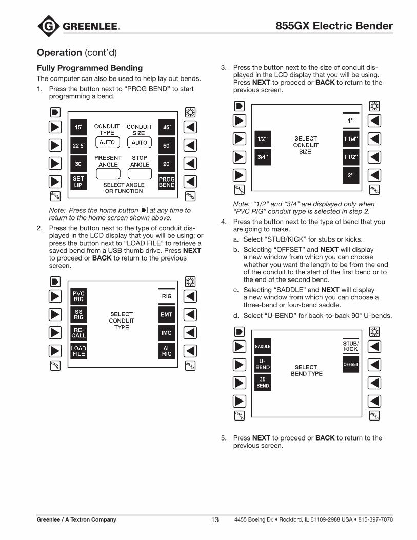
Fully Programmed BendingThe computer can also be used to help lay out bends.
1. Press the button next to “PROG BEND” to start programming a bend.
SELECT ANGLEOR FUNCTION
Note: Press the home button at any time to return to the home screen shown above.
2. Press the button next to the type of conduit dis-played in the LCD display that you will be using; or press the button next to “LOAD FILE” to retrieve a saved bend from a USB thumb drive. Press NEXT to proceed or BACK to return to the previous screen.
3. Press the button next to the size of conduit dis-played in the LCD display that you will be using. Press NEXT to proceed or BACK to return to the previous screen.
Note: “1/2” and “3/4” are displayed only when “PVC RIG” conduit type is selected in step 2.
4. Press the button next to the type of bend that you are going to make.
a. Select “STUB/KICK” for stubs or kicks.
b. Selecting “OFFSET” and NEXT will display a new window from which you can choose whether you want the length to be from the end of the conduit to the start of the first bend or to the end of the second bend.
c. Selecting “SADDLE” and NEXT will display a new window from which you can choose a three-bend or four-bend saddle.
d. Select “U-BEND” for back-to-back 90° U-bends.
5. Press NEXT to proceed or BACK to return to the previous screen.

855GX Electric Bender
Greenlee / A Textron Company 4455 Boeing Dr. • Rockford, IL 61109-2988 USA • 815-397-707014
6. Input the dimensions of the bend.
Stubs and kicks:
Press the button next to “HT” (height) if it is not already highlighted with an asterisk. Use the buttons next to +# and –$ to increase or decrease the height until it is to the desired value. A single press of the button will change the value by 1/8". Holding the button down will rapidly change the values. Press the button next to “A” (angle). Select the desired angle as above. The angle changes in 1/2° increments.
Offsets:
Press the button next to “HT” (height) if it is not already highlighted with an asterisk. Use the buttons next to +# and –$ to increase or decrease the height until it is to the desired value. A single press of the button will change the value by 1/8". Holding the button down will rapidly change the values. Press the button next to “L” (length). Select the desired length as above. The length changes in 1/8" incre-ments. Press the button next to “A” (angle). Select the desired angle as above. The angle changes in 1/2° increments.
Saddles:
Press the button next to “HT” (height) if it is not already highlighted with an asterisk. Use the buttons next to +# and –$ to increase or decrease the height until it is to the desired value. A single press of the button will change the value by 1/8". Holding the button down will rapidly change the values. Press the button next to “L” (length). Select the desired length as above. The length changes in 1/8" incre-ments. Press the button next to “A” (angle). Select the desired angle as above. The angle changes in 1/2° increments.
U-bends:
Press the button next to “HT” (height) if it is not already highlighted with an asterisk. Use the buttons next to +# and –$ to increase or decrease the height until it is to the desired value. A single press of the button will change the value by 1/8". Holding the button down will rapidly change the values. Press the button next to “L” (length). Select the desired length as above. The length changes in 1/8" increments.
3D bends:
A 3D bend is the same as an offset bend, except there is an additional change of direction right and/or left. Input the desired height by pressing the button next to “HT” if it is not already highlighted with an asterisk. Use the buttons next to +# and –$ to increase or decrease the height value. A single
press of the button will change the height by 1/8". Holding the button down will rapidly change the values. Select the rise angle by pressing the button next to “A”. Select the angle value as above. The angle changes in 1/2° increments.
HTA
Select the horizontal bend angles by pressing the button next to “H1” and adjusting the value as above; repeat for the “H2” button. The horizontal angles are as viewed from directly above. Refer to the “Top Views of Bends” illustration below for examples. Positive angles represent bends to the right. Negative angles represent bends to the left.
Select the length by pressing the button next to “L”. Select the value for “L” as above. All values for “L” are to the centerline of the conduit. The length is defined as where the sight lines of the first and third legs intersect each other to the end of the conduit, as viewed from directly above. Refer to the following illustrations for examples.
LL
L
L
L
L
H1 = 45°H2 = 90°
H1 = 90°H2 = 90°
H1 = 60°H2 = 30°
H1 = 45°H2 = 0° L = ∞
H1 = 30°H2 = –60°
H1 = –45°H2 = –60°
Top Views of Bends
Operation (cont’d)
Fully Programmed Bending (cont’d)
855GX Electric Bender
Greenlee / A Textron Company 4455 Boeing Dr. • Rockford, IL 61109-2988 USA • 815-397-707015
Operation (cont’d)
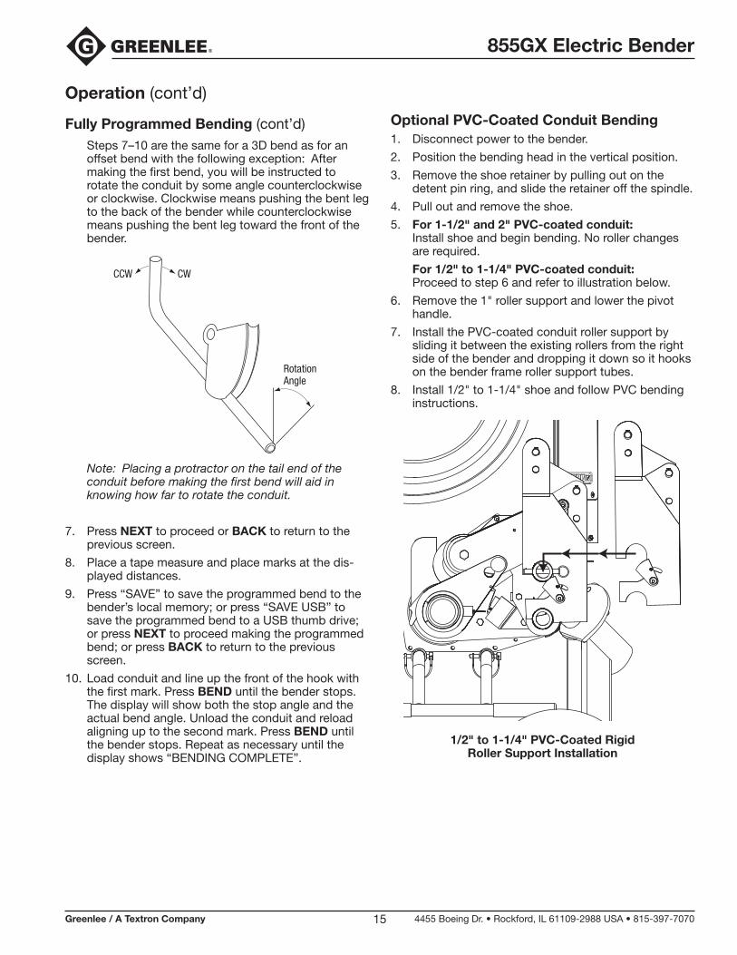
Fully Programmed Bending (cont’d) Steps 7–10 are the same for a 3D bend as for an
offset bend with the following exception: After making the first bend, you will be instructed to rotate the conduit by some angle counterclockwise or clockwise. Clockwise means pushing the bent leg to the back of the bender while counterclockwise means pushing the bent leg toward the front of the bender.
RotationAngle
CCW CW
Note: Placing a protractor on the tail end of the conduit before making the first bend will aid in knowing how far to rotate the conduit.
7. Press NEXT to proceed or BACK to return to the previous screen.
8. Place a tape measure and place marks at the dis-played distances.
9. Press “SAVE” to save the programmed bend to the bender’s local memory; or press “SAVE USB” to save the programmed bend to a USB thumb drive; or press NEXT to proceed making the programmed bend; or press BACK to return to the previous screen.
10. Load conduit and line up the front of the hook with the first mark. Press BEND until the bender stops. The display will show both the stop angle and the actual bend angle. Unload the conduit and reload aligning up to the second mark. Press BEND until the bender stops. Repeat as necessary until the display shows “BENDING COMPLETE”.
Optional PVC-Coated Conduit Bending1. Disconnect power to the bender.
2. Position the bending head in the vertical position.
3. Remove the shoe retainer by pulling out on the detent pin ring, and slide the retainer off the spindle.
4. Pull out and remove the shoe.
5. For 1-1/2" and 2" PVC-coated conduit:Install shoe and begin bending. No roller changes are required.
For 1/2" to 1-1/4" PVC-coated conduit: Proceed to step 6 and refer to illustration below.
6. Remove the 1" roller support and lower the pivot handle.
7. Install the PVC-coated conduit roller support by sliding it between the existing rollers from the right side of the bender and dropping it down so it hooks on the bender frame roller support tubes.
8. Install 1/2" to 1-1/4" shoe and follow PVC bending instructions.
1/2" to 1-1/4" PVC-Coated Rigid Roller Support Installation

855GX Electric Bender
Greenlee / A Textron Company 4455 Boeing Dr. • Rockford, IL 61109-2988 USA • 815-397-707016
Operation (cont’d)
Squeeze AdjustmentSqueeze is factory set and should not normally need to be adjusted.
When bending 1-1/4", 1-1/2", or 2" EMT or IMC, the amount of squeeze applied to the conduit can be adjusted to compensate for conduit variations. The squeeze is set properly if the support shaft does not contact the support plates while bending EMT, as shown by the shaded parts below. The shaft should not be more than approximately 1/4" (6 mm) above the lower flat surface.
Squeeze can be checked by loading EMT conduit and advancing the shoe until conduit starts to bend. If support shafts touch plates or are more than 1/4" (6 mm) from plates, unload conduit and adjust squeeze as described.
• If shaft is touching, increase squeeze.
• If shaft is farther than 1/4" (6 mm), decrease squeeze.
1/4" (6 mm) max. gap between shaft and top of side plates
To adjust the squeeze:
1. Unplug the bender.
2. Remove screw (refer to illustration below).
3. Rotate the squeeze adjuster:
• If the shaft is contacting the support plates, increase the squeeze by rotating the squeeze adjuster clockwise.
• If the shaft is too high above the support plates, decrease the squeeze by rotating the squeeze adjuster counterclockwise.
INCREASE
DECREASE
Squeeze Adjuster Holding Screw
855GX Electric Bender
Greenlee / A Textron Company 4455 Boeing Dr. • Rockford, IL 61109-2988 USA • 815-397-707017
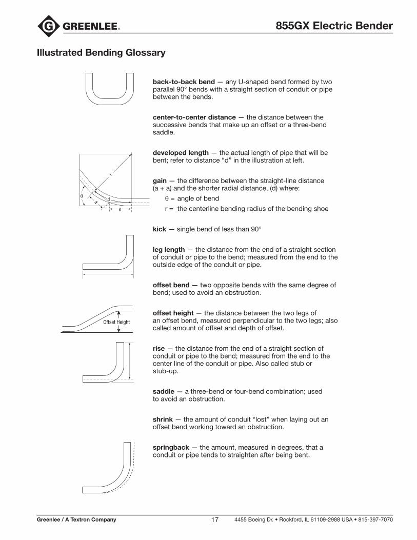
Illustrated Bending Glossary
back-to-back bend — any U-shaped bend formed by two parallel 90° bends with a straight section of conduit or pipe between the bends.
center-to-center distance — the distance between the successive bends that make up an offset or a three-bend saddle.
developed length — the actual length of pipe that will be bent; refer to distance “d” in the illustration at left.
gain — the difference between the straight-line distance(a + a) and the shorter radial distance, (d) where:
q = angle of bend
r = the centerline bending radius of the bending shoe
kick — single bend of less than 90°
leg length — the distance from the end of a straight section of conduit or pipe to the bend; measured from the end to the outside edge of the conduit or pipe.
offset bend — two opposite bends with the same degree of bend; used to avoid an obstruction.
offset height — the distance between the two legs of an offset bend, measured perpendicular to the two legs; also called amount of offset and depth of offset.
rise — the distance from the end of a straight section of conduit or pipe to the bend; measured from the end to the center line of the conduit or pipe. Also called stub or stub-up.
saddle — a three-bend or four-bend combination; used to avoid an obstruction.
shrink — the amount of conduit “lost” when laying out an offset bend working toward an obstruction.
springback — the amount, measured in degrees, that a conduit or pipe tends to straighten after being bent.
a
a
d
r
Offset Height
855GX Electric Bender
Greenlee / A Textron Company 4455 Boeing Dr. • Rockford, IL 61109-2988 USA • 815-397-707018
Bending Instructions90° STUBS
1. Measure the length of the required stub.
2. Refer to the Minimum Stub Length formula on the Deduct Table. The required stub must be equal to or longer than the Minimum Stub Length.
3. Measure and mark the stub length on the conduit. This is Mark 1. Subtract the Deduct from this mark and make a new mark. This is Mark 2.
4. Align Mark 2 with the front edge of the hook and bend the conduit.
Note: The shoe bends to 90° maximum.
STUB LENGTH
DEDUCT MARK 2
MARK 2
MARK 1
MARK 1
STU
B LE
NG
TH
Deduct Table
CONDUIT SIZE 1 1-1/4 1-1/2 2
DEDUCT
STEEL RIGID 11-7/8 14-3/8 15-3/8 16-5/8
EMT 11-7/8 14-3/8 15-3/8 16-7/8
IMC 11-7/8 14-3/8 15-3/8 16-5/8
ALUM. RIGID 11-7/8 14-3/8 15-3/8 16-5/8
MINIMUM STUB LENGTH = DEDUCT PLUS 2 INCHES
Figures are approximate
855GX Electric Bender
Greenlee / A Textron Company 4455 Boeing Dr. • Rockford, IL 61109-2988 USA • 815-397-707019
Offsets
1. Measure the height and length of the obstruction. Select the angle to be used.
2. Refer to the Offset Table. The height of the obstruc-tion must be equal to or greater than the minimum offset.
3. Refer to the X Table to find the X dimension. Refer to the Offset Table to find the center-to-center distance.
Note: If the center-to-center distance is not shown, calculate it by using the multipliers shown in the Offset Table.
4. Mark the conduit as shown.
5. Insert the conduit into the bender. Align Mark 1 with the front edge of the hook and bend the conduit.
6. Align Mark 2 with the front edge of the hook. Without removing the conduit from the bender, rotate the conduit 180°. Make the second bend.
LENGTH
HEIGHT
LENGTH
MARK 1 MARK 2CENTER TO CENTER
DISTANCE
X
OBSTRUCTION
Offset Table
Finished Angle
OFFSET
15° 30° 45°
Max. Conduit
Size
Center-to-Center
Max. Conduit
Size
Center-to-Center
Max. Conduit
Size
Center-to-Center
2 1-1/4 7-3/4
4 2 15-7/16 1 7-15/16
6 2 23-3/16 2 11-15/16
8 2 30-15/16 2 15-15/16 1 11-5/16
10 2 38-5/8 2 19-15/16 2 14-1/8
12 2 46-3/8 2 23-15/16 2 16-15/16
14 2 54-1/16 2 27-15/16 2 19-13/16
16 2 61-13/16 2 31-15/16 2 22-5/8
18 2 69-9/16 2 35-15/16 2 25-7/16
20 2 77-1/4 2 39-15/16 2 28-1/4
22 2 85 2 43-15/16 2 31-1/8
CENTER-TO-CENTER DISTANCE = OFFSET HEIGHT x MULTIPLIER
OFFSET ANGLE 10° 15° 22-1/2° 30° 45°
MULTIPLIER 5.8 3.9 2.6 2.0 1.4
Figures are approximate
X Table
CONDUIT SIZE 1 1-1/4 1-1/2 2
“X” 4-1/16 5-1/16 5-13/16 6-1/8
Figures are approximate
Centerline Bending Radii
SHOE SIZEEMT IMC/RIGID
in mm in mm1 7 177.8 6-15/16 176.2
1-1/4 8-13/16 223.8 8-3/4 222.3
1-1/2 8-3/8 212.7 8-1/4 209.6
2 9-1/4 235.0 9 228.6
Bending Instructions (cont’d)

855GX Electric Bender
Greenlee / A Textron Company 4455 Boeing Dr. • Rockford, IL 61109-2988 USA • 815-397-707020
The following drawings and bending tables are intended to provide the information necessary to accomplish the most common types of bends. The bending tables contain conduit marking information.
STUBS
1. Select the size and type of conduit. Determine the height of stub and the angle to be used.
2. Find the table that corresponds to the size and type of conduit selected in Step 1.
3. Under the column labeled ANGLE, find the appro-priate angle.
4. Find the row labeled Y. In the row at the top of the page, find the height (H) of the stub. The number shown at the intersection of row Y and column H is the distance Y. Place the bending mark Y inches from the end of the conduit.
5. Bend the conduit.
Y
HEIGHT
MARK
ANGLE
Additional Bending InstructionsOFFSETS
An offset is used to route the conduit around an obstruction. To make an offset, two equal bends are required. The distance between the two bends is the center-to-center distance.
When working past an obstruction, it is necessary to determine the location of the first bend. The center-to-center distance is then used to determine the location of the second bend. When working toward an obstruction, it is necessary to determine the location of the second bend. The center-to-center distance is then used to determine the location of the first bend.
Working Past an Obstruction
1. Select the size and type of conduit. Measure the height of the obstruction and the distance labeled LENGTH. Determine the angle to be used.
2. Find the table that corresponds to the size and type of conduit selected in Step 1.
3. To the right of the size and type of conduit, find the dimension labeled X. Subtract X from LENGTH. Place the first bending mark this distance from the end of the conduit.
4. Under the column labeled ANGLE, find the appro-priate angle. Find the row labeled L1. In the row at the top of the page, find the height (H) of the offset. The number shown at the intersection of row L1 and column H is L1. Place the second bending mark L1 inches from the first bending mark.
5. Bend the conduit.
L1LENGTH – X
LENGTH
HEIGHT
START OFFIRSTBEND
MARK 1 MARK 2
ANGLEOBSTRUCTION

855GX Electric Bender
Greenlee / A Textron Company 4455 Boeing Dr. • Rockford, IL 61109-2988 USA • 815-397-707021
Additional Bending Instructions (cont’d)Working Toward an Obstruction
1. Select the size and type of conduit. Measure the height of the obstruction and the distance labeled LENGTH TO END OF SECOND BEND. Determine the angle to be used.
2. Find the table that corresponds to the size and type of conduit selected in Step 1.
3. Under the column labeled ANGLE, find the appro-priate angle. Find the row labeled Z. In the row at the top of the page, find the height (H) of the offset. The number shown at the intersection of the Z row and the H column is Z. Subtract Z from LENGTH TO THE END OF SECOND BEND. Place the first bending mark this distance from the end of the conduit.
4. In the same column, find the row labeled L1. Place the second bending mark L1 inches from the first bending mark.
5. Bend the conduit.
L1LENGTH – Z
LENGTH TO END OF SECOND BEND
HEIGHT
MARK 1 MARK 2
ANGLE
THREE-BEND SADDLE
1. Select the size and type of conduit. Measure the height of the obstruction and the distance from the end of the conduit to the center (LENGTH TO CENTER) of the bend. Determine the angle to be used.
2. Find the table that corresponds to the size and type of conduit selected in Step 1.
3. Under the column labeled ANGLE, find the appro-priate angle. Find the row labeled Z. In the row at the top of the page, find the height (H) of the offset. The number shown at the intersection of the Z row and the appropriate H column is Z. Subtract Z from the LENGTH TO CENTER. Place the first bending mark this distance from the end of the conduit.
4. In the same column, find the row labeled L1. Place the second bending mark L1 inches from the first bending mark.
5. In the same column, find the row labeled L2. Place the third bending mark L2 inches from the second bending mark.
6. Bend the conduit.
L1LENGTH – Z
LENGTH TO CENTER
MARK 1 MARK 2 MARK 3
L2
ANGLEHEIGHT
855GX Electric Bender
Greenlee / A Textron Company 4455 Boeing Dr. • Rockford, IL 61109-2988 USA • 815-397-707022
Additional Bending Instructions (cont’d)FOUR-BEND SADDLE
1. Select the size and type of conduit. Measure the height of the obstruction, the distance labeled LENGTH, and the distance labeled STRAIGHT SECTION. Determine the angle to be used.
2. Find the table that corresponds to the size and type of conduit selected in Step 1.
3. Under the column labeled ANGLE, find the appropri-ate angle. Find the row labeled Z. In the row at the top of the page, find the height (H) of the offset. The number shown at the intersection of the Z row and the appropriate H column is Z. Subtract Z from the LENGTH. Place the first bending mark this distance from the end of the conduit.
4. In the same column, find the row labeled L1. Place the second bending mark L1 inches from the first bending mark.
5. In the same column, find the row labeled L2. Add L2 to the STRAIGHT SECTION. Place the third bending mark this distance from the first bending mark.
6. Make the final bending mark L1 inches from the third bending mark.
7. Bend the conduit.
LENGTH – Z
MARK 1 MARK 2 MARK 3
L2 + STRAIGHT SECTION
HEIGHT
STRAIGHTSECTION
MARK 4
LENGTH
L1 L1
ANGLE
U-BENDS
1. Select the size and type of conduit. Determine the LENGTH and the HEIGHT.
2. Find the table that corresponds to the size and type of conduit selected in Step 1.
3. Under the column labeled ANGLE, find 90°.
4. Find the row labeled Y. In the row at the top of the page, find the height (H) that corresponds to the LENGTH. The number shown at the intersection of the Y row and the appropriate H column is the dis-tance Y. Place the bending mark Y inches from the end of the conduit.
5. Find the row labeled L1, and go to the right to find the height (H) that corresponds to the HEIGHT.
6. The number shown at the intersection of the L1 row and the appropriate H column is L1. Place the second bending mark L1 inches from the first mark.
7. Bend the conduit.
Y
MARK 1 MARK 2
L1
LENGTH
HEIGHT

855GX Electric Bender
Greenlee / A Textron Company 4455 Boeing Dr. • Rockford, IL 61109-2988 USA • 815-397-707023
Additional Bending Tables DIM ANGLE 2" 4" 6" 8" 10" 12" 15" 18" 24" 36"
1" EMT Y 15 0.49 8.22 15.94 23.67 31.40 39.13 50.72 62.31 85.49 131.85 L1 15 7.72 15.44 23.17 30.90 38.63 46.35 57.94 69.54 92.72 139.08 L2 15 9.61 17.34 25.06 32.79 40.52 48.25 59.84 71.43 94.61 140.98 Z 15 13.41 20.87 28.34 35.80 43.27 50.73 61.93 73.12 95.51 140.30MINIMUM H = 1.54 Y 22.5 3.45 8.68 13.91 19.13 24.36 32.20 40.04 55.72 87.07 L1 22.5 5.19 10.42 15.64 20.87 26.09 31.32 39.16 47.00 62.68 94.04 L2 22.5 8.03 13.26 18.48 23.71 28.93 34.16 42.00 49.84 65.52 96.88 Z 22.5 11.75 16.57 21.40 26.23 31.06 35.89 43.13 50.37 64.86 93.83MINIMUM H = 2.65 Y 30 0.86 4.86 8.86 12.86 16.86 22.86 28.86 40.86 64.86 L1 30 3.91 7.91 11.91 15.91 19.91 23.91 29.91 35.91 47.91 71.91 L2 30 7.70 11.70 15.70 19.70 23.70 27.70 33.70 39.70 51.70 75.70 Z 30 11.38 14.84 18.31 21.77 25.24 28.70 33.90 39.09 49.49 70.27MINIMUM H = 3.96 Y 45 0.63 3.46 6.28 9.11 13.35 17.60 26.08 43.05 L1 45 8.17 11.00 13.83 16.66 20.90 25.14 33.63 50.60 L2 45 13.85 16.68 19.51 22.34 26.58 30.83 39.31 56.28 Z 45 16.03 18.03 20.03 22.03 25.03 28.03 34.03 46.03MINIMUM H = 7.09 Y 60 0.35 2.66 4.97 8.43 11.90 18.83 32.68 L1 60 10.77 13.08 16.54 20.01 26.94 40.79 L2 60 18.34 20.65 24.12 27.58 34.51 48.37 Z 60 18.17 19.32 21.05 22.78 26.25 33.18MINIMUM H = 10.73 Y 90 0.15 3.15 6.15 12.15 24.15 L1 90 14.90 20.90 32.90 L2 90 26.26 32.26 44.26 Z 90 18.51 18.51 18.51 MINIMUM H = 18.51
1-1/4" EMT Y 15 6.43 14.15 21.88 29.61 37.34 48.93 60.52 83.70 130.06 L1 15 7.71 15.44 23.17 30.90 38.62 46.35 57.94 69.53 92.72 139.08 L2 15 9.95 17.67 25.40 33.13 40.86 48.58 60.17 71.77 94.95 141.31 Z 15 14.70 22.16 29.63 37.09 44.56 52.02 63.22 74.41 96.80 141.59MINIMUM H = 1.87 Y 22.5 1.79 7.02 12.25 17.47 22.70 30.54 38.38 54.06 85.41 L1 22.5 5.18 10.41 15.64 20.86 26.09 31.31 39.15 46.99 62.67 94.03 L2 22.5 8.53 13.76 18.98 24.21 29.44 34.66 42.50 50.34 66.02 97.38 Z 22.5 13.21 18.04 22.87 27.70 32.52 37.35 44.59 51.84 66.32 95.29MINIMUM H = 3.21 Y 30 3.22 7.22 11.22 15.22 21.22 27.22 39.22 63.22 L1 30 7.90 11.90 15.90 19.90 23.90 29.90 35.90 47.90 71.90 L2 30 12.36 16.36 20.36 24.36 28.36 34.36 40.36 52.36 76.36 Z 30 16.49 19.95 23.41 26.88 30.34 35.54 40.74 51.13 71.91MINIMUM H = 4.78 Y 45 1.72 4.55 7.38 11.62 15.87 24.35 41.32 L1 45 10.95 13.78 16.60 20.85 25.09 33.57 50.54 L2 45 17.64 20.47 23.30 27.54 31.78 40.27 57.24 Z 45 20.05 22.05 24.05 27.05 30.05 36.05 48.05MINIMUM H = 8.52 Y 60 0.76 3.07 6.54 10.00 16.93 30.79 L1 60 12.94 16.40 19.87 26.80 40.65 L2 60 21.87 25.33 28.80 35.72 49.58 Z 60 21.76 23.49 25.23 28.69 35.62MINIMUM H = 12.85 Y 90 0.73 3.73 9.73 21.73 L1 90 14.34 20.34 32.34 L2 90 27.73 33.73 45.73 Z 90 22.04 22.04 22.04MINIMUM H = 22.04

855GX Electric Bender
Greenlee / A Textron Company 4455 Boeing Dr. • Rockford, IL 61109-2988 USA • 815-397-707024
Additional Bending Tables (cont’d) DIM ANGLE 2" 4" 6" 8" 10" 12" 15" 18" 24" 36"
1-1/2" EMT Y 15 5.20 12.93 20.65 28.38 36.11 47.70 59.29 82.47 128.84 L1 15 7.71 15.44 23.17 30.90 38.62 46.35 57.94 69.53 92.72 139.08 L2 15 9.97 17.70 25.43 33.15 40.88 48.61 60.20 71.79 94.97 141.34 Z 15 15.49 22.96 30.42 37.89 45.35 52.81 64.01 75.21 97.60 142.38MINIMUM H = 2.08 Y 22.5 0.70 5.93 11.16 16.38 21.61 29.45 37.29 52.97 84.32 L1 22.5 5.18 10.41 15.63 20.86 26.09 31.31 39.15 46.99 62.67 94.03 L2 22.5 8.57 13.79 19.02 24.25 29.47 34.70 42.54 50.38 66.06 97.41 Z 22.5 14.02 18.85 23.67 28.50 33.33 38.16 45.40 52.64 67.13 96.10MINIMUM H = 3.52 Y 30 2.19 6.19 10.19 14.19 20.19 26.19 38.19 62.19 L1 30 7.89 11.89 15.89 19.89 23.89 29.89 35.89 47.89 71.89 L2 30 12.41 16.41 20.41 24.41 28.41 34.41 40.41 52.41 76.41 Z 30 17.31 20.77 24.23 27.70 31.16 36.36 41.56 51.95 72.73MINIMUM H = 5.19 Y 45 0.75 3.58 6.41 10.65 14.90 23.38 40.35 L1 45 10.94 13.77 16.60 20.84 25.09 33.57 50.54 L2 45 17.71 20.54 23.37 27.61 31.85 40.34 57.31 Z 45 20.90 22.90 24.90 27.90 30.90 36.90 48.90MINIMUM H = 9.12 Y 60 2.12 5.58 9.04 15.97 29.83 L1 60 12.93 16.39 19.86 26.79 40.64 L2 60 21.95 25.42 28.88 35.81 49.67 Z 60 22.64 24.37 26.10 29.57 36.50MINIMUM H = 13.61 Y 90 2.75 8.75 20.75 L1 90 14.30 20.30 32.30 L2 90 27.84 33.84 45.84 Z 90 23.00 23.00 23.00MINIMUM H = 23.00
2" EMT Y 15 3.79 11.51 19.24 26.97 34.70 46.29 57.88 81.06 127.42 L1 15 7.71 15.44 23.17 30.90 38.62 46.35 57.94 69.53 92.71 139.08 L2 15 10.22 17.94 25.67 33.40 41.12 48.85 60.44 72.03 95.22 141.58 Z 15 16.14 23.60 31.07 38.53 46.00 53.46 64.66 75.85 98.25 143.03MINIMUM H = 2.25 Y 22.5 4.74 9.97 15.20 20.42 28.26 36.10 51.78 83.14 L1 22.5 5.18 10.40 15.63 20.86 26.08 31.31 39.15 46.99 62.67 94.02 L2 22.5 8.93 14.16 19.38 24.61 29.84 35.06 42.90 50.74 66.42 97.78 Z 22.5 14.79 19.62 24.45 29.28 34.10 38.93 46.18 53.42 67.90 96.87MINIMUM H = 3.81 Y 30 1.08 5.08 9.08 13.08 19.08 25.08 37.08 61.08 L1 30 7.88 11.88 15.88 19.88 23.88 29.88 35.88 47.88 71.88 L2 30 12.89 16.89 20.89 24.89 28.89 34.89 40.89 52.89 76.89 Z 30 18.21 21.67 25.14 28.60 32.07 37.26 42.46 52.85 73.64MINIMUM H = 5.64 Y 45 2.47 5.30 9.54 13.78 22.27 39.24 L1 45 10.90 13.73 16.56 20.80 25.04 33.53 50.50 L2 45 18.41 21.24 24.07 28.31 32.55 41.04 58.01 Z 45 22.08 24.08 26.08 29.08 32.08 38.08 50.08MINIMUM H = 9.95 Y 60 0.91 4.37 7.84 14.76 28.62 L1 60 12.83 16.29 19.76 26.69 40.54 L2 60 22.84 26.30 29.77 36.69 50.55 Z 60 24.12 25.86 27.59 31.05 37.98MINIMUM H = 14.89 Y 90 1.18 7.18 19.18 L1 90 19.90 31.90 L2 90 34.91 46.91 Z 90 25.28 25.28MINIMUM H= 25.28

855GX Electric Bender
Greenlee / A Textron Company 4455 Boeing Dr. • Rockford, IL 61109-2988 USA • 815-397-707025
Additional Bending Tables (cont’d) DIM ANGLE 2" 4" 6" 8" 10" 12" 15" 18" 24" 36"
1" IMC, Steel Rigid and Aluminum Rigid Y 15 0.19 7.91 15.64 23.37 31.09 38.82 50.41 62.00 85.19 131.55 L1 15 7.72 15.44 23.17 30.90 38.63 46.35 57.94 69.54 92.72 139.08 L2 15 9.59 17.32 25.04 32.77 40.50 48.23 59.82 71.41 94.59 140.96 Z 15 13.41 20.87 28.34 35.80 43.26 50.73 61.92 73.12 95.51 140.30MINIMUM H = 1.54 Y 22.5 3.25 8.48 13.70 18.93 24.16 32.00 39.84 55.51 86.87 L1 22.5 5.19 10.42 15.64 20.87 26.09 31.32 39.16 47.00 62.68 94.04 L2 22.5 8.00 13.23 18.45 23.68 28.90 34.13 41.97 49.81 65.49 96.85 Z 22.5 11.73 16.56 21.39 26.22 31.05 35.88 43.12 50.36 64.85 93.82 MINIMUM H = 2.64 Y 30 0.71 4.71 8.71 12.71 16.71 22.71 28.71 40.71 64.71 L1 30 3.91 7.91 11.91 15.91 19.91 23.91 29.91 35.91 47.91 71.91 L2 30 7.66 11.66 15.66 19.66 23.66 27.66 33.66 39.66 51.66 75.66 Z 30 11.36 14.82 18.29 21.75 25.21 28.68 33.87 39.07 49.46 70.25MINIMUM H = 3.95 Y 45 0.53 3.36 6.19 9.02 13.26 17.50 25.99 42.96 L1 45 8.18 11.01 13.83 16.66 20.91 25.15 33.63 50.60 L2 45 13.80 16.63 19.45 22.28 26.52 30.77 39.25 56.22 Z 45 15.99 17.99 19.99 21.99 24.99 27.99 33.99 45.99MINIMUM H = 7.06 Y 60 0.29 2.60 4.91 8.37 11.83 18.76 32.62 L1 60 10.78 13.09 16.55 20.02 26.94 40.80 L2 60 18.27 20.58 24.04 27.51 34.44 48.29 Z 60 18.09 19.25 20.98 22.71 26.18 33.11MINIMUM H = 10.67 Y 90 0.13 3.13 6.13 12.13 24.13 L1 90 14.93 20.93 32.93 L2 90 26.17 32.17 44.17 Z 90 18.37 18.37 18.37MINIMUM H = 18.37
1-1/4" IMC, Steel Rigid and Aluminum Rigid Y 15 6.00 13.72 21.45 29.18 36.90 48.50 60.09 83.27 129.63 L1 15 7.71 15.44 23.17 30.90 38.62 46.35 57.94 69.53 92.72 139.08 L2 15 9.93 17.65 25.38 33.11 40.84 48.56 60.16 71.75 94.93 141.29 Z 15 14.83 22.29 29.76 37.22 44.69 52.15 63.35 74.54 96.93 141.72MINIMUM H = 1.91 Y 22.5 1.46 6.69 11.91 17.14 22.37 30.21 38.05 53.72 85.08 L1 22.5 5.18 10.41 15.64 20.86 26.09 31.31 39.15 46.99 62.67 94.03 L2 22.5 8.50 13.73 18.95 24.18 29.41 34.63 42.47 50.31 65.99 97.35 Z 22.5 13.33 18.16 22.99 27.82 32.64 37.47 44.72 51.96 66.44 95.41MINIMUM H = 3.25 Y 30 2.94 6.94 10.94 14.94 20.94 26.94 38.94 62.94 L1 30 7.90 11.90 15.90 19.90 23.90 29.90 35.90 47.90 71.90 L2 30 12.32 16.32 20.32 24.32 28.32 34.32 40.32 52.32 76.32 Z 30 16.60 20.06 23.53 26.99 30.45 35.65 40.85 51.24 72.02MINIMUM H = 4.83 Y 45 1.50 4.33 7.16 11.40 15.64 24.13 41.10 L1 45 10.95 13.78 16.61 20.85 25.09 33.58 50.55 L2 45 17.59 20.42 23.25 27.49 31.73 40.22 57.19 Z 45 20.14 22.14 24.14 27.14 30.14 36.14 48.14MINIMUM H = 8.59 Y 60 0.57 2.88 6.34 9.81 16.73 30.59 L1 60 12.95 16.41 19.88 26.80 40.66 L2 60 21.80 25.26 28.73 35.66 49.51 Z 60 21.83 23.56 25.29 28.76 35.68MINIMUM H = 12.90 Y 90 0.58 3.58 9.58 21.58 L1 90 14.37 20.37 32.37 L2 90 27.65 33.65 45.65 Z 90 22.04 22.04 22.04MINIMUM H = 22.04

855GX Electric Bender
Greenlee / A Textron Company 4455 Boeing Dr. • Rockford, IL 61109-2988 USA • 815-397-707026
Additional Bending Tables (cont’d) DIM ANGLE 2" 4" 6" 8" 10" 12" 15" 18" 24" 36"
1-1/2" IMC, Steel Rigid and Aluminum Rigid Y 15 4.75 12.48 20.21 27.93 35.66 47.25 58.84 82.03 128.39 L1 15 7.71 15.44 23.17 30.90 38.62 46.35 57.94 69.53 92.72 139.08 L2 15 9.95 17.68 25.40 33.13 40.86 48.58 60.18 71.77 94.95 141.31 Z 15 15.62 23.08 30.55 38.01 45.48 52.94 64.14 75.33 97.73 142.51MINIMUM H = 2.11 Y 22.5 0.36 5.59 10.82 16.04 21.27 29.11 36.95 52.63 83.98 L1 22.5 5.18 10.41 15.64 20.86 26.09 31.31 39.15 46.99 62.67 94.03 L2 22.5 8.53 13.76 18.98 24.21 29.44 34.66 42.50 50.34 66.02 97.38 Z 22.5 14.13 18.96 23.79 28.62 33.45 38.27 45.52 52.76 67.24 96.22MINIMUM H = 3.56 Y 30 1.90 5.90 9.90 13.90 19.90 25.90 37.90 61.90 L1 30 7.90 11.90 15.90 19.90 23.90 29.90 35.90 47.90 71.90 L2 30 12.36 16.36 20.36 24.36 28.36 34.36 40.36 52.36 76.36 Z 30 17.41 20.87 24.34 27.80 31.27 36.46 41.66 52.05 72.83MINIMUM H = 5.24 Y 45 0.53 3.36 6.18 10.43 14.67 23.15 40.12 L1 45 10.95 13.78 16.60 20.85 25.09 33.57 50.54 L2 45 17.65 20.47 23.30 27.55 31.79 40.27 57.24 Z 45 20.98 22.98 24.98 27.98 30.98 36.98 48.98MINIMUM H = 9.18 Y 60 1.92 5.39 8.85 15.78 29.64 L1 60 12.94 16.40 19.87 26.80 40.65 L2 60 21.87 25.34 28.80 35.73 49.58 Z 60 22.69 24.42 26.15 29.62 36.54MINIMUM H = 13.65 Y 90 2.61 8.61 20.61 L1 90 14.34 20.34 32.34 L2 90 27.74 33.74 45.74 Z 90 22.97 22.97 22.97MINIMUM H = 22.97
2" IMC, Steel Rigid and Aluminum Rigid Y 15 3.46 11.18 18.91 26.64 34.36 45.96 57.55 80.73 127.09 L1 15 7.71 15.44 23.17 30.90 38.62 46.35 57.94 69.53 92.71 139.08 L2 15 10.14 17.87 25.60 33.32 41.05 48.78 60.37 71.96 95.14 141.51 Z 15 16.10 23.56 31.03 38.49 45.95 53.42 64.61 75.81 98.20 142.99MINIMUM H = 2.23 Y 22.5 4.54 9.77 14.99 20.22 28.06 35.90 51.58 82.93 L1 22.5 5.18 10.40 15.63 20.86 26.08 31.31 39.15 46.99 62.67 94.02 L2 22.5 8.82 14.05 19.28 24.50 29.73 34.95 42.79 50.63 66.31 97.67 Z 22.5 14.71 19.54 24.37 29.20 34.02 38.85 46.09 53.34 67.82 96.79MINIMUM H = 3.78 Y 30 0.95 4.95 8.95 12.95 18.95 24.95 36.95 60.95 L1 30 7.89 11.89 15.89 19.89 23.89 29.89 35.89 47.89 71.89 L2 30 12.74 16.74 20.74 24.74 28.74 34.74 40.74 52.74 76.74 Z 30 18.09 21.55 25.02 28.48 31.95 37.14 42.34 52.73 73.52 MINIMUM H = 5.58 Y 45 2.43 5.26 9.50 13.74 22.23 39.20 L1 45 10.91 13.74 16.57 20.81 25.06 33.54 50.51 L2 45 18.20 21.03 23.86 28.10 32.34 40.83 57.80 Z 45 21.88 23.88 25.88 28.88 31.88 37.88 49.88MINIMUM H = 9.81 Y 60 0.94 4.40 7.87 14.79 28.65 L1 60 12.86 16.32 19.79 26.72 40.57 L2 60 22.58 26.04 29.50 36.43 50.29 Z 60 23.83 25.56 27.30 30.76 37.69MINIMUM H = 14.64 Y 90 1.34 7.34 19.34 L1 90 20.02 32.02 L2 90 34.59 46.59 Z 90 24.75 24.75MINIMUM H = 24.27

855GX Electric Bender
Greenlee / A Textron Company 4455 Boeing Dr. • Rockford, IL 61109-2988 USA • 815-397-707027
MaintenanceRefitting 1" to 2" Combination Shoe
The base 1" to 2" shoe can only be refitted in one position.
1. Slide the shoe onto the spindle and orient it so the EMT hook (silver) is about 90° clockwise of the sprocket spoke with two drive lug holes.
2. Fully slide on the shoe so the drive lugs engage into the sprocket holes.
3. Secure the shoe with the shoe retainer.
Replacing the Fuse
For continued protection against risk of fire and electric shock, replace ONLY with same manufacturer, type, and rating of fuse.
Failure to observe this warning could result in severe injury or death.
If the fuse needs to be replaced, use only a Cooper Bussmann GBB-30 Very Fast-Acting fuse, 1/4" x 1-1/4" (6.3 x 32 mm).
Zeroing the Bender
The shoe timing is set at the factory and should never need to be adjusted unless the encoder assembly is removed. Slight adjustments can be made for bending accuracy for individual conduit sizes and types.
Adjusting the Bender Settings
1. From the home screen, press the button next to “SET UP” to display the screen below.
2. From this screen, press the button next to the type of adjustment you want to make:
a. “ADJ LCD” displays a screen to change the contrast of the LCD on the bender. Press “+” to increase the contrast; press “–“ to decrease the contrast.
b. “ADJ TIME DATE” displays a screen to set the time and date as stored in the 855GX. This setting is for the battery-operated real-time clock for the system. This clock is used for setting the time and date stamp when saving files to a USB thumb drive.
c. “UNITS” displays a screen to switch from inches to centimeters.
d. “RESET” returns the 855GX to its original factory settings, including erasing any locally stored bend programs.
e. “ADJ ANG” displays the screen below, which adjusts the angle slightly to correct for the particular conduit being used. Press “+” and “–” to adjust the value. When the desired value is obtained, press “SAVE” to permanently store the value into the bender. The conduit type and size being adjusted appear on the screen. If the conduit type and size shown do not match what you want to adjust the settings for, then either load in that type of conduit for smart auto sensing, or go back and manually set the bender to the particular conduit type and size you want to adjust.
For example, if the particular size you are bending is consistently overbent by 2°, press “–” until –2° is displayed. Likewise, press “+” if the conduit is consistently underbent.

4455 Boeing Drive • Rockford, IL 61109-2988 • USA • 815-397-7070An ISO 9001 Company • Greenlee Textron Inc. is a subsidiary of Textron Inc.
USA Tel: 800-435-0786 Fax: 800-451-2632
Canada Tel: 800-435-0786 Fax: 800-524-2853
International Tel: +1-815-397-7070 Fax: +1-815-397-9247
www.greenlee.com