
บทที่ 8 คลื่นและคล ื่นเสียง · 8.3.1 การสะท อนของคล ื่น คุณสมบ ัติประการหน
8.3.1 Calibration Wizard
Last update: 28/06/2018
USER MANUAL
2
Table of ContentsIntroduction............................................................................................................... 6
Overview ................................................................................................................................6
Get Started with Calibration Wizard ....................................................................... 7
Before starting ......................................................................................................................7
Start the Wizard ....................................................................................................................8
Calibration Options................................................................................................... 9
Printer Selection..................................................................................................................10
Actions Selection.................................................................................................................10
Start a new calibration .................................................................................................................................... 10
Continue an existing calibration .................................................................................................................... 11
Check printer and/or profile consistency...................................................................................................... 11
Configuration of Spectrophotometer...............................................................................12
Print Configurations ............................................................................................... 13
Quality ..................................................................................................................................13
Color Mode ..........................................................................................................................14
Inkset Order...................................................................................................................................................... 14
Double Ink......................................................................................................................................................... 16
Mask .................................................................................................................................................................. 17
Dithering ..............................................................................................................................19
Smooth Stochastic (by default) ...................................................................................................................... 19
Settings.............................................................................................................................................................. 19
Diffusion v2 (for variable dot printheads only) ............................................................................................ 20
Settings.............................................................................................................................................................. 20
Ordered Halftoning.......................................................................................................................................... 21
Other Dithering halftones............................................................................................................................... 22
Ink Limit and Linearization .................................................................................... 23
Step 1 - Ink Limit .................................................................................................................24
Print configuration - Ink Limit......................................................................................................................... 25
Print chart evolution........................................................................................................................................ 26
Chart Result A................................................................................................................................................... 26
Chart Result B................................................................................................................................................... 27
Step 2 - Single Ink Cut.........................................................................................................28
Measurement - Single Ink Cut ........................................................................................................................ 29
3
Measurement evaluation................................................................................................................................ 30
Light inks transition ......................................................................................................................................... 30
Without Light inks ............................................................................................................................................ 31
Step 3 - Linearization..........................................................................................................32
Measurement - Linearization ......................................................................................................................... 33
Measurement evaluation................................................................................................................................ 33
Densities and ink cut ....................................................................................................................................... 33
Ink Control ........................................................................................................................................................ 34
hueman V2 - Black Generation.............................................................................. 36
Method.................................................................................................................................37
Default (Black Only) ......................................................................................................................................... 37
Black Addition................................................................................................................................................... 37
Gray Component Replacement (GCR) ........................................................................................................... 37
Patch File..............................................................................................................................37
Print ......................................................................................................................................38
Rich Black .......................................................................................................................................................... 38
Advanced .......................................................................................................................................................... 39
Printer Profiling ....................................................................................................... 41
Target File.............................................................................................................................42
Print ......................................................................................................................................42
Measurement ......................................................................................................................42
Methods ............................................................................................................................................................ 43
Smoothing ...........................................................................................................................45
Profiling presets ..................................................................................................................45
Generate profile ..................................................................................................................46
Profiles list ...........................................................................................................................46
Gamut and Quality .............................................................................................................47
Calibration Test Print .............................................................................................. 48
Workflow ..............................................................................................................................49
Test print ..............................................................................................................................50
Comments ...........................................................................................................................50
Finish ....................................................................................................................................50
Printer Consistency Test......................................................................................... 52
Before starting ....................................................................................................................52

4
Re-profiling Printer .............................................................................................................53
Calibration Schemes Backup................................................................................. 57

Copyright
© Inèdit Software all rights reserved. The software described herein is property of the manufacturer, for the exclusive use of the registered users. The total or partial reproduction of the program is prohibited, as well as all its support materials, by electronic, mechanical, photographic or any other means, without the express written authorization of the © Inèdit Software. All trademark mentioned in this manual is Copyright of its owners.
Support Material
In our web http://www.inedit.com/en/downloads you will find further support materials such as video tutorials, apart from all the information of the programs and solutions of Inèdit. For technical support and phone support information, please visit http://www.inedit.com/. If you think you can help us improve manual contents, you can send your suggestions to [email protected].
About the Documentation
In this manual you will find descriptions of the options that the program offers and extensive explanations of the various processes and aspects involved in this application.
• Tips and Notes will help you through the software’s workflow.
• Attentions and Warnings will help you avoid making mistakes in the workflow’s process.

8.3.1 Calibration Wizard Introduction – 6/57
Introduction
OverviewThe main purpose of the Wizard 8.3 is to create new scheme calibrations. Those are used by neoStampa 8.3 to print under the same conditions on the desired media. Following through the Wizard 8.3 you can print different kind of test charts, in order to control and set ink amounts, linearization curves and maximum ink limits, as well as printing a ICC target and create a ICC printer profile.
The most important difference from neoStampa 7 calibration wizard is that this new version offers a better control of the ink limit -and therefore better dark and light transitions-, and in some cases larger gamut. This Wizard 8.3 also offers the option to check existing calibrations, without having to go through the whole process of measurements.
In this User Manual you will find descriptions of the options that the Calibration Wizard offers, and extensive explanations as of various processes and aspects involved in this process.
8.3.1 Calibration Wizard Get Started with Calibration Wizard – 7/57
Get Started with Calibration Wizard
Before startingWe recommend to follow the next notes to avoid calibration mistakes during the calibration process.
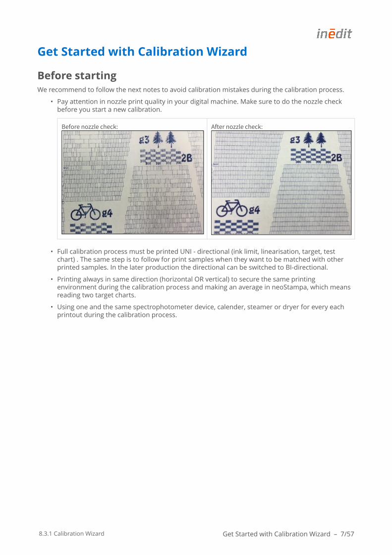
• Pay attention in nozzle print quality in your digital machine. Make sure to do the nozzle check before you start a new calibration.
Before nozzle check: After nozzle check:
• Full calibration process must be printed UNI - directional (ink limit, linearisation, target, test chart) . The same step is to follow for print samples when they want to be matched with other printed samples. In the later production the directional can be switched to BI-directional.
• Printing always in same direction (horizontal OR vertical) to secure the same printing environment during the calibration process and making an average in neoStampa, which means reading two target charts.
• Using one and the same spectrophotometer device, calender, steamer or dryer for every each printout during the calibration process.
8.3.1 Calibration Wizard Get Started with Calibration Wizard – 8/57
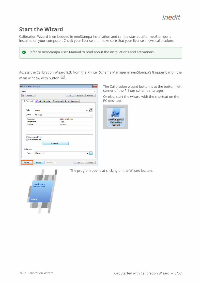
Start the WizardCalibration Wizard is embedded in neoStampa installation and can be started after neoStampa is installed on your computer. Check your license and make sure that your license allows calibrations.
Access the Calibration Wizard 8.3. from the Printer Scheme Manager in neoStampa's 8 upper bar on the
main window with button .
The Calibration wizard button is at the bottom left corner of the Printer scheme manager.
Or else, start the wizard with the shortcut on the PC desktop.
The program opens at clicking on the Wizard button.
Refer to neoStampa User Manual to read about the installations and activations.
8.3.1 Calibration Wizard Calibration Options – 9/57
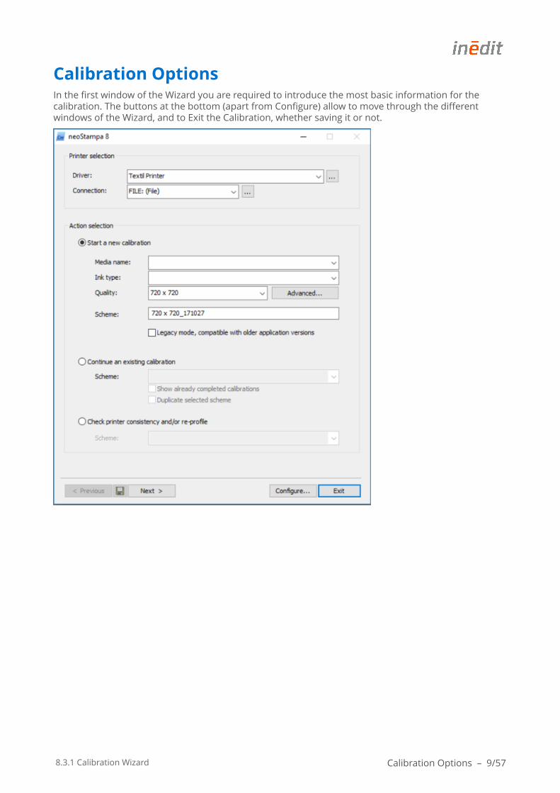
Calibration OptionsIn the first window of the Wizard you are required to introduce the most basic information for the calibration. The buttons at the bottom (apart from Configure) allow to move through the different windows of the Wizard, and to Exit the Calibration, whether saving it or not.
8.3.1 Calibration Wizard Calibration Options – 10/57
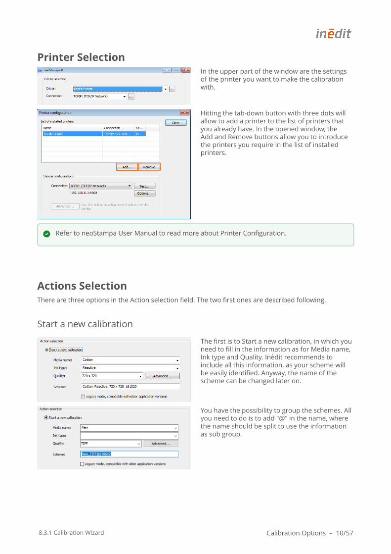
Printer SelectionIn the upper part of the window are the settings of the printer you want to make the calibration with.
Hitting the tab-down button with three dots will allow to add a printer to the list of printers that you already have. In the opened window, the Add and Remove buttons allow you to introduce the printers you require in the list of installed printers.
Actions SelectionThere are three options in the Action selection field. The two first ones are described following.
Start a new calibration
The first is to Start a new calibration, in which you need to fill in the information as for Media name, Ink type and Quality. Inèdit recommends to include all this information, as your scheme will be easily identified. Anyway, the name of the scheme can be changed later on.
You have the possibility to group the schemes. All you need to do is to add "@" in the name, where the name should be split to use the information as sub group.
Refer to neoStampa User Manual to read more about Printer Configuration.
8.3.1 Calibration Wizard Calibration Options – 11/57
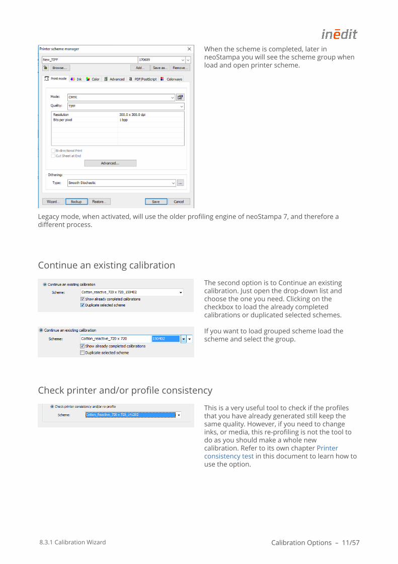
When the scheme is completed, later in neoStampa you will see the scheme group when load and open printer scheme.
Legacy mode, when activated, will use the older profiling engine of neoStampa 7, and therefore a different process.
Continue an existing calibration
The second option is to Continue an existing calibration. Just open the drop-down list and choose the one you need. Clicking on the checkbox to load the already completed calibrations or duplicated selected schemes.
If you want to load grouped scheme load the scheme and select the group.
Check printer and/or profile consistency
This is a very useful tool to check if the profiles that you have already generated still keep the same quality. However, if you need to change inks, or media, this re-profiling is not the tool to do as you should make a whole new calibration. Refer to its own chapter Printer consistency test in this document to learn how to use the option.
8.3.1 Calibration Wizard Calibration Options – 12/57
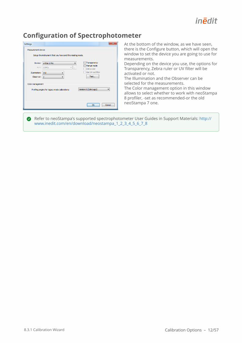
Configuration of SpectrophotometerAt the bottom of the window, as we have seen, there is the Configure button, which will open the window to set the device you are going to use for measurements. Depending on the device you use, the options for Transparency, Zebra ruler or UV filter will be activated or not. The Illumination and the Observer can be selected for the measurements. The Color management option in this window allows to select whether to work with neoStampa 8 profiler, -set as recommended-or the old neoStampa 7 one.
Refer to neoStampa's supported spectrophotometer User Guides in Support Materials: http://www.inedit.com/en/download/neostampa_1_2_3_4_5_6_7_8

8.3.1 Calibration Wizard Print Configurations – 13/57
Print ConfigurationsPrint configuration establishes color specifications such as for Color mode, Print quality and Dithering in the second window of the Wizard.
QualityThe content of this window is driver specific. Quality is usually printer dependent and is provided by the driver specifications of each printer. In the Advanced… button next to it, you can see and change if necessary printer specific parameters, such as single or bi-directional printing, number of passes, etc.
8.3.1 Calibration Wizard Print Configurations – 14/57
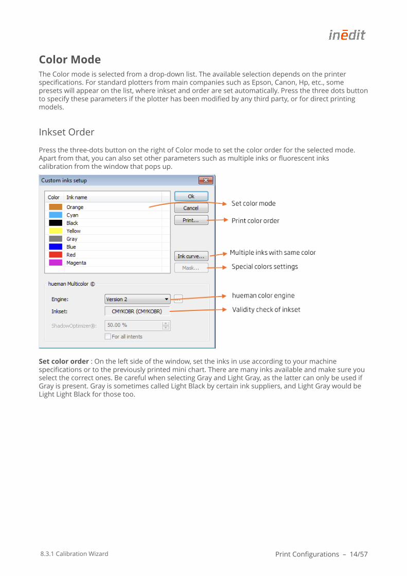
Color ModeThe Color mode is selected from a drop-down list. The available selection depends on the printer specifications. For standard plotters from main companies such as Epson, Canon, Hp, etc., some presets will appear on the list, where inkset and order are set automatically. Press the three dots button to specify these parameters if the plotter has been modified by any third party, or for direct printing models.
Inkset Order
Press the three-dots button on the right of Color mode to set the color order for the selected mode. Apart from that, you can also set other parameters such as multiple inks or fluorescent inks calibration from the window that pops up.
Set color order : On the left side of the window, set the inks in use according to your machine specifications or to the previously printed mini chart. There are many inks available and make sure you select the correct ones. Be careful when selecting Gray and Light Gray, as the latter can only be used if Gray is present. Gray is sometimes called Light Black by certain ink suppliers, and Light Gray would be Light Light Black for those too.
8.3.1 Calibration Wizard Print Configurations – 15/57
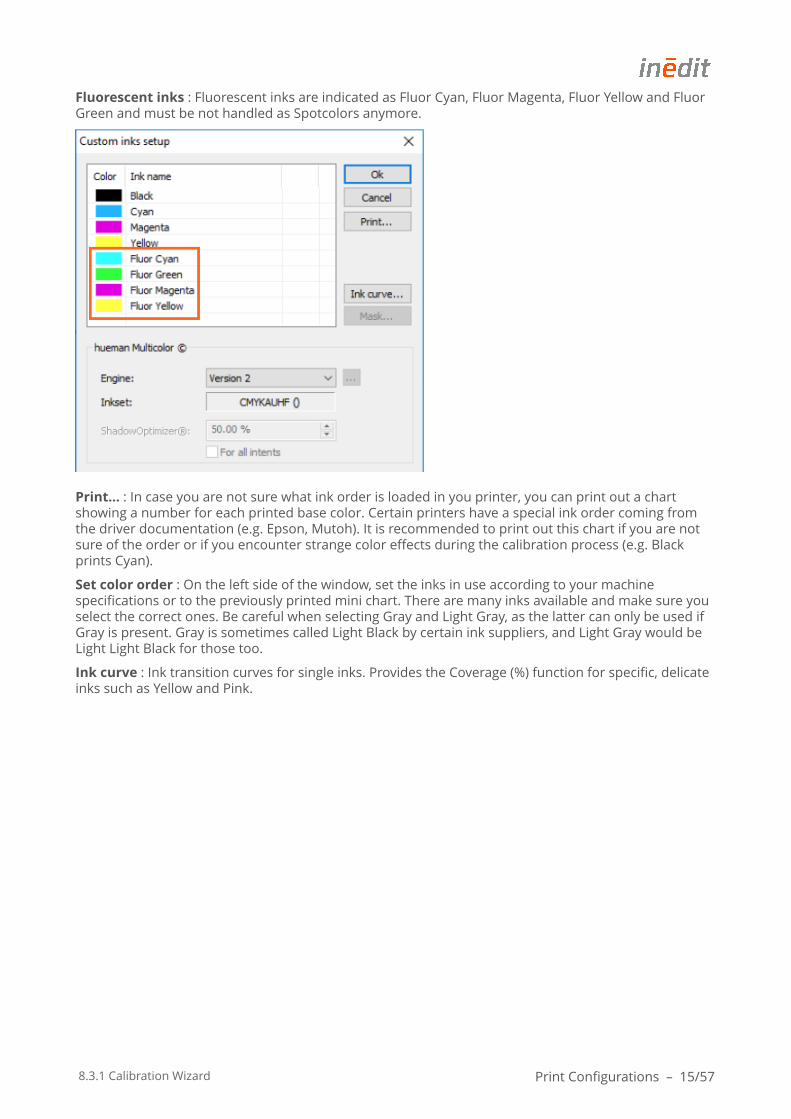
Fluorescent inks : Fluorescent inks are indicated as Fluor Cyan, Fluor Magenta, Fluor Yellow and Fluor Green and must be not handled as Spotcolors anymore.
Print… : In case you are not sure what ink order is loaded in you printer, you can print out a chart showing a number for each printed base color. Certain printers have a special ink order coming from the driver documentation (e.g. Epson, Mutoh). It is recommended to print out this chart if you are not sure of the order or if you encounter strange color effects during the calibration process (e.g. Black prints Cyan).
Set color order : On the left side of the window, set the inks in use according to your machine specifications or to the previously printed mini chart. There are many inks available and make sure you select the correct ones. Be careful when selecting Gray and Light Gray, as the latter can only be used if Gray is present. Gray is sometimes called Light Black by certain ink suppliers, and Light Gray would be Light Light Black for those too.
Ink curve : Ink transition curves for single inks. Provides the Coverage (%) function for specific, delicate inks such as Yellow and Pink.
8.3.1 Calibration Wizard Print Configurations – 16/57
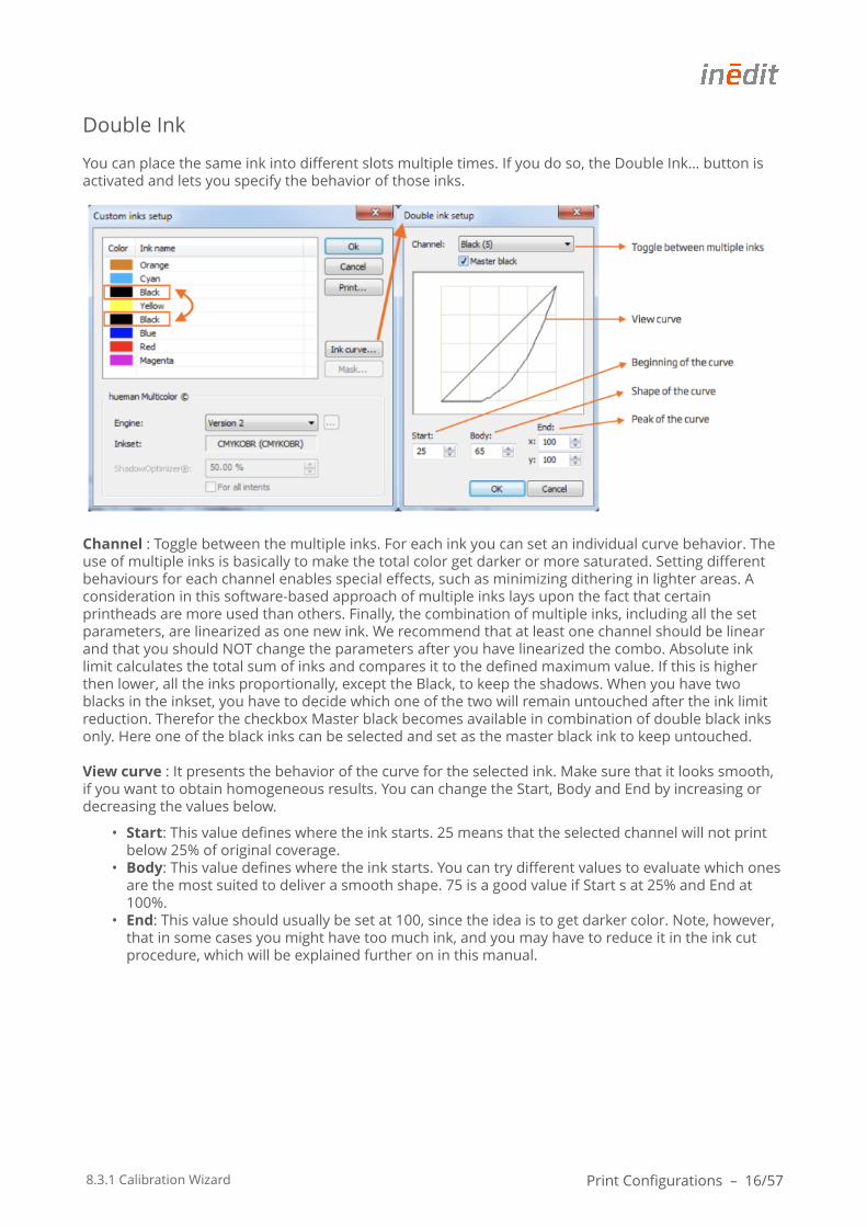
Double Ink
You can place the same ink into different slots multiple times. If you do so, the Double Ink… button is activated and lets you specify the behavior of those inks.
Channel : Toggle between the multiple inks. For each ink you can set an individual curve behavior. The use of multiple inks is basically to make the total color get darker or more saturated. Setting different behaviours for each channel enables special effects, such as minimizing dithering in lighter areas. A consideration in this software-based approach of multiple inks lays upon the fact that certain printheads are more used than others. Finally, the combination of multiple inks, including all the set parameters, are linearized as one new ink. We recommend that at least one channel should be linear and that you should NOT change the parameters after you have linearized the combo. Absolute ink limit calculates the total sum of inks and compares it to the defined maximum value. If this is higher then lower, all the inks proportionally, except the Black, to keep the shadows. When you have two blacks in the inkset, you have to decide which one of the two will remain untouched after the ink limit reduction. Therefor the checkbox Master black becomes available in combination of double black inks only. Here one of the black inks can be selected and set as the master black ink to keep untouched.
View curve : It presents the behavior of the curve for the selected ink. Make sure that it looks smooth, if you want to obtain homogeneous results. You can change the Start, Body and End by increasing or decreasing the values below.
• Start: This value defines where the ink starts. 25 means that the selected channel will not print below 25% of original coverage.
• Body: This value defines where the ink starts. You can try different values to evaluate which ones are the most suited to deliver a smooth shape. 75 is a good value if Start s at 25% and End at 100%.
• End: This value should usually be set at 100, since the idea is to get darker color. Note, however, that in some cases you might have too much ink, and you may have to reduce it in the ink cut procedure, which will be explained further on in this manual.
8.3.1 Calibration Wizard Print Configurations – 17/57
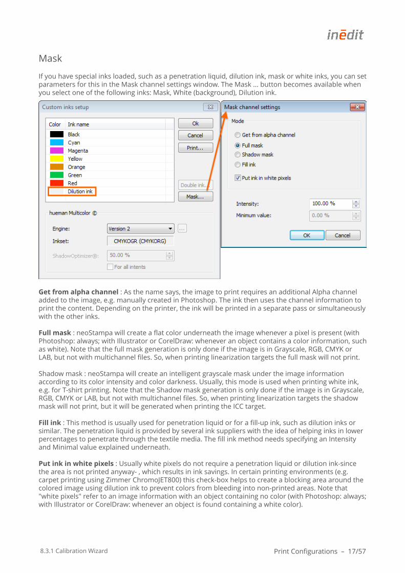
Mask
If you have special inks loaded, such as a penetration liquid, dilution ink, mask or white inks, you can set parameters for this in the Mask channel settings window. The Mask ... button becomes available when you select one of the following inks: Mask, White (background), Dilution ink.
Get from alpha channel : As the name says, the image to print requires an additional Alpha channel added to the image, e.g. manually created in Photoshop. The ink then uses the channel information to print the content. Depending on the printer, the ink will be printed in a separate pass or simultaneously with the other inks.
Full mask : neoStampa will create a flat color underneath the image whenever a pixel is present (with Photoshop: always; with Illustrator or CorelDraw: whenever an object contains a color information, such as white). Note that the full mask generation is only done if the image is in Grayscale, RGB, CMYK or LAB, but not with multichannel files. So, when printing linearization targets the full mask will not print.
Shadow mask : neoStampa will create an intelligent grayscale mask under the image information according to its color intensity and color darkness. Usually, this mode is used when printing white ink, e.g. for T-shirt printing. Note that the Shadow mask generation is only done if the image is in Grayscale, RGB, CMYK or LAB, but not with multichannel files. So, when printing linearization targets the shadow mask will not print, but it will be generated when printing the ICC target.
Fill ink : This method is usually used for penetration liquid or for a fill-up ink, such as dilution inks or similar. The penetration liquid is provided by several ink suppliers with the idea of helping inks in lower percentages to penetrate through the textile media. The fill ink method needs specifying an Intensity and Minimal value explained underneath.
Put ink in white pixels : Usually white pixels do not require a penetration liquid or dilution ink-since the area is not printed anyway- , which results in ink savings. In certain printing environments (e.g. carpet printing using Zimmer ChromoJET800) this check-box helps to create a blocking area around the colored image using dilution ink to prevent colors from bleeding into non-printed areas. Note that "white pixels" refer to an image information with an object containing no color (with Photoshop: always; with Illustrator or CorelDraw: whenever an object is found containing a white color).

8.3.1 Calibration Wizard Print Configurations – 18/57
Intensity : The Fill ink method will fill up with dilution ink, whenever this specified value is not reached by the absolute amount of other inks in the ink set. So, when you print 10% Cyan+25%Magenta+30%Gray, the absolute amount of ink will be 65%. In this case, neoStampa will automatically add a 35% of dilution ink for better penetration.
Minimum value : Specifying a minimum value for the Fill ink method adds a certain amount to an absolute ink amount in any case. Scenario: If you set intensity to 100% and the Minimum value to 10% and the absolute amount of ink of 25% Cyan+35% Magenta+ 75% Gray exceeds the 100% of specified Intensity, then neoStampa will add another 10% on top of it. This will help the ink to penetrate even more, but can also cause a certain amount of bleeding if applied too much. This value should be used with care.
8.3.1 Calibration Wizard Print Configurations – 19/57
DitheringneoStampa 8 provides different raster methods. Two of them are the most common to use: Smooth Stochastic (default) and Diffusion v2.
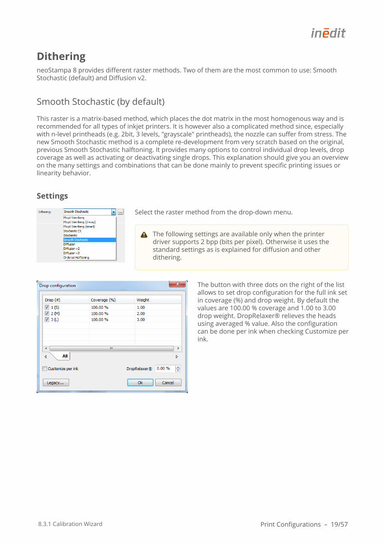
Smooth Stochastic (by default)
This raster is a matrix-based method, which places the dot matrix in the most homogenous way and is recommended for all types of inkjet printers. It is however also a complicated method since, especially with n-level printheads (e.g. 2bit, 3 levels, "grayscale" printheads), the nozzle can suffer from stress. The new Smooth Stochastic method is a complete re-development from very scratch based on the original, previous Smooth Stochastic halftoning. It provides many options to control individual drop levels, drop coverage as well as activating or deactivating single drops. This explanation should give you an overview on the many settings and combinations that can be done mainly to prevent specific printing issues or linearity behavior.
Settings
Select the raster method from the drop-down menu.
The button with three dots on the right of the list allows to set drop configuration for the full ink set in coverage (%) and drop weight. By default the values are 100.00 % coverage and 1.00 to 3.00 drop weight. DropRelaxer® relieves the heads using averaged % value. Also the configuration can be done per ink when checking Customize per ink.
The following settings are available only when the printer driver supports 2 bpp (bits per pixel). Otherwise it uses the standard settings as is explained for diffusion and other dithering.
8.3.1 Calibration Wizard Print Configurations – 20/57
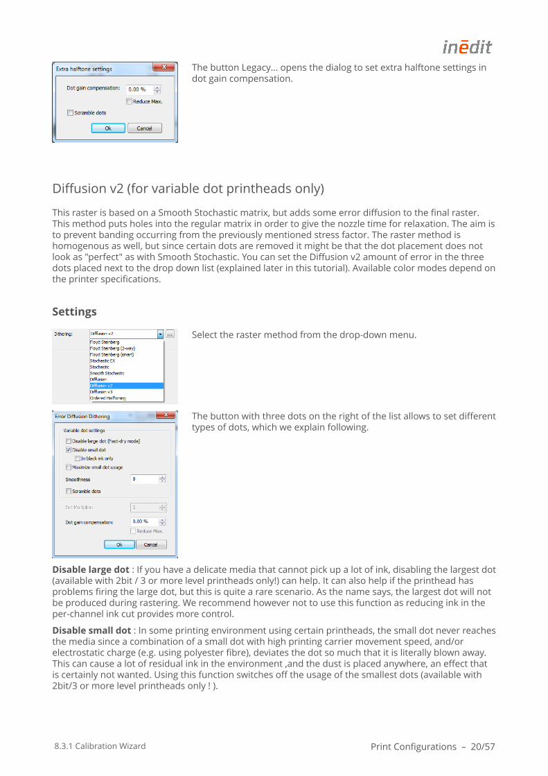
The button Legacy… opens the dialog to set extra halftone settings in dot gain compensation.
Diffusion v2 (for variable dot printheads only)
This raster is based on a Smooth Stochastic matrix, but adds some error diffusion to the final raster. This method puts holes into the regular matrix in order to give the nozzle time for relaxation. The aim is to prevent banding occurring from the previously mentioned stress factor. The raster method is homogenous as well, but since certain dots are removed it might be that the dot placement does not look as "perfect" as with Smooth Stochastic. You can set the Diffusion v2 amount of error in the three dots placed next to the drop down list (explained later in this tutorial). Available color modes depend on the printer specifications.
Settings
Select the raster method from the drop-down menu.
The button with three dots on the right of the list allows to set different types of dots, which we explain following.
Disable large dot : If you have a delicate media that cannot pick up a lot of ink, disabling the largest dot (available with 2bit / 3 or more level printheads only!) can help. It can also help if the printhead has problems firing the large dot, but this is quite a rare scenario. As the name says, the largest dot will not be produced during rastering. We recommend however not to use this function as reducing ink in the per-channel ink cut provides more control.
Disable small dot : In some printing environment using certain printheads, the small dot never reaches the media since a combination of a small dot with high printing carrier movement speed, and/or electrostatic charge (e.g. using polyester fibre), deviates the dot so much that it is literally blown away. This can cause a lot of residual ink in the environment ,and the dust is placed anywhere, an effect that is certainly not wanted. Using this function switches off the usage of the smallest dots (available with 2bit/3 or more level printheads only ! ).
8.3.1 Calibration Wizard Print Configurations – 21/57
Only for black ink : If this box is selected in combination with "Disable small dot", then the smallest dot is only omitted in the Black channel(s).
Smoothness : This value becomes available when working with Diffusion v2 raster method in combination with an n-Bit / n-Level printhead. The smoothness defines the amount of error introduced to the matrix raster to avoid stress from the nozzles when firing full-time (mentioned in Dithering Part 1). A smoothness of 10 means that Diffusion v2 does not have any error diffusion (=Smooth Stochastic). By decreasing this value, dots are removed from the regular matrix and the n-Levels of variable drop technology are diffused into each other. A value of 6-9 delivers a good balance between quality and stress-reduction to printheads with variable dot technology. If you go lower than this value, there can be too much noise in the result and the print-out will go grainy. We recommend a value of 7 if you encounter such a firing stress problem. Note that changing to Diffusion v2 or changing the amount of Smoothness requires re-linearizing the printing conditions.
Dot multiplier : This value must be left at "1". Note: We recommend NOT to change it.
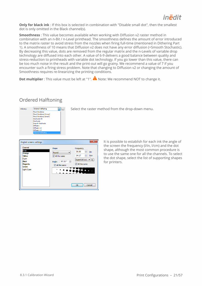
Ordered Halftoning
Select the raster method from the drop-down menu.
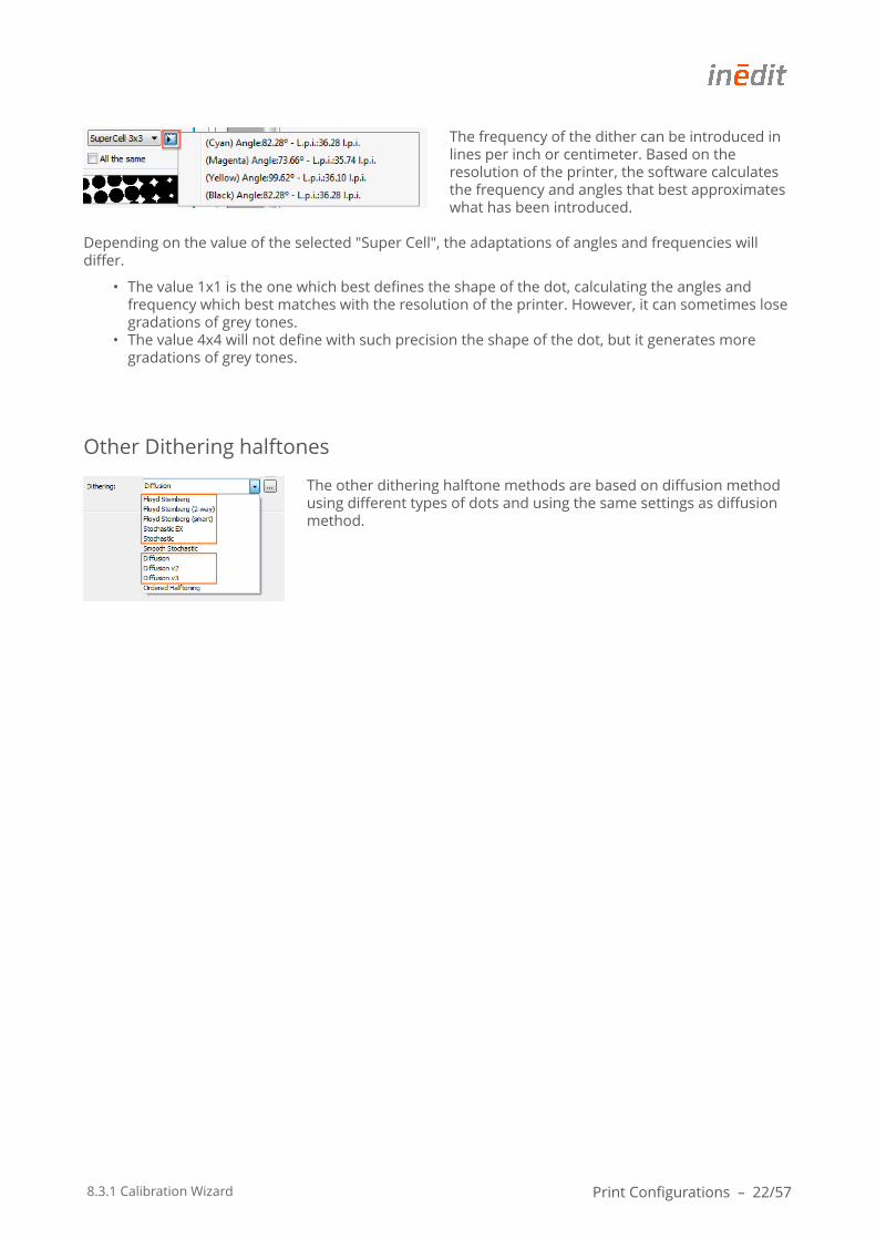
It is possible to establish for each ink the angle of the screen the frequency (l/in, l/cm) and the dot shape, although the most common procedure is to use the same one for all the channels. To select the dot shape, select the list of supporting shapes for printers.
8.3.1 Calibration Wizard Print Configurations – 22/57
The frequency of the dither can be introduced in lines per inch or centimeter. Based on the resolution of the printer, the software calculates the frequency and angles that best approximates what has been introduced.
Depending on the value of the selected "Super Cell", the adaptations of angles and frequencies will differ.
• The value 1x1 is the one which best defines the shape of the dot, calculating the angles and frequency which best matches with the resolution of the printer. However, it can sometimes lose gradations of grey tones.
• The value 4x4 will not define with such precision the shape of the dot, but it generates more gradations of grey tones.
Other Dithering halftones
The other dithering halftone methods are based on diffusion method using different types of dots and using the same settings as diffusion method.
8.3.1 Calibration Wizard Ink Limit and Linearization – 23/57
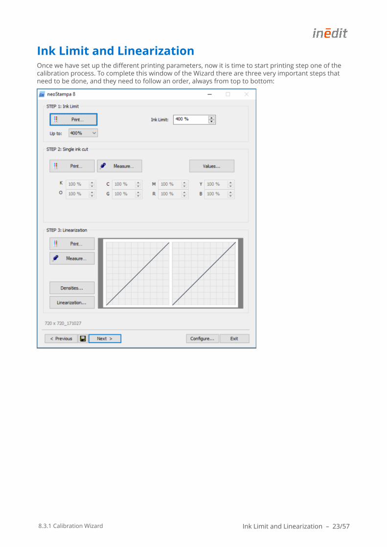
Ink Limit and LinearizationOnce we have set up the different printing parameters, now it is time to start printing step one of the calibration process. To complete this window of the Wizard there are three very important steps that need to be done, and they need to follow an order, always from top to bottom:
8.3.1 Calibration Wizard Ink Limit and Linearization – 24/57
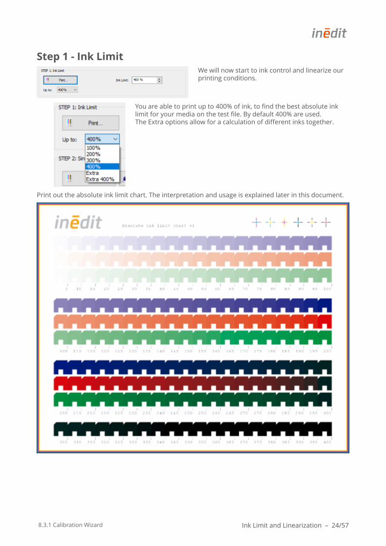
Step 1 - Ink LimitWe will now start to ink control and linearize our printing conditions.
You are able to print up to 400% of ink, to find the best absolute ink limit for your media on the test file. By default 400% are used. The Extra options allow for a calculation of different inks together.
Print out the absolute ink limit chart. The interpretation and usage is explained later in this document.
8.3.1 Calibration Wizard Ink Limit and Linearization – 25/57
Print configuration - Ink Limit
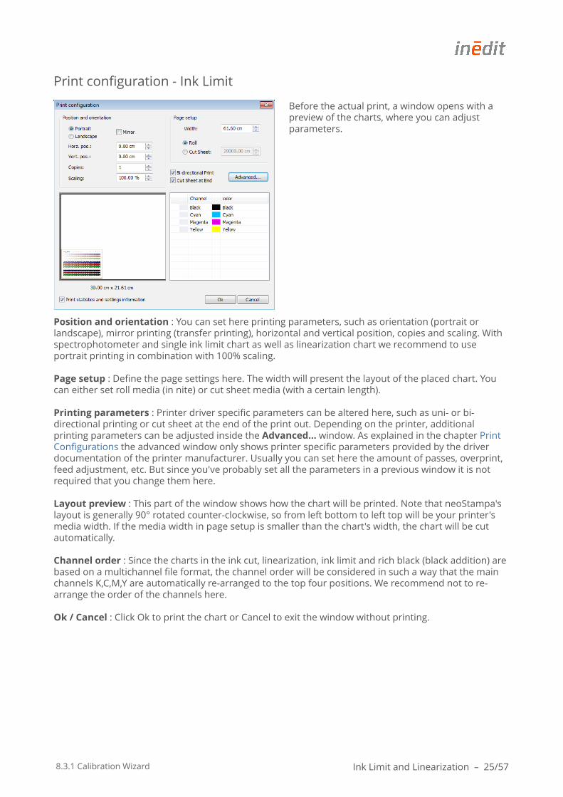
Before the actual print, a window opens with a preview of the charts, where you can adjust parameters.
Position and orientation : You can set here printing parameters, such as orientation (portrait or landscape), mirror printing (transfer printing), horizontal and vertical position, copies and scaling. With spectrophotometer and single ink limit chart as well as linearization chart we recommend to use portrait printing in combination with 100% scaling.
Page setup : Define the page settings here. The width will present the layout of the placed chart. You can either set roll media (in nite) or cut sheet media (with a certain length).
Printing parameters : Printer driver specific parameters can be altered here, such as uni- or bi-directional printing or cut sheet at the end of the print out. Depending on the printer, additional printing parameters can be adjusted inside the Advanced… window. As explained in the chapter Print Configurations the advanced window only shows printer specific parameters provided by the driver documentation of the printer manufacturer. Usually you can set here the amount of passes, overprint, feed adjustment, etc. But since you've probably set all the parameters in a previous window it is not required that you change them here.
Layout preview : This part of the window shows how the chart will be printed. Note that neoStampa's layout is generally 90° rotated counter-clockwise, so from left bottom to left top will be your printer's media width. If the media width in page setup is smaller than the chart's width, the chart will be cut automatically.
Channel order : Since the charts in the ink cut, linearization, ink limit and rich black (black addition) are based on a multichannel file format, the channel order will be considered in such a way that the main channels K,C,M,Y are automatically re-arranged to the top four positions. We recommend not to re-arrange the order of the channels here.
Ok / Cancel : Click Ok to print the chart or Cancel to exit the window without printing.
8.3.1 Calibration Wizard Ink Limit and Linearization – 26/57
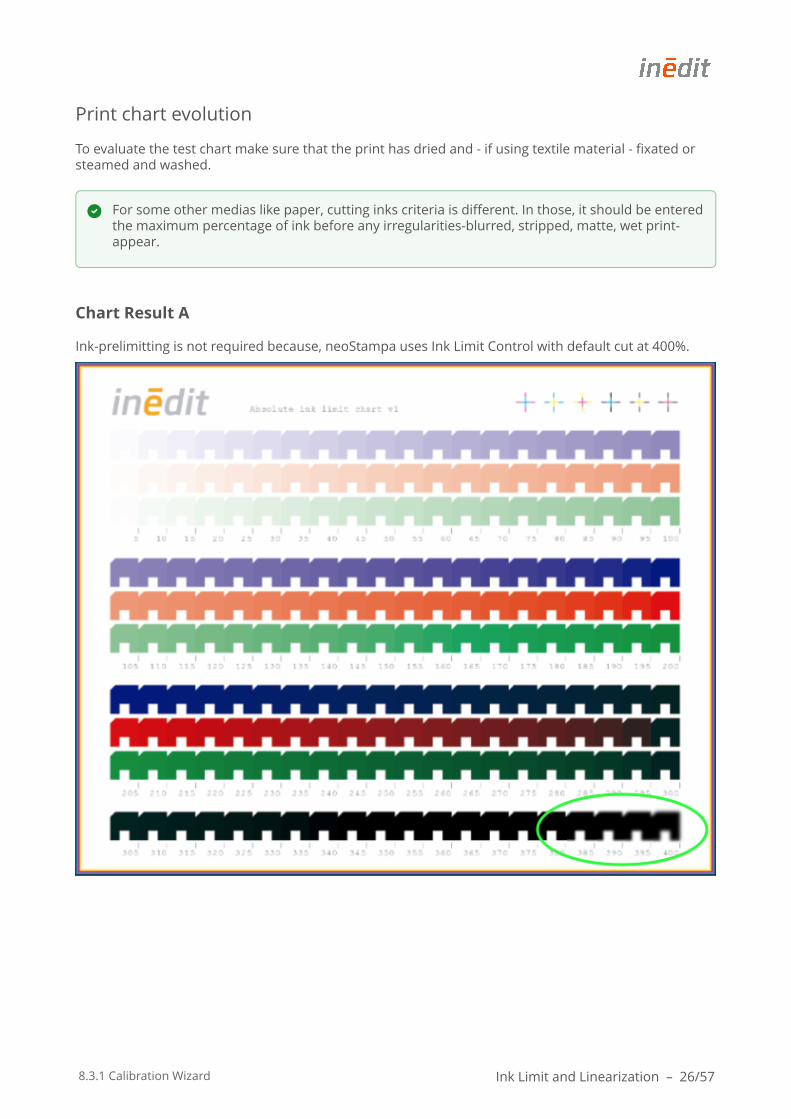
Print chart evolution
To evaluate the test chart make sure that the print has dried and - if using textile material - fixated or steamed and washed.
Chart Result A
Ink-prelimitting is not required because, neoStampa uses Ink Limit Control with default cut at 400%.
For some other medias like paper, cutting inks criteria is different. In those, it should be entered the maximum percentage of ink before any irregularities-blurred, stripped, matte, wet print-appear.
8.3.1 Calibration Wizard Ink Limit and Linearization – 27/57
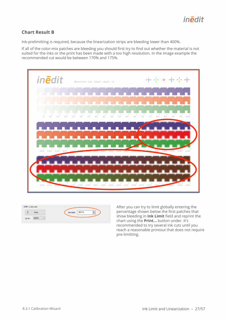
Chart Result B
Ink-prelimitting is required, because the linearization strips are bleeding lower than 400%.
If all of the color-mix patches are bleeding you should first try to find out whether the material is not suited for the inks or the print has been made with a too high resolution. In the image example the recommended cut would be between 170% and 175%.
After you can try to limit globally entering the percentage shown below the first patches that show bleeding in Ink Limit field and reprint the chart using the Print... button under. It's recommended to try several ink cuts until you reach a reasonable printout that does not require pre-limitting.
8.3.1 Calibration Wizard Ink Limit and Linearization – 28/57
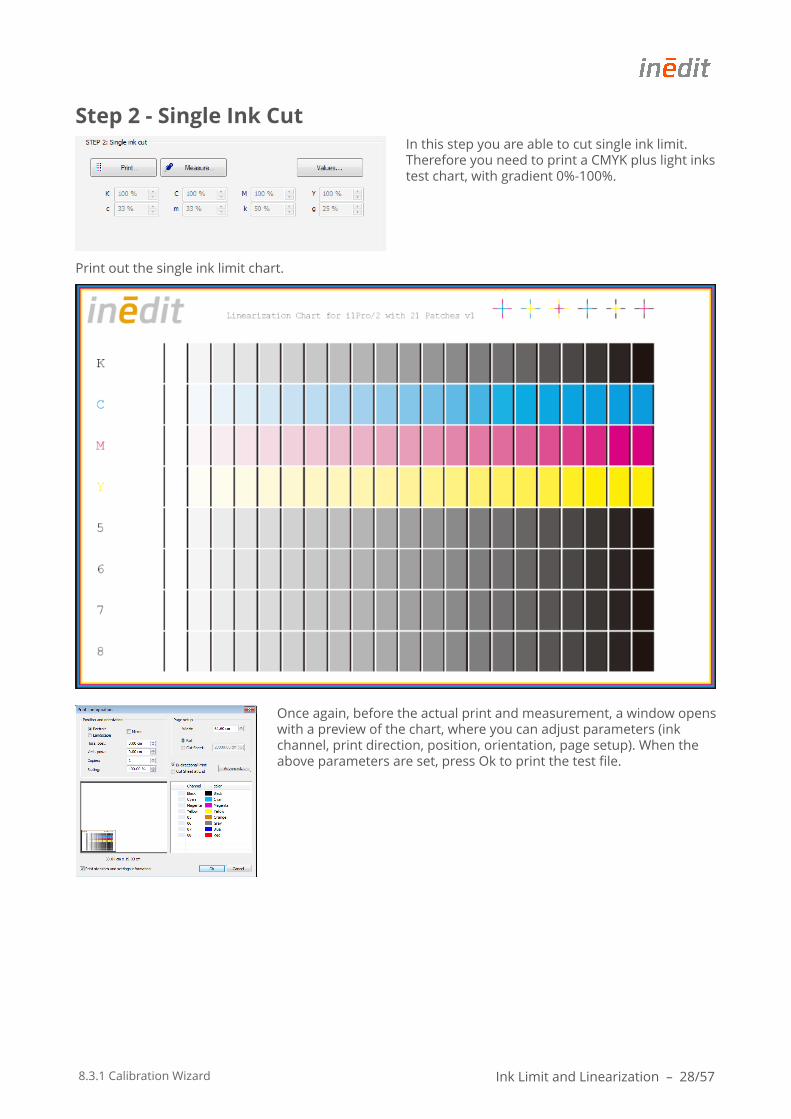
Step 2 - Single Ink CutIn this step you are able to cut single ink limit. Therefore you need to print a CMYK plus light inks test chart, with gradient 0%-100%.
Print out the single ink limit chart.
Once again, before the actual print and measurement, a window opens with a preview of the chart, where you can adjust parameters (ink channel, print direction, position, orientation, page setup). When the above parameters are set, press Ok to print the test file.
8.3.1 Calibration Wizard Ink Limit and Linearization – 29/57
Measurement - Single Ink Cut
Once the print is ready washed and dried or vaporized proceed with the Measurement. Press the 'Measure...' button and connect the spectrophotometer.
Then start reading the lines carefully and slowly according to given specifications.
Calibration Wizard offers the possibility to get 3 measurements for each print. This is useful when for example the media is rough, and we want to get much precise results. The Wizard will produce average values from the 3 measurements using the methods that are explained in the printer profiling step.
Notice also that the data for this measurements and of each reading can be exported with Export…, if necessary, they can also be imported with Import… button.
Pressing right-click mouse opens the spectrum visor showing the spectral curve of the selected chart patch compared to same chart patch in all measurements.
8.3.1 Calibration Wizard Ink Limit and Linearization – 30/57
Measurement evaluation
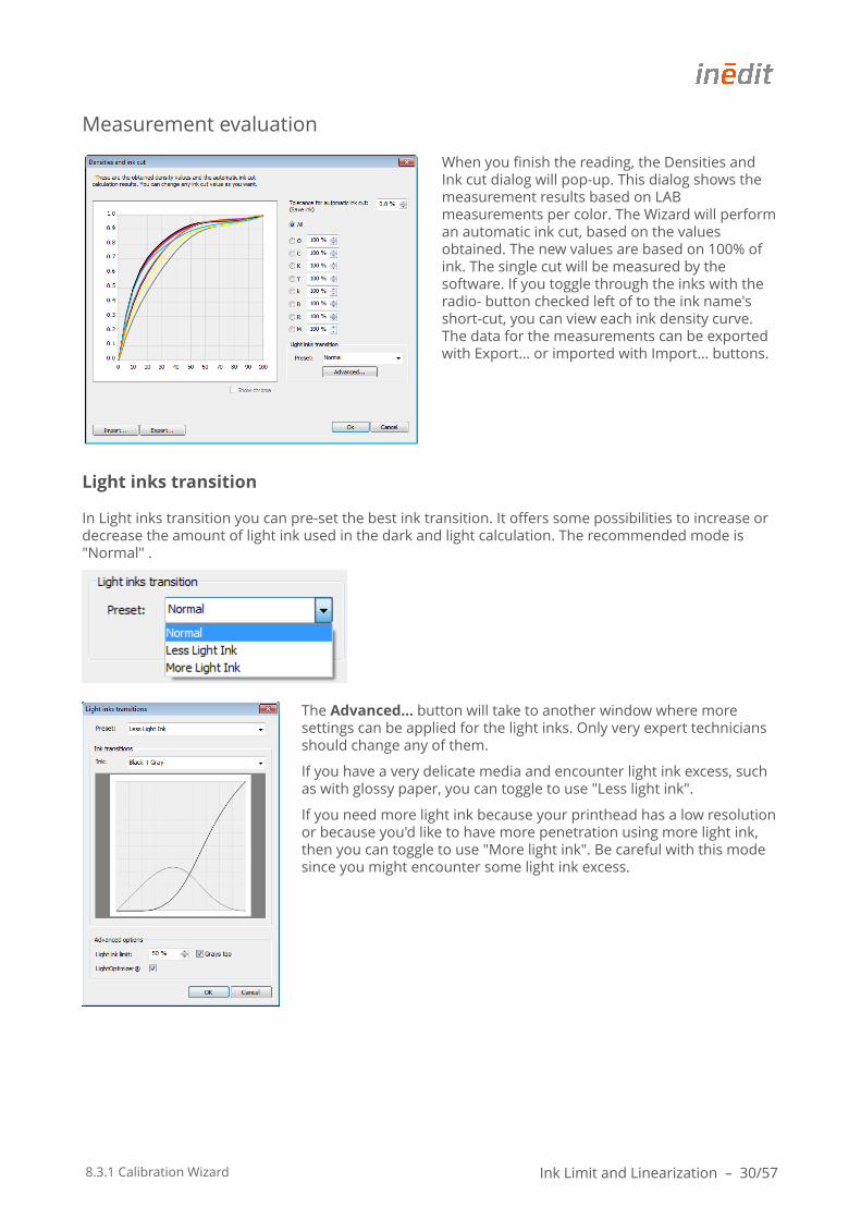
When you finish the reading, the Densities and Ink cut dialog will pop-up. This dialog shows the measurement results based on LAB measurements per color. The Wizard will perform an automatic ink cut, based on the values obtained. The new values are based on 100% of ink. The single cut will be measured by the software. If you toggle through the inks with the radio- button checked left of to the ink name's short-cut, you can view each ink density curve. The data for the measurements can be exported with Export… or imported with Import… buttons.
Light inks transition
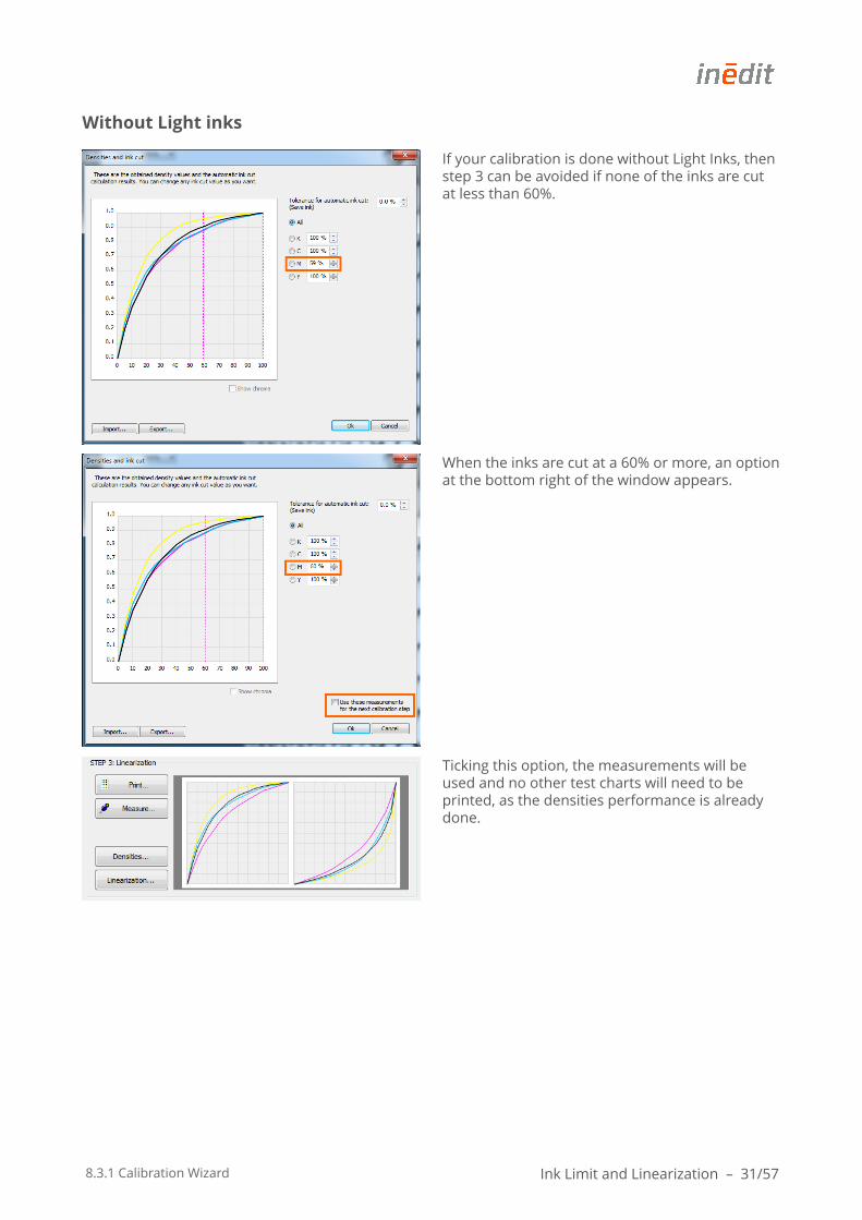
In Light inks transition you can pre-set the best ink transition. It offers some possibilities to increase or decrease the amount of light ink used in the dark and light calculation. The recommended mode is "Normal" .
The Advanced… button will take to another window where more settings can be applied for the light inks. Only very expert technicians should change any of them.
If you have a very delicate media and encounter light ink excess, such as with glossy paper, you can toggle to use "Less light ink".
If you need more light ink because your printhead has a low resolution or because you'd like to have more penetration using more light ink, then you can toggle to use "More light ink". Be careful with this mode since you might encounter some light ink excess.
8.3.1 Calibration Wizard Ink Limit and Linearization – 31/57
Without Light inks
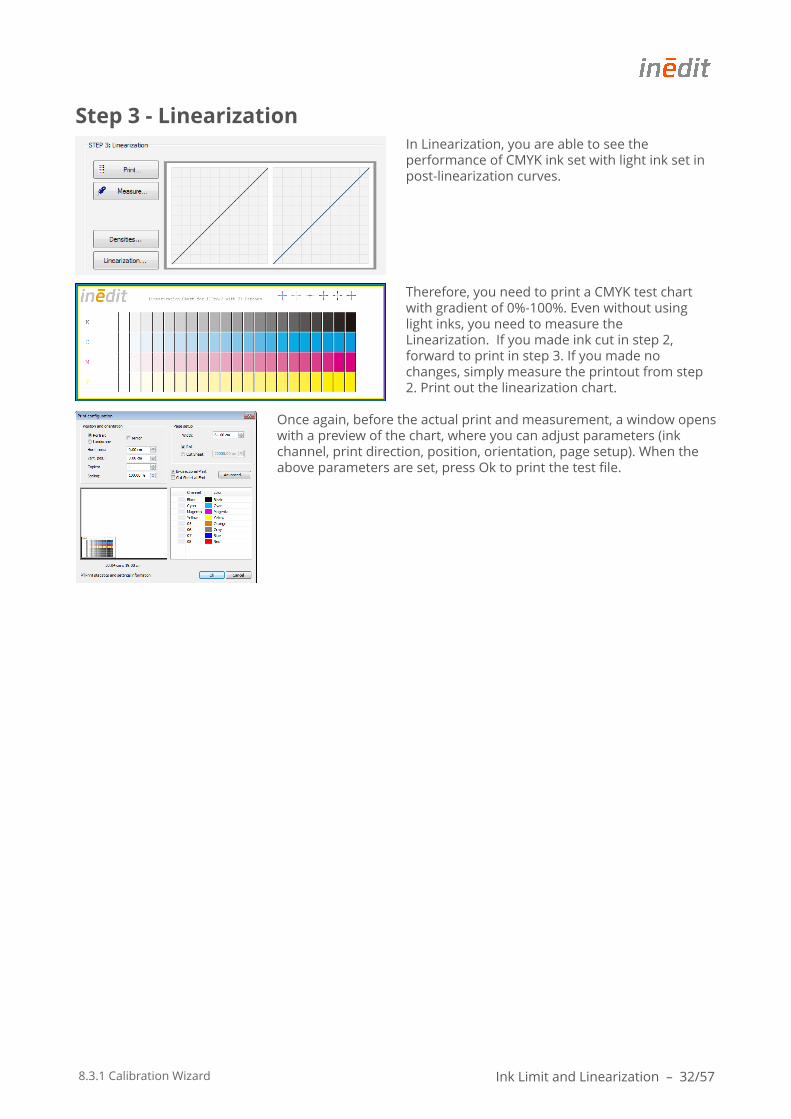
If your calibration is done without Light Inks, then step 3 can be avoided if none of the inks are cut at less than 60%.
When the inks are cut at a 60% or more, an option at the bottom right of the window appears.
Ticking this option, the measurements will be used and no other test charts will need to be printed, as the densities performance is already done.
8.3.1 Calibration Wizard Ink Limit and Linearization – 32/57
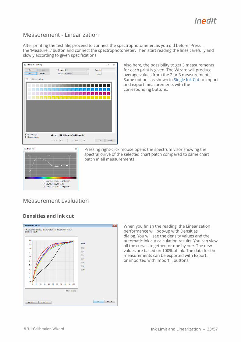
Step 3 - LinearizationIn Linearization, you are able to see the performance of CMYK ink set with light ink set in post-linearization curves.
Therefore, you need to print a CMYK test chart with gradient of 0%-100%. Even without using light inks, you need to measure the Linearization. If you made ink cut in step 2, forward to print in step 3. If you made no changes, simply measure the printout from step 2. Print out the linearization chart.
Once again, before the actual print and measurement, a window opens with a preview of the chart, where you can adjust parameters (ink channel, print direction, position, orientation, page setup). When the above parameters are set, press Ok to print the test file.
8.3.1 Calibration Wizard Ink Limit and Linearization – 33/57
Measurement - Linearization
After printing the test file, proceed to connect the spectrophotometer, as you did before. Press the 'Measure...' button and connect the spectrophotometer. Then start reading the lines carefully and slowly according to given specifications.
Also here, the possibility to get 3 measurements for each print is given. The Wizard will produce average values from the 2 or 3 measurements. Same options as shown in Single Ink Cut to import and export measurements with the corresponding buttons.
Pressing right-click mouse opens the spectrum visor showing the spectral curve of the selected chart patch compared to same chart patch in all measurements.
Measurement evaluation
Densities and ink cut
When you finish the reading, the Linearization performance will pop-up with Densities dialog. You will see the density values and the automatic ink cut calculation results. You can view all the curves together, or one by one. The new values are based on 100% of ink. The data for the measurements can be exported with Export… or imported with Import… buttons.
8.3.1 Calibration Wizard Ink Limit and Linearization – 34/57
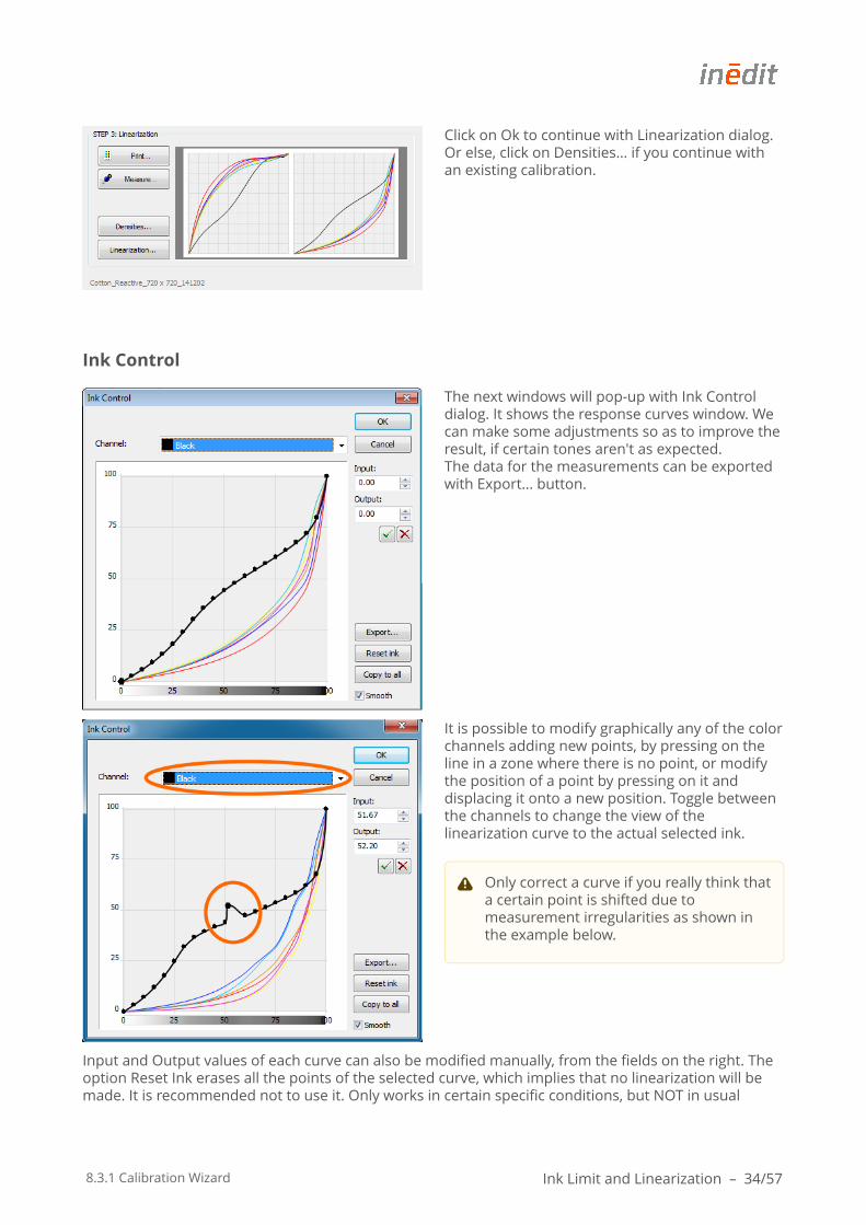
Click on Ok to continue with Linearization dialog. Or else, click on Densities… if you continue with an existing calibration.
Ink Control
The next windows will pop-up with Ink Control dialog. It shows the response curves window. We can make some adjustments so as to improve the result, if certain tones aren't as expected. The data for the measurements can be exported with Export… button.
It is possible to modify graphically any of the color channels adding new points, by pressing on the line in a zone where there is no point, or modify the position of a point by pressing on it and displacing it onto a new position. Toggle between the channels to change the view of the linearization curve to the actual selected ink.
Input and Output values of each curve can also be modified manually, from the fields on the right. The option Reset Ink erases all the points of the selected curve, which implies that no linearization will be made. It is recommended not to use it. Only works in certain specific conditions, but NOT in usual
Only correct a curve if you really think that a certain point is shifted due to measurement irregularities as shown in the example below.
8.3.1 Calibration Wizard Ink Limit and Linearization – 35/57
cases. The button Copy to all allows copying the reference points of a curve to all the other ones. In case few points are entered, the option Smooth can be selected so that the resulting curve is smooth and doesn't have rough changes in tonality adjustments. This function enables a 16bit interpolation between the dots, which make a gradient much smoother. We recommend to always leave this button on.
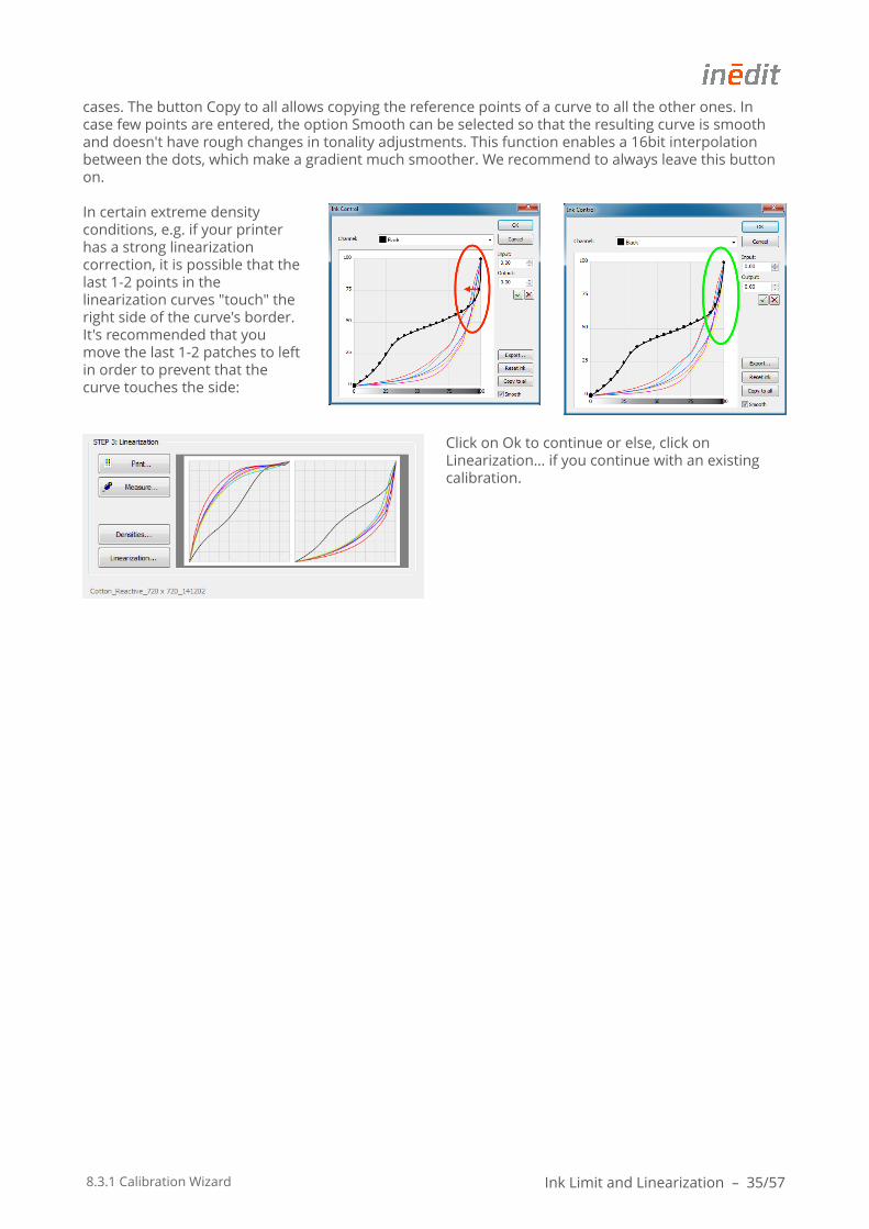
In certain extreme density conditions, e.g. if your printer has a strong linearization correction, it is possible that the last 1-2 points in the linearization curves "touch" the right side of the curve's border. It's recommended that you move the last 1-2 patches to left in order to prevent that the curve touches the side:
Click on Ok to continue or else, click on Linearization… if you continue with an existing calibration.
8.3.1 Calibration Wizard hueman V2 - Black Generation – 36/57
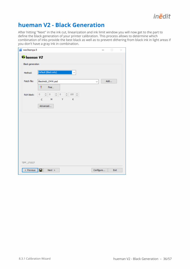
hueman V2 - Black GenerationAfter hitting "Next" in the ink cut, linearization and ink limit window you will now get to the part to define the black generation of your printer calibration. This process allows to determine which combination of inks provide the best black as well as to prevent dithering from black ink in light areas if you don't have a gray ink in combination.
8.3.1 Calibration Wizard hueman V2 - Black Generation – 37/57
Method
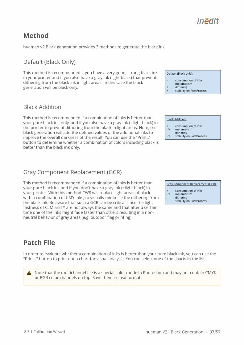
hueman v2 Black generation provides 3 methods to generate the black ink:
Default (Black Only)
This method is recommended if you have a very good, strong black ink in your printer and if you also have a gray ink (light black) that prevents dithering from the black ink in light areas. In this case the black generation will be black only.
Black Addition
This method is recommended if a combination of inks is better than your pure black ink only, and if you also have a gray ink (=light black) in the printer to prevent dithering from the black in light areas. Here, the black generation will add the defined values of the additional inks to improve the overall darkness of the result. You can use the "Print.." button to determine whether a combination of colors including black is better than the black ink only.
Gray Component Replacement (GCR)
This method is recommended if a combination of inks is better than your pure black ink and if you don't have a gray ink (=light black) in your printer. With this method CW8 will replace light areas of black with a combination of CMY inks, to visually minimize the dithering from the black ink. Be aware that such a GCR can be critical since the light fastness of C, M and Y are not always the same and that after a certain time one of the inks might fade faster than others resulting in a non-neutral behavior of gray areas (e.g. outdoor flag printing).
Patch File
In order to evaluate whether a combination of inks is better than your pure black ink, you can use the "Print.." button to print out a chart for visual analysis. You can select one of the charts in the list.
Note that the multichannel file is a special color mode in Photoshop and may not contain CMYK or RGB color channels on top. Save them in .psd format.
8.3.1 Calibration Wizard hueman V2 - Black Generation – 38/57
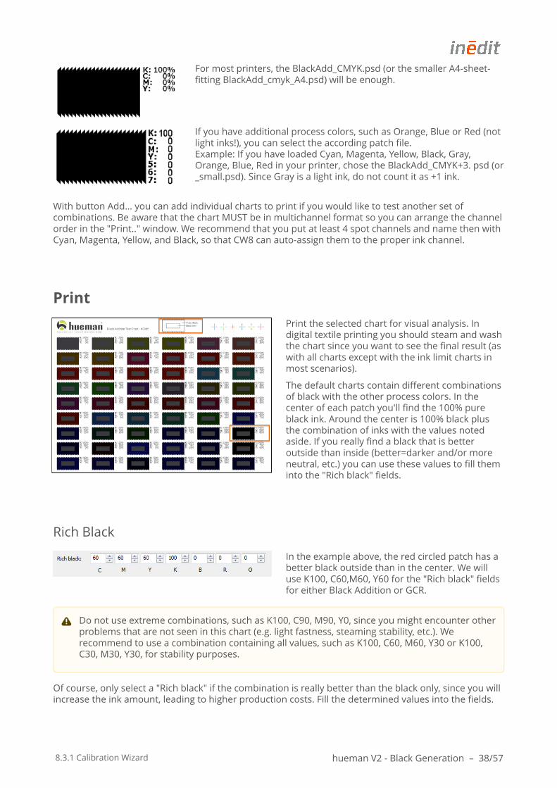
For most printers, the BlackAdd_CMYK.psd (or the smaller A4-sheet-fitting BlackAdd_cmyk_A4.psd) will be enough.
If you have additional process colors, such as Orange, Blue or Red (not light inks!), you can select the according patch file. Example: If you have loaded Cyan, Magenta, Yellow, Black, Gray, Orange, Blue, Red in your printer, chose the BlackAdd_CMYK+3. psd (or _small.psd). Since Gray is a light ink, do not count it as +1 ink.
With button Add… you can add individual charts to print if you would like to test another set of combinations. Be aware that the chart MUST be in multichannel format so you can arrange the channel order in the "Print.." window. We recommend that you put at least 4 spot channels and name then with Cyan, Magenta, Yellow, and Black, so that CW8 can auto-assign them to the proper ink channel.
Print the selected chart for visual analysis. In digital textile printing you should steam and wash the chart since you want to see the final result (as with all charts except with the ink limit charts in most scenarios).
The default charts contain different combinations of black with the other process colors. In the center of each patch you'll find the 100% pure black ink. Around the center is 100% black plus the combination of inks with the values noted aside. If you really find a black that is better outside than inside (better=darker and/or more neutral, etc.) you can use these values to fill them into the "Rich black" fields.
Rich Black
In the example above, the red circled patch has a better black outside than in the center. We will use K100, C60,M60, Y60 for the "Rich black" fields for either Black Addition or GCR.
Of course, only select a "Rich black" if the combination is really better than the black only, since you will increase the ink amount, leading to higher production costs. Fill the determined values into the fields.
Do not use extreme combinations, such as K100, C90, M90, Y0, since you might encounter other problems that are not seen in this chart (e.g. light fastness, steaming stability, etc.). We recommend to use a combination containing all values, such as K100, C60, M60, Y30 or K100, C30, M30, Y30, for stability purposes.
8.3.1 Calibration Wizard hueman V2 - Black Generation – 39/57
You can only use "Rich black" in combination with Black Addition or Gray Component Replacement method.
Advanced
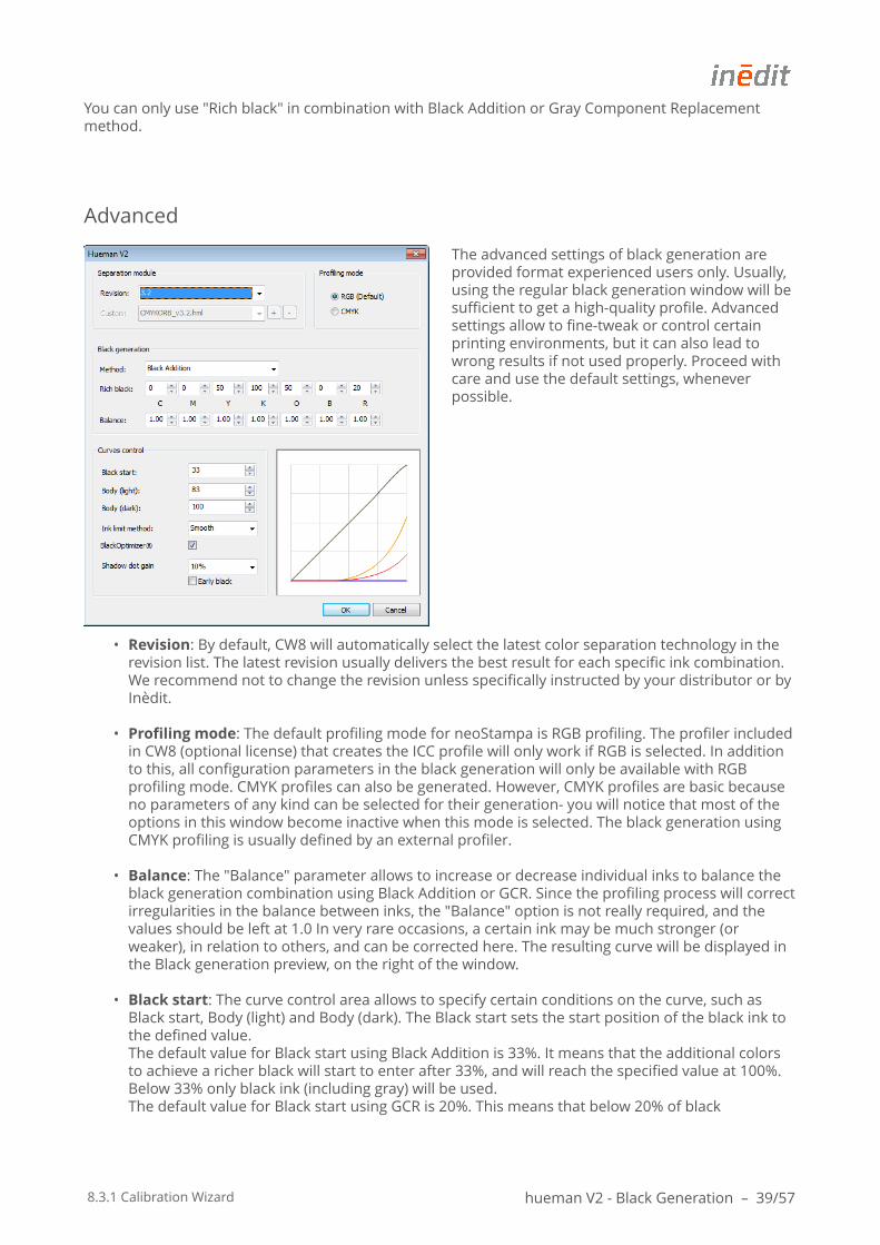
The advanced settings of black generation are provided format experienced users only. Usually, using the regular black generation window will be sufficient to get a high-quality profile. Advanced settings allow to fine-tweak or control certain printing environments, but it can also lead to wrong results if not used properly. Proceed with care and use the default settings, whenever possible.
• Revision: By default, CW8 will automatically select the latest color separation technology in the revision list. The latest revision usually delivers the best result for each specific ink combination. We recommend not to change the revision unless specifically instructed by your distributor or by Inèdit.
• Profiling mode: The default profiling mode for neoStampa is RGB profiling. The profiler included in CW8 (optional license) that creates the ICC profile will only work if RGB is selected. In addition to this, all configuration parameters in the black generation will only be available with RGB profiling mode. CMYK profiles can also be generated. However, CMYK profiles are basic because no parameters of any kind can be selected for their generation- you will notice that most of the options in this window become inactive when this mode is selected. The black generation using CMYK profiling is usually defined by an external profiler.
• Balance: The "Balance" parameter allows to increase or decrease individual inks to balance the black generation combination using Black Addition or GCR. Since the profiling process will correct irregularities in the balance between inks, the "Balance" option is not really required, and the values should be left at 1.0 In very rare occasions, a certain ink may be much stronger (or weaker), in relation to others, and can be corrected here. The resulting curve will be displayed in the Black generation preview, on the right of the window.
• Black start: The curve control area allows to specify certain conditions on the curve, such as Black start, Body (light) and Body (dark). The Black start sets the start position of the black ink to the defined value.The default value for Black start using Black Addition is 33%. It means that the additional colors to achieve a richer black will start to enter after 33%, and will reach the specified value at 100%. Below 33% only black ink (including gray) will be used.The default value for Black start using GCR is 20%. This means that below 20% of black
8.3.1 Calibration Wizard hueman V2 - Black Generation – 40/57
generation, no black ink will be present, but instead it will be replaced with a combination of C, M, and Y inks. This is to prevent dithering of the black ink if no gray ink (=light black inks) is present in the ink set.
• Body (light): The Body light parameter shapes the curve in the lower area of black generation. The ideal value is experimental, but should result in a smooth and regular total curve shape, which can be seen in the Black generation preview. The default value for Body light using Black Addition is 83. The default value fro Body light using GCR is 33.
• Body (dark): The Body dark parameter shapes the curve in the upper area of black generation. Also here, the ideal value is experimental and should result in a totally smooth behavior of the final curve as seen in the Black generation preview. The default value for Body dark using Black Addition is 100. The default value for Body (dark) using GCR is 66.
• Ink limit method. neoStampa includes two methods for ink limiting:Smooth: The default method provides an intelligent ink limiting without clipping behavior in heavy ink load areas. It optimizes the ink amount in extreme areas to provide smoother behavior of gradients but sacrifices 2-3% of gamut.Clip: The clip method just cuts down the exceeding ink to the defined value. Although the gamut might be 2-3% larger in these extreme areas, it is possible that gradients in very dark areas are not as smooth as with the above method.
• BlackOptimizer ®: This function improves the gamut behavior in colorful areas when moving towards saturated, dark colors. Since specially in digital textile printing, the regular GCR method doesn't always directly make a color darker, but turns it duller and sometimes even lighter, an intelligent analysis of color-to-dark is required, to improve the combination of colors in the black generation. BlackOptimizer does this analysis based on whether a color is already dark, and therefore uses less GCR to get darker. It is recommended to leave this button always on. If you encounter some dithering from color-to-dark (e.g. if the black ink starts too early), it might help to switch the function off, although it might make the printer gamut less linear.
• Shadow dot gain: A dot gain can be added to improve overprinting of colors, also in darker areas. An insufficient saturation in dark areas is sometimes caused by an intermediate ink limit behavior, which causes a bump between absolute ink limit (2-mix-colors) and the relative ink limit set in the RIP (e.g. 240%). A regular dot gain is usually applied to all colors, but from the CIELab point of view, the linearity is not given anymore. The Shadow dot gain parameter adds a dot gain only where is it required; in already saturated colors, to counteract the bump effect. The default value of 15% is a good balance between improving the bump effect and laying down too much ink, but mainly depends on how heavy the colors have been linearized.The Early black improves the gradient and linearity from dark-saturated to dark-unsaturated color, affecting the black ink directly in normal cases, and should be switched on by default. Switch it off only if you experience strong jumps in dark-unsaturated areas from the black ink or a rich black combination.
8.3.1 Calibration Wizard Printer Profiling – 41/57
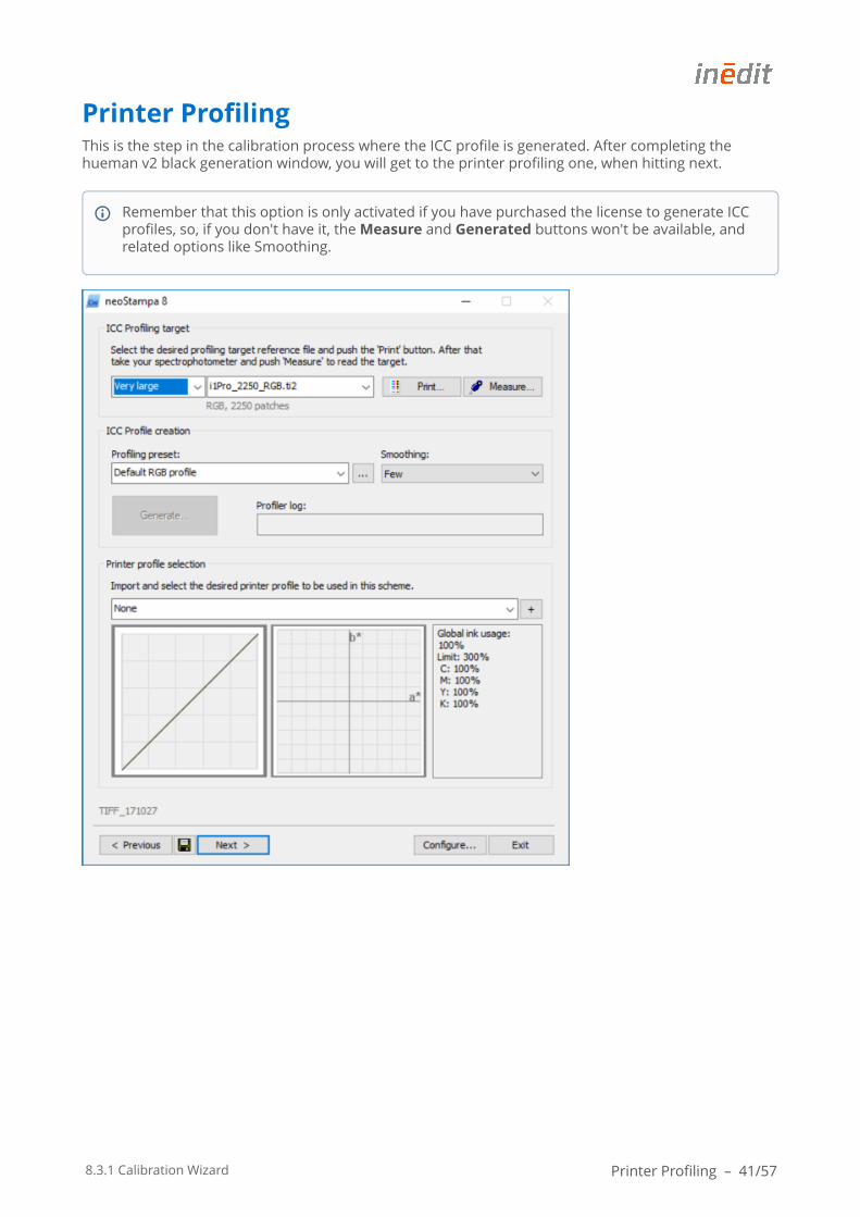
Printer ProfilingThis is the step in the calibration process where the ICC profile is generated. After completing the hueman v2 black generation window, you will get to the printer profiling one, when hitting next.
Remember that this option is only activated if you have purchased the license to generate ICC profiles, so, if you don't have it, the Measure and Generated buttons won't be available, and related options like Smoothing.
8.3.1 Calibration Wizard Printer Profiling – 42/57
Target File
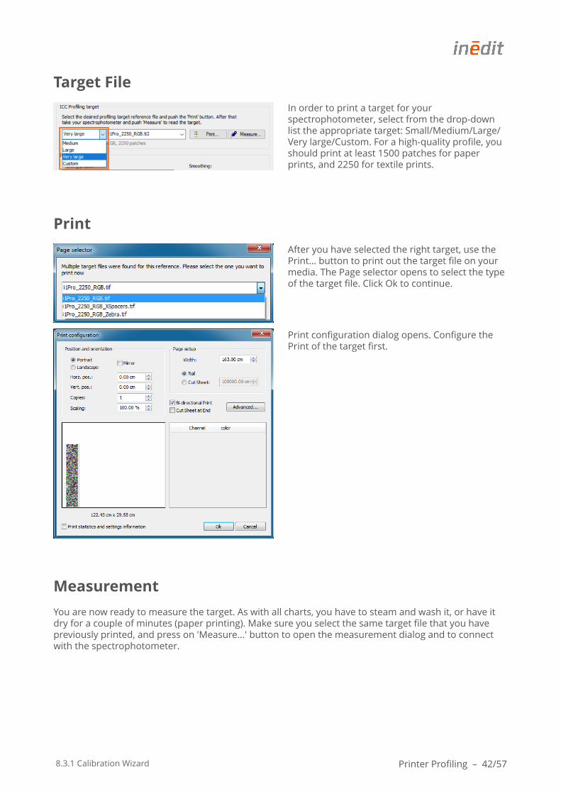
In order to print a target for your spectrophotometer, select from the drop-down list the appropriate target: Small/Medium/Large/Very large/Custom. For a high-quality profile, you should print at least 1500 patches for paper prints, and 2250 for textile prints.
After you have selected the right target, use the Print… button to print out the target file on your media. The Page selector opens to select the type of the target file. Click Ok to continue.
Print configuration dialog opens. Configure the Print of the target first.
Measurement
You are now ready to measure the target. As with all charts, you have to steam and wash it, or have it dry for a couple of minutes (paper printing). Make sure you select the same target file that you have previously printed, and press on 'Measure...' button to open the measurement dialog and to connect with the spectrophotometer.
8.3.1 Calibration Wizard Printer Profiling – 43/57
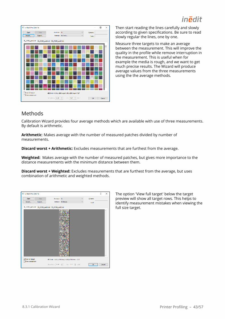
Then start reading the lines carefully and slowly according to given specifications. Be sure to read slowly regular the lines, one by one.
Measure three targets to make an average between the measurement. This will improve the quality in the profile while remove interruption in the measurement. This is useful when for example the media is rough, and we want to get much precise results. The Wizard will produce average values from the three measurements using the the average methods.
MethodsCalibration Wizard provides four average methods which are available with use of three measurements. By default is arithmetic.
Arithmetic: Makes average with the number of measured patches divided by number of measurements.
Discard worst + Arithmetic: Excludes measurements that are furthest from the average.
Weighted: Makes average with the number of measured patches, but gives more importance to the distance measurements with the minimum distance between them.
Discard worst + Weighted: Excludes measurements that are furthest from the average, but uses combination of arithmetic and weighted methods.
The option 'View full target' below the target preview will show all target rows. This helps to identify measurement mistakes when viewing the full size target.
8.3.1 Calibration Wizard Printer Profiling – 44/57
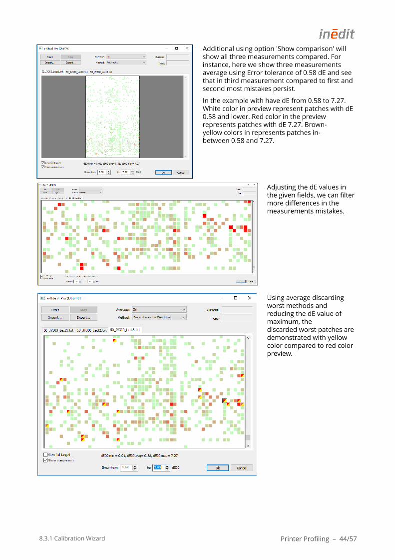
Additional using option 'Show comparison' will show all three measurements compared. For instance, here we show three measurements average using Error tolerance of 0.58 dE and see that in third measurement compared to first and second most mistakes persist.
In the example with have dE from 0.58 to 7.27. White color in preview represent patches with dE 0.58 and lower. Red color in the preview represents patches with dE 7.27. Brown-yellow colors in represents patches in-between 0.58 and 7.27.
Adjusting the dE values in the given fields, we can filter more differences in the measurements mistakes.
Using average discarding worst methods and reducing the dE value of maximum, the discarded worst patches are demonstrated with yellow color compared to red color preview.
8.3.1 Calibration Wizard Printer Profiling – 45/57
Pressing right-click mouse on the red square it opens the Spectrum visor showing the spectral curve of the selected chart patch compared between three measurements.
When the measurement is completed you will be asked to generate the profile with internal application profiler. Gradient Few will be taken by default when allowing the wizard to generate the profile after measurements are completed. More info about other smoothing gradients are described in next section.
Smoothing
With this option you can specify a certain amount to smooth out error measurements, although much of it is avoided by choosing to do three measurements of each test file, as the CW8 has newly incorporated. Broadly speaking, the more you smooth a profile the less precise this will be, so smoothing should apply only if the global precision of an ICC profile is maintained, and the most important aim is to achieve smoother gradients in printing. The options for smoothing are, in general terms:
None : should be used when measurements are good, as with paper Few : can be selected for stable readings on dense, low-structured textiles Normal : would apply with unstable measurements on structured textiles High : is only to be selected for extremely structured textiles, like towels. This gradient is not recommended to use, as it implies heavy smoothing.
Profiling presets
For the standard ink setup there are 3 presets available:
• Default RGB profile• Color matching RGB profile • Color matching RGB profile (OBA)
Default RGB profile is used in standard print flow, which relates to Perceptual rendering intent. It compresses the total gamut from one color space into the gamut of color space when one or more colors in the original image is out of the gamut of the destination color space. This preserves the visual relationship between colors by shrinking the entire color space and shifting all colors, including those that were in gamut.
Color matching RGB profile is used in printers workflows, which relates to Saturation rendering intent. It reproduces the original image color saturation when converting into the target color space. In this approach, the relative saturation of colors is maintained from gamut to gamut. Color matching RGB
8.3.1 Calibration Wizard Printer Profiling – 46/57
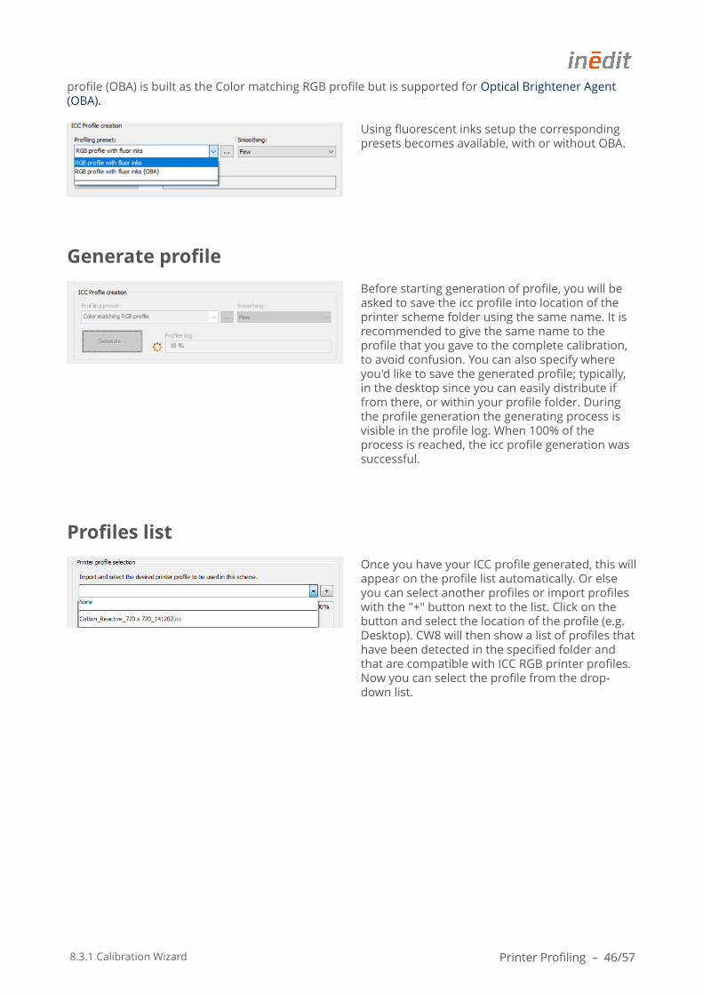
profile (OBA) is built as the Color matching RGB profile but is supported for Optical Brightener Agent (OBA).
Using fluorescent inks setup the corresponding presets becomes available, with or without OBA.
Generate profile
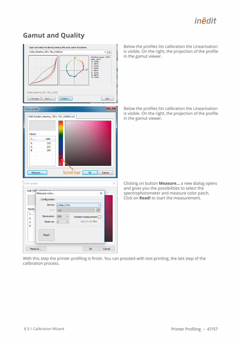
Before starting generation of profile, you will be asked to save the icc profile into location of the printer scheme folder using the same name. It is recommended to give the same name to the profile that you gave to the complete calibration, to avoid confusion. You can also specify where you'd like to save the generated profile; typically, in the desktop since you can easily distribute if from there, or within your profile folder. During the profile generation the generating process is visible in the profile log. When 100% of the process is reached, the icc profile generation was successful.
Profiles list
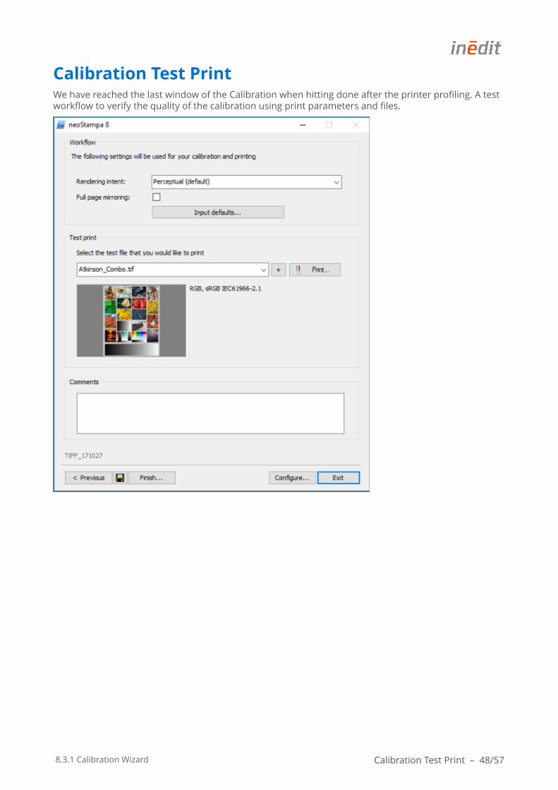
Once you have your ICC profile generated, this will appear on the profile list automatically. Or else you can select another profiles or import profiles with the "+" button next to the list. Click on the button and select the location of the profile (e.g. Desktop). CW8 will then show a list of profiles that have been detected in the specified folder and that are compatible with ICC RGB printer profiles. Now you can select the profile from the drop-down list.
8.3.1 Calibration Wizard Printer Profiling – 47/57
Gamut and Quality
Below the profiles list calibration the Linearisation is visible. On the right, the projection of the profile in the gamut viewer.
Below the profiles list calibration the Linearisation is visible. On the right, the projection of the profile in the gamut viewer.
Clicking on button Measure… a new dialog opens and gives you the possibilities to select the spectrophotometer and measure color patch. Click on Read! to start the measurement.
With this step the printer profiling is finish. You can proceed with test printing, the last step of the calibration process.
8.3.1 Calibration Wizard Calibration Test Print – 48/57
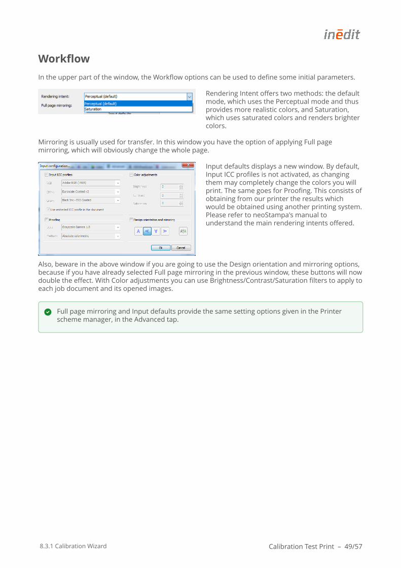
Calibration Test PrintWe have reached the last window of the Calibration when hitting done after the printer profiling. A test workflow to verify the quality of the calibration using print parameters and files.
8.3.1 Calibration Wizard Calibration Test Print – 49/57
Workflow
In the upper part of the window, the Workflow options can be used to define some initial parameters.
Rendering Intent offers two methods: the default mode, which uses the Perceptual mode and thus provides more realistic colors, and Saturation, which uses saturated colors and renders brighter colors.
Mirroring is usually used for transfer. In this window you have the option of applying Full page mirroring, which will obviously change the whole page.
Input defaults displays a new window. By default, Input ICC profiles is not activated, as changing them may completely change the colors you will print. The same goes for Proofing. This consists of obtaining from our printer the results which would be obtained using another printing system. Please refer to neoStampa's manual to understand the main rendering intents offered.
Also, beware in the above window if you are going to use the Design orientation and mirroring options, because if you have already selected Full page mirroring in the previous window, these buttons will now double the effect. With Color adjustments you can use Brightness/Contrast/Saturation filters to apply to each job document and its opened images.
Full page mirroring and Input defaults provide the same setting options given in the Printer scheme manager, in the Advanced tap.
8.3.1 Calibration Wizard Calibration Test Print – 50/57
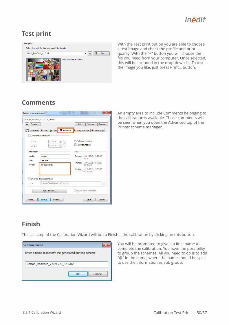
Test print
With the Test print option you are able to choose a test image and check the profile and print quality. With the "+" button you will choose the file you need from your computer. Once selected, this will be included in the drop-down list.To test the image you like, just press Print… button.
Comments
An empty area to include Comments belonging to the calibration is available. Those comments will be seen when you open the Advanced tap of the Printer scheme manager.
Finish
The last step of the Calibration Wizard will be to Finish… the calibration by clicking on this button.
You will be prompted to give it a final name to complete the calibration. You have the possibility to group the schemes. All you need to do is to add "@" in the name, where the name should be split to use the information as sub group.

8.3.1 Calibration Wizard Calibration Test Print – 51/57
Once the wizard is closed, your new calibration will automatically become available in the schemes list, in the Printer scheme manager in neoStampa. The Browse... button on the left will direct you to all your saved schemes.
If no other roots have been expressly selected, the usual path is: /neoStampa 8.X/Color/Printername/Calibration name. A shortcut to reach this folder is using the Browse… button.
8.3.1 Calibration Wizard Printer Consistency Test – 52/57
Printer Consistency TestThis function is new in respect to the Calibration wizard 7. This is a very useful tool to check if the profiles that you have already generated still keep the same quality and the printer consistency is stabile. The main purpose of re-profiling with Calibration Wizard 8.3 is to establish a quality control of the master calibration. Specially after a period of time after the calibration some differences of unseasonal or other conditions can appear. Also when paper roles of same types are changed or/and inks of the same types are re-filled in the machine.Re-profiling is based on the full calibration process and will always match the values back to the measured values of the master calibration profile, which is the done as the first printer calibration with its inks and media. The master profile won't be changed and the tool will generate a new profile.
Before starting
As in the full calibration process, we recommend to pay attention on following points.
1. Pay attention in nozzle print quality in your digital machine. Make sure to do the nozzle check before you start a new calibration.
2. Re-profiling test chart must be printed UNI - directional, the same condition as done with the first calibration.
3. Printing always in same direction (horizontal OR vertical) to secure the same printing environment during the calibration process and making an average in neoStampa 8, which means reading two target charts.
That following explained action tool is useful to recheck the profile and printer consistency after some period of time uses. If you need to change inks, or media, this re-profiling is not the tool to do as you should make a full new calibration. Nevertheless, to reach the best result of your profile, the absolute recommendation is to start a new calibration. Be aware of DeltaE changes in the white of the media, which means that some changes appears on the fabric or paper between re-profiling and the first calibration. The important value is the DeltaE of average, which is acceptable between 3 and 4 . With extremely high values we recommend to make a new full calibration.
8.3.1 Calibration Wizard Printer Consistency Test – 53/57
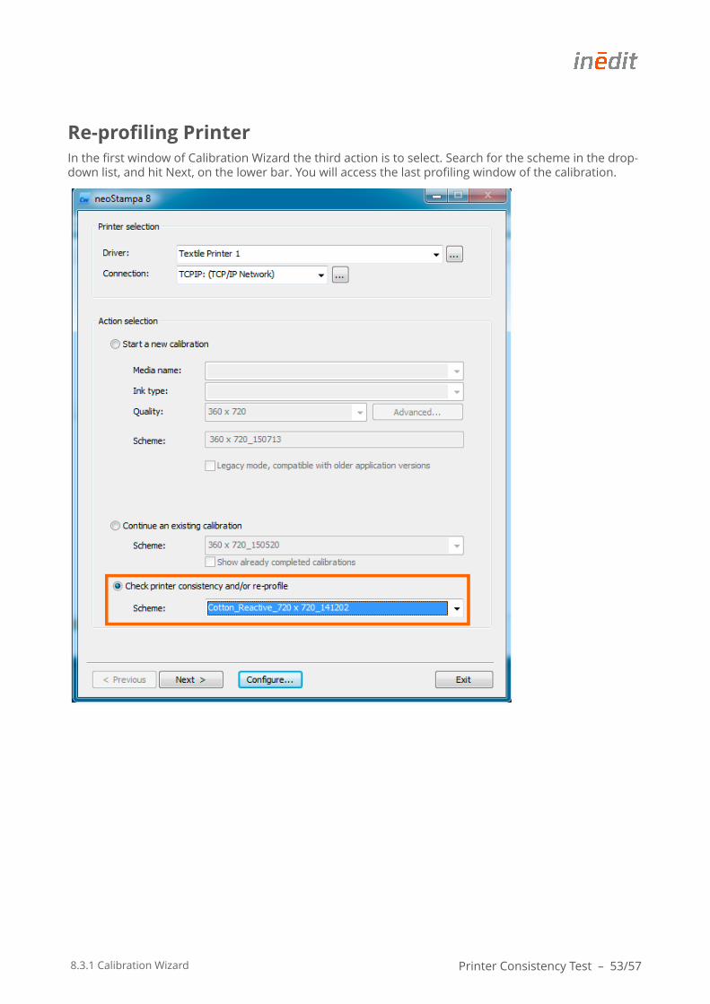
Re-profiling PrinterIn the first window of Calibration Wizard the third action is to select. Search for the scheme in the drop-down list, and hit Next, on the lower bar. You will access the last profiling window of the calibration.
8.3.1 Calibration Wizard Printer Consistency Test – 54/57
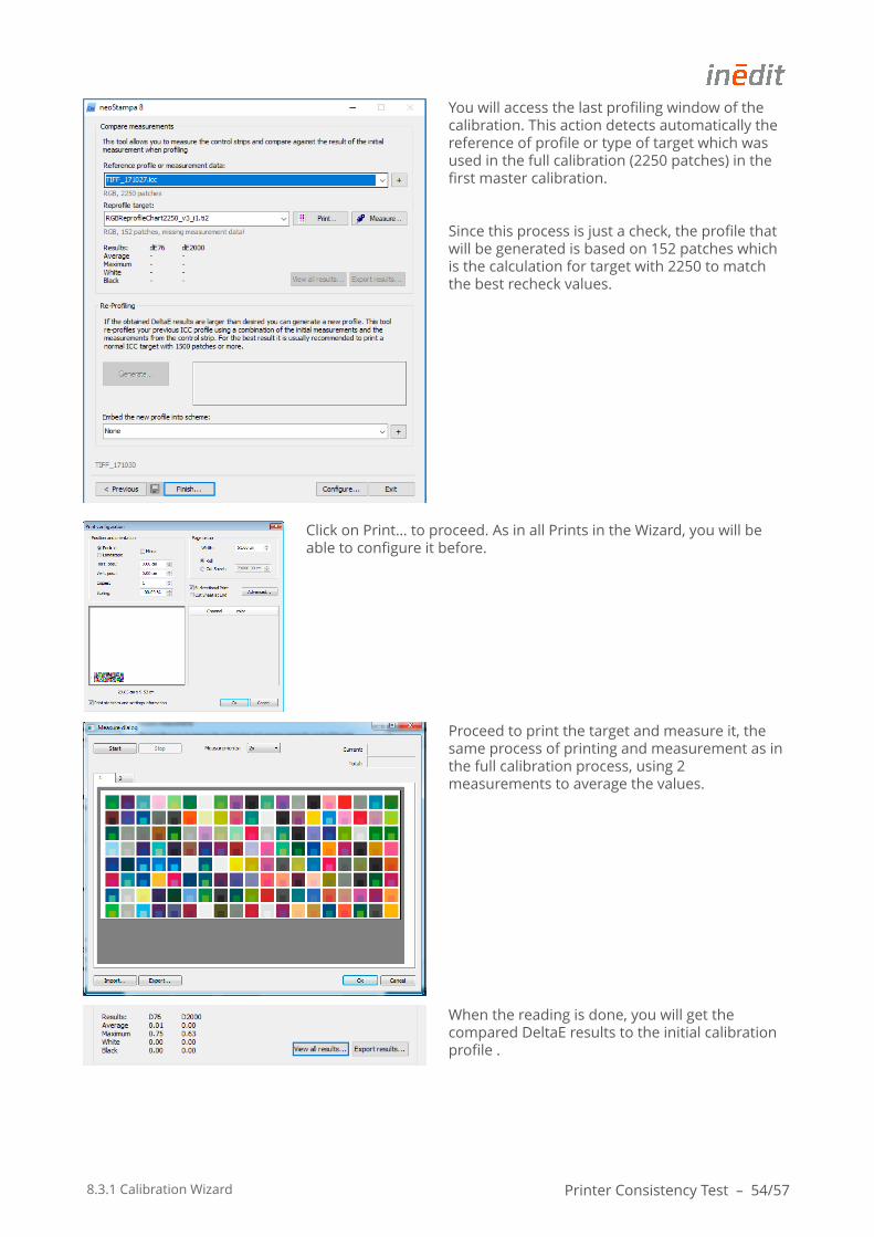
You will access the last profiling window of the calibration. This action detects automatically the reference of profile or type of target which was used in the full calibration (2250 patches) in the first master calibration.
Since this process is just a check, the profile that will be generated is based on 152 patches which is the calculation for target with 2250 to match the best recheck values.
Click on Print… to proceed. As in all Prints in the Wizard, you will be able to configure it before.
Proceed to print the target and measure it, the same process of printing and measurement as in the full calibration process, using 2 measurements to average the values.
When the reading is done, you will get the compared DeltaE results to the initial calibration profile .
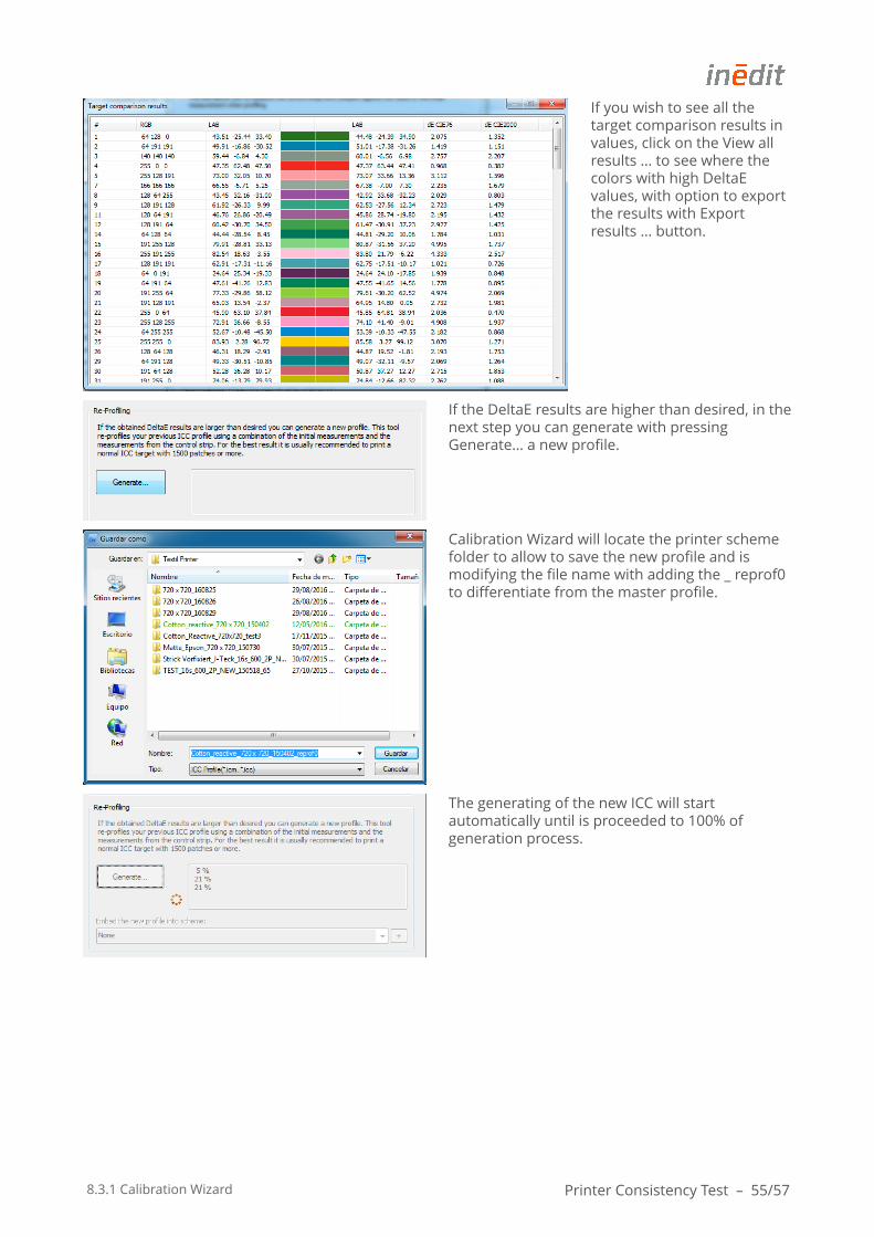
8.3.1 Calibration Wizard Printer Consistency Test – 55/57
If you wish to see all the target comparison results in values, click on the View all results … to see where the colors with high DeltaE values, with option to export the results with Export results … button.
If the DeltaE results are higher than desired, in the next step you can generate with pressing Generate… a new profile.
Calibration Wizard will locate the printer scheme folder to allow to save the new profile and is modifying the file name with adding the _ reprof0 to differentiate from the master profile.
The generating of the new ICC will start automatically until is proceeded to 100% of generation process.
8.3.1 Calibration Wizard Printer Consistency Test – 56/57
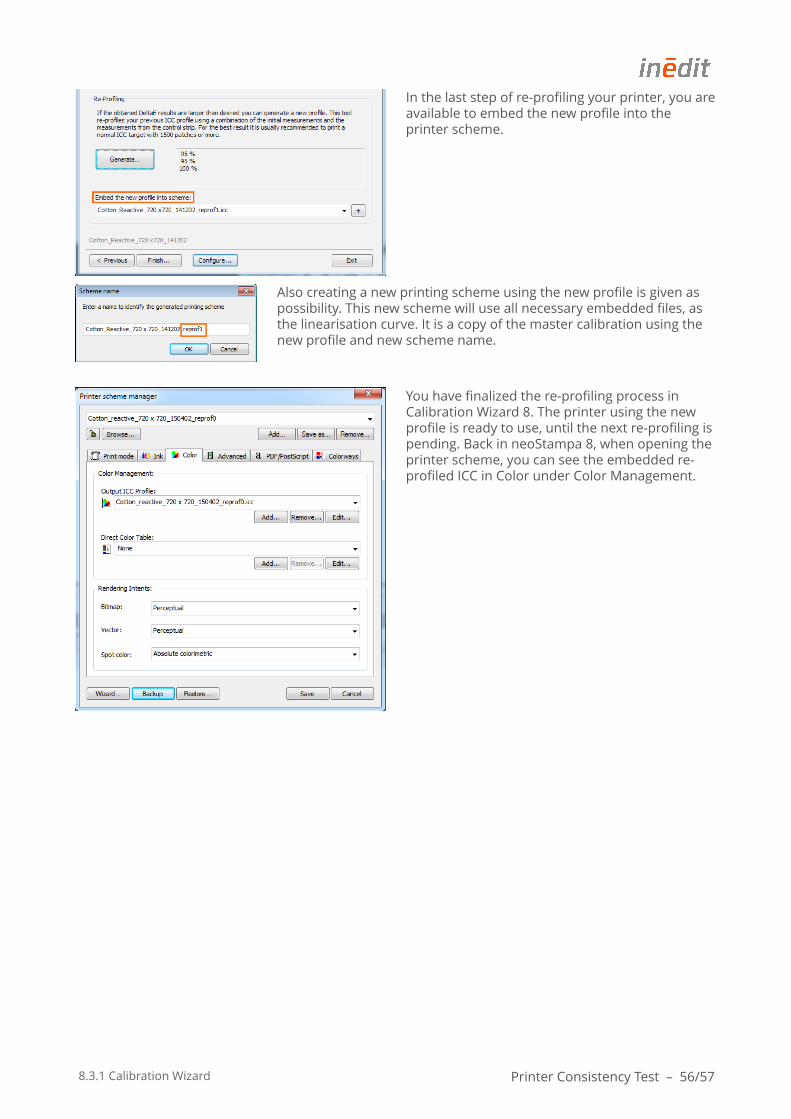
In the last step of re-profiling your printer, you are available to embed the new profile into the printer scheme.
Also creating a new printing scheme using the new profile is given as possibility. This new scheme will use all necessary embedded files, as the linearisation curve. It is a copy of the master calibration using the new profile and new scheme name.
You have finalized the re-profiling process in Calibration Wizard 8. The printer using the new profile is ready to use, until the next re-profiling is pending. Back in neoStampa 8, when opening the printer scheme, you can see the embedded re-profiled ICC in Color under Color Management.
8.3.1 Calibration Wizard Calibration Schemes Backup – 57/57
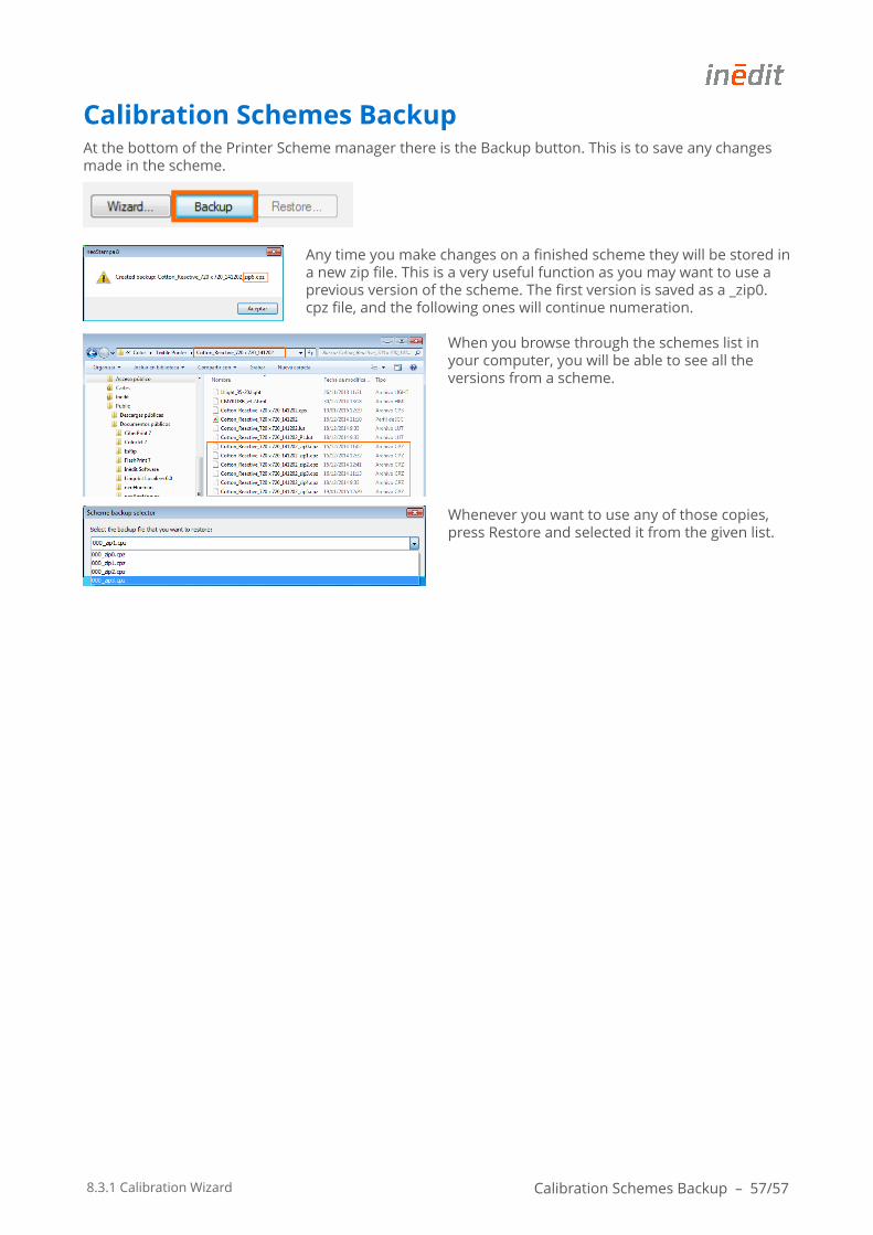
Calibration Schemes BackupAt the bottom of the Printer Scheme manager there is the Backup button. This is to save any changes made in the scheme.
Any time you make changes on a finished scheme they will be stored in a new zip file. This is a very useful function as you may want to use a previous version of the scheme. The first version is saved as a _zip0. cpz file, and the following ones will continue numeration.
When you browse through the schemes list in your computer, you will be able to see all the versions from a scheme.
Whenever you want to use any of those copies, press Restore and selected it from the given list.


![32LD350 - Dtv It Solutions Ltd.1].pdf · FEATURES • High Definition Resolution • 70,000:1 Dynamic Contrast Ratio • Picture Wizard II (Easy Picture Calibration) • Smart Energy](https://static.fdocuments.net/doc/165x107/5a9de0357f8b9a4a238ba533/32ld350-dtv-it-solutions-ltd-1pdffeatures-high-definition-resolution-.jpg)


