8.19 Distillation: Basic Controls - Freetwanclik.free.fr/electricity/IEPOPDF/1081ch8_19.pdf ·...
35
1820 8.19 Distillation: Basic Controls H. L. HOFFMAN, D. E. LUPFER (1970) L. A. KANE (1985) B. A. JENSEN (1995) B. A. JENSEN, B. G. LIPTÁK (2005) INTRODUCTION Distillation is the most common class of separation processes and one of the better understood unit operations. It is an energy-separating-agent equilibrium process that uses the dif- ference in relative volatility, or differences in boiling points, of the components to be separated. It is the most widely used method of separation in the process industries. The distillation process will most often be the choice of separation unless the following conditions exist: • Thermal damage can occur to the product. • A separation factor is too close to unity. • Extreme conditions of temperature or pressure are needed. • Economic value of products is low relative to energy costs. Control involves the manipulation of the material and energy balances in the distillation equipment to affect product composition and purity. Difficulties arise because of the mul- titude of potential variable interactions and disturbances that can exist in single-column fractionators and in the process that the column is a part of. Even seemingly identical columns will exhibit great diversity of operation in the field. Therefore, this section will not attempt to provide control strategies that can be applied to columns in a “cookbook” fashion. Instead, discussion will begin with a basic description of the distillation process and equipment, followed by techniques used to derive a mathe- matical column model. The presentation in this section will then describe meth- ods to evaluate interactions and alternative control strategies; control models used for some product quality, pressure, and feed flow control strategies; and finally some common feed- forward advanced regulatory control strategies commonly used in the regulation of fractionators. The goal of this section is to provide the process control engineer with the tools necessary to design unique control strategies that will match the specific requirements of distil- lation columns. General Considerations Distillation separates a mixture by taking advantage of the difference in the composition of a liquid and that of the vapor formed from that liquid. In the processing industries, distilla- tion is widely used to isolate and purify volatile materials. Thus, good process control of the distillation process is vital to maximize the production of satisfactory purity end products. Although engineers often speak of controlling a distilla- tion tower, many of the instruments actually are used to control the auxiliary equipment associated with the tower. For this reason, the equipment used in distillation will be discussed. V V F L F Q R i or L i T R R or L D L F B Q V Flow sheet symbol © 2006 by Béla Lipták
-
Upload
truongdung -
Category
Documents
-
view
230 -
download
2
Transcript of 8.19 Distillation: Basic Controls - Freetwanclik.free.fr/electricity/IEPOPDF/1081ch8_19.pdf ·...

1820
8.19 Distillation: Basic Controls
H. L. HOFFMAN, D. E. LUPFER
(1970)
L. A. KANE
(1985)
B. A. JENSEN
(1995)
B. A. JENSEN, B. G. LIPTÁK
(2005)
INTRODUCTION
Distillation is the most common class of separation processesand one of the better understood unit operations. It is anenergy-separating-agent equilibrium process that uses the dif-ference in relative volatility, or differences in boiling points,of the components to be separated. It is the most widely usedmethod of separation in the process industries. The distillationprocess will most often be the choice of separation unless thefollowing conditions exist:
• Thermal damage can occur to the product.• A separation factor is too close to unity.• Extreme conditions of temperature or pressure are
needed.• Economic value of products is low relative to energy
costs.
Control involves the manipulation of the material andenergy balances in the distillation equipment to affect productcomposition and purity. Difficulties arise because of the mul-titude of potential variable interactions and disturbances thatcan exist in single-column fractionators and in the processthat the column is a part of.
Even seemingly identical columns will exhibit greatdiversity of operation in the field. Therefore, this section willnot attempt to provide control strategies that can be applied
to columns in a “cookbook” fashion. Instead, discussion willbegin with a basic description of the distillation process andequipment, followed by techniques used to derive a mathe-matical column model.
The presentation in this section will then describe meth-ods to evaluate interactions and alternative control strategies;control models used for some product quality, pressure, andfeed flow control strategies; and finally some common feed-forward advanced regulatory control strategies commonlyused in the regulation of fractionators.
The goal of this section is to provide the process controlengineer with the tools necessary to design unique controlstrategies that will match the specific requirements of distil-lation columns.
General Considerations
Distillation separates a mixture by taking advantage of thedifference in the composition of a liquid and that of the vaporformed from that liquid. In the processing industries, distilla-tion is widely used to isolate and purify volatile materials.Thus, good process control of the distillation process is vitalto maximize the production of satisfactory purity end products.
Although engineers often speak of controlling a distilla-tion tower, many of the instruments actually are used tocontrol the auxiliary equipment associated with the tower.For this reason, the equipment used in distillation will bediscussed.
V
V
F
LF
Q
Ri or Li
TR R or L D
LF B
Q
V
Flow sheet symbol
© 2006 by Béla Lipták
8.19 Distillation: Basic Controls
1821
DISTILLATION EQUIPMENT
There are some basic variations to the distillation process.One such basic difference is between continuous and batchdistillation. The main difference between these processes isthat in continuous distillation the feed concentration is rela-tively constant, while in batch distillation it is rich in lightcomponents at the beginning and lean in light componentsat the end. While batch distillation is also described in thissection, the emphasis is on the continuous processes.
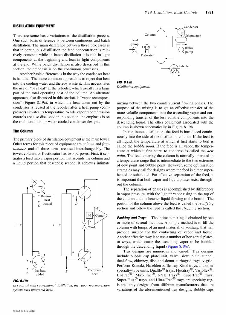
Another basic difference is in the way the condenser heatis handled. The more common approach is to reject that heatinto the cooling water and thereby waste it. This necessitatesthe use of “pay heat” at the reboiler, which usually is a largepart of the total operating cost of the column. An alternateapproach, also discussed in this section, is “vapor recompres-sion” (Figure 8.19a), in which the heat taken out by thecondenser is reused at the reboiler after a heat pump (com-pressor) elevates its temperature. While vapor recompressioncontrols are also discussed in this section, the emphasis is onthe traditional air- or water-cooled condenser designs.
The Column
The primary piece of distillation equipment is the main tower.Other terms for this piece of equipment are
column
and
frac-tionator
, and all three terms are used interchangeably. Thetower, column, or fractionator has two purposes: First, it sep-arates a feed into a vapor portion that ascends the column anda liquid portion that descends; second, it achieves intimate
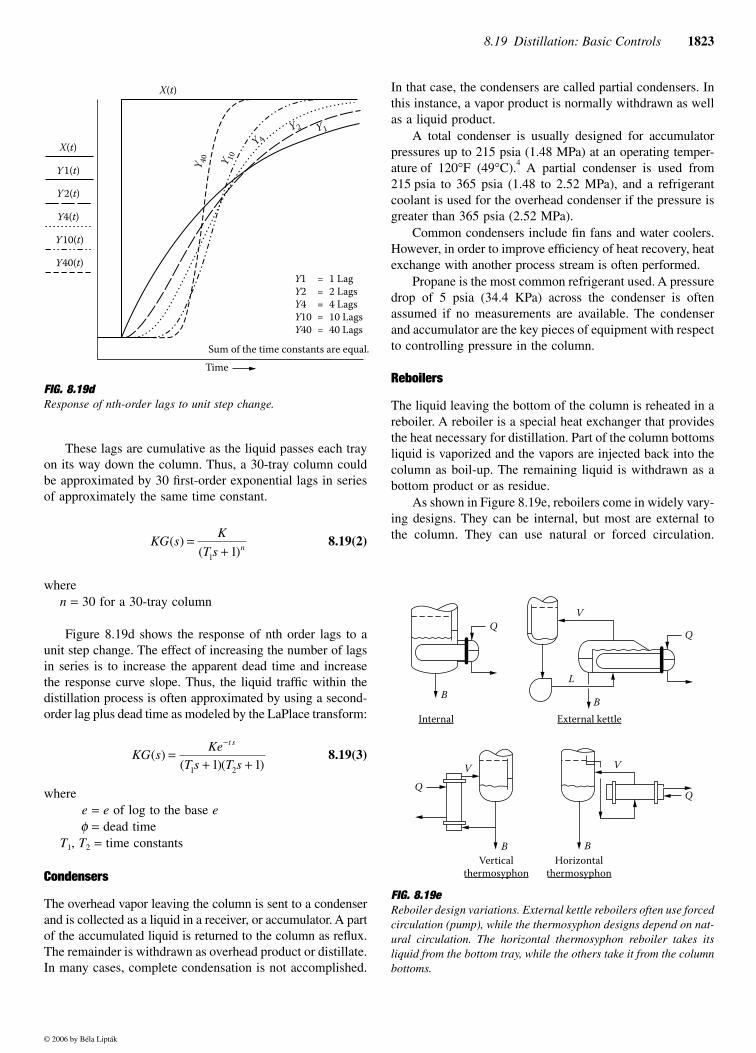
mixing between the two countercurrent flowing phases. Thepurpose of the mixing is to get an effective transfer of themore volatile components into the ascending vapor and cor-responding transfer of the less volatile components into thedescending liquid. The other equipment associated with thecolumn is shown schematically in Figure 8.19b.
In continuous distillation, the feed is introduced contin-uously into the side of the distillation column. If the feed isall liquid, the temperature at which it first starts to boil iscalled the
bubble point
. If the feed is all vapor, the temper-ature at which it first starts to condense is called the
dewpoint
. The feed entering the column is normally operated ina temperature range that is intermediate to the two extremesof dew point and bubble point. However, some optimizationstrategies may call for designs where the feed is either super-heated or subcooled. For effective separation of the feed, itis important that both vapor and liquid phases exist through-out the column.
The separation of phases is accomplished by differencesin vapor pressure, with the lighter vapor rising to the top ofthe column and the heavier liquid flowing to the bottom. Theportion of the column above the feed is called the
rectifying
section and below the feed is called the
stripping
section.
Packing and Trays
The intimate mixing is obtained by oneor more of several methods. A simple method is to fill thecolumn with lumps of an inert material, or
packing
, that willprovide surface for the contacting of vapor and liquid.Another effective way is to use a number of horizontal plates,or
trays
, which cause the ascending vapor to be bubbledthrough the descending liquid (Figure 8.19c).
Tray designs are numerous and varied.
1
Tray designsinclude bubble cap plate unit, valve, sieve plate, tunnel,dual-flow, chimney, disc-and-donut, turbogrid trays, v-grid,Perform-Kontakt, Haselden baffle tray, Kittel trays, and otherspecialty-type units. Dualflo® trays, Flexitray®, Varioflex®,Bi-Frac®, Max-Frac®, NYE Trays®, Superfrac® trays,Super-Flux® trays, and Ultra-Frac® trays are specialty reg-istered tray designs from different manufacturers that arevariations of the aforementioned tray designs. Bubble caps
FIG. 8.19a
In contrast with conventional distillation, the vapor recompressionsystem uses recovered heat.
M
Removed
heat
wastedD
F F
B BPay heat
added
Recovered
heat
Work
D
Compr.
FIG. 8.19b
Distillation equipment.
Feed
pump
Preheater
Column
Reboiler
Reflux
pump
Condenser
Accumulator
© 2006 by Béla Lipták

1822
Control and Optimization of Unit Operations
and sieve trays are the most common designs used in distil-lation applications.
Many different types of packings are available.
2
They arenormally classified as random or stacked. Random packingsare those that are dumped into the containing shell. Raschigrings, Berl saddles, Intalox saddles, and Pall rings are themost common random packings and come in various sizesfrom
1
/
2
to 3
1
/
2
in (1.25 to 9 cm). Stacked packings, also known as grid or stacked packing,
include large-sized Raschig rings and Lessing rings. Packingsgenerally give lower pressure drops at the cost of higherinstallation costs. They are made of ceramic, plastic, or metal,depending upon the type of packing and the intended appli-cation. Other packings such as Maspac®, HyPak®, Teller-ette®, IMTP® FLEXIPAC® KATAMAX®: FLEXIGRID®-2,-3, and -4, and KOCH-GLITSCH GRID® EF-25A are spe-cialty registered packings from different manufacturers thatare just variations of the aforementioned packings.
When deciding between the use of trays and packing, thefollowing factors should be considered:
3
• Because of liquid dispersion difficulties in packed tow-ers, the design of plate towers is considerably morereliable and requires less safety factor when the ratioof liquid mass velocity to gas mass velocity is low.
• Towers using trays can be designed to handle widerranges of liquid rates without flooding.
• Towers using trays are more accessible for cleaning.• Towers using trays are preferred if interstage cooling
or heating is needed because of lower installation costsof delivery piping.
• Towers using trays have a lower total dry weight,though total weight with liquid hold-up is probablyequal.
• Towers using trays are preferred when large tempera-ture changes are expected because of thermal expan-sion or when contraction may crush packing.
• Design information for towers using trays is generallymore readily available and more reliable.
• Packed towers are cheaper and easier to construct thanplate towers if highly corrosive fluid must be handled.
• Diameters of packed towers are generally designed tobe less than 4 ft, while plate tower diameters aredesigned to be more than 2ft.
• Packed towers are preferred if the liquids have a largetendency to foam.
• The amount of liquid hold-up is considerably less inpacked towers.
• The pressure drop through packed towers may be lessthan for plate towers performing the same service, mak-ing packed towers desirable for vacuum distillation.
Thus, generally, trays work better in applications requir-ing high flow, such as those encountered in high-pressuredistillation columns, such as depropanizers, debutanizers,xylene purification columns, and the like. Packing works bestat lower flow parameters, as the low-pressure drop of struc-tured packing makes it very attractive for use in vacuumcolumns or ethylbenzene recycle columns of styrene plants.
The contacting between the vapor and liquid in a single-stage contacting device will not produce total equilibrium.The relationship between ideal and actual performance is theefficiency that translates the number of ideal separation stagesinto actual finite stages that must be used to accomplish thedesired final separation. Efficiency varies, not only with thetype of mixing method used (e.g., packing or trays), but alsowith fluid rates, fluid properties, column diameter, and oper-ating pressure.
The influence of plate efficiency in the operation ofthe distillation tower becomes important in the control of theoverhead composition. Because plate efficiencies increasewith increased vapor velocities, the influence of the reflux-to-feed ratio on overhead composition becomes a nonlinearrelationship.
Dynamics
Dynamic considerations due to liquid hold-upon the trays comes into play when discussing distillationcontrol. Because the liquid on each tray must overflow itsweir and work its way down the column due to tray orpacking hydraulics, this change will not be seen at the bot-toms of the tower until some time has passed. The exactdynamics depend on column size, type of tray, number oftrays, and tray spacing. The hold-up at each tray as shownin Figure 8.19c can be modeled by the LaPlace transform ofthe form
8.19(1)
where
KG
(s)
=
transfer function
K
=
system gain
T
1
=
time constant
S
=
LaPlace transfer operator
FIG. 8.19c
Intimate contact and therefore equilibrium is obtained as the vaporbubbles ascend through the liquid held up on each tray, as the liquiddescends down the column
.
L
L
L
KG sK
T s( )
( )=
+1 1
© 2006 by Béla Lipták
8.19 Distillation: Basic Controls
1823
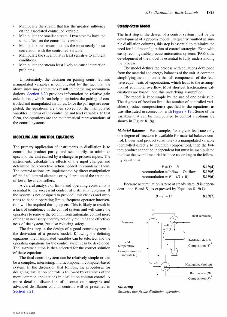
These lags are cumulative as the liquid passes each trayon its way down the column. Thus, a 30-tray column couldbe approximated by 30 first-order exponential lags in seriesof approximately the same time constant.
8.19(2)
where
n
=
30 for a 30-tray column
Figure 8.19d shows the response of nth order lags to aunit step change. The effect of increasing the number of lagsin series is to increase the apparent dead time and increasethe response curve slope. Thus, the liquid traffic within thedistillation process is often approximated by using a second-order lag plus dead time as modeled by the LaPlace transform:
8.19(3)
where
e
=
e
of log to the base
e
φ
=
dead time
T
1
,
T
2
=
time constants
Condensers
The overhead vapor leaving the column is sent to a condenserand is collected as a liquid in a receiver, or accumulator. A partof the accumulated liquid is returned to the column as reflux.The remainder is withdrawn as overhead product or distillate.In many cases, complete condensation is not accomplished.
In that case, the condensers are called partial condensers. Inthis instance, a vapor product is normally withdrawn as wellas a liquid product.
A total condenser is usually designed for accumulatorpressures up to 215 psia (1.48 MPa) at an operating temper-ature
of 120
°
F (49
°
C).
4
A partial condenser is used from215 psia to 365 psia (1.48 to 2.52 MPa), and a refrigerantcoolant is used for the overhead condenser if the pressure isgreater than 365 psia (2.52 MPa).
Common condensers include fin fans and water coolers.However, in order to improve efficiency of heat recovery, heatexchange with another process stream is often performed.
Propane is the most common refrigerant used. A pressuredrop of 5 psia (34.4 KPa) across the condenser is oftenassumed if no measurements are available. The condenserand accumulator are the key pieces of equipment with respectto controlling pressure in the column.
Reboilers
The liquid leaving the bottom of the column is reheated in areboiler. A reboiler is a special heat exchanger that providesthe heat necessary for distillation. Part of the column bottomsliquid is vaporized and the vapors are injected back into thecolumn as boil-up. The remaining liquid is withdrawn as abottom product or as residue.
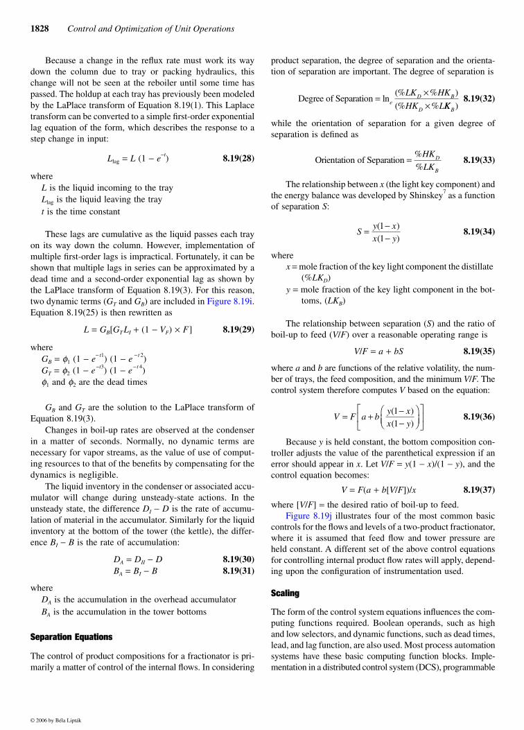
As shown in Figure 8.19e, reboilers come in widely vary-ing designs. They can be internal, but most are external tothe column. They can use natural or forced circulation.
FIG. 8.19d
Response of nth-order lags to unit step change.
X(t)
Y 1(t)
Y 2(t)
Y4(t)
Y10(t)
Y40(t)
X(t)
Y1Y 2
Y 10
Y 4
Y 40
Y1 = 1 Lag
Y2 = 2 Lags
Y4 = 4 Lags
Y10 = 10 Lags
Y40 = 40 Lags
Time
Sum of the time constants are equal.
KG sK
T s n( )
( )=
+1 1
KG sKe
T s T s
t s
( )( )( )
=+ +
−
1 21 1
FIG. 8.19e
Reboiler design variations. External kettle reboilers often use forcedcirculation (pump), while the thermosyphon designs depend on nat-ural circulation. The horizontal thermosyphon reboiler takes itsliquid from the bottom tray, while the others take it from the columnbottoms.
B
QV
Q
B
L
Internal External kettle
V
Q
BHorizontal
thermosyphon
Vertical
thermosyphon
QV
B
© 2006 by Béla Lipták

1824
Control and Optimization of Unit Operations
The kettle reboiler is the most common external forced cir-culation design.
Vertical and horizontal thermosiphon reboilers operateby natural circulation. In these, flow is induced by the hydro-static pressure imbalance between the liquid inside the towerand the two-phase mixture in the reboiler tubes. In forcedcirculation reboilers, a pump is used to ensure circulation ofthe liquid past the heat transfer surface. Reboilers may bedesigned so that boiling occurs inside vertical tubes, insidehorizontal tubes, or on the shell side.
A newer development in reboiler design is the conceptself-cleaning shell-and-tube heat exchangers for applicationswhere heat exchange surfaces are prone to fouling by theprocess fluid. Common heat sources include hot oil, steam,or fuel gas (fired reboilers). Cases where simple heat exchangewith another process stream is used for efficiency of heatrecovery are common. Thus, the choice of instrumentation tocontrol heat addition to the tower depends upon the type ofreboiler used.
Interheaters/Intercoolers
In some cases, additional vapor or liquid is withdrawn fromthe column at points above or below the point at which thefeed enters. All or a portion of this sidestream can be usedas intermediate product. Sometimes, economical columndesign dictates that the sidestream be cooled and returned tothe column to furnish localized reflux. The equipment thatdoes this is called a sidestream cooler, or intercooler. Multi-product fractionators often have these intercoolers in a pump-around stream.
At other times, localized heat is required. Then, some ofthe liquid in the column is removed and passed through asidestream reboiler, or interheater, before being returned tothe column. Interheaters are usually utilized in cryogenicdemethanizers.
Often the feed is preheated before entering the column.Common preheat mediums include the bottoms product orlow-pressure steam. Preheating is often a convenient methodto recover heat that would otherwise be wasted.
Column Variables
Controlling a fractionator requires the identifying of the con-trolled, manipulated, and load variables (Figure 8.19f). Con-trolled variables are those variables that must be maintainedat a precise value to satisfy column objectives. These nor-mally include product compositions, column temperatures,column pressure, and tower and accumulator levels.
Manipulated variables are those variables that can bechanged in order to maintain the controlled variables at theirdesired values. Common examples include reflux flow, cool-ant flow, heating medium flow, and product flows. Load vari-ables are those variables that provide disturbances to thecolumn. Common examples include feed flow rate and feed
composition. Other common disturbances are steam headerpressure, feed enthalpy, environmental conditions (e.g., rain,barometric pressure, and ambient temperature), and coolanttemperature.
To handle these disturbances, column controls can be sodesigned as to make the column insensitive to these distur-bances, or secondary controls can be designed to eliminatethe disturbances. It is also important to evaluate the expectedmagnitude and duration of the likely disturbances, so thatproper control system scaling and tuning can be achieved.
Feedforward controls are designed to compensate forthese disturbance variables and are discussed later in thissection. There are other advanced control or optimizationmethods that can be designed to compensate for these dis-turbance variables. They are discussed in Section 8.21.
Pairing of Variables
The variables that should be controlledare usually obvious. They are normally identified when pro-cess objectives are defined and understood. Load variablesare also easily identified. But identification of the manipu-lated variables can be more difficult. The general guidelinesfor identifying which manipulated variables to associate withwhich controlled variables are
FIG. 8.19f
In a binary distillation process the number of independent variablesis eleven (11) and the number of defining equations is two (2).Therefore, the number of degrees of freedom is nine (9), which isthe maximum number of automatic controllers that can be used onsuch a process.
Feed
L Overhead product
(D)
(V)Steam
Bottom product
(B)
C1 = overhead temperature
C2 = overhead pressure
C3 = overhead composition
C4 = overhead flow rate
u1 = bottom temperature
u2 = bottom pressure
u3 = bottom composition
u4 = bottom flow rate
u5 = feed temperature
u6 = feed pressure
u7 = feed composition
u8 = feed per cent vapor
u9 = feed flow rate
m = steam flow rate (heat input)
Apparent
variables:
Independent
variables
2
1
2
1
2
111
11
© 2006 by Béla Lipták
8.19 Distillation: Basic Controls
1825
• Manipulate the stream that has the greatest influenceon the associated controlled variable.
• Manipulate the smaller stream if two streams have thesame effect on the controlled variable.
• Manipulate the stream that has the most nearly linearcorrelation with the controlled variable.
• Manipulate the stream that is least sensitive to ambientconditions.
• Manipulate the stream least likely to cause interactionproblems.
Unfortunately, the decision on pairing controlled andmanipulated variables is complicated by the fact that theabove rules may sometimes result in conflicting recommen-dations. Section 8.20 provides information on relative gaincalculations, which can help to optimize the pairing of con-trolled and manipulated variables. Once the pairings are com-pleted, the equations are then solved for the manipulatedvariables in terms of the controlled and load variables. In thatform, the equations are the mathematical representations ofthe control systems.
MODELING AND CONTROL EQUATIONS
The primary application of instruments in distillation is tocontrol the product purity, and secondarily, to minimizeupsets to the unit caused by a change in process inputs. Theinstruments calculate the effects of the input changes anddetermine the corrective action needed to counteract them.The control actions are implemented by direct manipulationof the final control elements or by alteration of the set pointsof lower level controllers.
A careful analysis of limits and operating constraints isessential to the successful control of distillation columns. Ifthe system is not designed to provide limit checks and over-rides to handle operating limits, frequent operator interven-tion will be required during upsets. This is likely to result ina lack of confidence in the control system and will cause theoperators to remove the column from automatic control moreoften than necessary, thereby not only reducing the effective-ness of the system, but also reducing safety.
The first step in the design of a good control system isthe derivation of a process model. Knowing the definingequations, the manipulated variables can be selected, and theoperating equations for the control system can be developed.The instrumentation is then selected for the correct solutionof these equations.
The final control system can be relatively simple or canbe a complex, interacting, multicomponent, computer-basedsystem. In the discussion that follows, the procedures fordesigning distillation controls is followed by examples of themore common applications in distillation column control. Amore detailed discussion of alternative strategies andadvanced distillation column controls will be presented inSection 8.21.
Steady-State Model
The first step in the design of a control system must be thedevelopment of a process model. Frequently omitted in sim-ple distillation columns, this step is essential to minimize theneed for field reconfiguration of control strategies. Even witheasily reconfigurable process automation systems (PASs), thedevelopment of the model is essential to fully understandingthe process.
The model defines the process with equations developedfrom the material and energy balances of the unit. A commonsimplifying assumption is that all components of the feedhave equal heats of vaporization, which leads to the assump-tion of equimolal overflow. Most shortcut fractionation cal-culations are based upon this underlying assumption.
The model is kept simple by the use of one basic rule:The degrees of freedom limit the number of controlled vari-ables (product compositions) specified in the equations, aswas illustrated in connection with Figure 8.19f. Some of thevariables that can be manipulated to control a column areshown in Figure 8.19g.
Material Balance
For example, for a given feed rate onlyone degree of freedom is available for material balance con-trol. If overhead product (distillate) is a manipulated variable(controlled directly to maintain composition), then the bot-tom product cannot be independent but must be manipulatedto close the overall material balance according to the follow-ing equations:
F
=
D
+
B
8.19(4)
Accumulation
=
Inflow
−
Outflow
8.19(5)
Accumulation
=
F
−
(
D
+
B
)
8.19(6)
Because accumulation is zero at steady state,
B
is depen-dent upon
F
and
D
, as expressed by Equation 8.19(4):
B
=
F
−
D
8.19(7)
FIG. 8.19g
Variables that fix the distillation operation.
Pressure
Feed
temperature,
Composition (Z)
and rate (F )
Reflux
rate (L)
Heat removed
Distillate rate (D)
Composition (Y)
Composition (X)
V
Heat added (boilup)
Bottom rate (B)
© 2006 by Béla Lipták

1826
Control and Optimization of Unit Operations
or if the bottoms product is the manipulated variable:
D
=
F
−
B
8.19(8)
where:
F
=
feed rate (the inflow)
D
=
overhead rate (an outflow)
B
=
bottoms rate (an outflow)
If the compositions of the feed, distillate product, andbottoms product are known, then the component materialbalance can be solved:
100
=
%
LLK
D
+
%
LK
D
+
%
HK
D
8.19(9)
D
×
%
LLK
D
=
F
× %LLKF 8.19(10)F × %LKF = D × %LKD + B × %LKB 8.19(11)
where:%LLKF = lighter than light key in the feed (mol%)
%LKF = light key in the feed (mol%)
%LLKD = lighter than light key in the distillate product
(mol%)%LKD = light key in the distillate product (mol%)
%HKD = heavy key in the distillate product (mol%)
%LKB = light key in the bottoms product (mol%)
In the most general case, the feed might have four com-ponents, having the concentrations of LLKF , LKF , HKF , andHHKF . Three of these components appear in each of thebottom and overhead products. The separation of the columnis fixed by specifying the heavy key component in the over-head product HKD and the concentration of the light keycomponent in the bottom product LKB.
Equations 8.19(9) to 8.19(11) assume no heavier thanheavy key is found in the distillate and that no lighter than lightkey is found in the bottoms. Rearranging Equation 8.19(11)gives
%LKD = (F • %LKF − B • %LKB)/D 8.19(12)
Substituting Equation 8.19(8) into Equations 8.19(10)and 8.19(12) gives
%LLKD = (F • %LLKF)/(F − Β) 8.19(13)%LKD = (F • %LKF − B • %LKB)/(F − B) 8.19(14)
Substituting Equations 8.19(13) and 8.19(14) intoEquation 8.19(9) to eliminate %LLKD and %LKD:
8.19(15)
For a given feed composition and desired product com-positions, only one bottoms-to-feed ratio, B/F (product split),will satisfy the overall and component material balances. Byfixing the bottoms flow, the distillate flow will be fixed.
However, fixing a value of product split does not fix eitherthe distillate or bottoms composition because many combi-nations of %LLKF, %LKF, %LKB, and %HKD could yield thesame value of B/F.
Energy Balance The energy balance and the separationobtained are closely related. Conceptually, product compositioncontrol can be thought of as a problem of the rate of heataddition QB at the bottom of the fractionator and the rate of heatremoval QT at the top of the column. A series of energy balancesproduces additional equations. Figure 8.19h shows a steady-state internal model of these equations.5
The vapor boil-up rate VB equals the heat QB added bythe reboiler divided by the heat of vaporization (∆H) of thebottoms product:
VB = QB /∆H 8.19(16)
The vapor rate V above the feed tray equals the vaporboil-up rate plus the vapor entering with the feed (feed rate
B FHK LLK LK
HK LKD F F
D B
/( % % % )
( % % )=
− − −− −
100
100
FIG. 8.19hEnergy balance equations can be used to describe the steady-stateheat flow model of a distillation column.
Li = L[1 + (Cp/∆H) × (To − Tr)]
B = Bi if no accumulation occurs in
the column bottoms.
D = Di if no accumulation occurs in
the accumulator
L − External reflux
Lf − Liquid flow below feed tray
Li − Internal reflux
QB − Heat addition at bottom
QT − Heat removal at top
VB − Vapor boilup rate
VF − Vapor fraction in feed
∆H − Heat of vaporization in reboiler
∆HD − Heat of condensation of distillate
∆HL − Heat of vaporization of reflux
∆HLi − Heat of condensation of
internal reflux
Lf = Li + (1 − VF) × FBi = Lf − VB
To
L @ Tr
Di = V − Li
QT
D(y)
V = VB + VF × F
F (z)
VB = QB/∆H
QB
B(x)
Material balance: F = D + Bseparation is the energy/feed
ratio of a column. For binary
process: S = y(1 − x)
x(1 − y)
Separation should be controlled
by the more pure product.
© 2006 by Béla Lipták

8.19 Distillation: Basic Controls 1827
F times vapor fraction VF , provided the feed is neither sub-cooled nor superheated):
V = VB + F × VF 8.19(17)
The internal reflux rate, that is, the liquid at the top trayof the column is derived by a heat balance around the top ofthe tower. Assuming a steady-state heat balance where theheat into the tower equals the heat out:
8.19(18)
whereCp = specific heat To = overhead vapor temperature (vapor at its dew point)L = external reflux Tr = external reflux temperatureLI = internal reflux
Tt = top tray temperature (liquid at its bubble point)
Equation 8.19(18) reduces to:
8.19(19)
Making a simplifying assumption that the tray tempera-ture equals overhead vapor temperature (i.e., the dew pointof the vapor equals the bubble point of the liquid; Tt = To)produces:
8.19(20)
or
8.19(21)
resulting in the equation
LpI /L = K2 × [1 + K1 × (Tpo − Tpr)] 8.19(22)
If a total condenser is employed, the composition of theinternal reflux and external reflux are the same, i.e.,
, so the constant K2 = 1.0. Thus,
8.19(23)
or zI = L × [1 + K1 × ∆T] 8.19(24)
Note: This equation is valid for whatever units are usedfor or ∆HL. Because specific heat and heat of vaporiza-tion are nearly always in mass units, care must be taken toaccount for density differences whenever volume units are
being used by the control equation. Also, and ∆HL shouldbe calculated near the existing pressure and temperature ofthe external reflux.
The liquid rate, LF, below the feed tray equals the internalreflux plus the liquid in the feed:
LF = LI + (1 − VF) × F 8.19(25)
The distillate rate, D, equals the vapor rate, V, above thefeed tray minus the internal reflux:
D = V − LI 8.19(26)
The bottoms rate, B, equals the liquid rate, L, minus theboil-up, VB:
B = L − VB 8.19(27)
The criterion for separation is the ratio of reflux (L) todistillate (D) flows vs. the ratio of boil-up (V) to bottoms (B)flow rates. Manipulating reflux affects separation equally aswell as manipulating boil-up, albeit in opposite directions.Consequently, only one degree of freedom exists to controlseparation. Thus, for a two-product tower, two equationsdefine the process. One is an equation describing separation,and the other is an equation for material balance.
Dynamic Model
Because the tower doesn’t always operate at steady state, itis essential to also account for the dynamics of the process.This necessitates extending the steady-state internal flowmodel and requires additional considerations. Figure 8.19ishows the internal flow model that includes dynamics.6
D H C T L H C T
L C T
D p t I L p t
p r
D I RI
L
× + × + × + ×
+ × ×
( ) ( )
( )
∆ ∆
== × + ×
+ × + × + × ×
D H C T
L H C T L C T
D p o
L p o I p t
D
L LI
( )
( ) (
∆
∆ ))
D C T T L H L H
L C T T
p t o I L L
p r o
D I
L
× × − + × − ×
+ × × − =
( )
( )
∆ ∆
0
L H L H L C T TI L L p o rI L× = × + × × −∆ ∆ ( )
L
L
H
H
C
HT Ti L
L
p
Lo r
i
L= ⋅ + ⋅ −
∆
∆ ∆1 0. ( )
∆ ∆H HL LI=
LL
K T TI
O r
=+ −[ ( )]1 1
C pL
FIG. 8.19iDynamic internal flow model.
C pL
Di = V − LiDA= Di − D
QT
D
To
L @ Tr
GT
Li = L[1 + (Cp/∆H) × (To − TR)]
GB
V = VB + VF × F
F
VB = QB/∆H
QB
B
GT & GB are second order lags
DA & BA represent accumulations in
the accumulator and the column
bottoms respectively.
Li = GB[GT Li + (1 − VF) × F)
Bi = Li − VBBA = Bi − B
© 2006 by Béla Lipták
1828 Control and Optimization of Unit Operations
Because a change in the reflux rate must work its waydown the column due to tray or packing hydraulics, thischange will not be seen at the reboiler until some time haspassed. The holdup at each tray has previously been modeledby the LaPlace transform of Equation 8.19(1). This Laplacetransform can be converted to a simple first-order exponentiallag equation of the form, which describes the response to astep change in input:
Llag = L (1 − e−t) 8.19(28)
where L is the liquid incoming to the trayLlag is the liquid leaving the trayt is the time constant
These lags are cumulative as the liquid passes each trayon its way down the column. However, implementation ofmultiple first-order lags is impractical. Fortunately, it can beshown that multiple lags in series can be approximated by adead time and a second-order exponential lag as shown bythe LaPlace transform of Equation 8.19(3). For this reason,two dynamic terms (GT and GB) are included in Figure 8.19i.Equation 8.19(25) is then rewritten as
L = GB[GT LI + (1 − VF) × F] 8.19(29)
whereGB = φ1 (1 − e− t1) (1 − e − t 2)GT = φ2 (1 − e −t3) (1 − e − t 4)φ1 and φ2 are the dead times
GB and GT are the solution to the LaPlace transform ofEquation 8.19(3).
Changes in boil-up rates are observed at the condenserin a matter of seconds. Normally, no dynamic terms arenecessary for vapor streams, as the value of use of comput-ing resources to that of the benefits by compensating for thedynamics is negligible.
The liquid inventory in the condenser or associated accu-mulator will change during unsteady-state actions. In theunsteady state, the difference DI − D is the rate of accumu-lation of material in the accumulator. Similarly for the liquidinventory at the bottom of the tower (the kettle), the differ-ence BI − B is the rate of accumulation:
DA = DII − D 8.19(30)BA = BI − B 8.19(31)
whereDA is the accumulation in the overhead accumulatorBA is the accumulation in the tower bottoms
Separation Equations
The control of product compositions for a fractionator is pri-marily a matter of control of the internal flows. In considering
product separation, the degree of separation and the orienta-tion of separation are important. The degree of separation is
8.19(32)
while the orientation of separation for a given degree ofseparation is defined as
8.19(33)
The relationship between x (the light key component) andthe energy balance was developed by Shinskey7 as a functionof separation S:
8.19(34)
wherex = mole fraction of the key light component the distillate
(%LKD)y = mole fraction of the key light component in the bot-
toms, (LKB)
The relationship between separation (S) and the ratio ofboil-up to feed (V/F) over a reasonable operating range is
V/F = a + bS 8.19(35)
where a and b are functions of the relative volatility, the num-ber of trays, the feed composition, and the minimum V/F. Thecontrol system therefore computes V based on the equation:
8.19(36)
Because y is held constant, the bottom composition con-troller adjusts the value of the parenthetical expression if anerror should appear in x. Let V/F = y(1 − x)/(1 − y), and thecontrol equation becomes:
V = F(a + b[V/F])/x 8.19(37)
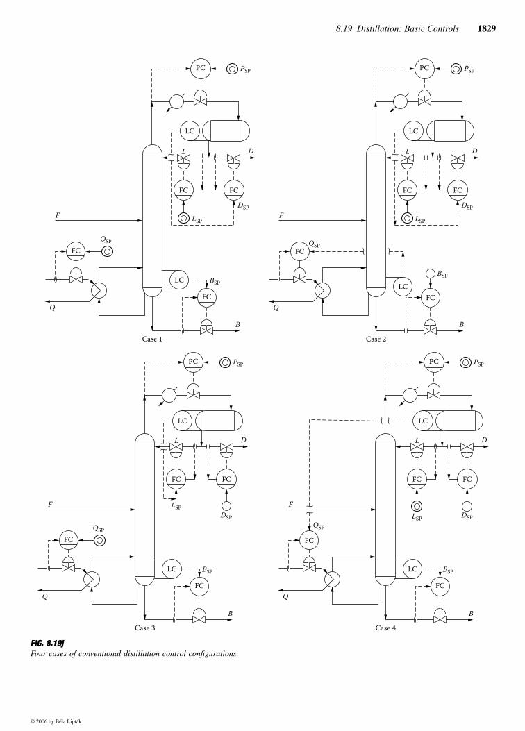
where [V/F] = the desired ratio of boil-up to feed.Figure 8.19j illustrates four of the most common basic
controls for the flows and levels of a two-product fractionator,where it is assumed that feed flow and tower pressure areheld constant. A different set of the above control equationsfor controlling internal product flow rates will apply, depend-ing upon the configuration of instrumentation used.
Scaling
The form of the control system equations influences the com-puting functions required. Boolean operands, such as highand low selectors, and dynamic functions, such as dead times,lead, and lag function, are also used. Most process automationsystems have these basic computing function blocks. Imple-mentation in a distributed control system (DCS), programmable
Degree of Separation =××
ln(% % )
(% %eD B
D
LK HK
HK LKKB)
Orientation of Separation =%
%
HK
LKD
B
Sy xx y
= −−
( )( )11
V F a by xx y
= + −−
( )( )11
© 2006 by Béla Lipták
8.19 Distillation: Basic Controls 1829
FIG. 8.19jFour cases of conventional distillation control configurations.
LC
FC FC
PC
LC
FC
FC
PSP
D
DSP
LSP LSP
LSP
QSP
BSP
L
F
Q
B
Case 1
LC
FC FC
PC
LC
FC
FC
PSP
D
DSP
QSP
BSP
L
F
Q
B
Case 3
LC
FC FC
PC
LC
FC
FC
PSP
D
DSP
QSP
BSP
L
F
Q
B
Case 2
LSP
LC
FC FC
PC
LC
FC
FC
PSP
D
DSP
QSP
BSP
L
F
Q
B
Case 4
© 2006 by Béla Lipták
1830 Control and Optimization of Unit Operations
logic controller (PLC), or multivariable digital controllers isvendor-specific.
The terms of the equations are sometimes scaled becausemost analog instruments and some PAS systems act on nor-malized numbers (0–100%) rather than on actual processvalues. With digital instrumentation and today’s process auto-mation systems, those occurrences are rare. The calculationsbecome easier for those systems operating in engineeringunits.
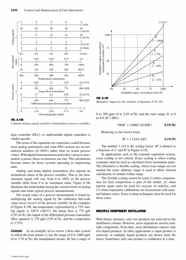
Analog, and many digital, transmitters also operate onnormalized values of the process variables. That is, the mea-surement signal will vary from 0 to 100% as the processvariable shifts from 0 to its maximum value. Figure 8.19killustrates the relationship among the various forms of analogsignals and some typical process measurements.
The actual value of a process measurement is found bymultiplying the analog signal by the calibrated full-scalevalue (meter factor) of the process variable. In the examplesof Figure 8.19k, the temperature, represented by a 75% ana-log signal, is 320°F (160°C), the linear flow is 775 gph(2.93 m3/h), the output of the differential pressure transmitter(flow squared) is 779 gph (2.95 m3/h), and the compositionis 3.75%.
Example As an example, let us review a flow ratio systemin which the load stream, L, has the range of 0 to 1000 gpm(0 to 3.79 m3/h); the manipulated stream, M, has a range of
0 to 700 gpm (0 to 2.65 m3/h); and the ratio range, R, is 0to 0.8 (R = M/L).
700M ′ = (1000L′)(0.80R′) 8.19(38)
Reducing to the lowest form,
M′ = 1.143(L′)(R′) 8.19(39)
The number 1.143 is the scaling factor. M′ is plotted asa function of L′ and R′ in Figure 8.19l.
In applications such as the constant separation system,exact scaling is not critical. Exact scaling is when scalingconstants must be used as calculated from instrument spans.The alternative is flexible scaling, where exact ranges are notneeded but some arbitrary range is used to allow internalcalculations to remain within range.
The flexible scaling cannot be used (1) when compensa-tion for feed composition is part of the model, (2) whennarrow spans must be used for reasons of stability, and(3) when transmitter calibrations are inconsistent with mate-rial balance ratios. Exact scaling techniques must be used forthese cases.
MULTIPLE COMPONENT DISTILLATION
With binary mixtures, only two products are removed in thedistillation column. However, most separations involve mul-tiple components. Even then, most distillations remove onlytwo liquid products. In other applications a vapor product isremoved, or multiple liquid products are drawn from thetower. Sometimes only one product is withdrawn at a time.
FIG. 8.19k Common analog signals and their relationship to process variables.
1 2 3 4 5
1 2 3 4 5
10 20 30 40 50
4 208 12 16
3
0.2 0.4 0.6 0.8 1.0
6 9 12 15
Volts
mA dc
mA dc
mA dc
PSIG
bar
0 0.25 0.50 0.75 1.0
0 25% 50% 75% 100%
An
alo
g s
ign
als
No
rmal
ized
valu
es
93 116 138 160 182°C
200 240 280 320 360°F
0 0.85 1.7 2.93 3.4
0 225 450 775 900
0 1.7 2.4 2.95 3.4
0 450 636 779 900
0 1.25 2.50 3.75 5.0
Pro
cess
val
ues
Temperature transmitter
Linear flow transmitter
Differential pressure flow transmitter
Chromatograph output
m3/h
GPH
m3/h
GPH
%
FIG. 8.19l Multiplier output for the solution of Equation 8.19 (39).
0% 25 50 75 100%
100%
75
50
25Mu
ltip
lier
ou
tpu
t, n
orm
aliz
ed
man
ipu
late
d v
aria
ble
(M
′)
Multiplier input, normalized ratio (R′)
L′ = 25%
L′ = 50%
L′ = 75%
L′ = 100%
1.143 L′
© 2006 by Béla Lipták

8.19 Distillation: Basic Controls 1831
Columns with Sidedraw
Having a sidestream product in addition to the overhead andbottom products adds a degree of freedom to a control sys-tem. The source of this extra degree of freedom can be seenfrom the overall material balance equation:
F = D + C + B 8.19(40)
where C is the sidestream flow rate. Two of the productstreams can be manipulated for control purposes, and thematerial balance can still be closed by the third productstream.
The presence of this added degree of freedom makes thecareful analysis of the process even more essential to avoidmismatching of the manipulated and controlled variables. Asin the case of the previously discussed columns, the devel-opment of a control system for sidedraw applications alsoinvolves developing the process model and determining therelationship among the several controlled and manipulatedvariables.
In this case, for a constant feed rate and column pressure,five degrees of freedom exist: three composition specificationsand two levels that can manipulate three product flows, andtwo heat balances (V and L). Several possible combinationsof variables are available and should be explored.
The possible combinations of manipulated variables forthe column in which the bottom composition and the side-stream composition must be controlled are
Distillate and sidestream flowsDistillate and bottom flowsDistillate flow and heat inputSidestream and bottom flowsSidestream flow and heat inputBottom flow and heat input
Similarly, the possible combinations of manipulated vari-ables for the column in which the distillate composition andthe sidestream composition must be controlled are:
Distillate and sidestream flowsDistillate and bottom flowsDistillate flow and heat inputSidestream and bottom flowsSidestream flow and refluxBottom flow and reflux
The equations are
8.19(41)
8.19(42)
The symbols z1, y1, and c1 refer to the concentrations inthe feed, distillate, and sidestream of the component undercontrol in the sidestream. The concentrations of the key com-ponent in the bottom are respectively expressed by z2, x2, andc2 for the feed, the bottoms, and the sidestream.
The resulting control system is shown in Figure 8.19m.Note that in this configuration the ratio of heat input to feed(and, therefore, boil-up to feed) is held constant. Separatedynamic elements are used for the distillate loop and for theheat input and sidestream loops.
Multiproduct Fractionators
Multiproduct fractionators are most common in the refiningindustry where multicomponent streams are separated intomany fractions. Examples of multiproduct fractionators arecrude towers, vacuum towers, and fluidized catalytic crackingunit (FCCU) main fractionators.
Product quality controls are used to adjust local columntemperatures and sidedraw flow rates to control distillateproperties related to the product specifications. An exampleis true boiling point (TBP) cut points. TBP cut points approx-imate the composition of a hydrocarbon mixture and arenumerically similar to the American Society for Testing and
D Fz c
y c=
−−
1 1
1 1
C Fz x
c x=
−−
2 2
2 2
FIG. 8.19mControl of composition in two product streams with a sidedraw.
LTLIC
FIC
FT FT
FYX
FIC
D, y1, y2
C, c1, c2
B, x1, x2
V
L
AT
FT
ARC
FT
FIC
LT
LIC
ATARCFYX
FT
RICRatio
controller
F, z1, z2
FY
FYDynamics
Dynamics
© 2006 by Béla Lipták

1832 Control and Optimization of Unit Operations
Materials’ (ASTM’s) 95%. The ASTM laboratory distillateevaluation method is the standard used in the petroleum refin-ing industry for determining the value (composition) of thedistillation products.
A computer is required to calculate the product boilingpoint specification, such as 95% boiling point or TBP cutpoint on the basis of local temperature, pressure, steam flow,and reflux data. Local reflux is derived from internal liquidand vapor flows, as discussed previously, and the remainingvariables are measured.
Boiling point analyzers can be used to provide the mea-surement signals. If there is no analyzer, the calculated boil-ing points can be used by themselves, or if there is one, theycan be used as a fast inner loop with analyzer trim. Becauseof the volume of liquid/vapor loads within most multiproductfractionators, the manipulated variables that provide thegreatest sensitivity and the quickest response are generallythe product flows.
Adjustment of reflux flows, as shown in Figure 8.19n,is an example of a heat balance control. The goal is tomaximize heat exchange to feed, subject to certain limits8
(limits and constraints are discussed as part of the subjectof the optimization of distillation towers in Section 8.21).The task of maximizing the heating of the feed often sim-plifies to recovering heat at the highest possible tempera-ture, which means recovering it as low as possible in thecolumn.
Superfractionators
The term superfractionator is applied to towers that are phys-ically large. These distillation units separate streams havingtheir light and heavy key relative volatilities quite close toeach other. Included in this classification are deisobutanizers,which separate isobutane from normal butane; propylenesplitters, which separate propane from propylene; ethylben-zene towers, which separate ethylbenzene from xylene; andxylene splitters, which separate para- and ortho-xylene frommeta-xylene.
Sometimes, the number of trays and subsequent heightmake it necessary to physically divide these towers into twoor even three sections. Superfractionators have tremendousinternal vapor-liquid rates in order to achieve the separation.Reflux-to-distillate ratios are very high, as are vapor-to-bottomsratios.
A large pressure drop through the tower also exists. Longdead times and lag times are experienced before any responseis seen to feed rate or reflux changes. Generally, distillatecompositions of superfractionators have to be controlled withmaterial balance equations due to the lack of sensitivity ofresponse.
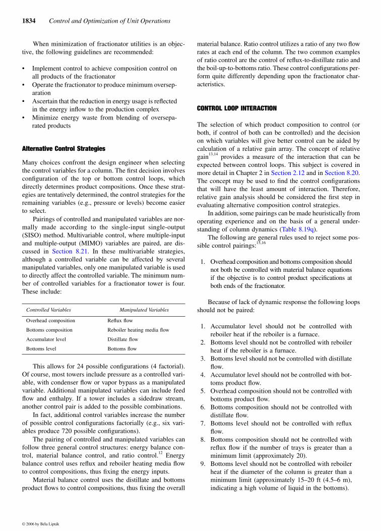
Batch Distillation
In batch distillation (see Figure 8.19o), an initial charge ofliquid is fed to a vessel, and the distillation process is initiated
FIG. 8.19nControl of product flows and pump-around refluxes.
Heat
balance
logicBoiling
point
calculation
Accumulator
FRC FTQ
FRC FTQ
PRC
PT
SP
FRCFT
FRCFT
FRC FT
FRCFT
D
DL
C
C
B
F
Mai
n f
ract
ion
atio
n
© 2006 by Béla Lipták
8.19 Distillation: Basic Controls 1833
by turning on the heating and cooling systems. During thedistillation process, the initial charge in the vessel continuallydepletes while building up the overhead product in the dis-tillate receiver.
Batch distillations are more common in smaller, multi-product plants where the various products can only be man-ufactured at different times, and where a number of differentmixtures may be handled in the same equipment.Equation 8.19(43) is the basic equation that describes thisoperation:
W = Wi − Dt 8.19(43)
whereW = amount remaining in the bottomsWi = the initial charge
D = distillate ratet = time period of operation
The basic objective of the control system of this type ofseparation is to keep the composition of the distillate con-stant. Other goals include keeping the distillate flow constantor maximizing the total distillate production. The main goalof a batch distillation is to produce a product of specifiedcomposition at minimum cost. This often means that operat-ing time must be reduced to some minimum while productpurity or recovery is maintained within acceptable limits.
If product removal is too fast, separation and the quantityof the product are reduced. Conversely, if the product iswithdrawn to maintain separation, its withdrawal rate isreduced and operating time is increased. However, the setpoint to a composition controller can be programmed so thatthe average composition of the product will still be withinspecifications while withdrawal rate is maximized.9
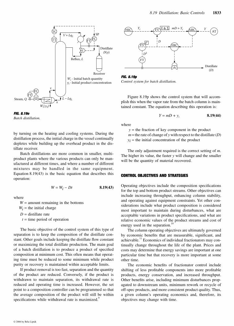
Figure 8.19p shows the control system that will accom-plish this when the vapor rate from the batch column is main-tained constant. The equation describing this operation is:
Y = mD + yi 8.19(44)
wherey = the fraction of key component in the productm = the rate of change of y with respect to the distillate (D)yi = the initial concentration of the product
The only adjustment required is the correct setting of m.The higher its value, the faster y will change and the smallerwill be the quantity of material recovered.
CONTROL OBJECTIVES AND STRATEGIES
Operating objectives include the composition specificationsfor the top and bottom product streams. Other objectives caninclude increasing throughput, enhancing column stability,and operating against equipment constraints. Yet other con-siderations include what product composition is consideredmost important to maintain during disturbances, what areacceptable variations in product specifications, and what arerelative economic values of the product streams and cost ofenergy used in the separation.10
The column operating objectives are ultimately governedby economic benefits that are measurable, significant, andachievable.11 Economics of individual fractionators may con-tinually change throughout the life of the plant. Prices andcosts may determine that energy savings are important at oneparticular time but that recovery is more important at someother time.
The economic benefits of fractionator control includeshifting of less profitable components into more profitableproducts, energy conservation, and increased throughput.Other benefits arise, including minimum disturbances prop-agated to downstream units, minimum rework or recycle ofoff-spec products, and more consistent product quality. Thus,a given column’s operating economics and, therefore, itsobjectives may change with time.
FIG. 8.19oBatch distillation.
Distillate
D(y)
Receiver
SP
FT
TC
TT FC
Reflux, L
V + LqL
Wi - Initial batch quantity
yi - Initial product concentration
FT
Steam, Q
Wi( y2)
v
xL − LqL
FC
FIG. 8.19pControl system for batch distillation.
X & ΣHIC ARC AT
YYi mD + Yi
DFY
FT
D2
FRC
Distillate
(D)
FY
© 2006 by Béla Lipták
1834 Control and Optimization of Unit Operations
When minimization of fractionator utilities is an objec-tive, the following guidelines are recommended:
• Implement control to achieve composition control onall products of the fractionator
• Operate the fractionator to produce minimum oversep-aration
• Ascertain that the reduction in energy usage is reflectedin the energy inflow to the production complex
• Minimize energy waste from blending of oversepa-rated products
Alternative Control Strategies
Many choices confront the design engineer when selectingthe control variables for a column. The first decision involvesconfiguration of the top or bottom control loops, whichdirectly determines product compositions. Once these strat-egies are tentatively determined, the control strategies for theremaining variables (e.g., pressure or levels) become easierto select.
Pairings of controlled and manipulated variables are nor-mally made according to the single-input single-output(SISO) method. Multivariable control, where multiple-inputand multiple-output (MIMO) variables are paired, are dis-cussed in Section 8.21. In these multivariable strategies,although a controlled variable can be affected by severalmanipulated variables, only one manipulated variable is usedto directly affect the controlled variable. The minimum num-ber of controlled variables for a fractionator tower is four.These include:
This allows for 24 possible configurations (4 factorial).Of course, most towers include pressure as a controlled vari-able, with condenser flow or vapor bypass as a manipulatedvariable. Additional manipulated variables can include feedflow and enthalpy. If a tower includes a sidedraw stream,another control pair is added to the possible combinations.
In fact, additional control variables increase the numberof possible control configurations factorially (e.g., six vari-ables produce 720 possible configurations).
The pairing of controlled and manipulated variables canfollow three general control structures: energy balance con-trol, material balance control, and ratio control.12 Energybalance control uses reflux and reboiler heating media flowto control compositions, thus fixing the energy inputs.
Material balance control uses the distillate and bottomsproduct flows to control compositions, thus fixing the overall
material balance. Ratio control utilizes a ratio of any two flowrates at each end of the column. The two common examplesof ratio control are the control of reflux-to-distillate ratio andthe boil-up-to-bottoms ratio. These control configurations per-form quite differently depending upon the fractionator char-acteristics.
CONTROL LOOP INTERACTION
The selection of which product composition to control (orboth, if control of both can be controlled) and the decisionon which variables will give better control can be aided bycalculation of a relative gain array. The concept of relativegain13,14 provides a measure of the interaction that can beexpected between control loops. This subject is covered inmore detail in Chapter 2 in Section 2.12 and in Section 8.20.The concept may be used to find the control configurationsthat will have the least amount of interaction. Therefore,relative gain analysis should be considered the first step inevaluating alternative composition control strategies.
In addition, some pairings can be made heuristically fromoperating experience and on the basis of a general under-
The following are general rules used to reject some pos-sible control pairings:15,16
1. Overhead composition and bottoms composition shouldnot both be controlled with material balance equationsif the objective is to control product specifications atboth ends of the fractionator.
Because of lack of dynamic response the following loopsshould not be paired:
1. Accumulator level should not be controlled withreboiler heat if the reboiler is a furnace.
2. Bottoms level should not be controlled with reboilerheat if the reboiler is a furnace.
3. Bottoms level should not be controlled with distillateflow.
4. Accumulator level should not be controlled with bot-toms product flow.
5. Overhead composition should not be controlled withbottoms product flow.
6. Bottoms composition should not be controlled withdistillate flow.
7. Bottoms level should not be controlled with refluxflow.
8. Bottoms composition should not be controlled withreflux flow if the number of trays is greater than aminimum limit (approximately 20).
9. Bottoms level should not be controlled with reboilerheat if the diameter of the column is greater than aminimum limit (approximately 15–20 ft (4.5–6 m),indicating a high volume of liquid in the bottoms).
Controlled Variables Manipulated Variables
Overhead composition Reflux flow
Bottoms composition Reboiler heating media flow
Accumulator level Distillate flow
Bottoms level Bottoms flow
© 2006 by Béla Lipták
standing of column dynamics (Table 8.19q).

8.19 Distillation: Basic Controls 1835
10. Accumulator level should not be controlled withreboiler heat if the control objective is to maintainoverhead product specification and the V/B ratio isless than a minimum limit (approximately 3).
Because of lack of sensitivity, these loops should not bepaired:
1. Overhead composition should not be controlled withreflux flow if the reflux ratio (L/D) is less than a mini-mum value (approximately 6).
2. Accumulator level should not be controlled with dis-tillate flow if the reflux ratio (L/D) is less than a max-imum value (approximately 6).
3. Accumulator level should not be controlled with refluxflow if the reflux ratio (L/D) is less than a maximumvalue (approximately 0.5).
4. Bottoms composition should not be controlled withsidedraw flow if the sidedraw is a vapor phase.
5. Overhead composition should not be controlled withsidedraw flow if the sidedraw is a liquid phase.
6. Bottoms composition should not be controlled withsidedraw flow if the sidedraw is a liquid phase and thesidedraw tray number is greater than a minimum num-ber (approximately 20).
7. Sidedraw composition should not be controlled withreflux or distillate flow if the difference between the totalnumber of trays and the number of the sidestream trayis greater than a minimum value (approximately 20).
8. Bottoms level should not be controlled with sidedrawflow if the difference between the bottoms and the
number of the sidestream tray is greater than a mini-mum value (approximately 100).
9. Bottoms level should not be controlled with bottomsflow if the V/B ratio is greater than a minimum limit(approximately 3).
Choices for controlling product compositions include(1) controlling top or bottom composition only (generallysuitable for constant separation conditions, where specifica-tions for one product are loose or where effective feedforward/feedback systems can be designed to compensate for loadchanges) and (2) controlling of both product compositions(minimizes energy use and provides tight specification top andbottom products for columns in which the problems of inter-action are small).
These choices can be broken down further into consid-erations such as manipulation of distillate-boil-up, DV con-figuration (generally suitable for high reflux columns) ormanipulation of reflux-boil-up, LV configuration (generallysuitable for low reflux columns), and so forth.
Further considerations include the use of decoupling con-trol schemes (can present practical problems, such as insensi-tive control, operating problems, and high sensitivity to errors)and the use of temperature measurements to infer compositionor analyzers to measure composition directly (generally aneconomic decision based on how well a temperature-sensitivecontrol point can be determined and the costs of analyzerhardware and maintenance). These choices are based on oper-ating objectives of the column, expected disturbance variables,and the degree of control loop interaction.
TABLE 8.19q Dynamic Response and Sensitivity Limitations on the Pairing of Distillation Control Variables4
(Both compositions should not be controlled by material balance (B,D) if both specifications are important)
Distillate Flow(D)
Bottoms Product Flow(B)
Vaporization Rate (V) orHeat Input at Reboiler (O)
Reflux Flow Rate(L)
Composition of Overhead Product (ACy) OK if L /D � 6Note 3
Notes 1 and 2 Note 2
Composition of Bottoms Product (ACx) Note 3 Notes 1 and 2 OK if trays � 20
Accumulator Level (LCa) OK if L/D � 6 Not good with furnaceOK if V/B � 3
OK if L/D � 0.5
Bottoms Level (LCb) OK if V/B � 3 Not good if furnace is usedOK if diameter at bottom � 20 ft
Notes: 1. Control that concentration (x or y) which has the shorter residence time by throttling vapor flow (v).2. More pure product should control separation (energy).3. Less pure product should control material balance.4. When controlling both x and y, the only choices for possible pairings are:
a. Control y by D and x by V. b. Control y by D and x by L. c. Control y by L and x by V. d. Control y by B and x by L.
Of these, choice d is not recommended because a y/B combination is not responsive dynamically.
Controlled Variable
Manipulated Variable
© 2006 by Béla Lipták
1836 Control and Optimization of Unit Operations
PRODUCT QUALITY CONTROL
Conceptually, product control is a problem of making preciseadjustments to the rate of heat addition and the rate of heatremoval from the tower. Heat removal determines the internalreflux flow rate, and the internal reflux as measured on thetop tray is a direct reflection of the composition of the dis-tillate. Heat added determines the internal vapor rate. Theseinternal vapor and liquid flow rates determine the circulationrate, which in turn determines the degree of separationbetween two key components.
Once interaction of the various variable pairings has beenestablished, and the column’s operating objectives and dis-turbance variables are considered, the primary compositioncontrol loops of the column can be selected. Measurementof these control variables can be either direct or inferred.
Inferring Composition from Temperature
If the cost of on-line analyzer hardware and maintenance isprohibitive, or if backup is desired in case of analyzer failureor maintenance, and because the results of laboratory analysistake too long to be usable for effective control, temperaturemeasurement often can be used to infer composition.
Because distillation separates materials according to theirdifference in vapor pressures, and because vapor pressure is atemperature-controlled function, temperature measurement hashistorically been used to indicate composition. This presumesthat the column pressure remains constant, or that the temper-ature measurement is compensated for pressure changes, andthat feed composition is constant. Then, any change in compo-sition within a column will be detected as a temperature change.
The best point to locate the temperature sensor cannot beestablished from generalizations. The important considerationis to measure the temperature on a tray that strongly reflectsthe changes in composition. When composition of the bottomproduct is important, it is desirable to maintain a constant tem-perature in the lower section. This can be done by letting thetemperature measurement manipulate the reboiler steam supplyby resetting the steam flow controller set point (Figure 8.19r).
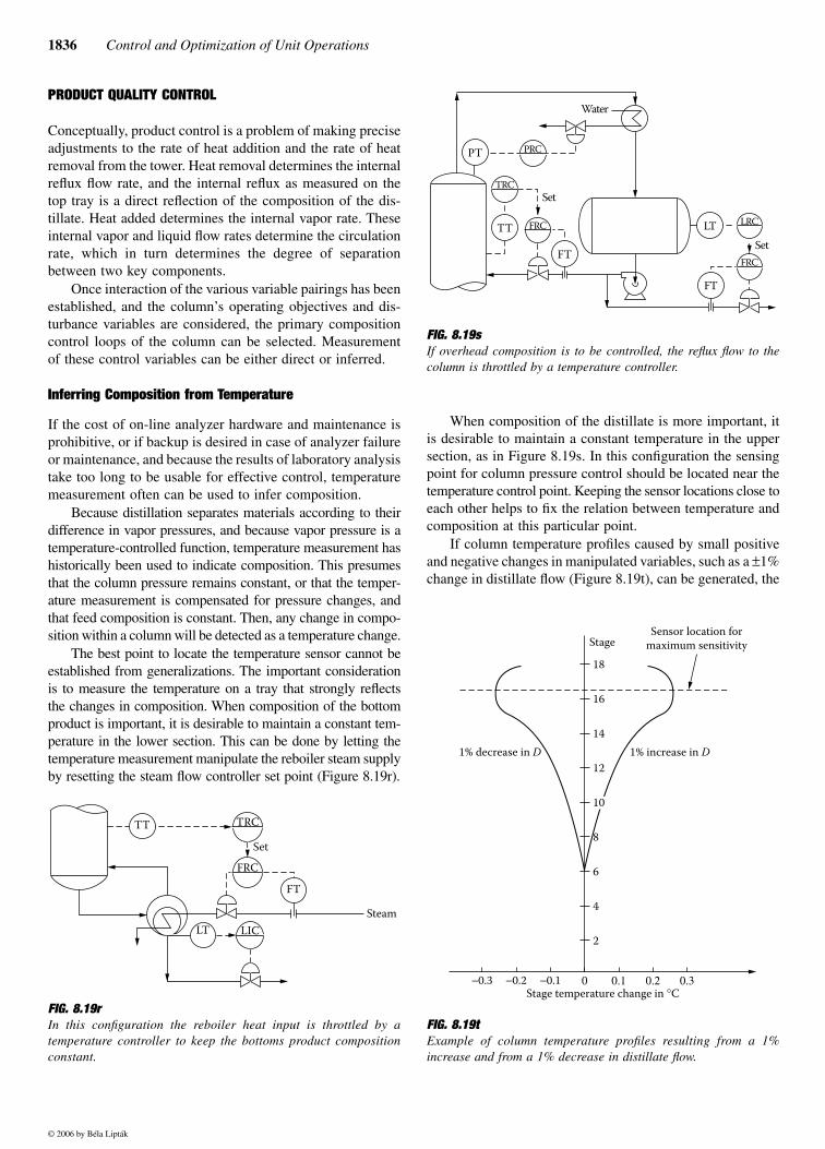
When composition of the distillate is more important, itis desirable to maintain a constant temperature in the uppersection, as in Figure 8.19s. In this configuration the sensingpoint for column pressure control should be located near thetemperature control point. Keeping the sensor locations close toeach other helps to fix the relation between temperature andcomposition at this particular point.
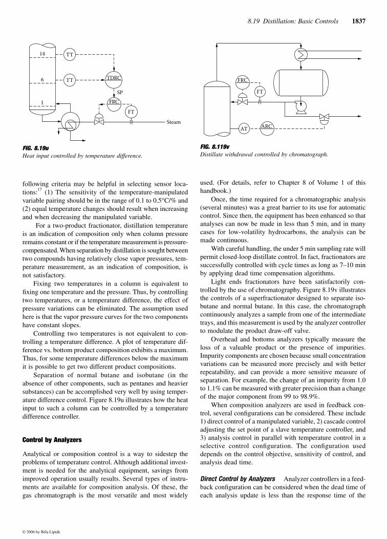
If column temperature profiles caused by small positiveand negative changes in manipulated variables, such as a ±1%change in distillate flow (Figure 8.19t), can be generated, the
FIG. 8.19rIn this configuration the reboiler heat input is throttled by atemperature controller to keep the bottoms product compositionconstant.
TT
FT
TRC
FRC
LT LIC
Set
Steam
FIG. 8.19sIf overhead composition is to be controlled, the reflux flow to thecolumn is throttled by a temperature controller.
FIG. 8.19tExample of column temperature profiles resulting from a 1%increase and from a 1% decrease in distillate flow.
PRC
LRC
TRC
FRC
PT
TT
Water
LT
FRC
FT
Set
Set
FT
18
16
14
12
10
8
6
4
2
StageSensor location for
maximum sensitivity
−0.3 −0.2 −0.1 0 0.1 0.2 0.3Stage temperature change in °C
1% decrease in D 1% increase in D
© 2006 by Béla Lipták
8.19 Distillation: Basic Controls 1837
following criteria may be helpful in selecting sensor loca-tions:17 (1) The sensitivity of the temperature-manipulatedvariable pairing should be in the range of 0.1 to 0.5°C/% and(2) equal temperature changes should result when increasingand when decreasing the manipulated variable.
For a two-product fractionator, distillation temperatureis an indication of composition only when column pressureremains constant or if the temperature measurement is pressure-compensated. When separation by distillation is sought betweentwo compounds having relatively close vapor pressures, tem-perature measurement, as an indication of composition, isnot satisfactory.
Fixing two temperatures in a column is equivalent tofixing one temperature and the pressure. Thus, by controllingtwo temperatures, or a temperature difference, the effect ofpressure variations can be eliminated. The assumption usedhere is that the vapor pressure curves for the two componentshave constant slopes.
Controlling two temperatures is not equivalent to con-trolling a temperature difference. A plot of temperature dif-ference vs. bottom product composition exhibits a maximum.Thus, for some temperature differences below the maximumit is possible to get two different product compositions.
Separation of normal butane and isobutane (in theabsence of other components, such as pentanes and heaviersubstances) can be accomplished very well by using temper-ature difference control. Figure 8.19u illustrates how the heatinput to such a column can be controlled by a temperaturedifference controller.
Control by Analyzers
Analytical or composition control is a way to sidestep theproblems of temperature control. Although additional invest-ment is needed for the analytical equipment, savings fromimproved operation usually results. Several types of instru-ments are available for composition analysis. Of these, thegas chromatograph is the most versatile and most widely
used. (For details, refer to Chapter 8 of Volume 1 of thishandbook.)
Once, the time required for a chromatographic analysis(several minutes) was a great barrier to its use for automaticcontrol. Since then, the equipment has been enhanced so thatanalyses can now be made in less than 5 min, and in manycases for low-volatility hydrocarbons, the analysis can bemade continuous.
With careful handling, the under 5 min sampling rate willpermit closed-loop distillate control. In fact, fractionators aresuccessfully controlled with cycle times as long as 7–10 minby applying dead time compensation algorithms.
Light ends fractionators have been satisfactorily con-trolled by the use of chromatography. Figure 8.19v illustratesthe controls of a superfractionator designed to separate iso-butane and normal butane. In this case, the chromatographcontinuously analyzes a sample from one of the intermediatetrays, and this measurement is used by the analyzer controllerto modulate the product draw-off valve.
Overhead and bottoms analyzers typically measure theloss of a valuable product or the presence of impurities.Impurity components are chosen because small concentrationvariations can be measured more precisely and with betterrepeatability, and can provide a more sensitive measure ofseparation. For example, the change of an impurity from 1.0to 1.1% can be measured with greater precision than a changeof the major component from 99 to 98.9%.
When composition analyzers are used in feedback con-trol, several configurations can be considered. These include1) direct control of a manipulated variable, 2) cascade controladjusting the set point of a slave temperature controller, and3) analysis control in parallel with temperature control in aselective control configuration. The configuration useddepends on the control objective, sensitivity of control, andanalysis dead time.
Direct Control by Analyzers Analyzer controllers in a feed-back configuration can be considered when the dead time ofeach analysis update is less than the response time of the
FIG. 8.19uHeat input controlled by temperature difference.
14
6
1
TDRC
FRC
SP
TT
TT
FT
Steam
FIG. 8.119vDistillate withdrawal controlled by chromatograph.
FRC
ARC
FT
AT
© 2006 by Béla Lipták
1838 Control and Optimization of Unit Operations
process. Because it is the control of the composition of theproduct, which is often the objective, direct control by ananalyzer controller would seem to be better than indirectcontrol by temperature.
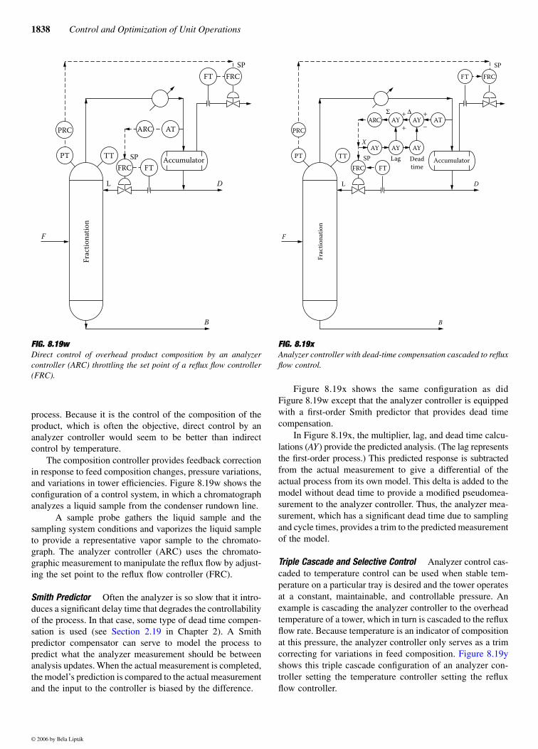
The composition controller provides feedback correctionin response to feed composition changes, pressure variations,and variations in tower efficiencies. Figure 8.19w shows theconfiguration of a control system, in which a chromatographanalyzes a liquid sample from the condenser rundown line.
A sample probe gathers the liquid sample and thesampling system conditions and vaporizes the liquid sampleto provide a representative vapor sample to the chromato-graph. The analyzer controller (ARC) uses the chromato-graphic measurement to manipulate the reflux flow by adjust-ing the set point to the reflux flow controller (FRC).
Smith Predictor Often the analyzer is so slow that it intro-duces a significant delay time that degrades the controllabilityof the process. In that case, some type of dead time compen-sation is used (see Section 2.19 in Chapter 2). A Smithpredictor compensator can serve to model the process topredict what the analyzer measurement should be betweenanalysis updates. When the actual measurement is completed,the model’s prediction is compared to the actual measurementand the input to the controller is biased by the difference.
Figure 8.19x shows the same configuration as didFigure 8.19w except that the analyzer controller is equippedwith a first-order Smith predictor that provides dead timecompensation.
In Figure 8.19x, the multiplier, lag, and dead time calcu-lations (AY) provide the predicted analysis. (The lag representsthe first-order process.) This predicted response is subtractedfrom the actual measurement to give a differential of theactual process from its own model. This delta is added to themodel without dead time to provide a modified pseudomea-surement to the analyzer controller. Thus, the analyzer mea-surement, which has a significant dead time due to samplingand cycle times, provides a trim to the predicted measurementof the model.
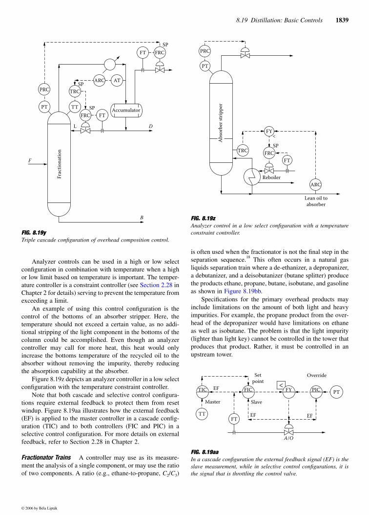
Triple Cascade and Selective Control Analyzer control cas-caded to temperature control can be used when stable tem-perature on a particular tray is desired and the tower operatesat a constant, maintainable, and controllable pressure. Anexample is cascading the analyzer controller to the overheadtemperature of a tower, which in turn is cascaded to the refluxflow rate. Because temperature is an indicator of compositionat this pressure, the analyzer controller only serves as a trimcorrecting for variations in feed composition. Figure 8.19yshows this triple cascade configuration of an analyzer con-troller setting the temperature controller setting the refluxflow controller.
FIG. 8.19w Direct control of overhead product composition by an analyzercontroller (ARC) throttling the set point of a reflux flow controller(FRC).
PRC
PT TT
FT
ARC AT
AccumulatorFRC
FRCFT
F
D
SP
L
SP
B
Fra
ctio
nat
ion
FIG. 8.19xAnalyzer controller with dead-time compensation cascaded to refluxflow control.
PRC
PT TT
L
ARC AY AY
AY AYAY
AccumulatorFRC
FRC
F
D
SP
SP
BF
ract
ion
atio
n
AT
X
Σ ∆+
+ −
+
Lag Dead
timeFT
FT
© 2006 by Béla Lipták
8.19 Distillation: Basic Controls 1839
Analyzer controls can be used in a high or low selectconfiguration in combination with temperature when a highor low limit based on temperature is important. The temper-ature controller is a constraint controller (see Section 2.28 inChapter 2 for details) serving to prevent the temperature fromexceeding a limit.
An example of using this control configuration is thecontrol of the bottoms of an absorber stripper. Here, thetemperature should not exceed a certain value, as no addi-tional stripping of the light component in the bottoms of thecolumn could be accomplished. Even though an analyzercontroller may call for more heat, this heat would onlyincrease the bottoms temperature of the recycled oil to theabsorber without removing the impurity, thereby reducingthe absorption capability at the absorber.
Figure 8.19z depicts an analyzer controller in a low selectconfiguration with the temperature constraint controller.
Note that both cascade and selective control configura-tions require external feedback to protect them from resetwindup. Figure 8.19aa illustrates how the external feedback(EF) is applied to the master controller in a cascade config-uration (TIC) and to both controllers (FIC and PIC) in aselective control configuration. For more details on externalfeedback, refer to Section 2.28 in Chapter 2.
Fractionator Trains A controller may use as its measure-ment the analysis of a single component, or may use the ratioof two components. A ratio (e.g., ethane-to-propane, C2/C3)
is often used when the fractionator is not the final step in theseparation sequence.18 This often occurs in a natural gasliquids separation train where a de-ethanizer, a depropanizer,a debutanizer, and a deisobutanizer (butane splitter) producethe products ethane, propane, butane, isobutane, and gasoline
Specifications for the primary overhead products mayinclude limitations on the amount of both light and heavyimpurities. For example, the propane product from the over-head of the depropanizer would have limitations on ethaneas well as isobutane. The problem is that the light impurity(lighter than light key) cannot be controlled in the tower thatproduces that product. Rather, it must be controlled in anupstream tower.
FIG. 8.19yTriple cascade configuration of overhead composition control.
PRC
PT TT
FT
ARC AT
AccumulatorFRC
FRCFT
F
D
SP
L
SP
B
Fra
ctio
nat
ion
TRC
SP
FIG. 8.19z Analyzer control in a low select configuration with a temperatureconstraint controller.
FIG. 8.19aaIn a cascade configuration the external feedback signal (EF) is theslave measurement, while in selective control configurations, it isthe signal that is throttling the control valve.
PRC
PT
Ab
sorb
er s
trip
per
ARC
TRCFRC
FY
FT
SP
Reboiler
<
Lean oil to
absorber
<TIC FIC FY PTPIC
Master
FT
EF
Set
point
TT
Slave
EF
Override
EF
A/O
© 2006 by Béla Lipták
as shown in Figure 8.19bb.
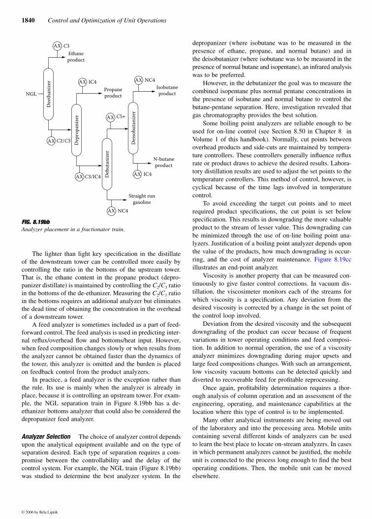
1840 Control and Optimization of Unit Operations
The lighter than light key specification in the distillateof the downstream tower can be controlled more easily bycontrolling the ratio in the bottoms of the upstream tower.That is, the ethane content in the propane product (depro-panizer distillate) is maintained by controlling the C2/C3 ratioin the bottoms of the de-ethanizer. Measuring the C2/C3 ratioin the bottoms requires an additional analyzer but eliminatesthe dead time of obtaining the concentration in the overheadof a downstream tower.
A feed analyzer is sometimes included as a part of feed-forward control. The feed analysis is used in predicting inter-nal reflux/overhead flow and bottoms/heat input. However,when feed composition changes slowly or when results fromthe analyzer cannot be obtained faster than the dynamics ofthe tower, this analyzer is omitted and the burden is placedon feedback control from the product analyzers.
In practice, a feed analyzer is the exception rather thanthe rule. Its use is mainly when the analyzer is already inplace, because it is controlling an upstream tower. For exam-ple, the NGL separation train in Figure 8.19bb has a de-ethanizer bottoms analyzer that could also be considered thedepropanizer feed analyzer.
Analyzer Selection The choice of analyzer control dependsupon the analytical equipment available and on the type ofseparation desired. Each type of separation requires a com-promise between the controllability and the delay of thecontrol system. For example, the NGL train (Figure 8.19bb)was studied to determine the best analyzer system. In the
depropanizer (where isobutane was to be measured in thepresence of ethane, propane, and normal butane) and inthe deisobutanizer (where isobutane was to be measured in thepresence of normal butane and isopentane), an infrared analysiswas to be preferred.
However, in the debutanizer the goal was to measure thecombined isopentane plus normal pentane concentrations inthe presence of isobutane and normal butane to control thebutane-pentane separation. Here, investigation revealed thatgas chromatography provides the best solution.
Some boiling point analyzers are reliable enough to beused for on-line control (see Section 8.50 in Chapter 8 inVolume 1 of this handbook). Normally, cut points betweenoverhead products and side-cuts are maintained by tempera-ture controllers. These controllers generally influence refluxrate or product draws to achieve the desired results. Labora-tory distillation results are used to adjust the set points to thetemperature controllers. This method of control, however, iscyclical because of the time lags involved in temperaturecontrol.
To avoid exceeding the target cut points and to meetrequired product specifications, the cut point is set belowspecification. This results in downgrading the more valuableproduct to the stream of lesser value. This downgrading canbe minimized through the use of on-line boiling point ana-lyzers. Justification of a boiling point analyzer depends uponthe value of the products, how much downgrading is occur-ring, and the cost of analyzer maintenance. Figure 8.19ccillustrates an end-point analyzer.
Viscosity is another property that can be measured con-tinuously to give faster control corrections. In vacuum dis-tillation, the viscosimeter monitors each of the streams forwhich viscosity is a specification. Any deviation from thedesired viscosity is corrected by a change in the set point ofthe control loop involved.
Deviation from the desired viscosity and the subsequentdowngrading of the product can occur because of frequentvariations in tower operating conditions and feed composi-tion. In addition to normal operation, the use of a viscosityanalyzer minimizes downgrading during major upsets andlarge feed compositions changes. With such an arrangement,low viscosity vacuum bottoms can be detected quickly anddiverted to recoverable feed for profitable reprocessing.
Once again, profitability determination requires a thor-ough analysis of column operation and an assessment of theengineering, operating, and maintenance capabilities at thelocation where this type of control is to be implemented.
Many other analytical instruments are being moved outof the laboratory and into the processing area. Mobile unitscontaining several different kinds of analyzers can be usedto learn the best place to locate on-stream analyzers. In casesin which permanent analyzers cannot be justified, the mobileunit is connected to the process long enough to find the bestoperating conditions. Then, the mobile unit can be movedelsewhere.
FIG. 8.19bbAnalyzer placement in a fractionator train.
Dee
than
izer
Dep
rop
aniz
er
Deb
uta
niz
er
Dei
sob
uta
niz
er
Ethane
product
AX C3
AX IC4 AX NC4
AX C5+
AX
AX
AX
NGL
NC4
AX IC4
Straight run
gasoline
N-butane
product
C3/IC4
C2/C3
Propane
product
Isobutane
product
© 2006 by Béla Lipták
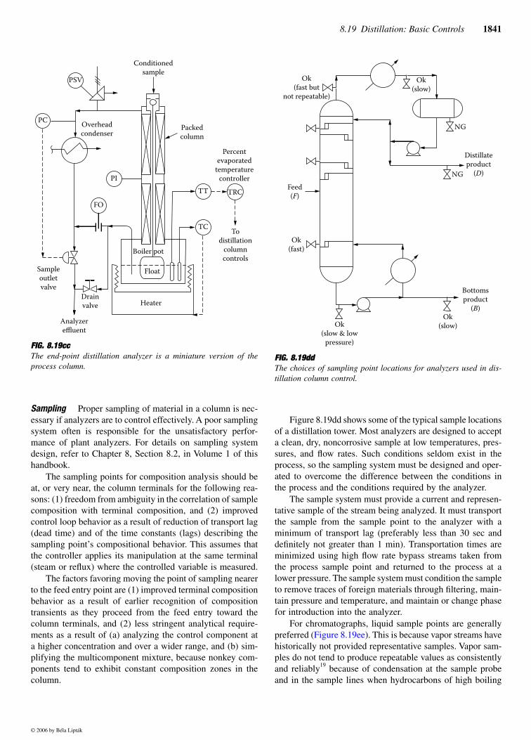
8.19 Distillation: Basic Controls 1841
Sampling Proper sampling of material in a column is nec-essary if analyzers are to control effectively. A poor samplingsystem often is responsible for the unsatisfactory perfor-mance of plant analyzers. For details on sampling systemdesign, refer to Chapter 8, Section 8.2, in Volume 1 of thishandbook.
The sampling points for composition analysis should beat, or very near, the column terminals for the following rea-sons: (1) freedom from ambiguity in the correlation of samplecomposition with terminal composition, and (2) improvedcontrol loop behavior as a result of reduction of transport lag(dead time) and of the time constants (lags) describing thesampling point’s compositional behavior. This assumes thatthe controller applies its manipulation at the same terminal(steam or reflux) where the controlled variable is measured.
The factors favoring moving the point of sampling nearerto the feed entry point are (1) improved terminal compositionbehavior as a result of earlier recognition of compositiontransients as they proceed from the feed entry toward thecolumn terminals, and (2) less stringent analytical require-ments as a result of (a) analyzing the control component ata higher concentration and over a wider range, and (b) sim-plifying the multicomponent mixture, because nonkey com-ponents tend to exhibit constant composition zones in thecolumn.
Figure 8.19dd shows some of the typical sample locationsof a distillation tower. Most analyzers are designed to accepta clean, dry, noncorrosive sample at low temperatures, pres-sures, and flow rates. Such conditions seldom exist in theprocess, so the sampling system must be designed and oper-ated to overcome the difference between the conditions inthe process and the conditions required by the analyzer.
The sample system must provide a current and represen-tative sample of the stream being analyzed. It must transportthe sample from the sample point to the analyzer with aminimum of transport lag (preferably less than 30 sec anddefinitely not greater than 1 min). Transportation times areminimized using high flow rate bypass streams taken fromthe process sample point and returned to the process at alower pressure. The sample system must condition the sampleto remove traces of foreign materials through filtering, main-tain pressure and temperature, and maintain or change phasefor introduction into the analyzer.
For chromatographs, liquid sample points are generallypreferred (Figure 8.19ee). This is because vapor streams havehistorically not provided representative samples. Vapor sam-ples do not tend to produce repeatable values as consistentlyand reliably19 because of condensation at the sample probeand in the sample lines when hydrocarbons of high boiling
FIG. 8.19ccThe end-point distillation analyzer is a miniature version of theprocess column.
Percent
evaporated
temperature
controller
Packed
column
TRC
To
distillation
column
controls
TC
TT
Boiler pot
Float
HeaterDrain
valve
Analyzer
effluent
Sample
outlet
valve
FO
PI
Overhead
condenser
PC
PSV
Conditioned
sample
FIG. 8.19ddThe choices of sampling point locations for analyzers used in dis-tillation column control.
Ok
(fast but
not repeatable)
Feed
(F)
Ok
(fast)
Ok
(slow)
NG
NG
Ok
(slow & low
pressure)
Ok
(slow)
Bottoms
product
(B)
Distillate
product
(D)
© 2006 by Béla Lipták
1842 Control and Optimization of Unit Operations
points are present in the sample. When the sample lines arelong, some separation between components can also occur.However, vapor samples can be used when warranted and ifthe proper care can be taken.
A satisfactory point for measuring bottoms product com-position is at the point of highest pressure. This approachwill ensure a representative sample and will provide the pres-sure drop to return the sample bypass. The point of highestpressure is generally immediately after the product pump.However, if liquid holdup in the reboiler and kettle is large, along lag is introduced, which slows the transient response ofthe measurement and control system. Alternative samplepoints such as a bottoms tray or seal pan may be used, butmay require extra expense for the sample system.
A satisfactory sample-point location for measuring thedistillate is the outlet liquid of the overhead vapor condenser.Sampling the overhead accumulator liquid after the reflux ordistillate pump should be avoided because of the tremendousprocess lag it introduces. Sampling the overhead vaporreduces the process lag of sampling after the condenser if arepeatable, representative sample can be obtained.
PRESSURE CONTROL
Most distillation columns are operated under constant pres-sure. However, floating-pressure operation can have advan-tages in many processes. One reason for the resistance to theuse of floating-pressure control is based on the fact thattemperature is sensitive to pressure changes, and therefore,
it requires pressure compensation if the pressure varies. Asanalyzers are increasingly replacing temperature-based con-trols, the argument favoring constant pressure operation isalso lessening. However, even when temperature control isused, the temperature measurements can be compensated forpressure variations.
The primary advantage of floating-pressure control is theability to operate at the minimum column pressure within theconstraints of the system. Lower pressure reduces the vola-tility of distillation components, thereby reducing the heatinput required to effect a given separation. Other advantagesinclude increased reboiler capacity and reduced reboiler foulingdue to lower tower temperatures.
In the following paragraphs, floating-pressure control strat-egies will be described for the following conditions: (1) liquiddistillate withdrawn when noncondensables are present,(2) vapor distillate withdrawn when noncondensables arepresent, and (3) liquid distillate withdrawn when the amountof noncondensables is negligible.
Liquid Distillate and Inerts
In some separation processes the problem of pressure controlis complicated by the presence of large percentages of inertgases. The noncondensables must be removed, or they willaccumulate and blanket off the condensing surface, therebycausing loss of column pressure control.
The simplest method of handling this problem is to bleedoff a fixed amount of gases and vapors to a lower pressure unit,such as to an absorption tower, if one is present in the system.
FIG. 8.19ee Sampling system for a liquid product in a refinery application.
SampleOut In
Cooling
inWater
out
Shut-off
valves
Flow
indicator
Self
cleaning
filter
Control
valve
Flow
indicator
with
needle
valve
FI
Check
valve
FI
Sample
cooler
Flow
indicatorFI
Pressure
gauge
PI
PI
FIT1
Temperature
gauge
Analyzer
Flow
indicator
with
needle
valve
Shut-off
valves
Calibration
sample
Lab sample
take off
Pressure
gaugeCheck
valve
Shut-off
valveTo
drain
Pressure
regulator
Coalescer
Pressure
relief valve
© 2006 by Béla Lipták
8.19 Distillation: Basic Controls 1843
If an absorber is not present, it is possible to install a ventcondenser to recover the condensable vapors from this purgestream. Often in refinery applications such noncondensables goto the fuel gas system or to flare.
It is recommended that the fixed continuous purge beused whenever economically possible; however, when this isnot permitted, it is possible to modulate the purge stream.This might be desirable when the amount of inerts is subjectto wide variations over time.
As the noncondensables build up in the condenser, thepressure controller will tend to open the control valve (PCV-1in Figure 8.19ff) to maintain the proper rate of condensation.The controller signal that is throttling PCV-1 could also be
used to start opening the purge control valve (VPCV-2), whenthe opening of PCV-1 reaches some preset limit. This can bedone by means of a calibrated valve positioner or by usinga valve position controller (VPC-2) in Figure 8.19ff.
Vapor Distillate and Inerts
In the case where the distillate is in the vapor phase and inertsare present, the overhead product is removed under pressurecontrol as shown in Part A of Figure 8.19gg. In this config-uration the system pressure will quickly respond to changesin the distillate vapor flow. In this control system a levelcontroller is installed on the overhead receiver to regulate thecooling water to the condenser, so that it will condense onlyenough condensate to provide the column with reflux.
This control system will operate properly only if thecondenser is designed to provide a short residence time forthe coolant, which will minimize the level control time lag.If this is not the case, the cooling water flow should bemaintained at a constant rate.
In this case (Part B in Figure 8.19gg), the level controllercan regulate the flow of condensate through a small vaporizerand mix it with the vapor from the pressure control valve.
If the cooling water has fouling tendencies, it is prefer-able to use the control system shown in Figure 8.19hh, wherea pressure controller regulates a vapor bypass around thecondenser.
Liquid Distillate with Negligible Inerts
In distillation processes where the distillate is in the liquidphase and the amount of inerts is negligible, the columnpressure is usually controlled by modulating the rate of con-densation in the condenser. The method of controlling the
FIG. 8.19ff Column pressure control with inerts present.
Partially
flooded
condenser
PTPRC
1
Vent
VPCV
2VPC
2PCV
1
LT LIC
FIG. 8.19gg Column pressure control when the distillate is in the vapor phase and contains inerts for variable (A) and constant condenser water flowconfigurations (B).
A. Variable water flow
Dry
condenser
PT
PRC
Water
LRC
ReceiverLT
Vapor (D)
B. Constant water flow
Dry
condenser
PT
PRC
LRCLT
Vapor
(D)
VaporizerWater
© 2006 by Béla Lipták
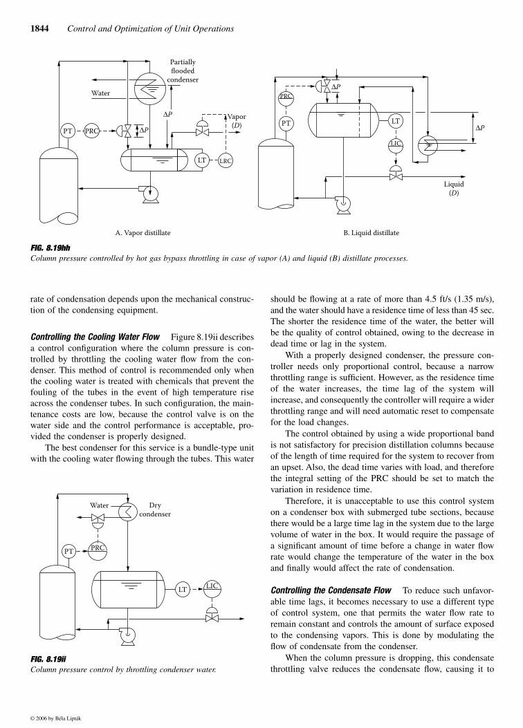
1844 Control and Optimization of Unit Operations
rate of condensation depends upon the mechanical construc-tion of the condensing equipment.
Controlling the Cooling Water Flow Figure 8.19ii describesa control configuration where the column pressure is con-trolled by throttling the cooling water flow from the con-denser. This method of control is recommended only whenthe cooling water is treated with chemicals that prevent thefouling of the tubes in the event of high temperature riseacross the condenser tubes. In such configuration, the main-tenance costs are low, because the control valve is on thewater side and the control performance is acceptable, pro-vided the condenser is properly designed.
The best condenser for this service is a bundle-type unitwith the cooling water flowing through the tubes. This water
should be flowing at a rate of more than 4.5 ft/s (1.35 m/s),and the water should have a residence time of less than 45 sec.The shorter the residence time of the water, the better willbe the quality of control obtained, owing to the decrease indead time or lag in the system.
With a properly designed condenser, the pressure con-troller needs only proportional control, because a narrowthrottling range is sufficient. However, as the residence timeof the water increases, the time lag of the system willincrease, and consequently the controller will require a widerthrottling range and will need automatic reset to compensatefor the load changes.
The control obtained by using a wide proportional bandis not satisfactory for precision distillation columns becauseof the length of time required for the system to recover froman upset. Also, the dead time varies with load, and thereforethe integral setting of the PRC should be set to match thevariation in residence time.
Therefore, it is unacceptable to use this control systemon a condenser box with submerged tube sections, becausethere would be a large time lag in the system due to the largevolume of water in the box. It would require the passage ofa significant amount of time before a change in water flowrate would change the temperature of the water in the boxand finally would affect the rate of condensation.
Controlling the Condensate Flow To reduce such unfavor-able time lags, it becomes necessary to use a different typeof control system, one that permits the water flow rate toremain constant and controls the amount of surface exposedto the condensing vapors. This is done by modulating theflow of condensate from the condenser.
When the column pressure is dropping, this condensatethrottling valve reduces the condensate flow, causing it to
FIG. 8.19hh Column pressure controlled by hot gas bypass throttling in case of vapor (A) and liquid (B) distillate processes.
A. Vapor distillate
PT PRC
Water
∆P
∆P
Partially
flooded
condenser
LT LRC
Vapor
(D)
B. Liquid distillate
PRC
PT
∆P
LT
LIC
∆P
Liquid
(D)
FIG. 8.19iiColumn pressure control by throttling condenser water.
Water
PTPRC
Dry
condenser
LTLIC
© 2006 by Béla Lipták
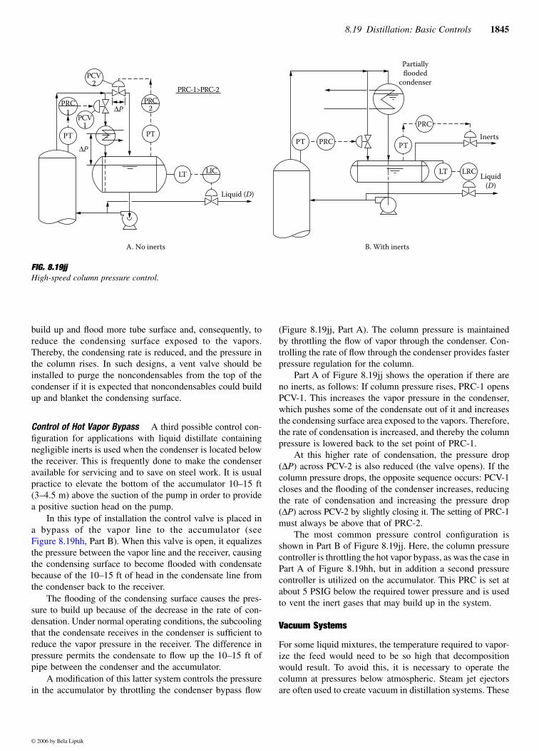
8.19 Distillation: Basic Controls 1845
build up and flood more tube surface and, consequently, toreduce the condensing surface exposed to the vapors.Thereby, the condensing rate is reduced, and the pressure inthe column rises. In such designs, a vent valve should beinstalled to purge the noncondensables from the top of thecondenser if it is expected that noncondensables could buildup and blanket the condensing surface.
Control of Hot Vapor Bypass A third possible control con-figuration for applications with liquid distillate containingnegligible inerts is used when the condenser is located belowthe receiver. This is frequently done to make the condenseravailable for servicing and to save on steel work. It is usualpractice to elevate the bottom of the accumulator 10–15 ft(3–4.5 m) above the suction of the pump in order to providea positive suction head on the pump.
In this type of installation the control valve is placed ina bypass of the vapor line to the accumulator (seeFigure 8.19hh, Part B). When this valve is open, it equalizesthe pressure between the vapor line and the receiver, causingthe condensing surface to become flooded with condensatebecause of the 10–15 ft of head in the condensate line fromthe condenser back to the receiver.
The flooding of the condensing surface causes the pres-sure to build up because of the decrease in the rate of con-densation. Under normal operating conditions, the subcoolingthat the condensate receives in the condenser is sufficient toreduce the vapor pressure in the receiver. The difference inpressure permits the condensate to flow up the 10–15 ft ofpipe between the condenser and the accumulator.
A modification of this latter system controls the pressurein the accumulator by throttling the condenser bypass flow
(Figure 8.19jj, Part A). The column pressure is maintainedby throttling the flow of vapor through the condenser. Con-trolling the rate of flow through the condenser provides fasterpressure regulation for the column.
Part A of Figure 8.19jj shows the operation if there areno inerts, as follows: If column pressure rises, PRC-1 opensPCV-1. This increases the vapor pressure in the condenser,which pushes some of the condensate out of it and increasesthe condensing surface area exposed to the vapors. Therefore,the rate of condensation is increased, and thereby the columnpressure is lowered back to the set point of PRC-1.
At this higher rate of condensation, the pressure drop(∆P) across PCV-2 is also reduced (the valve opens). If thecolumn pressure drops, the opposite sequence occurs: PCV-1closes and the flooding of the condenser increases, reducingthe rate of condensation and increasing the pressure drop(∆P) across PCV-2 by slightly closing it. The setting of PRC-1must always be above that of PRC-2.
The most common pressure control configuration isshown in Part B of Figure 8.19jj. Here, the column pressurecontroller is throttling the hot vapor bypass, as was the case inPart A of Figure 8.19hh, but in addition a second pressurecontroller is utilized on the accumulator. This PRC is set atabout 5 PSIG below the required tower pressure and is usedto vent the inert gases that may build up in the system.
Vacuum Systems
For some liquid mixtures, the temperature required to vapor-ize the feed would need to be so high that decompositionwould result. To avoid this, it is necessary to operate thecolumn at pressures below atmospheric. Steam jet ejectorsare often used to create vacuum in distillation systems. These
FIG. 8.19jjHigh-speed column pressure control.
PRC
1
PT
PCV1
PCV2
∆P
∆P
PRC2
PT
LT LIC
Liquid (D)
PRC-1>PRC-2
A. No inerts B. With inerts
PT PRC
LT LRC
PT
PRC
Partially
flooded
condenser
Inerts
Liquid
(D)
© 2006 by Béla Lipták
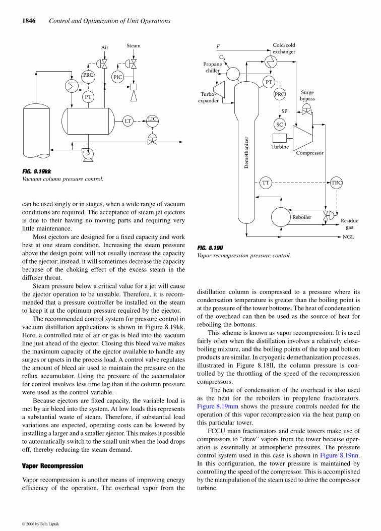
1846 Control and Optimization of Unit Operations
can be used singly or in stages, when a wide range of vacuumconditions are required. The acceptance of steam jet ejectorsis due to their having no moving parts and requiring verylittle maintenance.
Most ejectors are designed for a fixed capacity and workbest at one steam condition. Increasing the steam pressureabove the design point will not usually increase the capacityof the ejector; instead, it will sometimes decrease the capacitybecause of the choking effect of the excess steam in thediffuser throat.
Steam pressure below a critical value for a jet will causethe ejector operation to be unstable. Therefore, it is recom-mended that a pressure controller be installed on the steamto keep it at the optimum pressure required by the ejector.
The recommended control system for pressure control invacuum distillation applications is shown in Figure 8.19kk.Here, a controlled rate of air or gas is bled into the vacuumline just ahead of the ejector. Closing this bleed valve makesthe maximum capacity of the ejector available to handle anysurges or upsets in the process load. A control valve regulatesthe amount of bleed air used to maintain the pressure on thereflux accumulator. Using the pressure of the accumulatorfor control involves less time lag than if the column pressurewere used as the control variable.
Because ejectors are fixed capacity, the variable load ismet by air bleed into the system. At low loads this representsa substantial waste of steam. Therefore, if substantial loadvariations are expected, operating costs can be lowered byinstalling a larger and a smaller ejector. This makes it possibleto automatically switch to the small unit when the load dropsoff, thereby reducing the steam demand.
Vapor Recompression
Vapor recompression is another means of improving energyefficiency of the operation. The overhead vapor from the
distillation column is compressed to a pressure where itscondensation temperature is greater than the boiling point isat the pressure of the tower bottoms. The heat of condensationof the overhead can then be used as the source of heat forreboiling the bottoms.
This scheme is known as vapor recompression. It is usedfairly often when the distillation involves a relatively close-boiling mixture, and the boiling points of the top and bottomproducts are similar. In cryogenic demethanization processes,illustrated in Figure 8.18ll, the column pressure is con-trolled by the throttling of the speed of the recompressioncompressors.
The heat of condensation of the overhead is also usedas the heat for the reboilers in propylene fractionators.Figure 8.19mm shows the pressure controls needed for theoperation of this vapor recompression via the heat pump onthis particular tower.
FCCU main fractionators and crude towers make use ofcompressors to “draw” vapors from the tower because oper-ation is essentially at atmospheric pressures. The pressurecontrol system used in this case is shown in Figure 8.19nn.In this configuration, the tower pressure is maintained bycontrolling the speed of the compressor. This is accomplishedby the manipulation of the steam used to drive the compressorturbine.
FIG. 8.19kkVacuum column pressure control.
PRC
LIC
PT
PIC
LT
Air Steam
FIG. 8.19llVapor recompression pressure control.
PT
Turbo-
expander
Propane
chiller
C3
F Cold/cold
exchanger
PRC
SC
SP
TurbineCompressor
Surge
bypass
Dem
eth
aniz
er
TT TRC
NGL
Residue
gas
Reboiler
© 2006 by Béla Lipták
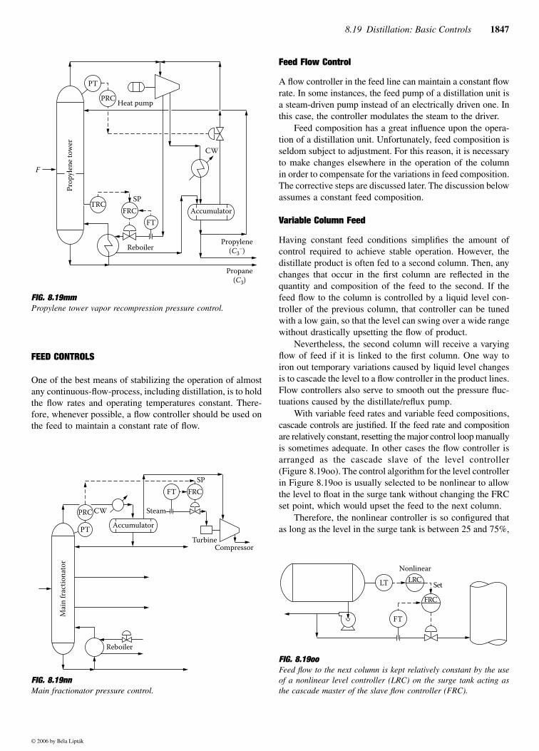
8.19 Distillation: Basic Controls 1847
FEED CONTROLS
One of the best means of stabilizing the operation of almostany continuous-flow-process, including distillation, is to holdthe flow rates and operating temperatures constant. There-fore, whenever possible, a flow controller should be used onthe feed to maintain a constant rate of flow.
Feed Flow Control
A flow controller in the feed line can maintain a constant flowrate. In some instances, the feed pump of a distillation unit isa steam-driven pump instead of an electrically driven one. Inthis case, the controller modulates the steam to the driver.
Feed composition has a great influence upon the opera-tion of a distillation unit. Unfortunately, feed composition isseldom subject to adjustment. For this reason, it is necessaryto make changes elsewhere in the operation of the columnin order to compensate for the variations in feed composition.The corrective steps are discussed later. The discussion belowassumes a constant feed composition.
Variable Column Feed
Having constant feed conditions simplifies the amount ofcontrol required to achieve stable operation. However, thedistillate product is often fed to a second column. Then, anychanges that occur in the first column are reflected in thequantity and composition of the feed to the second. If thefeed flow to the column is controlled by a liquid level con-troller of the previous column, that controller can be tunedwith a low gain, so that the level can swing over a wide rangewithout drastically upsetting the flow of product.
Nevertheless, the second column will receive a varyingflow of feed if it is linked to the first column. One way toiron out temporary variations caused by liquid level changesis to cascade the level to a flow controller in the product lines.Flow controllers also serve to smooth out the pressure fluc-tuations caused by the distillate/reflux pump.
With variable feed rates and variable feed compositions,cascade controls are justified. If the feed rate and compositionare relatively constant, resetting the major control loop manuallyis sometimes adequate. In other cases the flow controller isarranged as the cascade slave of the level controller(Figure 8.19oo). The control algorithm for the level controllerin Figure 8.19oo is usually selected to be nonlinear to allowthe level to float in the surge tank without changing the FRCset point, which would upset the feed to the next column.
Therefore, the nonlinear controller is so configured thatas long as the level in the surge tank is between 25 and 75%,
FIG. 8.19mmPropylene tower vapor recompression pressure control.
FIG. 8.19nnMain fractionator pressure control.
Pro
pyl
ene
tow
er
F
FT
TRCFRC
CW
Accumulator
PT
PRCHeat pump
Propane
(C3)
Propylene
(C3−)
SP
Reboiler
PRC
PT
CW
Accumulator
Steam
FRC
SP
TurbineCompressor
Mai
n f
ract
ion
ato
r
Reboiler
FT
FIG. 8.19ooFeed flow to the next column is kept relatively constant by the useof a nonlinear level controller (LRC) on the surge tank acting asthe cascade master of the slave flow controller (FRC).
LT
FT
LRC
FRC
Nonlinear
Set
© 2006 by Béla Lipták
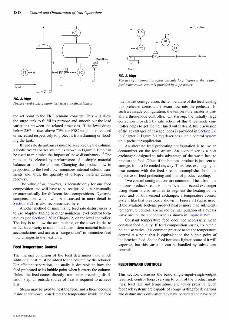
1848 Control and Optimization of Unit Operations
the set point to the FRC remains constant. This will allowthe surge tank to fulfill its purpose and smooth out the loadvariations between the related processes. If the level dropsbelow 25% or rises above 75%, the FRC set point is reducedor increased respectively to protect it from draining or flood-ing the tank.
If feed rate disturbances must be accepted by the column,a feedforward control system as shown in Figure 8.19pp canbe used to minimize the impact of these disturbances.10 Theratio, m, is selected by performance of a simple materialbalance around the column. Changing the product flow inproportion to the feed flow minimizes internal column tran-sients and, thus, the quantity of off-spec material duringrecovery.
The value of m, however, is accurate only for one feedcomposition and will have to be readjusted either manuallyor automatically for different feed compositions. Dynamiccompensation, which will be discussed in more detail inSection 8.21, is also recommended here.
Another method of minimizing feed rate disturbances isto use adaptive tuning or other nonlinear level control tech-niques (see Section 2.36 in Chapter 2) on the level controller.The key is to allow the accumulator, or the tower kettle, toutilize its capacity to accommodate transient material balanceaccumulations and act as a “surge drum” to minimize feedflow changes to the next unit.
Feed Temperature Control
The thermal condition of the feed determines how muchadditional heat must be added to the column by the reboiler.For efficient separation, it usually is desirable to have thefeed preheated to its bubble point when it enters the column.Unless the feed comes directly from some preceding distil-lation step, an outside source of heat is required to achievethat.
Steam may be used to heat the feed, and a thermocoupleinside a thermowell can detect the temperature inside the feed
line. In this configuration, the temperature of the feed leavingthis preheater controls the steam flow into the preheater. Insuch a cascade configuration, the temperature master is usu-ally a three-mode controller. On start-up, the initially largecorrection provided by rate action of this three-mode con-troller helps to get the unit lined out faster. A full discussionof the advantages of cascade loops is provided in Section 2.6in Chapter 2. Figure 8.19qq describes such a control systemon a preheater application.
An alternate feed preheating configuration is to use aneconomizer on the feed stream. An economizer is a heatexchanger designed to take advantage of the waste heat topreheat the feed. Often, if the bottoms product is just sent tostorage, it must be cooled anyway. Therefore, exchanging itsheat content with the feed stream accomplishes both theobjective of feed preheating and that of product cooling.
Two control configurations are common. If heat from thebottoms product stream is not sufficient, a second exchangerusing steam is also installed to augment the heating of thefeed, and on this second exchanger, a temperature controlsystem like that previously shown in Figure 8.19qq is used.If the available bottoms product heat is more than sufficient,temperature control is achieved by manipulation of a bypassvalve around the economizer, as shown in Figure 8.19rr.
Constant temperature feed does not necessarily meanconstant feed quality. If feed composition varies, its bubblepoint also varies. It is common practice to set the temperaturecontrol at a point that is equivalent to the bubble point ofthe heaviest feed. As the feed becomes lighter, some of it willvaporize, but this variation can be handled by subsequentcontrols.
FEEDFORWARD CONTROLS
This section discusses the basic single-input–single-outputfeedback control loops, serving to control the product qual-ities, feed rate and temperature, and tower pressure. Suchfeedback systems are capable of compensating for deviationsand disturbances only after they have occurred and have been
FIG. 8.19ppFeedforward control minimizes feed rate disturbances.
FT FYX
FC
Feedm
Distillate
FIG. 8.19qqThe use of a temperature-flow cascade loop improves the columnfeed temperature controls provided by a preheater.
TRC
TT
FRC
FT
Set
Feed
Steam
To column
© 2006 by Béla Lipták
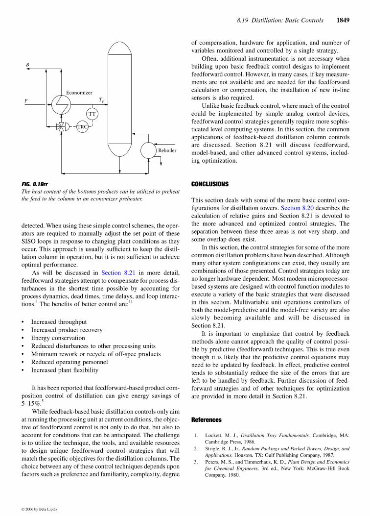
8.19 Distillation: Basic Controls 1849
detected. When using these simple control schemes, the oper-ators are required to manually adjust the set point of theseSISO loops in response to changing plant conditions as theyoccur. This approach is usually sufficient to keep the distil-lation column in operation, but it is not sufficient to achieveoptimal performance.
feedforward strategies attempt to compensate for process dis-turbances in the shortest time possible by accounting forprocess dynamics, dead times, time delays, and loop interac-tions.1 The benefits of better control are:11
• Increased throughput• Increased product recovery• Energy conservation• Reduced disturbances to other processing units• Minimum rework or recycle of off-spec products• Reduced operating personnel• Increased plant flexibility
It has been reported that feedforward-based product com-position control of distillation can give energy savings of5–15%.5
While feedback-based basic distillation controls only aimat running the processing unit at current conditions, the objec-tive of feedforward control is not only to do that, but also toaccount for conditions that can be anticipated. The challengeis to utilize the technique, the tools, and available resourcesto design unique feedforward control strategies that willmatch the specific objectives for the distillation columns. Thechoice between any of these control techniques depends uponfactors such as preference and familiarity, complexity, degree
of compensation, hardware for application, and number ofvariables monitored and controlled by a single strategy.
Often, additional instrumentation is not necessary whenbuilding upon basic feedback control designs to implementfeedforward control. However, in many cases, if key measure-ments are not available and are needed for the feedforwardcalculation or compensation, the installation of new in-linesensors is also required.
Unlike basic feedback control, where much of the controlcould be implemented by simple analog control devices,feedforward control strategies generally require more sophis-ticated level computing systems. In this section, the commonapplications of feedback-based distillation column controlsare discussed. Section 8.21 will discuss feedforward,model-based, and other advanced control systems, includ-ing optimization.
CONCLUSIONS
This section deals with some of the more basic control con-figurations for distillation towers. Section 8.20 describes thecalculation of relative gains and Section 8.21 is devoted tothe more advanced and optimized control strategies. Theseparation between these three areas is not very sharp, andsome overlap does exist.
In this section, the control strategies for some of the morecommon distillation problems have been described. Althoughmany other system configurations can exist, they usually arecombinations of those presented. Control strategies today areno longer hardware dependent. Most modern microprocessor-based systems are designed with control function modules toexecute a variety of the basic strategies that were discussedin this section. Multivariable unit operations controllers ofboth the model-predictive and the model-free variety are alsoslowly becoming available and will be discussed inSection 8.21.
It is important to emphasize that control by feedbackmethods alone cannot approach the quality of control possi-ble by predictive (feedforward) techniques. This is true eventhough it is likely that the predictive control equations mayneed to be updated by feedback. In effect, predictive controltends to substantially reduce the size of the errors that areleft to be handled by feedback. Further discussion of feed-forward strategies and of other techniques for optimizationare provided in more detail in Section 8.21.
References
1. Lockett, M. J., Distillation Tray Fundamentals, Cambridge, MA:Cambridge Press, 1986.
2. Strigle, R. J., Jr., Random Packings and Packed Towers, Design, andApplications, Houston, TX: Gulf Publishing Company, 1987.
3. Peters, M. S., and Timmerhaus, K. D., Plant Design and Economicsfor Chemical Engineers, 3rd ed., New York: McGraw-Hill BookCompany, 1980.
FIG. 8.19rrThe heat content of the bottoms products can be utilized to preheatthe feed to the column in an economizer preheater.
F
TRC
TT
B
Economizer
TF
Reboiler
© 2006 by Béla Lipták
As will be discussed in Section 8.21 in more detail,
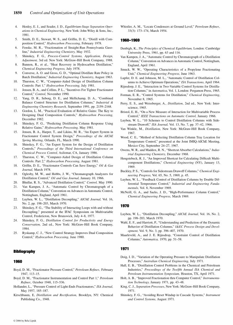
1850 Control and Optimization of Unit Operations
4. Henley, E. J., and Seader, J. D., Equilibrium-Stage Separation Oper-ations in Chemical Engineering, New York: John Wiley & Sons, Inc.,1981.
5. Smith, D. E., Stewart, W. S., and Griffin, D. E., “Distill with Com-position Control,” Hydrocarbon Processing, February 1978.
6. Fenske, M. R., “Fractionation of Straight-Run Pennsylvania Gaso-line,” Industrial Engineering Chemistry, May 1932.
7. Shinskey, F. G., Process-Control Systems, Application, Design,Adjustment, 3rd ed. New York: McGraw-Hill Book Company, 1988.
8. Bannon, R., et al., “Heat Recovery in Hydrocarbon Distillation,”Chemical Engineering Progress, July 1978.
9. Converse, A. O. and Gross, G. D., “Optimal Distillate Rate Policy inBatch Distillation,” Industrial Engineering Chemistry, August 1963.
10. Thurston, C. W., “Computer-Aided Design of Distillation ColumnControls: Part 1,” Hydrocarbon Processing, July 1981.
11. Jensen, B. A., and Collins, P. L., “Incentives For Tighter FractionatorControl,” Control, November 1990.
12. Yang, D. R., Seborg, D. E., and Mellichamp, D. A., “CombinedBalance Control Structure for Distillation Columns,” Industrial &Engineering Chemistry Research, September 1991, pp. 2159–2168.
13. Gordon, L. M., “Practical Evaluation of Relative Gains: The Key toDesigning Dual Composition Controls,” Hydrocarbon Processing,December 1982.
14. Shinskey, F. G., “Predicting Distillation Column Response UsingRelative Gains,” Hydrocarbon Processing, May 1981.
15. Jensen, B. A., Harper, T., and Likins, M. R., “An Expert System inFractionator Control System Design,” Proceedings of the AIChESpring Meeting, Orlando, FL, March 1990.
16. Shinskey, F. G., “An Expert System for the Design of DistillationControls,” Proceedings of the Third International Conference onChemical Process Control, Asilomar, CA, January 1986.
17. Thurston, C. W., “Computer-Aided Design of Distillation ColumnControls: Part 2,” Hydrocarbon Processing, August 1981.
18. Griffin, D. E., “Fractionator Controls Can Save Energy,” Oil & GasJournal, March 1978.
19. Oglesby, M. W., and Hobbs, J. W., “Chromatograph Analyzers forDistillation Control,” Oil and Gas Journal, January 10, 1966.
20. Bhullar, R. S., “Advanced Distillation Control,” Control, May 1990.21. Van Kampen, J. A., “Automatic Control by Chromatograph of a
Distillation Column,” Convention on Advances in Automatic Control,Nottingham, England, April 1961.
22. Luyben, W. L., “Distillation Decoupling,” AIChE Journal, Vol. 16,No. 2, pp. 198–203, March 1970.
23. Shinskey, F. G., “The Stability of Interacting Loops with and withoutDecoupling,” presented at the IFAC Symposium on MultivariableControl, Fredericton, New Brunswick, July 4–8, 1977.
24. Shinskey, F. G., Distillation Control for Productivity and EnergyConservation, 2nd ed., New York: McGraw-Hill Book Company,1984.
25. Ryskamp, C. J., “New Control Strategy Improves Dual CompositionControl,” Hydrocarbon Processing, June 1980.
Bibliography
1960
Boyd, D. M., “Fractionator Pressure Control,” Petroleum Refiner., February1947, 113–15.
Boyd, D. M., “Fractionator Instrumentation and Control Part 1,” PetroleumRefiner., October 1948, 115–536.
Hollander, L., “Pressure Control of Light-Ends Fractionators,” ISA Journal,May 1957, 185–187.
Kirschbaum, E, Distillation and Rectification, Brooklyn, NY: ChemicalPublishing Co., 1948.
Whistler, A. M., “Locate Condensers at Ground Level,” Petroleum Refiner.,33(3): 173–174, March 1954.
1960–1969
Denbigh, K., The Principles of Chemical Equilibrium, London: CambridgeUniversity Press, 1961, pp. 63 and 116.
Van Kampen, J. A., “Automatic Control by Chromatograph of a DistillationColumn,” Convention on Advances in Automatic Control, Nottingham,England, April 1961.
Smuck, W. W., “Operating Characteristics of a Propylene FractionatingUnit,” Chemical Engineering Progress, June 1963.
Lupfer, D. E. and Johnson, M. L., “Automatic Control of Distillation Col-umns to Achieve Optimum Operations,” ISA Transactions, April 1964.
Rijnsdorp, J. E., “Interaction in Two-Variable Control Systems for Distilla-tion Columns,” in Automatica, Vol. 1, London: Pergamon Press, 1965.
Forman, E. R., “Control Systems for Distillation,” Chemical Engineering,November 8, 1965.
Perry, E. S., and Weissberger, A., Distillation, 2nd ed., New York: Inter-science, 1965.
Bristol, E. H., “On a New Measure of Interaction for Multivariable ProcessControl,” IEEE Transactions on Automatic Control, January 1966.
Luyben, W. L., “10 Schemes to Control Distillation Columns with Side-stream Drawoff,” ISA Journal, Vol. 13, No. 7, pp. 37–42, 1966.
Van Winkle, M., Distillation, New York: McGraw-Hill Book Company,1967.
Wood, C. E., “Method of Selecting Distillation Column Tray Location forTemperature Control,” presented at the Joint IMIQ-AIChE Meeting,Mexico City, September 24–27, 1967.
Owens, W. R., and Maddox, R. N., “Shortcut Absorber Calculations,” Indus-trial Engineering Chemistry, December 1968.
Hengstebeck, R. J., “An Improved Shortcut for Calculating Difficult Multi-component Distillations,” Chemical Engineering (NY), January 13,1969.
Buckley, P. S., “Controls for Sidestream Drawoff Columns,” Chemical Engi-neering Progress, Vol. 65, No. 5, 1969, p. 45.
Luyben, W. L., “Feedback Control of Distillation Columns by Double Dif-ferential Temperature Control,” Industrial and Engineering Funda-mentals, Vol. 8, November 1969.
McNeill, G. A., and Sacks, J. D., “High-Performance Column Control,”Chemical Engineering Progress, March 1969.
1970
Luyben, W. L., “Distillation Decoupling,” AIChE Journal, Vol. 16, No. 2,pp. 198–203, March 1970.
Wahl, E. F., and Harriott, P., “Understanding and Prediction of the DynamicBehavior of Distillation Columns,” I&EC Process Design and Devel-opment, Vol. 9, No. 3, pp. 396–407, 1970.
Maarleveld, A., and J. E. Rijnsdrop, “Constraint Control of DistillationColumns,” Automatica, 1970, pp. 51–58.
1971
Doig, I. D., “Variation of the Operating Pressure to Manipulate DistillationProcesses,” Australian Chemical Engineering, July 1971.
Hall, E. B., “Distillation Control Problems in the Chemical and PetroleumIndustries,” Proceedings of the Twelfth Annual ISA Chemical andPetroleum Instrumentation Symposium, Houston, TX, April 1971.
Holt, A. B., “Improved Fractionation thru Computer Control,” Instrumenta-tion Technology, January 1971, pp. 43–48.
King, C. J., Separation Processes, New York: McGraw-Hill Book Company,1971.
Shinskey, F. G., “Avoiding Reset Windup in Cascade Systems,” Instrumentand Control Systems, August 1971.
© 2006 by Béla Lipták
8.19 Distillation: Basic Controls 1851
Shinskey, F. G., “When to Use Valve Positioners,” Instrument and ControlSystems, September 1971.
Shinskey, F. G., “When You Have the Wrong Valve Characteristic,” Instru-ment and Control Systems, October 1971.
Shunta, J. P., and Luyben, W. L., “Dynamic Effects of Temperature ControlTray Location in Distillation Columns,” AIChE Journal, Vol. 17, No. 1,pp. 92–96, January 1971.
1972
Toijala, K., and Fagervik, K., “A Digital Simulation Study of Two-PointFeedback Control of Distillation Columns,” Kem. Teollisuus, January1972.
Shinskey, F. G., “What to Know about Interaction between Control Loops,”Canadian Controls Instrumentation, March 1972.
McFarlane, A. G. J., “A Survey of Some Recent Results in Linear Multi-variable Feedback Theory,” Automatica, Vol. 8, No. 4, pp. 455–492,1972.
Shinskey, F. G., “Effective Control for Automatic Start-up and Plant Pro-tection,” Canadian Controls Instrumentation, April 1972.
Shinskey, F. G., “Controlling Surge-Tank Level,” Instrument and ControlSystems, September 1972.
Shinskey, F. G., “Controlling Variable Period Once-Through Processes,”Instrument and Control Systems, November 1972.
White, M. H., “Surge Control for Centrifugal Compressors,” Chemical Engi-neering (NY), December 25, 1972.
1973
Evans, F. L., Equipment Design Handbook for Refineries and ChemicalPlants, Vol. I, Houston, TX: Gulf Publishing Co., 1973, p. 89.
Perry, J. H., Chemical Engineers’ Handbook, 5th ed., New York: McGraw-Hill Book Company, 1973.
Houghton, J., and McLay, J. D., “Turboexpanders Aid Condensate Recov-ery,” Oil and Gas Journal, March 5, 1973.
Sayles, J. H., “Computer Control Maximizes Hydrocracker Throughput,”Instrumentation Technology, May 1973.
Frank, O., and Prickett, R. D., “Designing Vertical Thermosyphon Reboil-ers,” Chemical Engineering (NY), September 3, 1973.
Sisson, B., “How to Determine MEA Circulation Rates,” Chemical Engi-neering (NY), November 26, 1973.
O’Conner, J., and Illing, H., “The Turbine Control Valve. A New Approachto High-Loss Applications,” Instrumentation Technology, December1973.
1974
Ackley, W. R., “Feedforward Control Strategy for Distillation Towers,”Instrumentation Technology, February 1974.
Adiutori, E. F., The New Heat Transfer, Cincinnati, OH: Ventuno Press, 1974,Chapter 7.
Kline, P. E., “Technical Task Force Approach to Energy Conservation,”Chemical Engineering Progress, February 1974.
Shinskey, F. G., “Values of Process Control,” Oil and Gas Journal, February18, 1974.
Ellerbe, R. W., “Steam Distillation Basics,” Chemical Engineering (NY),March 4, 1974.
Lupter, D. E., “Distillation Column Control for Utility Economy,” presentedat 53rd Annual GPA Convention, Denver, March 25–27, 1974.
Waller, K. V. T., “Decoupling in Distillation,” AIChE Journal, May 1974.Farwell, W., “More Cooling at Less Cost,” Plant Engineering, August 1974.Gallier, P. W., and McCune, L. C., “Simple Internal Reflux Control,” Chem-
ical Engineering Progress, September 1974.Rathore, R. N. S., VanWorme, K. A., and Powers, G. J., “Synthesis of
Distillation Systems with Energy Integration,” AIChE Journal,September 1974.
Buckley, P. S., “Material Balance Control in Distillation Columns,” pre-sented at AIChE Workshop on Industrial Process Control, Tampa, FL,November 11–13, 1974.
1975
Bojnowski, J. H., Crandall, J. W., and Hoffman, R. M., “Modernized Sep-aration Systems Saves More than Energy,” Chemical EngineeringProgress, October 1975.
Boyd, D. M., “Fractionation Column Control,” Chemical Engineering, June1975.
Buckley, P. S., Cox, R. K., and Rollins, D. L., “Inverse Response in aDistillation Column,” Chemical Engineering Progress, June 1975.
Franzke, A., “Save Energy with Hydraulic Power Recovery Turbines,”Hydrocarbon Process, March 1975.
Luyben, W. L., “Steady-State Energy Conservation Aspects of DistillationColumn Control Design,” I&EC Fundam., Vol. 14, No. 4, pp. 321–325,1975.
Monroe, E. S., “Vacuum Pumps Can Conserve Energy,” Oil and Gas Jour-nal, February 3, 1975.
Rademaker, O., Rijnsdorp, J. E., and Maarleveld, A., Dynamics and Controlsof Continuous Distillation Units, Amsterdam: Elsevier, 1975.
Shinskey, F. G., “Controlling Unstable Processes, Part II: A Heat Exchange,”Instrument and Control Systems, January 1975.
Sternlicht, B., “Low-Level Heat Recovery Takes on Added Meaning as FuelCosts Justify Investment,” Power, April 1975.
Tyreus, B., and Luyben, W. L., “Control of a Binary Distillation Columnwith Sidestream Drawoff,” I&EC Process Design and Development,Vol. 14, No. 4, p. 391, 1975.
Tyreus, B., and Luyben, W. L., “Two Towers Cheaper than One?” Hydro-carbon Processing, Jun., 1975.
Wolf, C. W., Weiler, D. W., and Ragi, E. G., “Energy Costs Prompt ImprovedDistillation,” Oil and Gas Journal, September 1, 1975.
1976
ISA Standard S51.1, “Process Instrumentation Terminology,” Research Tri-angle Park, NC: Instrument Society of America, 1993.
Shinskey, F. G., “Energy-Conserving Control for Distillation Units,” Chem-ical Engineering Progress, May 1976.
Wright, R. M., “A Better Approach to Distillation Control,” Instruments andControl Systems, June 1976.
Van Horn, L. D., and Latour, P. R., “Computer Control of a Crude Still,”Instrumentation Technology, November 1976, pp. 33–39.
VanWinkle, M., Distillation, New York: McGraw-Hill, 1976.
1977
Hadley, K., “Control Objectives Analysis,” National Petroleum RefinersAssociation Computer Conference, New Orleans, 1977.
Hobbs, J. W., “Unifying Concepts for Fractionator Product CompositionControl,” Proceedings of the Automatic Control Conference, SanFrancisco, 1977.
Evans, L. B., “Impact of the Electronics Revolution on Industrial ProcessControl,” Science, Vol. 195, No. 4283, March 18, 1977.
Hughart, C. L., “Designing Distillation Units for Controllability,” Instru-mentation Technology, May 1977.
Lieberman, N., “Instrumenting a Plant to Run Smoothly,” Chemical Engi-neering, September 12, 1977, pp. 140–154.
Shinskey, F. G., “The Stability of Interacting Loops with and without Decou-pling,” presented at the IFAC Symposium on Multivariable Control,Fredericton, New Brunswick, July 4–8, 1977.
© 2006 by Béla Lipták
1852 Control and Optimization of Unit Operations
1978
Buckley, P. S., Cox, R. K., and Luyben, W. L., “How to Use a SmallCalculator in Distillation Column Design,” Chemical EngineeringProgress, June 1978, pp. 49–55.
Buckley, P. S., “Distillation Column Design Using Multivariable Control,”Instrumentation Technology, September/October 1978.
Buford, B. N., Bush, B. A., and Staten, H. W., “Computers Conserve Energyin NGL Fractionators,” Oil & Gas Journal, December 1978.
Doukas, N., “Control of Sidestream Columns Separating Ternary Mixtures,”Instrumentation Technology, June 1978.
Doukas, N. and Luyben, W. L., “Economics of Alternative Distillation Con-figurations for the Separation of Ternary Mixtures,” I&CE ProcessDesign and Development, Vol. 17, No. 272, 1978.
Griffin, D. E., Parsons, J. R., and Smith, D. E., “The Use of Process Ana-lyzers for Composition Control of Fractionators,” Proceedings of theISA Spring Joint Conference, Houston, TX, May 1978.
Latour, P. R., “Composition Control of Distillation Columns,” Instrumenta-tion Technology, July 1978.
Lamb, M. Y., “Computer Control of a Propylene Upgrading Unit,” 85thNational AIChE Meeting, Philadelphia, PA, 1978.
McCoy, R. D., “Adding Capabilities to Process Chromatography withMicroprocessor-Based Programmers,” Proceedings of the ISA JointSpring Conference, Houston, TX, May 1978.
Mix, T. J., Dweck, J. S., Weinberg, M., and Armstrong, R. C., “EnergyConservation in Distillation,” Chemical Engineering Progress, April1978.
Painter, J. W., and Gonnella, J. L., “Improved Control of a DistillationColumn Using a Minicomputer and an On-Line Gas Chromatograph,”Texas A&M Instrumentation Symposium, January 1978.
Tolliver, T. L., and McCune, L. C., “Distillation Column Control DesignBased on Steady State Simulation,” ISA Transactions, Vol. 17, No. 3,pp. 3–10, 1978.
1979
Watkins, R. N., Petroleum Refinery Distillation, 2nd ed., Houston, TX: GulfPublishing Company, 1979.
Douglas, J. M., Jafarey, A., and McAvoy, T. J., “Shortcut Techniques forDistillation Column Design and Control, Part 1: Column Design,” I&ECProcess Design and Development, Vol. 18, pp. 197–202, April 1979.
Van Horn, L. D., “Computer Control. How to Get Started,” HydrocarbonProcessing, September 1979.
Chin, T. G., “Guide to Distillation Pressure Control Methods,” HydrocarbonProcessing, October 1979, 145–153.
1980
Treybal, R. E., Mass-Transfer Operations, 3rd ed., New York: McGraw-HillBook Company, 1980.
Van Horn, L. D., “Crude Unit Computer Control. How Good Is It?” Hydro-carbon Processing, April 1980.
Ryskamp, C. J., “New Control Strategy Improves Dual Composition Con-trol,” Hydrocarbon Processing, June 1980.
Soderstrom, E. D., ‘‘Computer Control for Energy Savings,” Chemical Engi-neering Progress, August 1980, pp. 60–62.
Black, C., “Distillation Modeling of Ethanol Recovery and DehydrationProcess for Ethanol and Gasohol,” Chemical Engineering Progress,September 1980.
Andrews, A. J., and Griffin, D. E., “Performance Audits Evaluate TwoDistillation Control Projects,” Oil & Gas Journal, December 8, 1980.
1981
Griffin, D. E., “Tighten Distillation Column Control and Save Energy,”Instruments and Control Systems, March 1981.
Black, J. W., “Model Estimates Analyzer Payouts,” Hydrocarbon Process-ing, September 1981.
Shinskey, F. G., “Controlling Distillation Processes for Fuel-Grade Alcohol,”Instruments and Control Systems, December 1981.
Thurston, C. W., “Computer-Aided Design of Distillation Column Controls,”Hydrocarbon Processing, Part 2, August 1981, p. 5.
1982
Rinne, R., Sunnel, H., Latour, P. R., and Payntex, K. K., “Experience withDistillation Unit Computer Control,” Hydrocarbon Processing, March1982.
Roffel, B., and Rijnsdorp, J. E., Process Dynamics, Control, and Protection,Ann Arbor, MI: Ann Arbor Science, 1982.
DiBano, R. J., “Advanced Control: General Purpose Design vs. Working ItOut in the Field,” Hydrocarbon Processing, August 1982.
Dweck, J. S. and Mix, T. W., Conserving Energy in Distillation, MIT Press,1982.
1984
Mix, P. E., The Design and Application of Process Analyzer Systems, NewYork: John Wiley & Sons, Inc., 1984.
Stephanopoulos, G., Chemical Process Control, An Introduction to Theoryand Practice, Englewood Cliffs, NJ: Prentice Hall, 1984.
Barduhn, A. J., “Setting the Pressure at which to Conduct a Distillation,”Chemical Engineering Education, Vol. 18, No. 1, pp. 38–40, 1984.
1985
Deshpande, P. B., Distillation Dynamics and Control, Research TrianglePark, NC: Instrument Society of America, 1985.
Buckley, P. S., Luyben, W. L., and Shunta, J. P., Design of DistillationColumn Control System, Research Triangle Park, NC: Instrument Soci-ety of America, 1985.
Gani, R., Romagnoli, J. A., and Stephanopoulos, G., “Control Studies in anExtractive Distillation Process: Simulation and Measurement Struc-ture,” Chem. Engng. Commun., 40, pp. 281–302, 1985.
1986
Tsai, T. H., Lane, J. W., and Lin, C. S., Modern Control Techniques for theProcess Industries, Vol. 23, Marcel Dekker, 1986.
Hansen, T. T., and Jørgensen, S. B., “Optimal Open Loop Control of BinaryBatch Distillation,” Chem. Eng. J., 33 , pp. 151–155, 1986.
1987
Christensen, F. M., and Jørgensen, S.B., “Optimal Open Loop Control ofBinary Batch Distillation with Recycled Waste Cut,” Chem. Eng. J., 34,pp. 57–64, 1987.
1988
Balchen, J. G., Process Control, Structures, and Applications, New York:Van Nostrand Reinhold, 1988.
Birky, G. J., McAvoy, T. J., and Tyreus, B. D., “Expert System for Designof Distillation Controls,” Proceedings of the ISA/88 International Con-ference and Exhibit, Houston, TX, October 1988.
Murrill, P. W., Application Concepts of Process Control Theory, ResearchTriangle Park, NC: Instrument Society of America, 1988.
Nichols, G. D., On-Line Process Analyzers, New York: John Wiley & Sons,Inc., 1988.
Roat, S. D., Moore, C. F., and Downs, J. J., “A Steady-State DistillationColumn Control System Sensitivity Analysis Technique,” ProceedingsIEEE Southeast Con., 1988, pp. 296–300.
© 2006 by Béla Lipták

8.19 Distillation: Basic Controls 1853
1989
Finco, M. V., Luyben, W. L., and Polleck, R. G., ‘‘Control of DistillationColumns with Low Relative Volatilities,” Ind. Eng. Chem. Res., Vol. 28,January 1989, pp. 75–83.
Wassick, J. M. and Tummala, R. L., “Multivariable Internal Model Controlfor a Full-Scale Industrial Distillation Column,” Control Systems Mag-azine, January 1989, pp. 91–96.
Seborg, D. E., Edgar, T. F., and Mellichamp, D. A., Process Dynamics andControl, New York: John Wiley & Sons, Inc., 1989.
Hall, G. F., “Improve Process Performance by Using Chromatograph-Directed Control,” Proceedings of the ISA/89 International Conferenceand Exhibit, Part 1, Philadelphia, PA, October 1989.
Christie, D. A., “The Top-Down Approach to Successful Process ControlProjects,” Control, October 1989.
Luyben, W. L., Process Modeling, Simulation, and Control for ChemicalEngineers, 2nd ed., New York: McGraw-Hill Book Company, 1989.
Kister, H. Z., Distillation Operation, New York: McGraw-Hill PublishingCompany, 1989.
Riggs, J. B., Sinha, R., “High Purity Distillation Control Using NonlinearProcess Model-Based Control,” ISA89, Philadelphia, PA, October 1989.
Riggs, J. B., “Nonlinear Process Model-Based Control of a DistillationColumn with a Sidestream Draw-Off,” presented at the annual AIChEmeeting, San Francisco, CA, November 1989.
Riggs, J. B., Sinha, R., and McDaniel, R., “Comparison of Control Tech-niques for High Purity Distillation Columns,” AIChE Spring NationalMeeting, Houston, TX, April 1989.
1990
Papastathopoulou, H. S., and Luyben, W. L., “Turning Controllers on Distilla-tion Columns with the Distillated Bottoms Structure,” Industrial andEngineering Chemistry Research, Vol. 29, September 1990, pp. 1859–1868.
Chien, I.-L., and Fruehauf P. S., “Consider IMC Tuning to Improve Con-troller Performance,” Chemical Engineering Progress, Vol. 86, No. 10,pp. 33–41, October 1990.
Cingara, A., Jovanovic, M., and Mitrovic, M., “Analytical First-OrderDynamic Model of Binary Distillation Column,” Chemical Engineer-ing Science, Vol. 45, No. 12, pp. 3585–3592, 1990.
Kister, H. Z., Distillation Operation, New York: McGraw-Hill Book Com-pany, 1990.
Li, R., Olson, J. H., and Chester, D. L., “Dynamic Fault Detection andDiagnosis Using Neural Networks,” Proceedings of the Fifth IEEEInternational Symposium on Intelligent Control, Philadelphia, PA,September 1990, pp. 1169–1174.
McGreavy, C., Dynamics and Control of Chemical Reactors, DistillationColumns, and Batch Processes, Pergamon Press, 1990.
Papastathopoulou, H. S. and Luyben, W. L., “Potential Pitfalls in RatioControl Schemes,” Industrial & Engineering Chemistry Research,October 1990, pp. 2044–2053.
Pitt, M. J., Instrumentation and Automation in Process Control, New York:Horwood, 1990.
Skogestad, S., Lundstrom, P., and Jacobsen, E. W., “Selecting the BestDistillation Control Configuration,” AIChE Journal, Vol. 36,pp. 753–764, 1990.
Skogestad, S., Jacobsen, E. W., and Morari, M., “Inadequacy of Steady-State Analysis for Feedback Control. Distillate. Bottom Control ofDistillation Columns,” Industrial & Engineering Chemistry Research,December 1990, pp. 2339–2346.
Pandit, H. G., and Rhinehart, R. R., “Process Model-Based Control of aNonideal Binary Distillation Column,” Proceedings of the AnnualAIChE Meeting, Chicago, IL, November 1990.
Pedersen, N. H., and Jørgensen, S. B., “A GC Subsystem for Fast On-LineConcentration Profile Measurement for Advanced Distillation Con-trol,” Analytica Chemica Acta, 238, pp. 139–148, 1990.
Riggs, J. B., Watts, J., and Beauford, M., “Advanced Model-Based Controlfor Distillation,” National Petroleum Refinery Association Meeting,Seattle, WA, October 1990.
Riggs, J. B., Watts, J., and Beauford, M., “Industrial Experience with Apply-ing Nonlinear Process Model-Based Control to Distillation Columns,”ISA90, New Orleans, LA, October 1990.
Riggs, J. B., “Advanced Model-Based Control of a Sidestream Draw Col-umn,” at ISA 90, New Orleans, LA, October 1990.
1991
Coughanowr, D. R., Process Systems Analysis and Control, 2nd ed., NewYork: McGraw-Hill Book Company, 1991.
Jensen, B. A., “Improve Control of Cryogenic Gas Plants,” HydrocarbonProcessing, May 1991.
Papastathopoulou, H. S., and Luyben, W. L., “Control of a Binary SidestreamDistillation Column,” Industrial & Engineering Chemistry Research,April 1991, pp. 705–713.
Rijnsdorp, J. E., Integrated Process Control and Automation, Amsterdam:Elsevier, 1991.
Sandelin, P. M., Haeggblom, K. E., and Waller, K. V., “Disturbance RejectionProperties of Control Structures at One-Point Control of a Two-ProductDistillation Column,” Industrial & Engineering Chemistry Research,June 1991, pp. 1182–1186.
Sandelin, P. M., Haeggblom, K. E., and Waller, K. V., “Disturbance Sensi-tivity Parameter and its Application to Distillation Control,” Industrial& Engineering Chemistry Research, June 1991, pp. 1187–1193.
1992
Fruehauf, P. S., and Mahoney, D. P. “Distillation Column Control Designusing Steady-State Models, Usefulness and Limitations,” in Advancesin Instrumentation and Control, Vol. 47, Part 1, Research TrianglePark, NC: Instrument Society of America, 1992, pp. 92–120.
Skogestad, S., “Dynamics and Control of Distillation Columns: A CriticalSurvey,” Preprints IFAC Symposium, DYCORD +92, College Park,MD, pp. 1–25.
Luyben, W. L., Practical Distillation Control,” New York: Van NostrandReinhold, October 1992.
Koggersbøl, A., and Jørgensen, S. B., “Dynamics and Control of a Distilla-tion Column with a Sidestream,” IChemE Symposium Series, 128,pp. A429–A449, 1992.
1993
Fruehauf, P. S., and Mahoney, D. P., “Distillation Column Control DesignUsing Steady State Models: Usefulness and Limitations,” ISA Trans-actions, Research Triangle Park, NC. 1993.
Balchen, J. G., Dynamics and Control of Chemical Reactors, DistillationColumns, and Batch Processes, Pergamon Press, April 1993.
Ganguly, S., “Model Predictive Control of Distillation,” ISA/93 TechnicalConference, Chicago, IL, September 1993.
1994
Gokhale, V., Shukla, N., and Munsif, H., “Analysis of Advanced DistillationControl on a C3 Splitter and a Depropanizer,” 1994 AIChE NationalAnnual Meeting, San Francisco, CA, November 1994.
Fruehauf, P. S., and Mahoney, D. P., “Improve Distillation Column ControlDesign,” Chemical Engineering Progress, March 1994.
1995
Fleming, B., and Sloley, A. W., “Feeding and Drawing Products: The For-gotten Part of Distillation,” Proceedings of the ChemShow and Expo-sition, New York, December 1995.
© 2006 by Béla Lipták

1854 Control and Optimization of Unit Operations
Musch, H. E., and Steiner, M., “Robust PID Control for an Industrial Dis-tillation Column,” Control System Magazine, Vol. 15, No. 4, 46–55,1995.
Hurowitz, S. E., and Gokhale, V., “A Dynamic Model of a Superfraction-ator: A Test Case for Comparing Distillation Control Techniques,”DYCORD ‘95, 4th IFAC Symposium, Helsingor, Denmark, June1995.
Lundstrom, P., and Skogestad, S., “Opportunities and Difficulties with 5 × 5Distillation Control,” J. Process Control, Vol. 5, 249–261, 1995.
Rawlings, J. B., “Dynamics and Control of Chemical Reactors, DistillationColumns, and Batch Processes (Dycord+‘95),” a Postprint Volumefrom the 4th IFAC Symposium on Dynamics and Control of ChemicalReactors, Distillation Columns and Batch Processes (DYCORD ‘95),Helsingor, Denmark, June 1995.
Diwekar, U. M., “Batch Distillation: Simulation, Optimal Design, and Con-trol (Series in Chemical and Mechanical Engineering),” Taylor & Fran-cis, September 1995.
Banerjee, A., and Arkun, Y., “Control Configuration Design Applied to theTennessee Eastman Plantwide Control Problem,” Computers & Chem.Eng., 19(4), 453–480, 1995.
1996
Koggersbøl, A., Andersen, R., Nielsen, J. S., Jørgensen, S., “Control Con-figuration for Energy Integrated Distillation,” Computers & Chem.Eng., 20 (supplement), pp. S853–S858, 1996.
1997
Linsley, J., “New, Simpler Equations Calculate Pressure-Compensated Tem-peratures,” Oil & Gas Journal, May 24, 1997, 58–64.
Ming T. Tham, “Distillation,” Base Document URL: http://lorien.ncl.ac.uk/ming/distil/distil0.htm, October 1997.
Anderson, N. A., Instrumentation for Process Measurement and Control,3rd edition, Boca Raton, FL: CRC Press, October 1997
Hurowitz, S. E. and Anderson, J. J., “Distillation Configuration Selectionfor Dual Composition Control,” AIChE Spring National Meeting,Houston, TX, April 1997.
Hurowitz, S. E. and Anderson, J. J., “Control of High Purity DistillationColumns,” Control 97 Conference, Sydney, Australia, October 1997.
Mahoney, D. P. and Fruehauf, P. S., “An Integrated Approach for DistillationColumn Control Design Using Steady-State and Dynamic Simulation,”Aspentech technical articles, March 1997. www.aspeutech.com/corporate/press/publications.
Skogestad, S., “Dynamics and Control of Distillation Columns: A TutorialIntroduction,” Trans. IChemE., Vol. 75, Part A, pp. 539–562, 1997.
1998
Betlem, B. H. L., Krijnsen, H. C., and Huijnen, H., “Optimal Batch Distil-lation Control Band on Specific Measures,” Chemical EngineeringJournal, 71, pp. 111–126, 1998.
Riggs, J. R., “Improve Distillation Column Control,” Chemical EngineeringProgress, October 1998, 31–47.
Stichlmair, J. G. and Fair, J. R., Distillation: Principles and Practices, NewYork: John Wiley & Sons, 1998.
1999
Eker, I. and Sakthivel, K., “Automation & Lube Oil Additives Blending PlantUsing an S88.01 Consistent Batch Software: A Case Study,” Proceed-ings of the World Batch Forum, San Diego, CA, April 1999.
Hurowitz, S., Anderson, J., Duvall, M., and Riggs, J.B., “An Analysis ofControllability Statistics for Distillation Configuration Selection,” pre-sented at the AIChE Annual Meeting, Dallas, TX, November 1999.
2000
Andrew W. Sloley, “Steady Under Pressure: Distillation Pressure Control,”presented at the American Institute of Chemical Engineers SpringMeeting, March 6–9, 2000.
Betlem, B.H.L. “Batch Distillation Column Low-Order Models for QualityControl Program,” Chemical Engineering Science, 55, pp. 3187–3194,2000.
Roffel, B., Betlem, B. H. L., and De Ruijter, J. A., “Modeling and Controlof a Cryogenic Distillation Column,” Computers and Chemical Engi-neering, 24, pp. 111–123, 2000.
Roffel, B., “Distillation: Instrumentation and Control Systems,” in Encyclo-pedia of Separation Science, London: Academic Press, 2000.
Willis, M. J., “Selecting a Distillation Column Control Strategy (a basicguide),” 2000. http://lorien.ud.cc.uk/ming/control/g
2002
Florez, M., “Batch Distillation: Practical Aspects of Design and Control,”Proceedings of the World Batch Forum, Woodbridge Lake, NJ, April,2002
Cook, B., Engel, M., Landis, C., Tedeschi, S., and Zehnder, A., “Synthesisof Optimal Batch Distillation Sequences,” Proceedings of the WorldBatch Forum, Woodbridge Lake, NJ, April 2002.
2003
Kralj, F., “Application of the S88 Model in the Control of ContinuousDistillation Facilities,” Proceedings of the World Batch Forum, Wood-bridge Lake, NJ, April 2003.
Jones, M., and Kilian, A., ‘‘Tricky Pressure Control in Distillation Column,”July, 2003. http://instrumentation.co.za/regulator
2004
Hurowitz, S., Anderson, J., Duvall, M., and Riggs, J. B., “Distillation ControlConfiguration Selection,” submitted to J. Process Control, March 2004.
© 2006 by Béla Lipták