811100 Iav Se Ex C50-2 - Contura.eu€¦ · The stove requires a draft in the chimney of at least...
16
50 Installation instruction 51 52 52T 53 54 54T www.contura.eu GB
Transcript of 811100 Iav Se Ex C50-2 - Contura.eu€¦ · The stove requires a draft in the chimney of at least...

50
Installationinstruction
51 52 52T 53 54 54T
www.contura.eu
GB

50
GB
50
Manufacturer's declarationThe stove is approved by the Swedish National Testing and Research Institute, SP SITAC and fulfils the applicable rules for CE marking. Manufacture of the product has taken place in accordance with those documents that are the basis for the relevant type approval certification and the required manufacturing checks.
378 001
NORDIC ECOLABEL
378 001
NORDIC ECOLABEL
Contura 50 is a Swan marked wood burning stove. NIBE was the first stove manufacturer in Sweden to commit to Swan marking stoves. The Swan mark is one aspect of our vision to be a company of the future, setting high quality standards regarding the environment. Certification number 378-001.
www.contura.euEC Declaration of conformity
Manufacturer
name NIBE AB/NIBE STOVESaddress Box 134, Skulptörvägen 10, SE-285 23 MarkarydPlace of manufacture Markaryd, Sweden
PrODuct
Product type Stove fired by solid fueltype designation ConturaStandard EN 13240 annex ZAIntended for use Heating of living accommodationfuels Wood logsSpecial conditions None
ce-MarKInG contura 51, 52, 52t, 53, 54, 54t
Issued 2006
nominal output 5 kW fuel type Wood logs flue gas temperature 275° C energy efficiency 79% emission of cO 0,13%
appendixLighting and installation instructions
Niklas GunnarssonBusiness area manager NIBE STOVES
CERTIFICATE

51
GB
51
List of Contents
General 52
Installation distance to walls and ceiling 53
Removing the loose components 55
Supply of combustion air 57
Adjusting and connecting C51 58
Adjusting and connecting C52/C52T 59
Adjusting and connecting C53 61
Adjusting and connecting C54/C54T 62
Connection to the chimney 64
A warm welcome to Contura.A warm welcome to the Contura family. We hope you
will get a great deal of pleasure from your new stove.
As a new owner of a Contura stove, you have secured
a product with timeless design and long service life.
Contura also has a combustion process that is both
environmentally friendly and efficient, for the best heat
production.
Read through these installation instructions carefully
before installation. Read how to best light your stove
in the lighting instructions.
The stove becomes very hotDuring operation, certain surfaces of the stove become very hot and can cause burn injuries if touched. Also, take heed of the strong heat radiated through the door glass. Placing flammable material closer than the safe distance indicated may cause a fire. Smoulder combustion can cause quick gas ignition with the risk of damage to prop-erty and personal injury.
WARNING! Report the installation of a stove to your local authority.The owner of the house is personally responsible for ensuring compliance with the mandatory safety require-ments and must have the installation approved by a qualified inspector. Your local chimney sweep must also be informed of the installation, as this will affect the routines for regular chimney-sweeping services.
CONTENTS
NOTE:

52
GB
52
GeneralThis manual contains instructions about how the Contura 50 series must be assembled and installed.
To guarantee the function and safety of the stove we recommend that it is installed by a professional. Our Contura agents can recommend a suitable installer.
Instructions for lighting and use are also supplied with the stove. Read them carefully and keep them safe for future use.
The stove meets with the requirements which allow it to be connected to a chimney with gas temperatures of 350°C, the external connection diameter is Ø150 mm. Supply air from the open air should be used as combustion air.
Building applicationBefore installing a stove or erecting a chimney it is necessary for you to apply for planning permission from your local authority. Ask your local authority for advice regarding building regulations and the application.
Structural supportCheck that the wood joists are strong enough to bear the weight of the stove and chimney. The stove and chimney can usually be placed on a normal wooden joist in a single occupancy house if the total weight does not exceed 400 kg.
Hearth plateTo protect the floor from any embers the stove must be placed on a hearth plate. If the floor under the stove is flammable, it must be protected by a non-flammable material which covers at least 300 mm to the front and 100 mm on each side.The hearth plate can consist of natural stone, concrete or 0.7 mm metal. As an accessory, the hearth plate is available in painted steel.
ChimneyThe stove requires a draft in the chimney of at least –12 Pa. The draught is affected both by the length and area of the chimney, and by how well sealed it is. Minimum recommended chimney length is 3.5 m and a suitable cross section area is 150-200 cm² (140-160 mm in diameter). Carefully check that the chimney is sealed and that there is no leakage around soot hatches and flue connections.
Maximum chimney weight loading on the stove 120 kg.
Note that a flue with sharp bends and horizontal routing reduces the draught in the chimney. Maximum horizontal flue is 1 m, on the condition that the vertical flue length is at least 5 m. It must be possible to sweep the full length of the flue and the soot hatches must be easily accessible.
Eldstadsbeklädnad
Löstagbart handtag
Rosterreglage
Asklåda
Förbränningsluftsreglage
Brasbegränsare
Typskylt
HANDÖL
In accordance with standards belowmarking was affixed:European Standard:SE Quality Certification, P-marked:NO Standard NS 3059:DE and A Standard DINplusand Art 15a B-VG:Type:Nominal Output:Fuel:Minimun draught:Flue gas temerature:Energy efficiency:Emission of CO in cumbustion products:Distance to cumbustible wall (mm):
Production number:
Follow the installation instructions.Use only recomended fuels
NIBE AB Box 134 SE-285 23 MARKARYD SWEDEN
2006EN 13240Cert no 220316SINTEF 110-0257
RRF-40 07 1261H51/H52/H52T5 kWWood12 Pa275°C79%0,13%Behind 150Beside 500 Corner 150
HANDÖL
NIBE AB SE-85 21 Markaryd Sweden
Type:Production no.
50-series7090300236
Technical dataOutput 3-7 kWNominal output 5 kWEfficiency level 79%
Model 51 52 52T 53 54 54TWeight (kg) 128 135 172 143 149 190Width (mm) 495 495 495 550 550 550Depth (mm) 420 420 420 455 455 455Height (mm) 825 825 875 825 825 875
The connection’s external diameter is Ø150 mm.Type approved in accordance with:
European standard EN-13240 Swedish environmental and quality marking, P-marking cert. no. 22 03 16(N) NS 3059, Cert.nr SINTEF 110-0257(DE/A) DINplus, Art. 15a B-VG RRF-40 07 1261
Fire-box surround
Grate shuttle
Ash-pan
Log guard
Air supply control
Removable handle
Type plate
SE
1
50
Installations-anvisning
51 52 52T 53 54 54Twww.contura.eu
Installationsanvisning 2Installasjonsanvisning 17
Installationsanleitung 33Installation instruction 49
SE
NO
DE
GB
www.contura.eu
Eldningsinstruktion 2
Fyringsinstruksjon 5
Heizinstruktionen 9
Lighting Instructions 13
Fyringsvejledning 17
Lämmitysohjeet 21
Instructions d’allumage 25
Istruzioni per l’accensione 29
Stookinstructies 33
Eldnings-instruktion
C 30
www.contura.eu
SE
NO
DE
GB
DK
FI
FR
IT
NL
SE
1
50
Installations-anvisning
51 52 52T 53 54 54T
www.contura.eu
Installationsanvisning 2
Installasjonsanvisning 17
Installationsanleitung 33
Installation instruction 49
SE
NO
DE
GB
GENERAL

53
GB
53
Installation distance to walls and ceiling
295
A 8
25
495
520
200
0
Combustible roof
420
135
D 20
B 7
05
C 65
Ø150
Position the stove on a hearth plate and check that the installation distances given in the diagrams are met. The minimum distance between the stove opening and combustible parts of the building or décor must be at least 1 m.
When top connecting a steel flue please refer to the relevant manufacturer’s installation instructions. Observe the safety distances to combustible material that steel flues require.
39
0
150
840
735
Combustible wall
28015
0
500
745
100
200
300
400
80
180
280
38
0
Permitted area for combustible material
Combustible wall
C51, C52 and C52T
*To prevent the discolouring of painted fire walls, we recommend a side distance the same as for the combustible wall.
290
50
700
635
Fire-retardant wall ofbrick or concrete
180
50
200*
445*
Fire-retardant wall ofbrick or concrete
A = height from floor to top flue connection, Ø150
B = height from floor to c/c smoke outlet rear, Ø150
C = distance from back to c/c air inlet, Ø64
D = distance from back to smoke outlet rear, Ø150
INSTALLATION DISTANCE
Permitted area for combustible parts of the building

54
GB
54
Installation distance to walls and ceiling
295
A 8
25
550
200
0
Combustible roof
455165
D 55
B 7
05
C 100
Ø 150
Position the stove on a hearth plate and check that the installation distances given in the diagrams are met. The minimum distance between the stove opening and combustible parts of the building or décor must be at least 1 m.
When top connecting a steel flue please refer to the relevant manufacturer’s installation instructions. Observe the safety distances to combustible material that steel flues require.
350
150
785
695
Combustible wall
315
150
470
745
200
300
400
500
100
200
300
400
100
Permitted area for combustible material
Combustible wall
C53, C54 and C54T
* To prevent the discolouring of painted fire walls, we recommend a side distance the same as for the combustible wall.
** Minimum installation distance when using Contura 50 base plate, applies when combustion air is obtained from the room and when connecting outdoor air through the floor.
If outdoor air is NOT to be connected through the floor, the stove can be placed 50 mm from fire walls if Nibe’s tear-drop shaped base plate is used.
215
50
200*
475*
Fire-retardant wall ofbrick or concrete
245,
35
0**
50,
15
0**
635, 785**
59
0, 6
95**
Fire-retardant wall ofbrick or concrete
A = height from floor to top flue connection, Ø150
B = height from floor to c/c smoke outlet rear, Ø150
C = distance from back to top flue (c/c), Ø64 v
D = distance from back to smoke outlet rear, Ø150
INSTALLATION DISTANCE
Permitted area for combustible parts of the building
55
GB
55
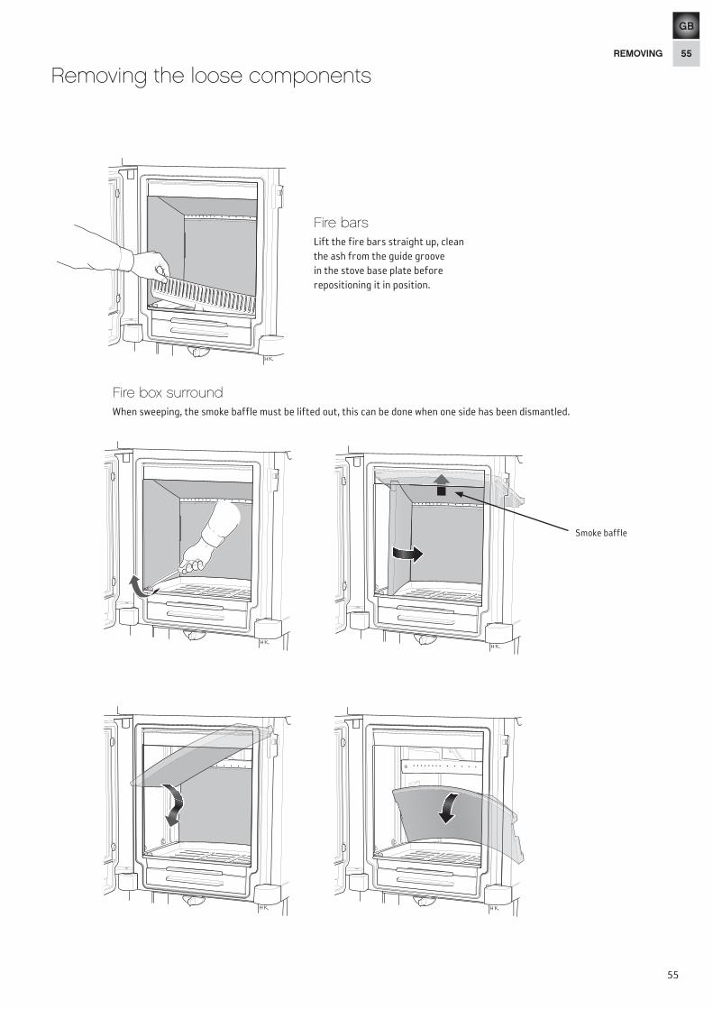
Removing the loose components
Fire barsLift the fire bars straight up, clean the ash from the guide groove in the stove base plate before repositioning it in position.
Fire box surroundWhen sweeping, the smoke baffle must be lifted out, this can be done when one side has been dismantled.
Smoke baffle
REMOVING

56
GB
56
Stove base plateThe stove base plate is lifted out when all the cladding has been removed.
Fixed or removable handleThe stove handle is fitted on delivery. To make the handle removable, replace the screw for the lock hook with the shorter screw supplied.
REMOVING

57
GB
57
Supply of combustion air
Combustion air can be provided directly via a duct from outside, or indirectly via a vent in the outer wall of the room where the stove is to be placed. The amount of combustion air used for combustion is approximately 25 m3/h.
Some installation alternatives are shown to the right. On certain models, C54 and C54T, when supply air is retrieved via walls behind, there is a knock out for inserting the combustion air hose, see figure below.
The air duct connection on the stove has an external diameter of Ø64 mm.
In hot areas the duct should be insulated with 30 mm mineral wool covered with a moisture inhibitor (plastic). It is important that the lead-in between the pipe and the wall (or floor) is sealed using jointing compound. When duct routing for further than 1 m the pipe diameter must be increased to 100 mm and a correspondingly larger wall vent must be selected.
A 1 m length of condensation insulated ducting for combustion air is available as an accessory.
HK
HK
HK
HK
30 m
m
Cover forC51, C52, C52T and 53Ducting to cover the outdoor air connection hose is available (accessory). The duct can be installed after the stove is installed.
Knock out on C54 and C54TTo insert the combustion air hose, the knockout in the base is tapped out using a hammer, remember to protect the floor.
COMBUSTION AIR

58
GB
58
Adjusting and connecting
Preparations before rear connectionThe stove is prepared for top connection on delivery. When connecting from the rear, the cover and connection must be swapped around.
• Dismantlethecladdingasinstructedpreviously,seepage 55.• Tapouttheknockoutinthestove’sbackpanel,rememberto
protect the floor.
• Thenunscrewboththeconnectorandthecover.
• Switchplacesandreinstallthescrews.
Contura 51
Adjusting the stove• Positionthestoveonthehearthplate.
• Uninstalltherearsectionsofthelegs.
• Adjusttheheightofthefouradjustablefeetuntil the stove is horizontal.
• Whentherearsectionshavebeenreinstalled, cover the screws with the plastic plugs supplied.
ADJUSTING AND CONNECTING

59
GB
59
Adjusting and connecting
Preparations before rear connectionThe stove is prepared for top connection on delivery. When connecting from the rear, the cover and connection must be swapped around.
• Dismantlethecladdingasinstructedpreviously,seepage55.• Tapouttheknockoutinthestove’sbackpanel,rememberto
protect the floor. • Thenunscrewboththeconnectorandthecover.• Switchplacesandreinstallthescrews.
Contura 52 / 52T
Adjusting the stove• Positionthestoveonthehearth
plate.
• Uninstalltheinnercoversofthelegs.
• Adjusttheheightofthefouradjustable feet until the stove is horizontal.
• Whentheinnersectionshavebeen reinstalled, cover the screws with the plastic plugs supplied.
ADJUSTING AND CONNECTING

60
GB
60
Soapstone installation Contura 52T
Handle soapstone with care, the edges are susceptible to damage. Soapstone is most easily cleaned using a cloth dampened with acetone.
• Removetheuppersecuringplate.
• Positionwiththedecorativegroovedownwardsothat the turned up edge holds the soapstone in place.
• Installandsecuretheuppersecuringplatesothat panel edge locks the soapstone.
• Dothesameontheoppositesideandthenposition the soapstone cap.
• Whenconnectingfrombehind,positionthecoverprovided over the hole for the top connection.
A hotplate is available as an accessory for installation in the hole in the top plate.
Continue with the section ”Connecting to the chimney” on page 64.
ADJUSTING AND CONNECTING

61
GB
61
Adjusting and connecting
Preparations before rear connectionThe stove is prepared for top connection on delivery. When connecting from the rear, the cover and connection must be swapped around.
• Dismantlethecladdingasinstructedpreviously,seepage55.
• Tapouttheknockoutinthestove’sbackpanel,remembertoprotectthefloor.
• Thenunscrewboththeconnectorandthecover.
• Switchplacesandreinstallthescrews.
Contura 53
Adjusting the stove• Positionthestoveonthehearthplate.
• Uninstalltherearsectionsofthelegs.
• Adjusttheheightofthefouradjustablefeetuntilthestove is horizontal.
• Whentherearsectionshavebeenreinstalled,coverthe screws with the plastic plugs supplied.
50
Continue with the section ”Connecting to the chimney” on page 64.
ADJUSTING AND CONNECTING
62
GB
62
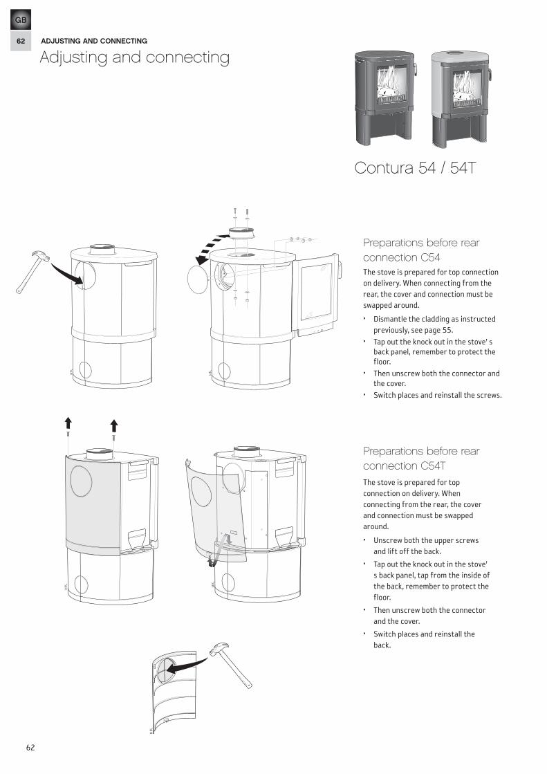
Adjusting and connecting
Preparations before rear connection C54The stove is prepared for top connection on delivery. When connecting from the rear, the cover and connection must be swapped around.
• Dismantlethecladdingasinstructed previously, see page 55.
• Tapouttheknockoutinthestove’sback panel, remember to protect the floor.
• Thenunscrewboththeconnectorandthe cover.
• Switchplacesandreinstallthescrews.
Contura 54 / 54T
Preparations before rear connection C54TThe stove is prepared for top connection on delivery. When connecting from the rear, the cover and connection must be swapped around.
• Unscrewboththeupperscrewsand lift off the back.
• Tapouttheknockoutinthestove’s back panel, tap from the inside of the back, remember to protect the floor.
• Thenunscrewboththeconnectorand the cover.
• Switchplacesandreinstalltheback.
ADJUSTING AND CONNECTING
63
GB
63
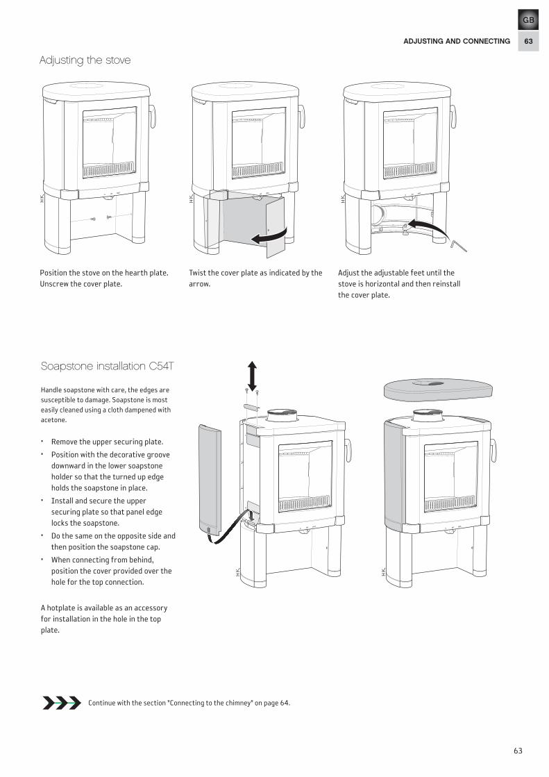
Adjusting the stove
Soapstone installation C54T
Handle soapstone with care, the edges are susceptible to damage. Soapstone is most easily cleaned using a cloth dampened with acetone.
• Removetheuppersecuringplate.
• Positionwiththedecorativegroovedownward in the lower soapstone holder so that the turned up edge holds the soapstone in place.
• Installandsecuretheuppersecuring plate so that panel edge locks the soapstone.
• Dothesameontheoppositesideandthen position the soapstone cap.
• Whenconnectingfrombehind,position the cover provided over the hole for the top connection.
A hotplate is available as an accessory for installation in the hole in the top plate.
Continue with the section ”Connecting to the chimney” on page 64.
Position the stove on the hearth plate. Unscrewthecoverplate.
Twist the cover plate as indicated by the arrow.
Adjust the adjustable feet until the stove is horizontal and then reinstall the cover plate.
ADJUSTING AND CONNECTING

64
GB
64
Connection to the chimney
After the stove has been adjusted and positioned according to the installation distances, connection to the chimney is carried out. Select one of the following alternatives.
Top connection to the steel fluePress the start pipe onto the connection, continue the chimney installation according to the chimney installation instructions.
LEK
Mark out centre for making a hole in the wall to the flue. Check that the connection height in the chimney breast corresponds to the height of the connection pipe from the stove.
Cut a hole approximately 180 mm in diameter.
Then cement in a wall connector with fire proof mortar (not supplied). Let the mortar dry before the stove is connected to the chimney.
Rearwards to a masonry chimneyConnection to a masonry chimney can be the back or the top of the stove.
Install the connection pipe on the connection. Make sure that the gasket does not work loose from its position. Caulk between the connection pipe and the connector in the wall using caulking rope. If further sealing material is required, heat-resistant sealant may be used.
Important!
Maximum chimney weight loading on the stove 120 kg.
NIBE AB · Box 134 · SE-285 23 Markaryd · Swedenwww.contura.eu
Contura reserves the right to change colours, materials, dimensions and models at any time without special notice. Your dealer can give you the most up to date information. Stoves shown in brochures may have optional extras.
CONNECTION THE CHIMNEY
811100 IAV SE-EX C50-22012-10-08