810 DX™ Pipe and Cable Locator OPERATIONS · PDF file810 DX™ Pipe and Cable...
36
810 DX™ Pipe and Cable Locator SERVICE CENTER, SALES AND TECHNICAL SUPPORT INFORMATION Warranty: One year. Specifications Subject to change without notice, ISO 9001:2000 Certified. Copyright 2008. All Rights Reserved. Rev 9/9/08 OPERATIONS MANUAL Vivax-Metrotech Corporation 3251 Olcott Street, Santa Clara, CA 95054, USA Website : www.vivax-metrotech.com Sales & Sales Support: T/Free : +1-800-446-3392 Tel : +1-408-734-1400 Fax : +1-408-734-1415 Email : [email protected] Application Support: T/Free : +1-800-624-6210 Tel : +1-408-454-7159 Fax : +1-408-743-5597 Email : [email protected] Service & Repairs: T/Free : +1-800-638-7682 Tel : +1-408-962-9990 Fax : +1-408-734-1799 Email : [email protected] All Other Department: T/Free : +1-877-330-1647 Tel : +1-408-734-3880 Fax : +1-408-962-9993 Australasia SebaKMT AUS Unit 1, 176 South Creek Road, Cromer NSW 2009, Australia Tel : +61-2-9972-9244 Fax : +61-2-9972-9433 Website : www.sebakmtaus.com Email : [email protected] [email protected] Leidi Utility Supply (Shanghai) Ltd. Rm405 3rd Building No. 641, Tianshan Rd, Shanghai, China 200336 Tel : +86-21-5187-3880 Fax : +86-21-5168-5880 Website : www.leidi.com Email : [email protected] CanadaVivax Canada Inc. 400 Esna Park Drive, Unit 17, Markham, Ontario, L3R 3K2, Canada Tel : +1-289-846-3010 Website : www.vivax-metrotech.com Email : [email protected] EuropeSebaKMT Seba Dynatronic Mess-und Ortungstechnik GmbH Dr.-Herbert-Iann-Str. 6, 96148 Baunach, Germany. Tel : +49-9544-680 Fax : +49-9544-2273 Website : www.sebakmt.com Email : [email protected]
Transcript of 810 DX™ Pipe and Cable Locator OPERATIONS · PDF file810 DX™ Pipe and Cable...

810 DX™ Pipe and Cable Locator
SERVICE CENTER, SALES AND TECHNICAL SUPPORT INFORMATION
Warranty: One year. Specifications Subject to change without notice, ISO 9001:2000 Certified. Copyright 2008. All Rights Reserved. Rev 9/9/08
OPERATIONS MANUAL
Vivax-Metrotech Corporation3251 Olcott Street,Santa Clara, CA 95054, USAWebsite : www.vivax-metrotech.comSales & Sales Support:T/Free : +1-800-446-3392Tel : +1-408-734-1400Fax : +1-408-734-1415Email : [email protected]
Application Support:T/Free : +1-800-624-6210Tel : +1-408-454-7159Fax : +1-408-743-5597Email : [email protected]
Service & Repairs:T/Free : +1-800-638-7682Tel : +1-408-962-9990Fax : +1-408-734-1799Email : [email protected]
All Other Department:T/Free : +1-877-330-1647Tel : +1-408-734-3880Fax : +1-408-962-9993
Australasia SebaKMT AUSUnit 1, 176 South Creek Road,Cromer NSW 2009, AustraliaTel : +61-2-9972-9244Fax : +61-2-9972-9433Website : www.sebakmtaus.comEmail : [email protected] [email protected]
Leidi Utility Supply (Shanghai) Ltd.Rm405 3rd Building No. 641, Tianshan Rd,Shanghai, China 200336Tel : +86-21-5187-3880Fax : +86-21-5168-5880Website : www.leidi.comEmail : [email protected]
CanadaVivax Canada Inc. 400 Esna Park Drive,Unit 17, Markham,Ontario, L3R 3K2, CanadaTel : +1-289-846-3010Website : www.vivax-metrotech.comEmail : [email protected]
EuropeSebaKMTSeba DynatronicMess-und Ortungstechnik GmbHDr.-Herbert-Iann-Str. 6,96148 Baunach, Germany.Tel : +49-9544-680Fax : +49-9544-2273Website : www.sebakmt.comEmail : [email protected]

810DX 9/9/2008 REV D 2
ISO 9001:2000 CERTIFIED
Metrotech has received ISO 9001:2001 Quality Management System Certification. Metrotech adheres to the quality standard guidelines of ISO 9001:2001 and ensures quality in its design/development, production, installation, and servicing disciplines. © Metrotech Corporation 2008 Metrotech Corporation 3251 Olcott Street, Santa Clara, CA 95054 Tel: 1.800.446.3392; 1.408.734.1400 Fax: 1.408.734.1415 E-mail: [email protected] Internet: www.metrotech.com Revision D, 9/9/08

810DX 9/9/2008 REV D 3
TABLE OF CONTENTS List of Illustrations………………………………………….4 1 Introduction ………………………………………………6 2 Safety Precautions………………………………………6 3 810DX Quick Start Guide for the Experienced User………………………………………..6 4 Model 810Dx Equipment………………………………..7 4.1 810Dx-D Standard Equipment…………………….7 4.2 810Dx-R Standard Equipment……………………..8 4.3 Accessories………………………………………….9 4.4 Technical Specifications…………………………..10 4.5 Transmitter: Controls Indicators, and Features …………………………..11 4.6 Receiver: Control, Indicators, and Features……………………………………………..14 5 Checkout Procedure…………………………………….17 6 Operation………………………………………………….18 6.1 Transmitter Set-up………………………………….18 6.2 Receiver Operation……………………..…………..21 7 Advanced Locating Techniques ………………………25 7.1 Ground Survey………………………………………25 7.2 Adjacent Utilities..…………………………………...26 7.3 Deep Utility…………………………………………..27 7.4 Tracing Long Runs………………………………….27 7.5 Locating a Service Lateral…………………………27 7.6 Locating a Bend or Dead End……………………..27 7.7 Valves, Manhole Cover, T’s and Risers…………………………………………………27 7.8 Common Bonded Utilities………………………….28 7.9 Congested Areas……………………………………29 7.10 Determining If You Have a “Ghost”
Utility………………………………………………….30 7.11 Pipes with Insulated Junctions…………………….30 7.12 Distribution Systems………………………………..30 7.13 Non-Metallic Pipes………………………………….30 7.14 Tracer Wire………………………………………….30 8 Maintenance……………………………………………..30 8.1 Replacing the 810Dx D-Cell
Transmitter Batteries……………………………….31 8.2 Replacing the 810Dx NiMH Transmitter Rechargeable Battery………………………………31 8.3 Recharging the 810Dx NiMH Transmitter Rechargeable Battery………………………………31 8.4 Service Center Information………………………..34

810DX 9/9/2008 REV D 4
Appendix………………………………………………………35 Copyright Notice……………………………………………..35 Warranty……………………………………………………….36 List of Illustrations Figure 4-1: Model 810Dx™ Pipe and Cable Locator - Standard Equipment…………………….……..7 Figure 4-2: Model 810Dx™ Pipe and Cable Locator with NiMH Transmitter Batteries……………….8 Figure 4-3: 810Dx Transmitter: Controls and Indicators……………………………………………….12 Figure 4-4: 810Dx Transmitter: Utility Line Resistance Chart……………………….…………….13 Figure 4-5: 810Dx Receiver: Controls and Indicators……………………………………………….14 Figure 4-6: 810Dx Receiver LCD Display………………15 Figure 4-7: 810Dx Receiver LCD Display: Depth Mode……………….…………………………………15 Figure 5-1: Connect Transmitter Leads..………………17 Figure 5-2: Aim Receiver at Transmitter………………18 Figure 6-1: Direct (Conductive) Connection….………19 Figure 6-2: Inductive Coupling with the MetroClamp………………………………….…………….…20 Figure 6-3: Transmitter Position for Inductive Tracing……………………………………………21 Figure 6-4: Receiver Position for Tracing……………..22 Figure 6-5: Receiver Position When Determining Depth………………………………………….23 Figure 6-6: Principle of Triangulation…………………..23 Figure 6-7: Receiver Position for Triangulation………24 Figure 6-8: Locate Centerline………...……….. ……….. 24 Figure 6-9: Multiple Utilities in a Common Trench…………………………….. 25 Figure 7-1: Blind Search Parallel Pattern………………26

810DX 9/9/2008 REV D 5
Figure 7-2: Adjacent Utilities - Position of Ground Lead…………………………………………….. 27 Figure 7-3: Locating Service Laterals…………………. 28 Figure 7-4: Locating a Bend…………………………….. 28 Figure 7-5: Locating a Dead End……………………….. 28 Figure 7-6: Incorrect Coupling for Congested Area…………………………………………….. 29 Figure 7-7: Correct Coupling for Congested Area…………………………………………….. 29 Figure 8-1: Replacing the D-Cell Transmitter Batteries……………………………………….31 Figure 8-2: Replacing the D-Cell batteries with the NiMH battery pack…………………… 31 Figure 8-3: Recharging the NiMH battery pack with the Wall Mount Charger…………….. 31 Figure 8-4: Recharging the NiMH battery pack and operating from an external 12-volt DC supply……………………………………………32 Figure 8-5: Replacing the 810Dx Receiver Batteries………………………………………….. 33 1 INTRODUCTION
810DX 9/9/2008 REV D 6
This manual describes the Metrotech Model 810Dx™ Pipe and Cable Locator. Included is an equipment description, product specifications, checkout procedures, operating procedures, application information and maintenance instructions. The Model 810Dx is a state-of-the-art pipe and cable locator precisely designed with many powerful features to provide you with optimum information about your locate situation. 2 SAFETY PRECAUTIONS 1 Metrotech pipe and cable locators are intended for use by utility and contractor
professionals. Safety hazards for underground utility access areas include electrical shock, explosive gases, and toxic fumes as well as potential influence on communications and control systems such as traffic control and railroad crossings.
2 Familiarize yourself with all required safety practices of the local utility company, or other
owner of the plant before entering an access area or connecting a Metrotech transmitter. 3 Before connecting the transmitter directly to any utility, make sure that the line is de-
energized and out of service. Never make a direct connection to a live power cable. 4 If you use the MetroClamp on energized electrical or control lines follow appropriate
safety procedures to avoid the risk of injury. 5 Pay special attention when using a locator in high traffic areas. 3 810Dx QUICK START GUIDE FOR THE EXPERIENCED USER 1 Check Batteries – Turn Transmitter ON. If the battery status is low (less than 25%)
replace or recharge the battery. 2 Connect Transmitter to Utility - Turn Transmitter “OFF”. Plug the Conductive
Attachment into Transmitter. Stretch black lead 90 degrees away from utility. Press ground rod into the earth. Clamp black lead to grounding rod. Clamp red lead to target utility. Turn Transmitter “ON”.
3 Adjust Receiver Controls - Turn Receiver “ON”.
4 Sweep Area Around Transmitter – Circle Transmitter with Receiver at a distance of 10 feet (3 m). Left/Right display and Receiver signal strength will indicate location of buried utilities.
5 Locate Line - Follow your target utility, sweeping left and right as you walk away from the Transmitter. Mark the centerline on the ground.
6 Measure Depth - Hold the Receiver over the centerline and press the depth button. The LCD will display the depth in feet and inches.
4 MODEL 810Dx™ EQUIPMENT

810DX 9/9/2008 REV D 7
4.1 810Dx-D Standard Equipment (Alkaline Transmitter Batteries) Part # Description 10293 Receiver 83kHz 10294 Transmitter 83kHz 800B004 Conductive Attachment Direct Connect Assembly Ground Rod 10826 Hard Carrying Case 10943 Operation Manual Figure 4-1: Model 810Dx™ Pipe and Cable Locator - Standard Equipment
1. 810Dx Receiver 2. 810Dx Transmitter 3. Conductive Attachment 4. Ground Rod 5. Operation manual 6. Carrying Case
4.2 810Dx-R Standard Equipment (NiMH Transmitter Batteries)

810DX 9/9/2008 REV D 8
Part # Description 10293 Receiver 83kHz 10874 Transmitter 83kHz w/ NiMH Batteries 10793 Wall Mount Charger 800B004 Conductive Attachment Direct Connect Assembly Ground Rod 10826 Hard Carrying Case 10943 Operation Manual Notice: Please contact factory for wall mount chargers versions outside of USA and Canada.
Figure 4-2: Model 810Dx™ Pipe and Cable Locator with NiMH Transmitter Batteries
1. 810Dx Receiver 2. 810Dx Transmitter 3. Conductive Attachment 4. Ground Rod 5. Operation Manual 6. Carrying Case 7. Wall Mount Charger
4.3 Accessories

810DX 9/9/2008 REV D 9
Part/Model # Description Remarks 4290 2” MetroClamp For Inductive Coupling 4490 4” MetroClamp For Inductive Coupling 4890 8” MetroClamp For Inductive Coupling 400B246 Conductive Attachment Telephone style Clips 400A132 100’ Ground Lead Extension 10873 12-volt DC power lead For use with external power source e.g.
Vehicle cigarette lighter and transmitter battery recharging. 10126 Live Power Connector 4.4 Technical Specifications
810DX 9/9/2008 REV D 10
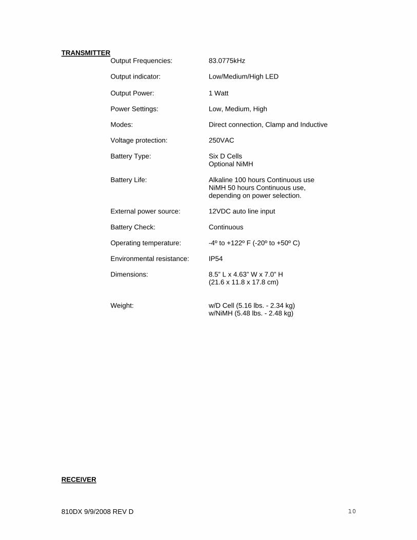
TRANSMITTER Output Frequencies: 83.0775kHz Output indicator: Low/Medium/High LED Output Power: 1 Watt Power Settings: Low, Medium, High Modes: Direct connection, Clamp and Inductive Voltage protection: 250VAC Battery Type: Six D Cells Optional NiMH Battery Life: Alkaline 100 hours Continuous use NiMH 50 hours Continuous use,
depending on power selection. External power source: 12VDC auto line input
Battery Check: Continuous
Operating temperature: -4º to +122º F (-20º to +50º C) Environmental resistance: IP54
Dimensions: 8.5” L x 4.63” W x 7.0” H (21.6 x 11.8 x 17.8 cm) Weight: w/D Cell (5.16 lbs. - 2.34 kg) w/NiMH (5.48 lbs. - 2.48 kg) RECEIVER

810DX 9/9/2008 REV D 11
Receiving frequency: 83.0775kHz Depth Accuracy: 0-10’ +/-(5% + 2”) under normal conditions 10’-20’ +/-(10% +2”) under normal conditions Features: Distance Sensitive Left/Right GuidanceTM Real-Time Continuous Gain Adjustment TM
Push Button Depth Backlighting standard Serial link RS232 Battery Type: Eight AA Alkaline Cells Battery Life: 85 hours continuous use 75 hours continuous backlit use Battery Check: Continuous Automatic Operation Temperature: -4º to +122º F (-20º to +50º C) Environmental resistance: IP54 Dimensions: 28.7” L x 8.63” W x 12.25” H (72.9 x 21.9 x 31.1 cm) Weight: (4.14 lbs.- 1.88 kg.) 4.5 Transmitter: Controls, Indicators, and Features 4.5.1 Transmitter Controls and Indicators - See Figure 4-2 for the location of the controls and indicators described below: Output Jack - Insert the Direct Connect cable or the MetroClamp cable into this jack. (Located under the connection cover of the Transmitter). Inductive Position – Place the transmitter over your targeted utility as shown on the label of the transmitter. External Power/Charger Jack- The transmitter can be powered by external 12VDC supply e.g. from vehicle battery by connection to the external/charger jack. Connection of the external supply switches off internal batteries. The same jack connects the wall mount charger to charge rechargeable batteries. If standard alkaline batteries are used no charging takes place. Battery Door – The battery door is removed by rotating the ring latch. Slide the lid of the battery door to gain access to the batteries. Observe battery polarity, which is indicated on the label inside the battery compartment.
810DX 9/9/2008 REV D 12
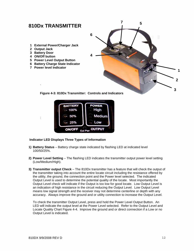
810Dx TRANSMITTER
1 External Power/Charger Jack 2 Output Jack 3 Battery Door 4 ON/Off button 5 Power Level Output Button 6 Battery Charge State Indicator 7 Power level Indicator
` Figure 4-3: 810Dx Transmitter: Controls and Indicators
:
Indicator LED Displays Three Types of Information
1) Battery Status – Battery charge state indicated by flashing LED at indicated level
100/50/25%. 2) Power Level Setting – The flashing LED indicates the transmitter output power level setting
(Low/Medium/High). 3) Transmitter output Check – The 810Dx transmitter has a feature that will check the output of
the transmitter taking into account the entire locate circuit including the resistance offered by the utility, the ground, the connection point and the Power level selected. The indicated Output Level is used to determine the potential quality of the locate. Most importantly the Output Level check will indicate if the Output is too low for good locate. Low Output Level is an indication of high resistance in the circuit reducing the Output Level. Low Output Level means low signal strength and the receiver may not determine centerline or depth with any accuracy. Always improve the ground and or utility connection to increase the Output Level.
To check the transmitter Output Level, press and hold the Power Level Output Button. An
LED will indicate the output level at the Power Level selected. Refer to the Output Level and Locate Quality Chart Figure 4-4. Improve the ground and or direct connection if a Low or no Output Level is indicated.
2
4
7
6
1
3
5

810DX 9/9/2008 REV D 13
Power level Selector – Change level by pressing power output level selector. Press once to decrease from HIGH to MEDIUM, MEDIUM LED now flashing. Press again to decrease from MEDIUM to LOW, LOW LED now flashing. Press again to return to HIGH power Power Setting HIGH 1.0 Watts MEDIUM 0.5 Watts LOW 0.2 Watts
Figure 4-4: 810Dx Output level and locate quality chart 4.5.2 Transmitter Features Automatic Impedance Matching - Automatically matches the Transmitter to the line impedance to provide maximum output in direct mode. Output Level Indicator - Provides information on the locate quality in the three power level modes. Please see Fig. 4-4 Standard Alkaline D cells or Rechargeable Batteries – Battery compartment can accommodate standard D cell alkaline batteries or Metrotech supplied NiMH battery pack. Smart charging circuit™ automatically detects presence of Alkaline or NiMH battery pack. Battery level Indicator – Indicates battery charge status. Inductive Antenna - Provides locating capability where direct connect or Metroclamp utility access is not available. Multiple Power Levels - Provides maximum flexibility for all locating jobs from high congestion to long distance tracing.
Utility Line Locate Quality Check
Output Power Selection Indicated Output Locate Quality
High Excellent
Medium Good
Low Poor High
None Improve Connection
Medium Excellent
Low Good Medium
None Improve Connection
Low Good Low
None Improve Connection

810DX 9/9/2008 REV D 14
810Dx RECEIVER
Figure 4-5: 810Dx Receiver - Controls and Indicators
4.6 Receiver: Controls and Indicators
4.6.1 Receiver Controls and Indicators See Figure 4-5 for the location of the controls and indicators described below:
ON/OFF Depth button - Turn ON by a quick press of the ON/OFF DEPTH button. Turn OFF by extended press (3 seconds) on ON/OFF DEPTH button. Take depth reading by quickly pressing the ON/OFF DEPTH button.
Button – Press once to turn the backlight on. Press once to turn the backlight off.
Volume UP/DOWN buttons – Change speaker volume by pressing UP button or DOWN button.Receiver emits tone at new volume level.
Battery Charge Status
Operating Frequency
Signal Strength
Distance SensitiveLeft/Right Guidance
Backlight
Volume up/down arrows On/Off Depth Button

810DX 9/9/2008 REV D 15
Receiver DISPLAY (Liquid Crystal Display) - Displays the battery status, operating frequency, Distance Sensitive Left/Right Guidance™, and signal strength.
1 Battery Status 2 Operating Frequency 3 Distance Sensitive Left/Right Guidance 4 Signal Strength
Figure 4-6: 810Dx Receiver Display
The receiver displays depth estimation in feet and inches or centimeters.
Figure 4-7: 810Dx Receiver LCD Display: Depth Mode
1 2
3
4
Depth Button
810DX 9/9/2008 REV D 16
SPEAKER - Emits audio tone to guide operator toward the targeted utility.
BATTERY COMPARTMENT – To open, turn spring-loaded quarter-turn latch counter clockwise to release battery compartment door. Separate battery compartment from receiver housing, slide cover and gain access to the batteries. To open the battery compartment door, turn the spring-loaded quarter and separate the compartment door by gently pulling on the latch. N AUTO/MAN 4.6.2 Receiver Features Distance Sensitive Left/Right Guidance™ -Provides visual and audible direction and distance information guiding you to the target utility. Battery Charge Status - Continuously displays remaining battery charge status provides flashing low power alert. Depth Button - Provides quick depth estimation in feet and inches (or in cm). Real-Time Continuous Gain Adjustment™ - Automatic gain continuously optimizes the sensitivity of the Receiver eliminating the need for manual gain adjustment. Simultaneous Peak and Null Display™ - Provides signal strength and centerline simultaneously for fast productive locating. Battery Saving Automatic Power Down - After five minutes of no activity, the Receiver turns off to save battery life. Depth Measurement to 20 Feet (6 m) - Depth measurement range is up to 20 feet (6 m). RS232 Serial Communication Port - Provides data transfer capability for calibration and service.

810DX 9/9/2008 REV D 17
5 CHECKOUT PROCEDURE For proper operation of the Model 810Dx Pipe and Cable Locator, use this checkout procedure: • upon receiving the equipment • before each job, preferably before you leave for the site • if problems arise during a locate 1 Place transmitter on the ground. Plug conductive attachment leads into the Transmitter, and attach them to one another. As shown in Figure: 5-1 2 Turn the Transmitter “ON”. Check the output power level setting is at high, indicated by a
flashing LED. Note battery charge status. If charge is low, replace or recharge Transmitter batteries.
3 Perform output check by pressing the output power level button continuously. The
flashing LED will change to a constant LED at high, confirming Transmitter and Conductive Attachment is in good working condition.
4 Turn the Receiver “ON”. Slowly swing the Receiver side to side while pointing it at the transmitter. The Distance Sensitive Left/Right GuidanceTM System display should respond. The signal strength should also respond to the movement and be at its highest when pointed directly at the transmitter. See Figure 5-2.
Figure 5-1: Connect Transmitter Leads
810DX 9/9/2008 REV D 18
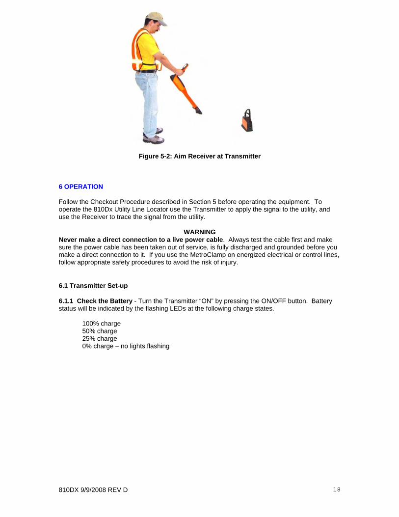
Figure 5-2: Aim Receiver at Transmitter 6 OPERATION Follow the Checkout Procedure described in Section 5 before operating the equipment. To operate the 810Dx Utility Line Locator use the Transmitter to apply the signal to the utility, and use the Receiver to trace the signal from the utility.
WARNING Never make a direct connection to a live power cable. Always test the cable first and make sure the power cable has been taken out of service, is fully discharged and grounded before you make a direct connection to it. If you use the MetroClamp on energized electrical or control lines, follow appropriate safety procedures to avoid the risk of injury. 6.1 Transmitter Set-up 6.1.1 Check the Battery - Turn the Transmitter “ON” by pressing the ON/OFF button. Battery status will be indicated by the flashing LEDs at the following charge states. 100% charge 50% charge 25% charge 0% charge – no lights flashing

810DX 9/9/2008 REV D 19
6.1.2 Methods of Applying Signal to a Utility - The three methods of applying the signal to the utility are - Direct Connect, Inductive Coupling, and Inductive. Following is a description of each method and instruction of use. A Direct (Conductive) Connection - This is the preferred mode of operation because the transmitter is connected directly to a metallic part of the utility (hydrant, meter, riser, valves, sheath, and tracer wire), allowing maximum signal to reach the utility. In this operating mode the Receiver can be closer to the Transmitter, and adjacent buried utility interference is reduced. 1 Insert the Conductive Attachment - Turn the Transmitter off. Insert the Direct Connect
Cable into the OUTPUT JACK on the Transmitter. 2 Set up and connect to a ground - Extend the BLACK lead of the Direct Connect Cable at a right angle as far as possible from the utility. Press the ground spike into the ground as far as possible, then attach the black clip. If the ground spike cannot be used, connect to appropriate ground using an extension reel. Look for a convenient existing ground, such as a metal street sign. Be careful not to get close to or cross any adjacent buried utility. If no existing ground is available, use the ground spike. Drive the ground spike as far into the ground as possible, and attach the BLACK lead. See Figure 6-1. 3 Connect to your utility - Connect the RED lead of the Direct Connect Cable to the
targeted utility. Make sure of good metal to metal contact.
Figure 6-1: Direct (Conductive) Connection
4 Turn Transmitter ON – Press ON/OFF button to turn Transmitter ON. Transmitter comes on in High power mode.
5 Select Transmitter output power – The 810Dx Transmitter has three output power
settings – HIGH, MEDIUM, and LOW
810DX 9/9/2008 REV D 20
Transmitter Output Setting High 1.0 Watts Medium 0.5 Watts Low 0.2 Watts Decrease output power by pressing the OUTPUT button. Press once to decrease from
HIGH to MEDIUM, MEDIUM LED now flashing. Press again to decrease from MEDIUM to LOW power. Press again to return to HIGH power.
6 Transmitter Output Check – Pressing power output level button continuously checks the
locate quality of the targeted utility. A constant LED represents output current is applied to the targeted utility. If the high power level is selected and the LED is on high, it means maximum output current is on the targeted utility line. If no LED is indicated, regardless of the power level selected, improve connection. Improving your ground connection and/or the quality of the direct connection, can reduce the amount of resistance in the circuit and improve the output current on the target utility. Wetting the area around the ground rod will increase the output current.
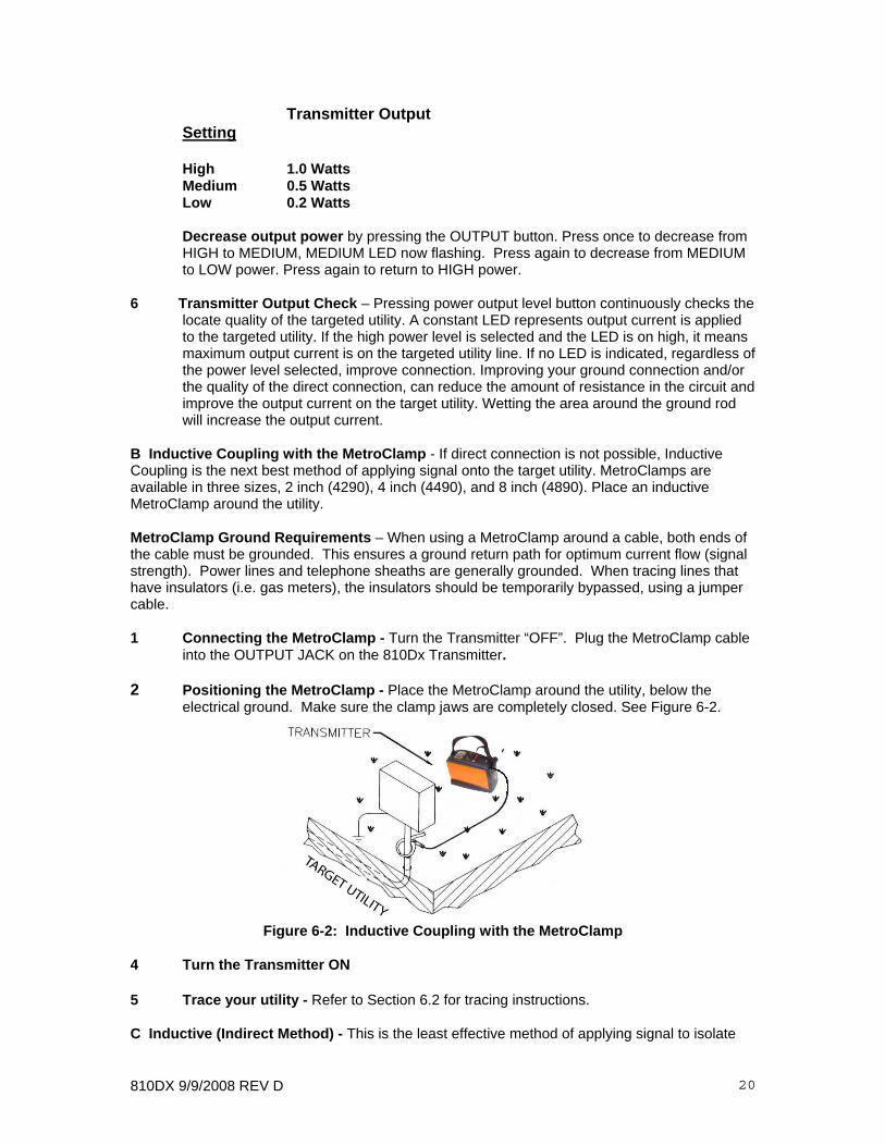
B Inductive Coupling with the MetroClamp - If direct connection is not possible, Inductive Coupling is the next best method of applying signal onto the target utility. MetroClamps are available in three sizes, 2 inch (4290), 4 inch (4490), and 8 inch (4890). Place an inductive MetroClamp around the utility. MetroClamp Ground Requirements – When using a MetroClamp around a cable, both ends of the cable must be grounded. This ensures a ground return path for optimum current flow (signal strength). Power lines and telephone sheaths are generally grounded. When tracing lines that have insulators (i.e. gas meters), the insulators should be temporarily bypassed, using a jumper cable. 1 Connecting the MetroClamp - Turn the Transmitter “OFF”. Plug the MetroClamp cable
into the OUTPUT JACK on the 810Dx Transmitter. 2 Positioning the MetroClamp - Place the MetroClamp around the utility, below the
electrical ground. Make sure the clamp jaws are completely closed. See Figure 6-2.
Figure 6-2: Inductive Coupling with the MetroClamp
4 Turn the Transmitter ON 5 Trace your utility - Refer to Section 6.2 for tracing instructions. C Inductive (Indirect Method) - This is the least effective method of applying signal to isolate

810DX 9/9/2008 REV D 21
one utility. The signal is broadcast in all directions and can couple to every nearby utility through electromagnetic induction. It is possible to reduce the broadcasting signal by pressing the power output level button to change the power level from high to medium or medium to low. The transmitter induction antenna will be “ON” when there is no plug in the output jack. Sometimes it is not possible to gain access to the pipe or cable to make a direct connection or to use the MetroClamp. In these cases use the Transmitter’s internal antenna. Three power levels can be selected when the Transmitter is “ON”, it will broadcast the signal from the internal antenna. No ground connection is needed when a signal is induced onto the target utility. 1 Position the Transmitter - Remove any cable or clamp plug from the OUTPUT JACK. Position the Transmitter across the buried utility as indicated on Figure 6-3.
Figure 6-3: Transmitter Position for Inductive Tracing
2 Turn the Transmitter ON. 4 Tracing the utility - Refer to Section 6.2 6.2 Receiver Operation - When tracing a utility, always be alert to surrounding conditions which could interfere with the accuracy of your locate. Adjacent utilities pull the signal away from the target utility and can be misleading in both position and depth of the utility. Periodically sweep to each side of the utility to check for the presence of other utilities. The Receiver Left/Right Guidance System will indicate a second centerline, or will behave erratically if there is signal interference. 6.2.1 Receiver Set-up 1 Turn the Receiver ”ON” - Turn Receiver ON with quick press of ON/OFF DEPTH
button. 2 Check Battery Charge - The amount of battery charge will appear in the battery symbol
in the upper left corner of the Receiver LCD. Replace the batteries if the symbol does not have any bars. See Section 8.3 for battery replacement.
3 Sweep the area - Hold the Receiver at a comfortable angle and make a 360-degree
sweep 8 to 10 feet (2.5 to 3 m) around the connection point. During this sweep, stop at each centerline, note the signal strength. To do this, make sure the signal strength is below ”999”. Position the Receiver over the centerline and press the ON/OFF DEPTH button.
4 Check for air coupling (Inductive mode only) - When using the inductive method,

810DX 9/9/2008 REV D 22
make sure the Receiver is not air coupled to the Transmitter. This can occur from 8 to 50 feet (2.5 to 15 m) from the Transmitter. To determine air coupling, find a centerline and lift the Receiver straight up. If the signal strength decreases smoothly, the receiver is not air coupled. If the signal strength stays the same, or increases, the receiver is air coupled. Move further away from or switch to a lower power setting on the Transmitter until the receiver is no longer air coupling.
5 Trace the path of the utility - Hold the 810Dx Receiver at a comfortable angle. See
Figure 6-4. Move it from side to side keeping the antenna as parallel to the ground as possible.
Figure 6-4: Receiver Position for Tracing
The following features guide to the target utility:
A) Distance Sensitive Left/Right GuidanceTM - is a visual guide to the target utility. When the bar is to the left, move to the left. When the bar is to the right, move to the right. When centered over the utility, the vertical bar will be centered between the arrows.
B) Audible Tone – is an audible guide to the utility. When the tone is pulsing move
to the left. When the tone is steady, move to the right. When centered over the utility, there is no tone (NULL).
C) Signal Strength the numerical signal strength should be the highest when over
the target utility. 6 Mark the target utility path - When the utility’s location is confirmed, mark it as required.
See Appendix for APWA color markings. 7 If signal strength drops - If the signal strength drops suddenly and the Left/Right
Guidance is not present, the utility may have changed direction. If this happens, sweep the area to find the centerline and take a depth reading. If the depth and signal strength change, but Left/Right Guidance remains the same, the utility may have changed depth. If it has remained steady, continue on.
8 To activate the backlighting feature – Simply press Backlight button once to turn ON.
Press button once to turn OFF. 9 Turn the Transmitter and Receiver off – Turn off Transmitter by pressing the ON/OFF
810DX 9/9/2008 REV D 23
button for 3 seconds. Turn Receiver OFF by pressing the ON/OFF DEPTH button for 3 seconds. Disconnect the accessories when you have finished your locate.
6.2.2 Determining the Depth of a Utility - The depth of a utility may be determined in any of
the Transmitter hook-up modes. When determining depth in the Inductive Mode, move at least 35 feet (12 m) from the Transmitter to prevent air coupling with the transmitter signal. Signal strength must be greater than 250 for a depth estimation.
Keep in mind that any number of variables; including soil conditions, overhead lines, adjacent utilities, and the utility material may affect depth measurements. Most water and gas pipes are deeper than CATV and telephone cable. Use the depth measurement as a verification that you are still on your target utility.
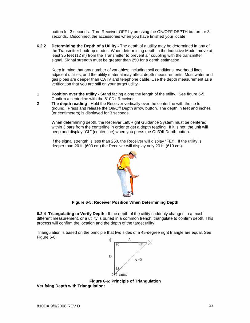
1 Position over the utility - Stand facing along the length of the utility. See figure 6-5.
Confirm a centerline with the 810Dx Receiver. 2 The depth reading - Hold the Receiver vertically over the centerline with the tip to
ground. Press and release the On/Off Depth arrow button. The depth in feet and inches (or centimeters) is displayed for 3 seconds.
When determining depth, the Receiver Left/Right Guidance System must be centered within 3 bars from the centerline in order to get a depth reading. If it is not, the unit will beep and display “CL” (center line) when you press the On/Off Depth button.
If the signal strength is less than 250, the Receiver will display “FEr”. If the utility is
deeper than 20 ft. (600 cm) the Receiver will display only 20 ft. (610 cm).
Figure 6-5: Receiver Position When Determining Depth
6.2.4 Triangulating to Verify Depth - If the depth of the utility suddenly changes to a much different measurement, or a utility is buried in a common trench, triangulate to confirm depth. This process will confirm the location and the depth of the target utility. Triangulation is based on the principle that two sides of a 45-degree right triangle are equal. See Figure 6-6.
Figure 6-6: Principle of Triangulation Verifying Depth with Triangulation:

810DX 9/9/2008 REV D 24
1 Centerline and record the depth by pressing the ON/OFF depth button. Mark the centerline
2 Tilt the Receiver away from the utility at a 45-degree angle – Touch the horizontal
antenna to the ground while the tip of the receiver on the ground 3 Move away from the utility - The Left/Right Guidance System will indicate another
centerline. Mark this spot on the ground. See Figure 6-8.
4 Repeat this process on the opposite side of the utilities. 5 Calculate depth - One half the distance between the two centerlines is the approximate
depth of your utility. NOTE: The Left/Right sensors are used in the triangulation method.
Figure 6-7: Receiver Position for Triangulation
Figure 6-8: Locate Centerline 6.2.5 Triangulation for Confirming Presence of Common Trench Utilities - If locating a
utility in a common trench, the signal may induce onto a more shallow or more

810DX 9/9/2008 REV D 25
conductive utility.
Use triangulation to confirm the presence and depth of multiple utilities. Find the depth of the first utility and then continue to move away from the utility, marking each utility depth. Repeat the process to the other side and then calculate the depth of each utility. See figure 6-9.
Figure 6-9: Multiple Utilities in a Common Trench 7 ADVANCED TECHNIQUES 7.1 Ground Survey - Regulations at construction sites often require a ground survey before any excavation is done. This prevents damaging underground utilities. A ground survey is a process to locate all the underground utilities within a particular area. It includes standard locating and a blind search. A blind search is a search for utilities with unknown sources and endings. The 810Dx must be operated in the Inductive Mode using a systematic grid approach. 7.1.1 Locating Utilities - First use one of the three modes of operation (Direct Connect most accurate) to locate the known utilities and mark their location on the ground. Follow the procedures outlined in Section 6. 7.1.2 Blind Search - Two operators are required for a blind search. One carries the Transmitter, the other operates the Receiver. Starting approximately 35 feet (12 m) apart, the two operators
CATV
Gas
Water
__ 12”
36”
__ 60”
__
810DX 9/9/2008 REV D 26
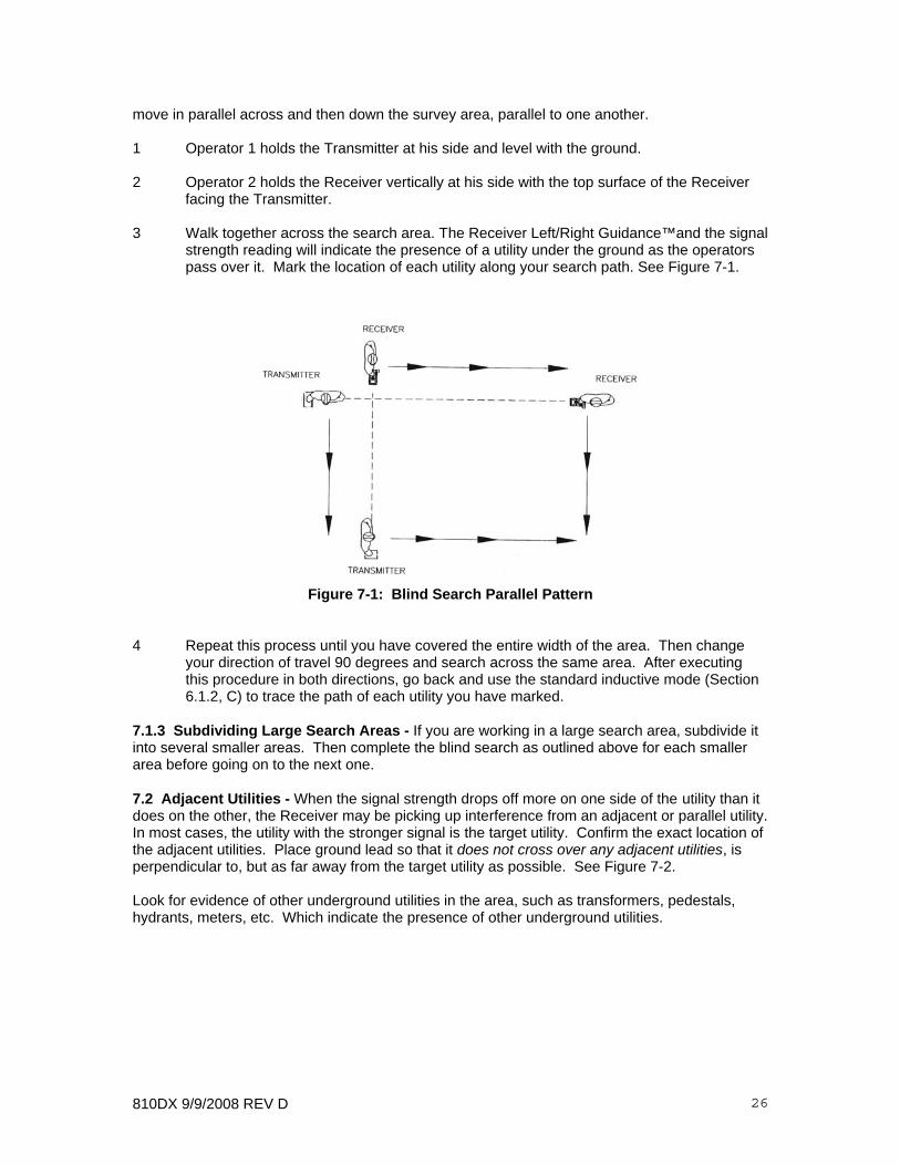
move in parallel across and then down the survey area, parallel to one another. 1 Operator 1 holds the Transmitter at his side and level with the ground. 2 Operator 2 holds the Receiver vertically at his side with the top surface of the Receiver facing the Transmitter. 3 Walk together across the search area. The Receiver Left/Right Guidance™and the signal
strength reading will indicate the presence of a utility under the ground as the operators pass over it. Mark the location of each utility along your search path. See Figure 7-1.
Figure 7-1: Blind Search Parallel Pattern
4 Repeat this process until you have covered the entire width of the area. Then change your direction of travel 90 degrees and search across the same area. After executing this procedure in both directions, go back and use the standard inductive mode (Section 6.1.2, C) to trace the path of each utility you have marked.
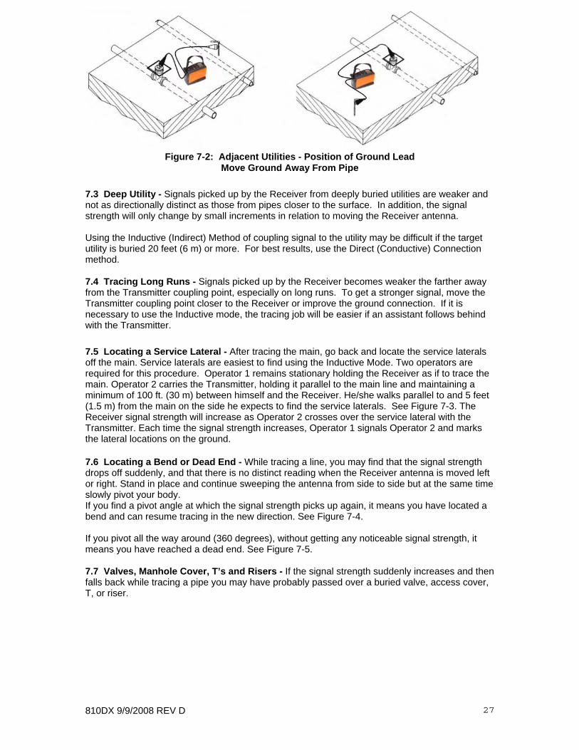
7.1.3 Subdividing Large Search Areas - If you are working in a large search area, subdivide it into several smaller areas. Then complete the blind search as outlined above for each smaller area before going on to the next one. 7.2 Adjacent Utilities - When the signal strength drops off more on one side of the utility than it does on the other, the Receiver may be picking up interference from an adjacent or parallel utility. In most cases, the utility with the stronger signal is the target utility. Confirm the exact location of the adjacent utilities. Place ground lead so that it does not cross over any adjacent utilities, is perpendicular to, but as far away from the target utility as possible. See Figure 7-2. Look for evidence of other underground utilities in the area, such as transformers, pedestals, hydrants, meters, etc. Which indicate the presence of other underground utilities.
810DX 9/9/2008 REV D 27
Figure 7-2: Adjacent Utilities - Position of Ground Lead Move Ground Away From Pipe
7.3 Deep Utility - Signals picked up by the Receiver from deeply buried utilities are weaker and not as directionally distinct as those from pipes closer to the surface. In addition, the signal strength will only change by small increments in relation to moving the Receiver antenna. Using the Inductive (Indirect) Method of coupling signal to the utility may be difficult if the target utility is buried 20 feet (6 m) or more. For best results, use the Direct (Conductive) Connection method. 7.4 Tracing Long Runs - Signals picked up by the Receiver becomes weaker the farther away from the Transmitter coupling point, especially on long runs. To get a stronger signal, move the Transmitter coupling point closer to the Receiver or improve the ground connection. If it is necessary to use the Inductive mode, the tracing job will be easier if an assistant follows behind with the Transmitter. 7.5 Locating a Service Lateral - After tracing the main, go back and locate the service laterals off the main. Service laterals are easiest to find using the Inductive Mode. Two operators are required for this procedure. Operator 1 remains stationary holding the Receiver as if to trace the main. Operator 2 carries the Transmitter, holding it parallel to the main line and maintaining a minimum of 100 ft. (30 m) between himself and the Receiver. He/she walks parallel to and 5 feet (1.5 m) from the main on the side he expects to find the service laterals. See Figure 7-3. The Receiver signal strength will increase as Operator 2 crosses over the service lateral with the Transmitter. Each time the signal strength increases, Operator 1 signals Operator 2 and marks the lateral locations on the ground. 7.6 Locating a Bend or Dead End - While tracing a line, you may find that the signal strength drops off suddenly, and that there is no distinct reading when the Receiver antenna is moved left or right. Stand in place and continue sweeping the antenna from side to side but at the same time slowly pivot your body. If you find a pivot angle at which the signal strength picks up again, it means you have located a bend and can resume tracing in the new direction. See Figure 7-4. If you pivot all the way around (360 degrees), without getting any noticeable signal strength, it means you have reached a dead end. See Figure 7-5. 7.7 Valves, Manhole Cover, T’s and Risers - If the signal strength suddenly increases and then falls back while tracing a pipe you may have probably passed over a buried valve, access cover, T, or riser.

810DX 9/9/2008 REV D 28
Figure 7-3: Locating Service Laterals
Figure 7-4: Locating a Bend
Figure 7-5: Locating a Dead End 7.8 Common Bonded Utilities - Telephone, power, and CATV sometimes use a common ground bond. If other utilities are connected to your target utility, putting a signal on the target can cause all the utilities to carry the same signal, making it difficult to identify the target utility. To verify that you are tracing the targeted utilities, note the field strength at a known location of the utility. As you trace, any change in field strength should be gradual. If either reading changes abruptly you are probably no longer over your targeted utility. NOTE: This method will work only if there is no cross bonding on the length of the utility between

810DX 9/9/2008 REV D 29
the utility and the Receiver. 7.10 Congested Areas - If you suspect that coupling from adjacent utilities is causing interference in the signal picked up by the Receiver, try increasing the strength of the signal on your utility and decreasing the strength of signal from the interfering utilities by: 1 Changing to a different transmitter coupling point or coupling mode. Try another
approach. Move the Transmitter so you are locating from a less congested area into the congested area. See Figures 7-6 and 7-7.
2 Improving the ground connection or moving the grounding point. 3 Determine the location of the adjacent utilities. Then check to be sure that neither the
direct connect cable or the ground cable cross over any of the adjacent utilities. Reposition them if necessary.
4 If you are inducing, you can decrease the interfering signal by changing the position of
the Transmitter. Find the location of the interfering utility. Stand the Transmitter on its end (vertically) over the interfering utility. This will reduce or eliminate signal on this line.
Figure 7-6: Incorrect Coupling for Congested Area
Figure 7-7: Correct Coupling for Congested area
7.11 Determining If You Have a “Ghost” Utility - If there is another utility near your target

810DX 9/9/2008 REV D 30
utility, it too may pick up signal from the Transmitter. When this occurs, there will seem to be a ”ghost” between the two utilities. You are likely to have a ”ghost” trace if any of the following phenomena occur: 1 The Left/Right Guidance™ bar moves in the same direction you move the Receiver.
(Normally the Left/Right moves in the opposite direction.) 2 The signal strength drops as you move toward the ”ghost” utility. 3 When you take a press button depth reading, indicated depth is illogical, or no depth at
all. The Receiver reads a ”ghost” utility when each Left/Right antenna coil receives an equal amount of signal from two separate utilities. The location of the ”ghost” may vary according to the soil conditions and the size, depth, and conductivity of adjacent utilities. Use one of the methods for improving your signal as given in Section 7.10, Congested Areas. 7.12 Pipes with Insulated Junctions - The high 82kHz radio frequency signal will cross pipe insulators, however, the signal will decrease proportionately each time it crosses an insulator. When possible, such as when tracing a pipe with a meter, bypass the meter (insulator) by using a jumper cable. Attach each end of the jumper cable on opposite sides of the insulator. 7.13 Distribution Systems - To locate short gas services on a gas distribution system, you should temporarily ground the end of the service. This can be accomplished by temporarily connecting a jumper cable to a ground spike at the end of a service, where the pipe or tracer wire comes out of the earth. Be sure to remove the ground connection after completing the locate so as not to defeat the cathodic protection system. 7.14 Non-Metallic Pipes - To trace nonmetallic pipe (sewer line) or duct, send the signal through the pipe by inserting the appropriate 83kHz Metrotech Sonde. For accurate depth readings with Sonde, refer to the sonde depth table to convert indicated depth to actual sonde depth. An alternative method is to insert a snake or fishtape into the pipe and connect the Direct Connect Cable from the Transmitter to one end of it. See section 6.2.1,11. 7.15 Tracer Wire - When using tracer wire to trace nonmetallic pipe, keep in mind that the far end of the tracer wire must be grounded. This provides a return path for the signal. 8 MAINTENANCE The only routine maintenance required for the equipment and accessories is to test and recharge or replace, if necessary, the batteries in the Transmitter and the Receiver. Both possess battery test features, making it easy to check the condition of the batteries at any time. The 810Dx is designed for rugged outdoor use, but rough handling should be avoided. Keep the equipment dry, clean, and free of grit. Store the 810Dx (in its carrying case) in a cool, dry place. Do not expose to excessive temperatures. We recommend checking the Transmitter and Receiver batteries before each use, preferably before leaving for the job site. 8.1 Replacing the 810Dx Alkaline D-Cell Transmitter Batteries - See Figure 8-1.
810DX 9/9/2008 REV D 31
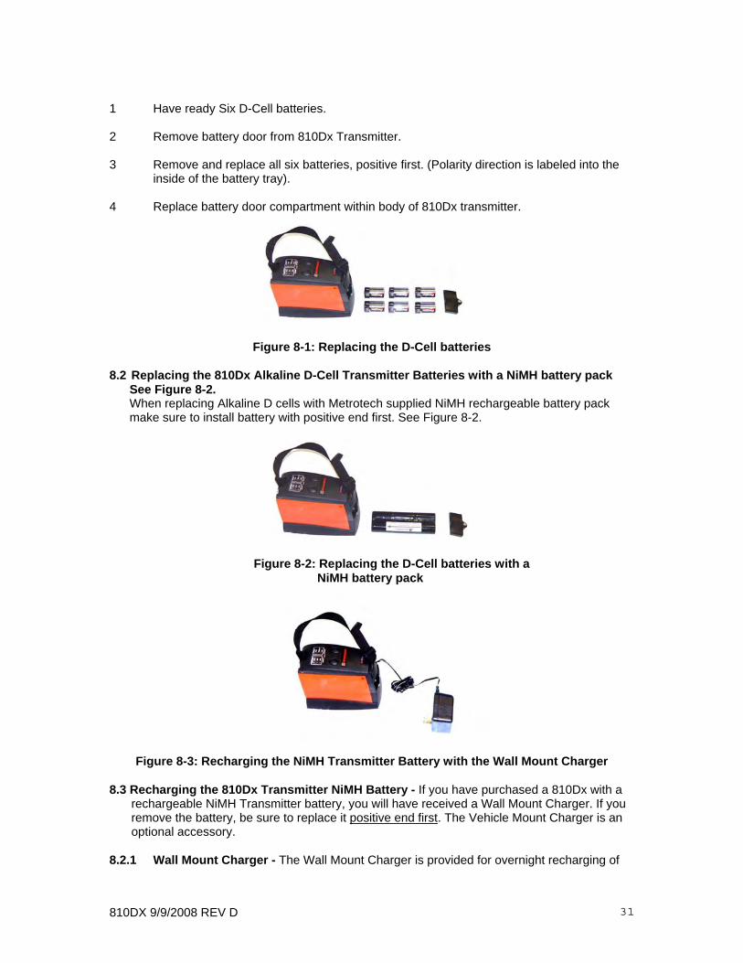
1 Have ready Six D-Cell batteries. 2 Remove battery door from 810Dx Transmitter. 3 Remove and replace all six batteries, positive first. (Polarity direction is labeled into the
inside of the battery tray). 4 Replace battery door compartment within body of 810Dx transmitter.
Figure 8-1: Replacing the D-Cell batteries
8.2 Replacing the 810Dx Alkaline D-Cell Transmitter Batteries with a NiMH battery pack See Figure 8-2. When replacing Alkaline D cells with Metrotech supplied NiMH rechargeable battery pack make sure to install battery with positive end first. See Figure 8-2.
Figure 8-2: Replacing the D-Cell batteries with a NiMH battery pack
Figure 8-3: Recharging the NiMH Transmitter Battery with the Wall Mount Charger
8.3 Recharging the 810Dx Transmitter NiMH Battery - If you have purchased a 810Dx with a rechargeable NiMH Transmitter battery, you will have received a Wall Mount Charger. If you remove the battery, be sure to replace it positive end first. The Vehicle Mount Charger is an optional accessory.
8.2.1 Wall Mount Charger - The Wall Mount Charger is provided for overnight recharging of
810DX 9/9/2008 REV D 32
your rechargeable NiMH Transmitter battery. Allow 12-14 hours to fully recharge your rechargeable NiMH Transmitter battery. See Figure 8-2.
1 Turn the Transmitter ”OFF”. 2 Plug the Wall Mount cube into a 3-prong 120V socket. (Contact Metrotech for charger
versions specific to the country where operating equipment). 3 Insert the wall mount 2.5 mm plug into the EXTERNAL POWER/CHARGER JACK on the
outside wall of the Transmitter. The charging LED on the end of the Transmitter body will light. Leave overnight.
5 To check the amount of Transmitter charge, unplug the wall mount from the Transmitter
and turn the Transmitter ON. The battery charge state will be indicated by the flashing LED at 100/50/25 %.
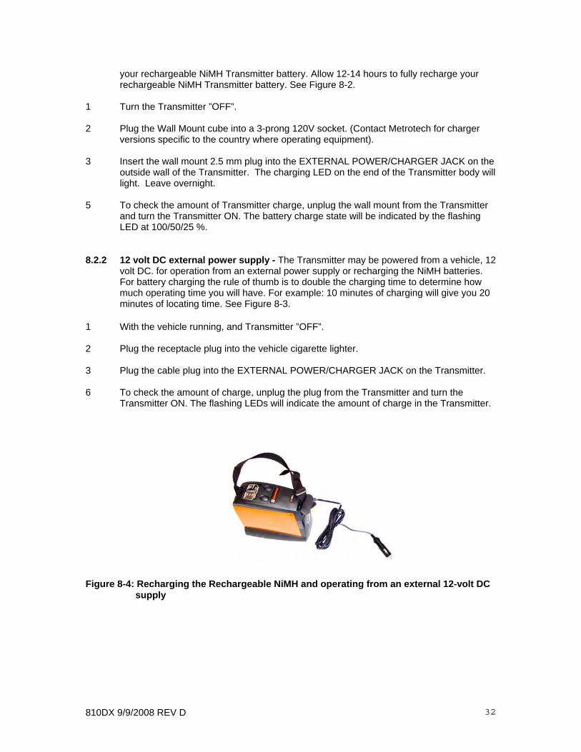
8.2.2 12 volt DC external power supply - The Transmitter may be powered from a vehicle, 12 volt DC. for operation from an external power supply or recharging the NiMH batteries. For battery charging the rule of thumb is to double the charging time to determine how much operating time you will have. For example: 10 minutes of charging will give you 20 minutes of locating time. See Figure 8-3.
1 With the vehicle running, and Transmitter ”OFF”. 2 Plug the receptacle plug into the vehicle cigarette lighter. 3 Plug the cable plug into the EXTERNAL POWER/CHARGER JACK on the Transmitter. 6 To check the amount of charge, unplug the plug from the Transmitter and turn the
Transmitter ON. The flashing LEDs will indicate the amount of charge in the Transmitter.
Figure 8-4: Recharging the Rechargeable NiMH and operating from an external 12-volt DC supply

810DX 9/9/2008 REV D 33
Figure 8-5: Replacing the 810Dx Receiver Batteries
8.3 Replacing the 810Dx Receiver Batteries - See Figure 8-4.
1 Have ready eight AA batteries. 2 Turn the spring-loaded quarter-turn latch on the underside of the 810Dx.Receiver body
and remove the battery compartment.
3 Carefully pull the battery compartment out of the unit. Slide the battery compartment cover to gain access to the batteries.
4 Always remove all of the batteries before replacing any of them to avoid confusion as to
which are fresh and which are depleted.
5 Replace batteries following polarity marked on inside of battery compartment.
6 Slide battery compartment cover back into position in the battery compartment.
7 Replace battery compartment in body of Receiver. Turn spring-loaded quarter turn latch to lock battery compartment in place.

810DX 9/9/2008 REV D 34
Check the instruments batteries before contacting Metrotech Services.
8.4 Service Center Information – Should the instrument require service, please contact a Metrotech Customer Service Department:
For a Repair Service request form, go to www.metrotech.com/techsupport.asp. Download and print the Repair Service request form. Fill the requested information and place the form in the case. If you have any questions about your unit, please call the Metrotech's service center where the unit was sent.
Additional Metrotech Instruments: Pipe and Cable Locators, Ferromagnetic Locators, Fiber Optic Cable Locating System, Sheath Fault Locators, Acoustic Water Leak Detectors, Electronic Marker Locators.
Vivax-Metrotech Corporation3251 Olcott Street,Santa Clara, CA 95054, USAWebsite : www.vivax-metrotech.comSales & Sales Support:T/Free : +1-800-446-3392Tel : +1-408-734-1400Fax : +1-408-734-1415Email : [email protected]
Application Support:T/Free : +1-800-624-6210Tel : +1-408-454-7159Fax : +1-408-743-5597Email : [email protected]
Service & Repairs:T/Free : +1-800-638-7682Tel : +1-408-962-9990Fax : +1-408-734-1799Email : [email protected]
All Other Department:T/Free : +1-877-330-1647Tel : +1-408-734-3880Fax : +1-408-962-9993
CanadaVivax Canada Inc. 400 Esna Park Drive,Unit 17, Markham,Ontario, L3R 3K2, CanadaTel : +1-289-846-3010Website : www.vivax-metrotech.comEmail : [email protected]
EuropeSebaKMTSeba DynatronicMess-und Ortungstechnik GmbHDr.-Herbert-Iann-Str. 6,96148 Baunach, Germany.Tel : +49-9544-680Fax : +49-9544-2273Website : www.sebakmt.comEmail : [email protected]
Australasia SebaKMT AUSUnit 1, 176 South Creek Road,Cromer NSW 2009, AustraliaTel : +61-2-9972-9244Fax : +61-2-9972-9433Website : www.sebakmtaus.comEmail : [email protected] [email protected]
Leidi Utility Supply (Shanghai) Ltd.Rm405 3rd Building No. 641, Tianshan Rd,Shanghai, China 200336Tel : +86-21-5187-3880Fax : +86-21-5168-5880Website : www.leidi.comEmail : [email protected]

810DX 9/9/2008 REV D 35
APPENDIX A1 APWA Marking Colors - The following color markings have been established by the American Public Works Association (APWA): Utility Color Electric power lines, cables, or conduits Red Communication lines, cables, conduits, CATV Orange Gas, oil, petroleum, or other gaseous materials Yellow Sewers, storm and sanitary, drain lines Green Water, irrigation, or slurry lines Blue Note: If you have any questions regarding marking requirements or procedures in the United States, please call you local One Call Center. International customers: please check with your local regulatory authorities or utility companies required color markings may vary between different countries.
COPYRIGHT NOTICE The information contained in this document is for informational purposes only and is subject to change without notice. Metrotech Corporation makes no warranty of any kind with regard to the information contained in this manual, including but not limited to the implied warranties of merchantability and fitness for a particular purpose. Metrotech shall not be liable for errors contained herein, nor for incidental or consequential damages from the furnishing of this information. This manual contains proprietary information that is protected by copyright. All rights are reserved. No part of this manual may be photocopied, reproduced, magnetically or electronically stored, transmitted, or translated into another language without the prior written consent of Metrotech Corporation. © Metrotech Corporation 2008

810DX 9/9/2008 REV D 36
WARRANTY
THERE ARE NO WARRANTIES, EXPRESSED OR IMPLIED, INCLUDING ANY WARRANTY OF MERCHANTABILITY, BEYOND THOSE STATED HEREIN.
Metrotech warrants its equipment to be free from defects in workmanship and material under normal and proper use and service for one year from date of purchase by original user. Metrotech assumes no obligation to repair or replace equipment which has been altered or repaired by other than a Metrotech-approved procedure, been subject to misuse, misapplication, improper maintenance, negligence, or accident; has had its serial number or any part thereof altered, defaced or removed; or been used with parts other than those approved by Metrotech. Warranty does not include batteries. Expendable items such as fuses and lamps are excluded.
Any detection product proved defective under this warranty will be repaired or replaced free of charge at the Metrotech Corporation factory or approved Metrotech repair station. The equipment should be returned to our factory by prepaid transportation after requesting and receiving return authorization from our Customer Service Department. Metrotech’s obligations are limited to repair or replacement of broken or defective parts which have not been abused, misused, altered, or accidentally damaged, or at the option of Metrotech, to refund of the purchase price. Metrotech assumes no liability for removal or installation costs, consequential damages, or contingent expenses of any other nature.
Part#: 10943