802.3ba copper cable assembly baseline · PDF file100GBASE-CR10 baseline electrical...
27
1 802.3ba – July 2008 802.3ba copper cable assembly baseline proposal Chris Di Minico MC Communications [email protected]
Transcript of 802.3ba copper cable assembly baseline · PDF file100GBASE-CR10 baseline electrical...

1
802.3ba – July 2008
802.3ba copper cable
assembly baseline proposal
Chris Di Minico MC [email protected]

2
802.3ba – July 2008
Contributors
•Galen Fromm, Jay Neer - Molex•Jens Aumann, Leoni Special Cables•Vivek Telang, Broadcom•Howard Baumer, Mobius Semiconductor•Amir Mezer, Intel

3
802.3ba – July 2008
Supporters
•Dan Dove, ProCurve Networking by HP•Shimon Muller, Sun Microsystems•Tom Palkert, Luxtera•Gourgen Oganessyan, Quellan•Ed Cady, Meritec•Herb Van Deusen, Gore •Hugh Barrass, Cisco•ilango Ganga, Intel•Rich Mellitz, Intel•Greg McSorley, Amphenol•Bob Thornton, Fujitsu•Bill MacKillop, Cinch Connectors•Jim McGrath, Cinch Connectors
4
802.3ba – July 2008
Summary
•Considerations for 802.3ba Cu cable assembly specifications for 802.3ba baseline proposal.
•Measurement models and simulation models developed to validate usage of 10GBASE-KR (Clause 72) for 10 Gb/s lane options for both 40GBASE-CR4 and 100GBASE-CR10 cable assemblies.
•CX4 twinaxial cable assembly differential parameters proposed asbasis for 40GBASE-CR4 and 100GBASE-CR10 link specification (i.e., S-parameters).
•Considerations for configuring QSFP low speed electrical hardware pins for 40GBASE-CR4 operation.
•Two independent demonstrations of 10GBASE-KR operation over 10 meters of passive copper cable assemblies.

5
802.3ba – July 2008
• Support full-duplex operation only
• Preserve the 802.3 / Ethernet frame format utilizing the 802.3 MAC• Preserve minimum and maximum FrameSize of current 802.3 standard• Support a BER better than or equal to 10-12 at the MAC/PLS service
interface• Provide appropriate support for OTN
• Support a MAC data rate of 40 Gb/s• Provide Physical Layer specifications which support 40 Gb/s operation
over:– at least 10km on SMF
– at least 100m on OM3 MMF– at least 10m over a copper cable assembly– at least 1m over a backplane
• Support a MAC data rate of 100 Gb/s
• Provide Physical Layer specifications which support 100 Gb/s operation over:
– at least 40km on SMF– at least 10km on SMF– at least 100m on OM3 MMF
– at least 10m over a copper cable assembly
802.3ba objectives

6
802.3ba – July 2008
• Support a MAC data rate of 40 Gb/s• Provide Physical Layer specifications which support
40 Gb/s operation over:– at least 10m over a copper cable assembly– 4 x 10 Gb/s lane
• Support a MAC data rate of 100 Gb/s• Provide Physical Layer specifications which support
100 Gb/s operation over:– at least 10m over a copper cable assembly– 10 x 10 Gb/s lane
Copper cable assembly: lane options considered

7
802.3ba – July 2008
• Utilize 10GBASE-KR (Clause 72) and 10GBASE-CX4 to specify 40GBASE-CR4 and 100GBASE-CR10.
– 64B/66B PCS
– Signaling speed 10.3125 Gbd (per lane)
– 4x and 10x - KR transmit and receive functions
– Commonality with 40 GbE backplane proposal
– S-parameters - cable assembly differential parameter
– x4 MDI considered: QSFP and IEC 61076-3-113 mechanical mating interface (10GBASE-CX4 mechanical)
+ QSFP- module and connector dimensions common for both fiber and copper
� For 40GBASE-CR4, QSFP low speed control and sense signals set to non-operational QSFP state.
+ CX4 – connector mechanicals for copper (allows for backward compatibility)
- SFF-8092 MDI considered for 100GBASE-CR10: (proposals evaluated in IBTA)
• Optional FEC sublayer - PCS to interface to optional FEC sublayer - consider Clause 74 specification – commonality with 40 GbE backplane proposal
• Auto-Negotiation – consider Clause 73 specification - negotiate FEC capability through Auto-Negotiation
802.3ba Cu cable assembly proposal

8
802.3ba – July 2008
40GBASE-CR4 and 100GBASE-CR10 layer diagrams
LLC
MAC
Reconciliation
Medium
XLGMII
40GBASE- CR4
LLC
MAC
Reconciliation
Medium
CGMII
100GBASE- CR10
64B/66B PCS
Optional FEC
PMA
PMD
AN
64B/66B PCS
Optional FEC
PMA
PMD
AN
MDI MDI
9
802.3ba – July 2008
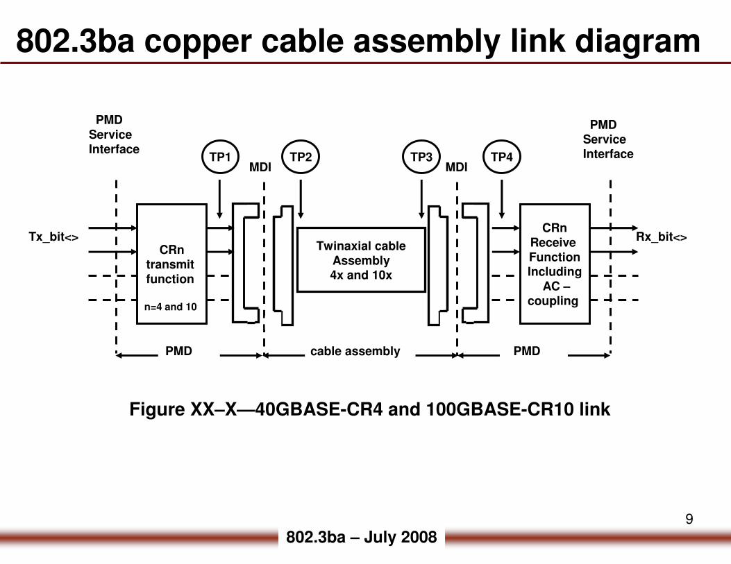
802.3ba copper cable assembly link diagram
MDI
Twinaxial cableAssembly4x and 10x
TP1 TP2 TP3 TP4
CRntransmit function
cable assembly
MDI
CRnReceive FunctionIncluding
AC –coupling
PMDPMD
PMDService Interface
PMDService Interface
Tx_bit<> Rx_bit<>
n=4 and 10
Figure XX–X—40GBASE-CR4 and 100GBASE-CR10 link

10
802.3ba – July 2008
dB
dB
dB
dB
dB
dB
Unit
TBD
TBD
TBD
TBD
TBD
TBD
ValueDescription
40GBASE-CR4 and 100GBASE-CR10 cable assembly
•Cable assembly differential parameters
f
TBDfTBDfTBDfLossInsertion +×+≤)(
TBDfReturnLoss ≥)(
×−≥
TBD
fTBDTBDfNextLoss log)(
×−≥
TBD
fTBDTBDfMDNextLoss log)(
×−≥
TBD
fTBDTBDfELFEXT log)(
×−≥
TBD
fTBDTBDfMDELFEXT log)(
•TBD’s > to be determined from measurement models.

11
802.3ba – July 2008
100GBASE-CR10 - MDI considered: SFF-8092
•SFF-8092 Specification for Mini Multilane Series: Shielded High Density Connector (mechanicals).
-Scope: The specification defines the plug, guide/strain relief shell, mating interface, footprint, and latching requirements.
-x12 proposals currently under consideration in IBTA EWG-QDR
•40GBASE-CR4 and 100GBASE-CR10 for cable assembly differential parameters.

12
802.3ba – July 2008
40GBASE-CR4 and 100GBASE-CR10 Auto-Neg
• Adopt Clause 73 (Auto-Negotiation) as a baseline for 40GBASE-CR4 and 100GBASE-CR10 with applicable changes for CR4 and CR10 operation.– Use Auto-Neg to Negotiate FEC capability– Auto-Neg allows backward compatibility with legacy 10 GbE
CX4 PHYs• Clause 73 provides parallel detection function for compatibility
with legacy PHYs that do not support Auto-Negotiation– New 40 GbE PHY can use parallel detection for auto-detection
of legacy CX4 devices– No impact to 10GBASE-CX4 devices
• See ganga_03_05_08.pdf (“FEC and Auto-Neg Proposal for 40/100G Copper Cable Assembly”)

13
802.3ba – July 2008
•� Proposed changes for 40GBASE-CR4 and 100GBASE-CR10–� Add Technology Ability bits from the reserved space to indicate
�� 40GBASE-CR4 ability�� 100GBASE-CR10 ability
–� Reuse AN management registers–� No change to negotiate FEC ability
�� FEC when selected to be enabled on all lanes�� FEC is enabled when both sides advertise FEC ability and at least one side requests to enable FEC
–� No change to Pause ability and Remote Fault bits–� Parallel detection function to detect legacy 10GBASE-CX4 PHYs
40GBASE-CR4 and 100GBASE-CR10 Auto-Neg
•See ganga_03_05_08.pdf (“FEC and Auto-Neg Proposal for 40/100G Copper Cable Assembly”)

14
802.3ba – July 2008
40GBASE-CR4 and 100GBASE-CR10 FEC
• Adopt Clause 74 FEC as baseline for an optional sublayer for 40GBASE-CR4 and 100GBASE-CR10 with appropriate changes for CR4 and CR10 operation. – Negotiate FEC capability through Auto-Negotiation– FEC is optional- allows lowering BER of 10-12 for integration into
systems which require lower BER– Correction of burst errors up to 11 bits
– 2-2.5 dB coding gain – No penalty in signaling rate
• Enumerate the FEC encode and decode functions for 4 lane and 10 lane operation– Each lane is encoded and decoded independently
– The coding is performed on a virtual lane basis– 4 in case of 40 Gb/s– 20 in case of 100 Gb/s
• Commonality with 40 Gb/s backplane solution
• Reuse the management register format
• See ganga_03_0508.pdf (“FEC and Auto-Neg Proposal for 40/100G Copper Cable Assembly”) for details• See http://www.ieee802.org/802_tutorials/july06/10GBASE-KR_FEC_Tutorial_1407.pdf for FEC tutorial

15
802.3ba – July 2008
3.1.1.4 ModPrsLModPrsL is pulled up to Vcc_Host on the host board and grounded in the module. The ModPrsL is asserted “Low” when inserted and deasserted “High” when the module is physically absent from the host connector.
3.1.1.5 IntLIntL is an output pin. When “Low”, it indicates a possible module operational fault or a status critical to the host system. The host identifies the source of the interrupt using the 2-wire serial interface. The IntL pin is an open collector output and must be pulled to host supply voltage on the host board.
•For 40GBASE-CR4 copper QSFP low speed control and sense signals set to non-operational QSFP state
QSFP Transceiver Specification Revision 1.0
module present
no module
copper module
Condition
ModPrsL set low, IntL either state
operational
x0
both signals open11
ModPrsl open,IntL set low
01
Signal stateIntLModPrsL
QSFP low speed electrical hardware pins
16
802.3ba – July 2008
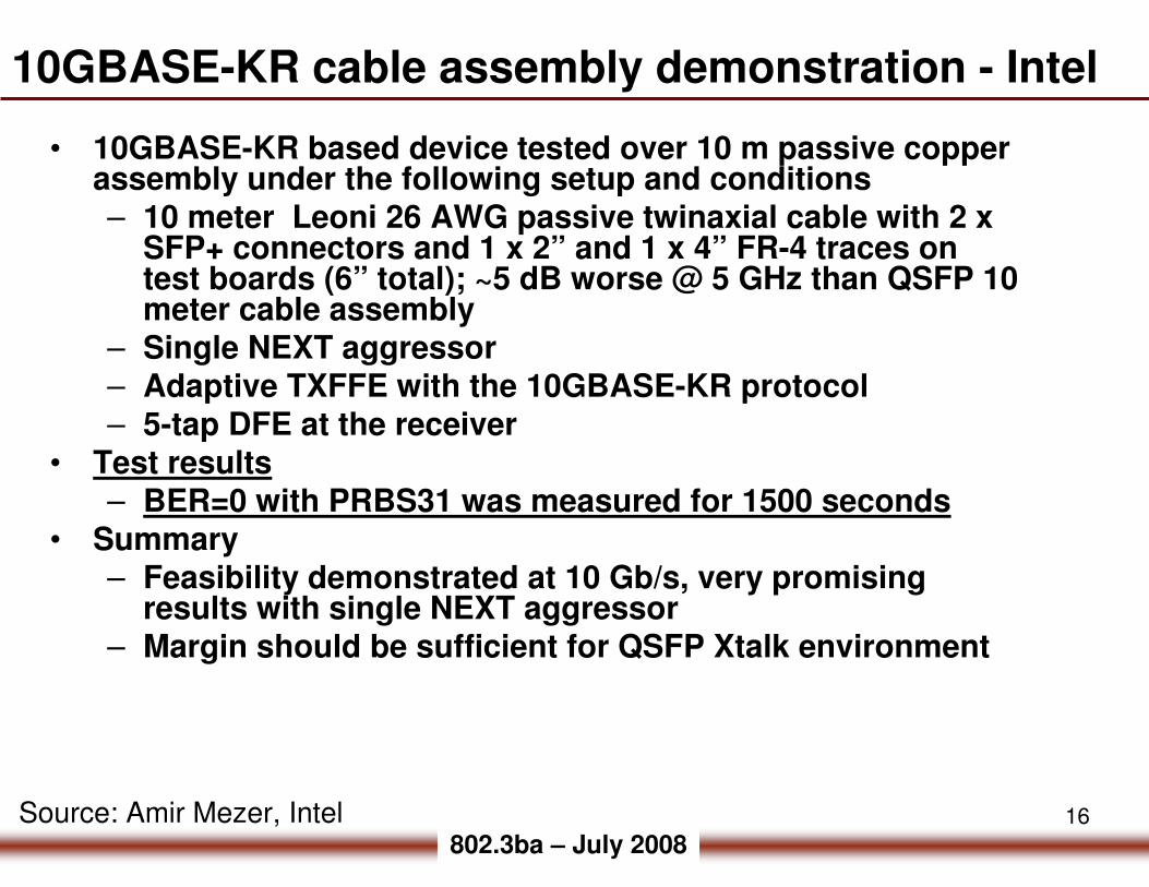
10GBASE-KR cable assembly demonstration - Intel
• 10GBASE-KR based device tested over 10 m passive copper assembly under the following setup and conditions– 10 meter Leoni 26 AWG passive twinaxial cable with 2 x
SFP+ connectors and 1 x 2” and 1 x 4” FR-4 traces on test boards (6” total); ~5 dB worse @ 5 GHz than QSFP 10 meter cable assembly
– Single NEXT aggressor– Adaptive TXFFE with the 10GBASE-KR protocol– 5-tap DFE at the receiver
• Test results– BER=0 with PRBS31 was measured for 1500 seconds
• Summary– Feasibility demonstrated at 10 Gb/s, very promising
results with single NEXT aggressor– Margin should be sufficient for QSFP Xtalk environment
Source: Amir Mezer, Intel
17
802.3ba – July 2008
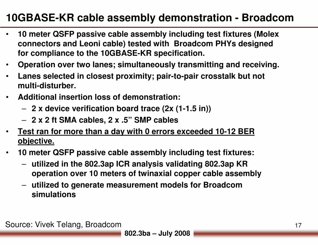
10GBASE-KR cable assembly demonstration - Broadcom
• 10 meter QSFP passive cable assembly including test fixtures (Molex
connectors and Leoni cable) tested with Broadcom PHYs designed for compliance to the 10GBASE-KR specification.
• Operation over two lanes; simultaneously transmitting and receiving.
• Lanes selected in closest proximity; pair-to-pair crosstalk but not multi-disturber.
• Additional insertion loss of demonstration:
– 2 x device verification board trace (2x (1-1.5 in))
– 2 x 2 ft SMA cables, 2 x .5” SMP cables
• Test ran for more than a day with 0 errors exceeded 10-12 BER objective.
• 10 meter QSFP passive cable assembly including test fixtures:
– utilized in the 802.3ap ICR analysis validating 802.3ap KR operation over 10 meters of twinaxial copper cable assembly
– utilized to generate measurement models for Broadcomsimulations
Source: Vivek Telang, Broadcom

18
802.3ba – July 2008
10GBASE-KR demonstration setup - Broadcom
Source: Vivek Telang, Broadcom

19
802.3ba – July 2008
40GBASE-CR4 and 100GBASE-CR10 baseline
• Adopt 10GBASE-KR electrical specifications (Clause 72) for 40GBASE-CR4 and 100GBASE-CR10 baseline electrical specifications with applicable revisions to account for differences in channel parameters e.g., copper cable assembly versus backplane and the 4-lane and 10-lane operation versus serial operation.
• Adopt 10GBASE-CX4 (Clause 54) cable assembly characteristic transmission parameters for 40GBASE-CR4 and 100GBASE-CR10 with TBD’s (slide 10) to be determined from measurement models utilized in the feasibility analysis with the additional consideration of specifying the PCB loss between the transmit function and TP1 and the PCB loss between the receiver function block and TP4 in Figure xx-x. TP2 will be used as test reference point for the transmit function which will include the additional specified PCB loss to be measured with the appropriate test fixture; nicholl_01_0708.pdf to be used as guidance on minimum PCB length. The channel parameters are expected to fall within the high confidence region as defined for 10GBASE-KR in 802.3ap Annex 69B.
• Adopt 40GBASE-CR4 (x4) MDI - QSFP and IEC 61076-3-113 mechanical mating interface (10GBASE-CX4 mechanical) and 100GBASE-CR10 MDI - SFF-8092 Specification for Mini Multilane Series: Shielded High Density Connector (mechanicals).
• Adopt Clause 73 (Auto-Negotiation) as a baseline for 40GBASE-CR4 and 100GBASE-CR10 with appropriate changes for CR4 and CR10 operation.
• Adopt Clause 74 FEC as baseline for an optional sublayer for 40GBASE-CR4 and 100GBASE-CR10 with appropriate changes for CR4 and CR10 operation.
20
802.3ba – July 2008
Backup

21
802.3ba – July 2008
Tx R2
TxRx
4 near- end crosstalk Disturbers
multi- disturber NEXT
Insertion loss,
Tx3 far- end crosstalk
disturbersmulti- disturber FEXT
Rx
+
802.3ap – channel parameter comparisons
•Insertion loss to crosstalk ratio (ICR) computed from S-parameter measurements and models of QSFP 10 meter copper cable assembly (24 AWG).

22
802.3ba – July 2008
802.3ap ICR limits vs 10 m QSFP cable assembly 24 AWG including test fixture
0
20
40
60
80
100
120
0 1000 2000 3000 4000 5000 6000
MHz
dB
ICRmin(f)
ICRfit(f)
ICR(f)
Tx1_IL-cable assembly+ pcb test fixture loss
PSNEXT(f)
PSFEXT_scaled
PSXT(f)
SDD12_NEXT_Tx1Rx1
SDD12_NEXT_Tx2Rx1
SDD12_NEXT_Tx3Rx1
SDD12_NEXT_Tx4Rx1
SDD12_FEXT_Tx1Rx2
10GBASE-KR
fmin=0.05 GHz
fmax=15.00 GHz
f1=1.00 GHz
f2=6.00 GHz
fa=0.100 GHz
fb=5.15625 GHz
802.3ap
A(f) max
attenuation
f1=1.00 GHz
f2=6.00 GHz
PSNEXT(f) - 4 disturbers
802.3ap ICRmin(f)
fa=.100 GHz
fb= 5.15625 GHz
802.3ap ICRfit(f)
fa=.100 GHz
fb= 5.15625 GHz
PSFEXT(f) - 3 disturbers
PSXT(f) - 4 NEXT + 3 FEXT
802.3ap recommends that
ICRfit(f)= ICRmin(f)
fa=0.100 to f2=5.15625 GHz

23
802.3ba – July 2008
802.3ap ICR limits vs 0.5 m QSFP cable assembly 24 AWG including test fixture
0
20
40
60
80
100
120
0 1000 2000 3000 4000 5000 6000
MHz
dB
Tx3_Rx3_IL_0.5m_IOL
ICRfit(f)
ICRmin(f)
ICR(f)-IOL-0.5 m
PSXT_0.5m_IOL
Tx1_Rx3_NE_.05 m_IOL
Tx2_Rx3_NE_.05 m_IOL
Tx3_Rx3_NE_.05 m_IOL
Tx4_Rx3_NE_.05 m_IOL
Tx1_Rx3_FE_.05 m_IOL
Tx2_Rx3_FE_.05 m_IOL
Tx4_Rx3_FE_.05 m_IOL
PSNEXT_10.5m_IOL
PSFEXT_0.5m_IOL
Measurement performed at UNH-IOL
802.3ap ICRmin
24
802.3ba – July 2008
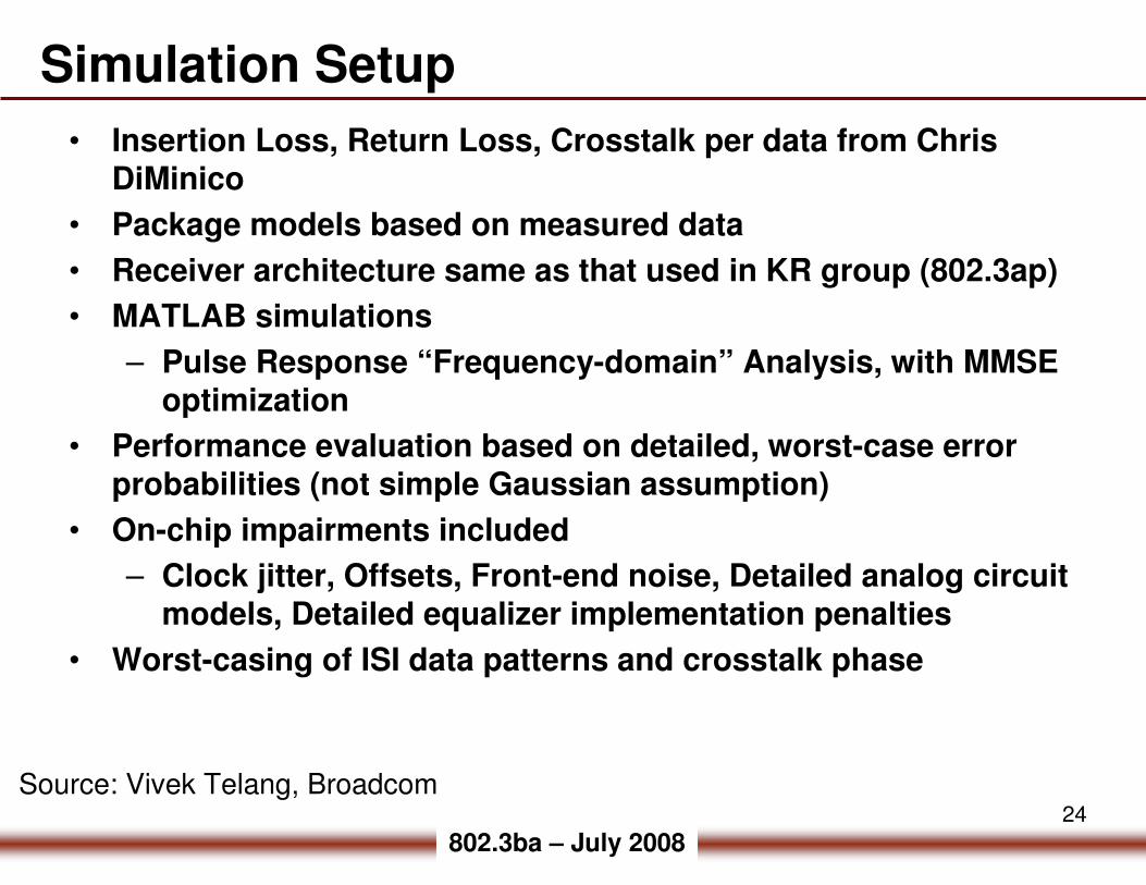
Simulation Setup
• Insertion Loss, Return Loss, Crosstalk per data from Chris DiMinico
• Package models based on measured data
• Receiver architecture same as that used in KR group (802.3ap)
• MATLAB simulations
– Pulse Response “Frequency-domain” Analysis, with MMSE optimization
• Performance evaluation based on detailed, worst-case error probabilities (not simple Gaussian assumption)
• On-chip impairments included
– Clock jitter, Offsets, Front-end noise, Detailed analog circuit models, Detailed equalizer implementation penalties
• Worst-casing of ISI data patterns and crosstalk phase
Source: Vivek Telang, Broadcom

25
802.3ba – July 2008
Channel models
Source: Vivek Telang, Broadcom

26
802.3ba – July 2008
18.5
SNR (dB)
Slicer SNR & BER
1.4x10⁻¹⁷
BER
Simulation results
Source: Vivek Telang, Broadcom

27
802.3ba – July 2008
39. Physical Medium Dependent (PMD) sublayer and baseband medium,type 1000BASE-CX (short-haul copper)
Connectors meeting the requirements of 39.5.1.1 (Style-1) and 39.5.1.2 (Style-2) shall be used as the mechanical interface between the PMD of 39.3 and the jumper cable assembly of 39.4. The plug connector shall be used on the jumper cable assembly and the receptacle on the PHY. Style-1 or style-2 connectors may be used as the MDI interface. To limit possible cross-plugging with non-1000BASE-CX interfaces that make use of the Style-1 connector, it is recommended that the Style-2 connector be used as the MDI connector.
39.8.3 Major capabilities/options
39.8.4 PICS proforma tables for Physical Medium Dependent (PMD) sublayer and basebandmedium, type 1000BASE-CX (short-haul copper)
39.8.4.1 PMD functional specifications
*STY1 Style-1 MDI 39.5 Either the style-1 or the style-2
MDI must be provided O/1 Yes [ ] No [ ]*STY2 Style-2 MDI 39.5 O/1 Yes [ ] No [ ]
1000BASE-CX (short-haul copper) – MDI


![CR10 · 2019-04-01 · CR10 6 720 647 292-00.2O EMS plus [de] Installations- und Bedienungsanleitung 2 [es] Instrucciones de instalación y de uso 14 [fl] Installatie- en bedieningshandleiding](https://static.fdocuments.net/doc/165x107/5f3fd8cbc907de0f6a656ff9/cr10-2019-04-01-cr10-6-720-647-292-002o-ems-plus-de-installations-und-bedienungsanleitung.jpg)


![Draft Amendment 1 to Recommendation ITU-T G.798 (2010 ... · [IEEE 802.3ba] IEEE Std. 802.3ba-2010, Information Technology – Local and Metropolitan Area Networks –Part 3: Carrier](https://static.fdocuments.net/doc/165x107/612920ec11f9fa1eca5f62b2/draft-amendment-1-to-recommendation-itu-t-g798-2010-ieee-8023ba-ieee-std.jpg)