
802.11ac Wave 2 technology deep dive and deployment recommendations
68
#ATM15 | 802.11ac Wave 2 Technology Deep Dive and Deployment Recommendations Eric Johnson and Peter Lane March 2015 @ArubaNetworks
-
Upload
aruba-networks-an-hp-company -
Category
Technology
-
view
2.074 -
download
4
Transcript of 802.11ac Wave 2 technology deep dive and deployment recommendations

#ATM15 |
802.11ac Wave 2 Technology Deep Dive and
Deployment Recommendations
Eric Johnson and Peter LaneMarch 2015
@ArubaNetworks

2 CONFIDENTIAL © Copyright 2015. Aruba Networks, Inc. All rights reserved#ATM15 |
• 11ac Standards Physical Layer Overview
• 11ac Data Rates
• Antennas
• 11ac Beamforming
• Field Results
Agenda

33#ATM15 |
What is Wave 2?

4 CONFIDENTIAL © Copyright 2015. Aruba Networks, Inc. All rights reserved#ATM15 |
802.11ac Technology Overview
Think of 11ac as an extension of 11n
• 11n specification introduced/leveraged:• 2.4 and 5 GHz supported• Wider channels (40 MHz)• Better modulation (64-QAM)• Additional streams (up to 4
streams)• Beam forming (explicit and
implicit)• Backwards compatibility with
11a/b/g
11ac Wave 1 introduced:• Even wider channels (80 MHz)
• Better modulation (256-QAM)
• Additional streams (up to 8)
• Beam forming (explicit)
• Backwards compatibility with 11a/b/g/n
• Refer to http://www.802-11.ac.net for in-depth information

5 CONFIDENTIAL © Copyright 2015. Aruba Networks, Inc. All rights reserved#ATM15 |
Wave 2 of 11ac
• What will wave 2 802.11ac offer?• MU-MIMO
• Use AP MIMO resources more effectively• Transmit data to multiple devices simultaneously: for example 4SS AP streaming
data to four 1SS clients simultaneously
• 4x4:4SS• Benefit of additional stream mostly for MU-MIMO• Not anticipating any 4x4:4SS client devices• Adds 33% to max data rate in SU-MIMO
• VHT160• Doubles max datarate• Practical problem: only 2 VHT160 channels available in entire 5GHz band
• Max 5GHz radio data rates increases again!• 450 (11n 3x3 HT40), 1,300 (11ac 3x3 VHT80), 3,467 (11ac 4x4 VHT160)
• When will it be available?• Products mid to late 2015• WFA certification scheduled for 2016

66#ATM15 |
Channel Allocations

7 CONFIDENTIAL © Copyright 2015. Aruba Networks, Inc. All rights reserved#ATM15 |
Current 5GHz FCC Channel plan
23dBm 30dBm 30dBm 36dBm

8 CONFIDENTIAL © Copyright 2015. Aruba Networks, Inc. All rights reserved#ATM15 |
Potential Future 5GHz FCC Channel plan
23dBm 30dBm 30dBm 36dBmTBD 30dBm

9 CONFIDENTIAL © Copyright 2015. Aruba Networks, Inc. All rights reserved#ATM15 |
Current 5GHz ETSI Channel plan
23dBm 30dBm 30dBm

1010#ATM15 |
Understanding 11ac Data Rates (Wave 1 and Wave 2)

11 CONFIDENTIAL © Copyright 2015. Aruba Networks, Inc. All rights reserved#ATM15 |
Sub-carriers
52 subcarriers (48 usable) for a 20 MHz non-HT
mode (legacy 802.11a/g) channel
fc +10MHz-10MHz
26 carriers 26 carriers
56 subcarriers (52 usable) for a 20 MHz HT
mode (802.11n) channel
fc
28 carriers 28 carriers
114 subcarriers (108 usable) for a 40 MHz HT mode (802.11n) channelfc +10MHz-20MHz
57 carriers 57 carriers
+20MHz-10MHz
242 subcarriers (234 usable) for a 80 MHz VHT mode (802.11ac) channel
An 80+80MHz or 16MHz channel is exactly two 80MHz channels, for 484 subcarriers (468 usable)
121 carriers 121 carriers
fc +10MHz-20MHz +20MHz-10MHz-40MHz -30MHz +30MHz +40MHz
OFDM subcarriers used in 802.11a, 802.11n and 802.11ac
+10MHz-10MHz
Guard Tones

12 CONFIDENTIAL © Copyright 2015. Aruba Networks, Inc. All rights reserved#ATM15 |
Terminology
Symbol: basic element containing 1 to 8 bits of information
Tone/Sub-Carriers: OFDM is made up of many tones. Each symbol is mapped to a tone.
Cyclic Extension: technique used in OFDM to protect against multipath interference
– You need cyclic extension but it is dead air and consumes transmit time
Guard Band: Space between channels. In these regions tones have a constant value of zero amplitude
Pilot Tones: Used to train the receiver and estimate the channel
Radio Channel: For Wi-Fi 20, 40, 80, or 160 MHz of spectrum
Propagation Channel: everything that happens between the transmitter and receiver
FEC: Forward Error Correction. Redundant information that is sent to assist the receiver in decoding the bits.

13 CONFIDENTIAL © Copyright 2015. Aruba Networks, Inc. All rights reserved#ATM15 |
QAM constellations
Amplitude +1
Amplitude -1
Quadra
ture
-1
Quadra
ture
+1
Amplitude +1
Amplitude -1
Quadra
ture
-1
Quadra
ture
+1
Amplitude +1
Amplitude -1
Quadra
ture
-1
Quadra
ture
+1
16-QAM constellation 64-QAM constellation 256-QAM constellation
Constellation diagrams for 16-, 64-, 256-QAM
14 CONFIDENTIAL © Copyright 2015. Aruba Networks, Inc. All rights reserved#ATM15 |
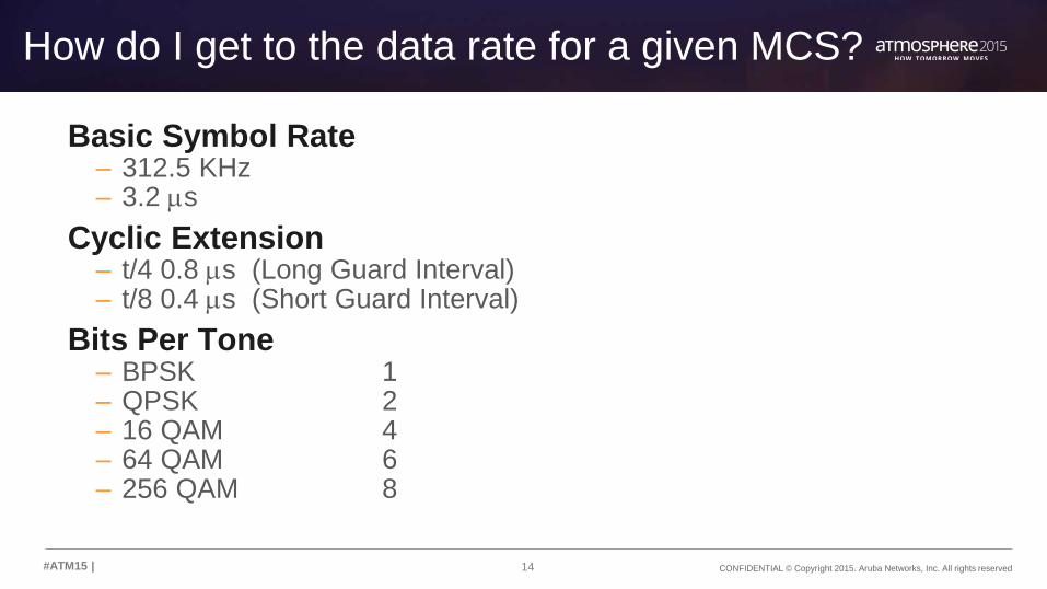
How do I get to the data rate for a given MCS?
Basic Symbol Rate– 312.5 KHz– 3.2 ms
Cyclic Extension– t/4 0.8 ms (Long Guard Interval)– t/8 0.4 ms (Short Guard Interval)
Bits Per Tone– BPSK 1– QPSK 2– 16 QAM 4– 64 QAM 6– 256 QAM 8

15 CONFIDENTIAL © Copyright 2015. Aruba Networks, Inc. All rights reserved#ATM15 |
20 MHz
BPSK 16.25 Mbps
QPSK 32.5 Mbps
16 QAM 65 Mbps
64 QAM 97.5 Mbps
256 QAM 130 Mbps
Raw Data Rates
#Tones * Bits per Tone * Symbol Rate
– 16 QAM, 20 MHz
– 52 * 4 * 0.3125 = 65 Mbps40 MHz
BPSK 33.75 Mbps
QPSK 67.5 Mbps
16 QAM 135 Mbps
64 QAM 202.5 Mbps
256 QAM 270 Mbps
80 MHz
BPSK 73.125 Mbps
QPSK 146.25 Mbps
16 QAM 292.5 Mbps
64 QAM 438.75 Mbps
256 QAM 585 Mbps
160 MHz
BPSK 146.25 Mbps
QPSK 292.5 Mbps
16 QAM 585 Mbps
64 QAM 877.5 Mbps
256 QAM 1170 Mbps

16 CONFIDENTIAL © Copyright 2015. Aruba Networks, Inc. All rights reserved#ATM15 |
Correct for Cyclic Extension20 MHz t/4
BPSK 13 Mbps
QPSK 26 Mbps
16 QAM 52 Mbps
64 QAM 78 Mbps
256 QAM 104 Mbps
20 MHz t/8
BPSK 14.4 Mbps
QPSK 28.9 Mbps
16 QAM 57.8 Mbps
64 QAM 86.7 Mbps
256 QAM 115.6 Mbps
40 MHz t/4
BPSK 27 Mbps
QPSK 54 Mbps
16 QAM 108 Mbps
64 QAM 162 Mbps
256 QAM 216 Mbps
40 MHz t/8
BPSK 30 Mbps
QPSK 60 Mbps
16 QAM 120 Mbps
64 QAM 180 Mbps
256 QAM 240 Mbps
80 MHz t/4
BPSK 58.5 Mbps
QPSK 117 Mbps
16 QAM 234 Mbps
64 QAM 351 Mbps
256 QAM 468 Mbps
80 MHz t/8
BPSK 65 Mbps
QPSK 130 Mbps
16 QAM 260 Mbps
64 QAM 390 Mbps
256 QAM 520 Mbps
160 MHz t/4
BPSK 117 Mbps
QPSK 234 Mbps
16 QAM 468 Mbps
64 QAM 702 Mbps
256 QAM 936 Mbps
160 MHz t/8
BPSK 130 Mbps
QPSK 260 Mbps
16 QAM 520 Mbps
64 QAM 780 Mbps
256 QAM 1040 Mbps

17 CONFIDENTIAL © Copyright 2015. Aruba Networks, Inc. All rights reserved#ATM15 |
Apply FEC Coding
17
MCS Index Modulation Coding 20 MHz 40 MHz 80 MHz 160 MHz
0 BPSK 1/2 6.5 13.5 29.3 58.5
1 QPSK 1/2 13.0 27.0 58.5 117.0
2 QPSK 3/4 19.5 40.5 87.8 175.5
3 16 QAM 1/2 26.0 54.0 117.0 234.0
4 16 QAM 3/4 39.0 81.0 175.5 351.0
5 64 QAM 2/3 52.0 108.0 234.0 468.0
6 64 QAM 3/4 58.5 121.5 263.3 526.5
7 64 QAM 5/6 65.0 135.0 292.5 585.0
8 256 QAM 3/4 78.0 162.0 351.0 702.0
9 256 QAM 5/6 86.7 180.0 390.0 780.0
MCS Index Modulation Coding 20 MHz 40 MHz 80 MHz 160 MHz
0 BPSK 1/2 7.2 15.0 32.5 65.0
1 QPSK 1/2 14.4 30.0 65.0 130.0
2 QPSK 3/4 21.7 45.0 97.5 195.0
3 16 QAM 1/2 28.9 60.0 130.0 260.0
4 16 QAM 3/4 43.3 90.0 195.0 390.0
5 64 QAM 2/3 57.8 120.0 260.0 520.0
6 64 QAM 3/4 65.0 135.0 292.5 585.0
7 64 QAM 5/6 72.2 150.0 325.0 650.0
8 256 QAM 3/4 86.7 180.0 390.0 780.0
9 256 QAM 5/6 96.3 200.0 433.3 866.7
t/4
t/8 SGI
Net Bit Rate per Stream
Net Bit Rate

18CONFIDENTIAL
© Copyright 2014. Aruba Networks, Inc.
All rights reserved#AirheadsConf
Practical Coverage

19CONFIDENTIAL
© Copyright 2014. Aruba Networks, Inc.
All rights reserved#AirheadsConf
Coverage Example
1. Sample coverage for 3x3:3 11n AP (or 3x3:3 11ac AP
with 11n clients) in HT40 mode
•Coverage area sustains MCS5 and up
360405450

20 CONFIDENTIAL © Copyright 2015. Aruba Networks, Inc. All rights reserved#ATM15 |
Coverage Example
2. Upgrade to 3x3:3 11ac AP with 11ac clients, still using 40Mhz channels (VHT40)
Radius for 600Mbps (MCS9) area is 1/4 of that for 450Mbps (MCS7)
360405450
540
600
21 CONFIDENTIAL © Copyright 2015. Aruba Networks, Inc. All rights reserved#ATM15 |
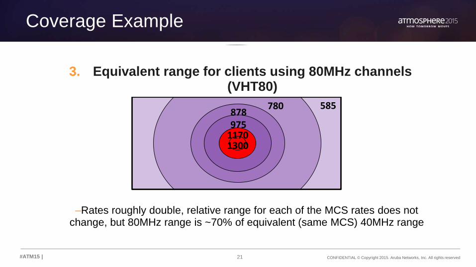
Coverage Example
3. Equivalent range for clients using 80MHz channels (VHT80)
–Rates roughly double, relative range for each of the MCS rates does not change, but 80MHz range is ~70% of equivalent (same MCS) 40MHz range
780878975
11701300
585

22 CONFIDENTIAL © Copyright 2015. Aruba Networks, Inc. All rights reserved#ATM15 |
Relative Range 802.11ac Rates
Datarate40MHz 80MHz
MCS0 45 97.5MCS1 90 195MCS2 135 292.5MCS3 180 390MCS4 270 585MCS5 360 780MCS6 405 877.5MCS7 450 975MCS8 540 1,170MCS9 600 1,300
Signal level and relative range-dB r %
MCS0 87 63MCS1 85 50MCS2 83 40MCS3 79 25MCS4 76 18MCS5 71 10MCS6 66 5.6MCS7 63 4.0MCS8 58 2.2MCS9 51 1.0

23 CONFIDENTIAL © Copyright 2015. Aruba Networks, Inc. All rights reserved#ATM15 |
What about Wave 2 coverage?
• 160 MHz is just two 80 MHz sandwiched together
• No increase in noise floor
• No new modulations are introduced
• No new circles in the bullseye
• Additional streams do not change coverage area

2424#ATM15 |
BASIC BEAMFORMING

25 CONFIDENTIAL © Copyright 2015. Aruba Networks, Inc. All rights reserved#ATM15 |
Antenna Basic Physics
• When the charges oscillate the waves go up and down with the charges and radiate away
• With a single element the energy leaves uniformly.
• Also known as omni-directionally

26 CONFIDENTIAL © Copyright 2015. Aruba Networks, Inc. All rights reserved#ATM15 |
Building Arrays: 2 Elements
• By introducing additional antenna elements we can control the way that the energy radiates
• 2 elements excited in phase
l/2
0
15
30
45
60
7590
105
120
135
150
165
180
195
210
225
240
255270
285
300
315
330
345
dB Plot

27 CONFIDENTIAL © Copyright 2015. Aruba Networks, Inc. All rights reserved#ATM15 |
0
15
30
45
60
7590
105
120
135
150
165
180
195
210
225
240
255270
285
300
315
330
345
Building Arrays: 4 Elements
• By introducing additional antenna elements we can control the way that the energy radiates
• 4 elements excited in phase
– Equal amplitude
dB Plot

28 CONFIDENTIAL © Copyright 2015. Aruba Networks, Inc. All rights reserved#ATM15 |
0
15
30
45
60
7590
105
120
135
150
165
180
195
210
225
240
255270
285
300
315
330
345
Building Arrays: 4 Elements
• By shaping the amplitude we can control sidelobes
• 4 elements excited in phase
– Amplitude 1, 3, 3, 1
dB Plot

29 CONFIDENTIAL © Copyright 2015. Aruba Networks, Inc. All rights reserved#ATM15 |
0
15
30
45
60
7590
105
120
135
150
165
180
195
210
225
240
255270
285
300
315
330
345
Building Arrays: 4 Elements Phase
• By altering phase we can alter the direction that the energy travels
• 4 elements excited with phase slope
– Equal amplitude
dB Plot

3030#ATM15 |
Orthogonal Patterns

31 CONFIDENTIAL © Copyright 2015. Aruba Networks, Inc. All rights reserved#ATM15 |
2 Elements
0
10
20
30
40
50
60
708090100
110
120
130
140
150
160
170
180
190
200
210
220
230
240
250260 270 280
290
300
310
320
330
340
350
a
a 3 dB per division
0
10
20
30
40
50
60
708090100
110
120
130
140
150
160
170
180
190
200
210
220
230
240
250260 270 280
290
300
310
320
330
340
350
a
a 3 dB per division

32 CONFIDENTIAL © Copyright 2015. Aruba Networks, Inc. All rights reserved#ATM15 |
3 Elements
0
10
20
30
40
50
60
708090100
110
120
130
140
150
160
170
180
190
200
210
220
230
240
250260 270 280
290
300
310
320
330
340
350
a
a 3 dB per division
0
10
20
30
40
50
60
708090100
110
120
130
140
150
160
170
180
190
200
210
220
230
240
250260 270 280
290
300
310
320
330
340
350
a
a 3 dB per division
0
10
20
30
40
50
60
708090100
110
120
130
140
150
160
170
180
190
200
210
220
230
240
250260 270 280
290
300
310
320
330
340
350
a
a 3 dB per division

33 CONFIDENTIAL © Copyright 2015. Aruba Networks, Inc. All rights reserved#ATM15 |
4 Elements
0
10
20
30
40
50
60
708090100
110
120
130
140
150
160
170
180
190
200
210
220
230
240
250260 270 280
290
300
310
320
330
340
350
a
a 3 dB per division
0
10
20
30
40
50
60
708090100
110
120
130
140
150
160
170
180
190
200
210
220
230
240
250260 270 280
290
300
310
320
330
340
350
a
a 3 dB per division
0
10
20
30
40
50
60
708090100
110
120
130
140
150
160
170
180
190
200
210
220
230
240
250260 270 280
290
300
310
320
330
340
350
a
a 3 dB per division
0
10
20
30
40
50
60
708090100
110
120
130
140
150
160
170
180
190
200
210
220
230
240
250260 270 280
290
300
310
320
330
340
350
a
a 3 dB per division

34 CONFIDENTIAL © Copyright 2015. Aruba Networks, Inc. All rights reserved#ATM15 |
8 Elements
0
10
20
30
40
50
60
708090100
110
120
130
140
150
160
170
180
190
200
210
220
230
240
250260 270 280
290
300
310
320
330
340
350
a
a 3 dB per division
0
10
20
30
40
50
60
708090100
110
120
130
140
150
160
170
180
190
200
210
220
230
240
250260 270 280
290
300
310
320
330
340
350
a
a 3 dB per division
0
10
20
30
40
50
60
708090100
110
120
130
140
150
160
170
180
190
200
210
220
230
240
250260 270 280
290
300
310
320
330
340
350
a
a 3 dB per division
0
10
20
30
40
50
60
708090100
110
120
130
140
150
160
170
180
190
200
210
220
230
240
250260 270 280
290
300
310
320
330
340
350
a
a 3 dB per division
0
10
20
30
40
50
60
708090100
110
120
130
140
150
160
170
180
190
200
210
220
230
240
250260 270 280
290
300
310
320
330
340
350
a
a 3 dB per division

35 CONFIDENTIAL © Copyright 2015. Aruba Networks, Inc. All rights reserved#ATM15 |
Triangular 3 element
0
10
20
30
40
50
60
708090100
110
120
130
140
150
160
170
180
190
200
210
220
230
240
250260 270 280
290
300
310
320
330
340
350
a
a 3 dB per division
0
10
20
30
40
50
60
708090100
110
120
130
140
150
160
170
180
190
200
210
220
230
240
250260 270 280
290
300
310
320
330
340
350
a
a 3 dB per division

3636#ATM15 |
802.11ac Beamforming

37 CONFIDENTIAL © Copyright 2015. Aruba Networks, Inc. All rights reserved#ATM15 |
11ac Beamforming: Notes
Works with clients that support 11ac beamforming function– This is at a minimum all 11ac client devices using Broadcom chipsets– Support will have to come to all devices to compete with Broadcom offering
11ac beamforming is standards based– first standard that is doing this the “right” way– 11ac beamforming represents the consensus view of the 1000’s of contributors to
the standards process
11ac beamforming is implemented in baseband. – It works with all antenna subsystems– The total number of beamforming combinations is effectively infinite
11ac actively tracks users so has a recent channel estimate between the AP and client that is updated frequently

38 CONFIDENTIAL © Copyright 2015. Aruba Networks, Inc. All rights reserved#ATM15 |
Background
11n/11ac MIMO
• 1 Stream
• All antenna elements send same data with time delay
• 3 Streams
• 1 Stream is sent on each antenna
11ac Beamforming
• 1 Stream
• Stream is spatially multiplexed across the three antennas
• Same info but phase and amplitude differences
• 3 Streams
• All three streams are spatially multiplexed across the
three antennas
39 CONFIDENTIAL © Copyright 2015. Aruba Networks, Inc. All rights reserved#ATM15 |
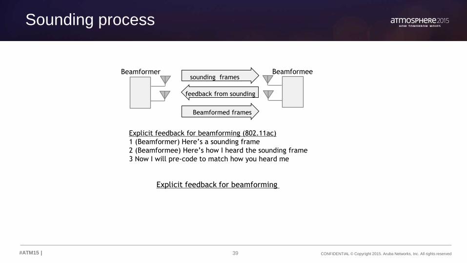
Sounding process
Explicit feedback for beamforming (802.11ac)
1 (Beamformer) Here’s a sounding frame
2 (Beamformee) Here’s how I heard the sounding frame
3 Now I will pre-code to match how you heard me
sounding frames
Beamformed frames
feedback from sounding
Explicit feedback for beamforming
Beamformer Beamformee

40 CONFIDENTIAL © Copyright 2015. Aruba Networks, Inc. All rights reserved#ATM15 |
The Basic Model: Regular MIMO
y=Hx– H is the propagation channel
– y is what comes out of each antenna at the receiving end
– With 3 tx and 3 rx antennas H is a 3x3 matrix, y and x are single vectors
– If you can determine the inverse matrix of H you can calculate
• Client receiver estimates this from preamble and pilot tones
– H-1y=H-1Hx
• H-1y=x
x1
x2
x3
y1
y2
y3
h11
h21
h31
h13

41 CONFIDENTIAL © Copyright 2015. Aruba Networks, Inc. All rights reserved#ATM15 |
The MATRIX
5- 4- 3- 2- 1- 0 1 2 3 4 51 10
4-
1 103-
0.01Antenna 1
Antenna 2
Antenna 3
Wavelengths
E Fi
eld
Am
plitu
de
Client Antennas
h11h21
h31
AP Client

42 CONFIDENTIAL © Copyright 2015. Aruba Networks, Inc. All rights reserved#ATM15 |
Beamforming
• If the client can send back the channel estimate to the AP then beamforming can be executed
• The signal from each antenna then is a combination of the three stream
Non Beamformed
Streams
Beamformed
Streams

4343#ATM15 |
Practical Examples: Beamforming

44 CONFIDENTIAL © Copyright 2015. Aruba Networks, Inc. All rights reserved#ATM15 |
Dual Polarization
• At the source end – one signal is vertically polarized – other is horizontally polarized
• At the receiver the antenna is oriented the same way.– With a line of sight link the V signal ends up on the V port– The H signal shows up on the H port
• In propagation terms this is simply
• What if the receiver is rotated by 45 degrees. The H and V pol divide onto to the two rotated port on the receiver

45 CONFIDENTIAL © Copyright 2015. Aruba Networks, Inc. All rights reserved#ATM15 |
MIMO in Action: Polarization
transmitter
Receiver HR
VT=VR+HR + = HT=HR-VR - =
VT
HT
receiver
VR HR VR HR
VR

46 CONFIDENTIAL © Copyright 2015. Aruba Networks, Inc. All rights reserved#ATM15 |
Line of Sight
• 3 stream AP
• Smartphone– 1 Antenna/1 Stream
Client
AP
0
10
20
30
40
50
6070
8090100110
120
130
140
150
160
170
180
190
200
210
220
230
240250
260 270 280290
300
310
320
330
340
350

47 CONFIDENTIAL © Copyright 2015. Aruba Networks, Inc. All rights reserved#ATM15 |
Simple Reflection
• Let’s introduce two reflection surfaces and look at the impact of one bounce on each side
Client
AP
0
10
20
30
40
50
6070
8090100110
120
130
140
150
160
170
180
190
200
210
220
230
240250
260 270 280290
300
310
320
330
340
350
AP
Antenna Pattern
S1
0
10
20
30
40
50
6070
8090100110
120
130
140
150
160
170
180
190
200
210
220
230
240250
260 270 280290
300
310
320
330
340
350

48 CONFIDENTIAL © Copyright 2015. Aruba Networks, Inc. All rights reserved#ATM15 |
Multi Stream Client
• The reflections allow beamforming to send different streams with different antenna patterns through the system
Client
AP
0
10
20
30
40
50
6070
8090100110
120
130
140
150
160
170
180
190
200
210
220
230
240250
260 270 280290
300
310
320
330
340
350
0
10
20
30
40
50
6070
8090100110
120
130
140
150
160
170
180
190
200
210
220
230
240250
260 270 280290
300
310
320
330
340
350
0
10
20
30
40
50
6070
8090100110
120
130
140
150
160
170
180
190
200
210
220
230
240250
260 270 280290
300
310
320
330
340
350
Str
ea
m 1
Str
eam
2S
tre
am
3

49 CONFIDENTIAL © Copyright 2015. Aruba Networks, Inc. All rights reserved#ATM15 |
Beamforming
Stream 3 now appears on all three antenna– Here is how each transmitted component shows up at the client
5- 4- 3- 2- 1- 0 1 2 3 4 51 10
3-
0.01
0.1
1
10Antenna 1
Wavelengths
E Fi
eld
Am
plitu
de
Now add them!

50 CONFIDENTIAL © Copyright 2015. Aruba Networks, Inc. All rights reserved#ATM15 |
Similarly Stream 1 and 2
Stream 1
Stream 2

Sub-carriers
52 subcarriers (48 usable) for a 20 MHz non-HT
mode (legacy 802.11a/g) channel
fc +10MHz-10MHz
26 carriers 26 carriers
56 subcarriers (52 usable) for a 20 MHz HT
mode (802.11n) channel
fc
28 carriers 28 carriers
114 subcarriers (108 usable) for a 40 MHz HT mode (802.11n) channelfc +10MHz-20MHz
57 carriers 57 carriers
+20MHz-10MHz
242 subcarriers (234 usable) for a 80 MHz VHT mode (802.11ac) channel
An 80+80MHz or 16MHz channel is exactly two 80MHz channels, for 484 subcarriers (468 usable)
121 carriers 121 carriers
fc +10MHz-20MHz +20MHz-10MHz-40MHz -30MHz +30MHz +40MHz
OFDM subcarriers used in 802.11a, 802.11n and 802.11ac
+10MHz-10MHz
Guard Tones

0
10
20
30
40
50
6070
8090100110
120
130
140
150
160
170
180
190
200
210
220
230
240250
260 270 280290
300
310
320
330
340
350
0
10
20
30
40
50
6070
8090100110
120
130
140
150
160
170
180
190
200
210
220
230
240250
260 270 280290
300
310
320
330
340
350
0
10
20
30
40
50
6070
8090100110
120
130
140
150
160
170
180
190
200
210
220
230
240250
260 270 280290
300
310
320
330
340
350
The standards based algorithm actually works out patterns for each sub carrier
Below is the pattern for stream 1 at 5460, 5500, 5540 MHz
11ac Beamforming across an 80 MHz channel

5353#ATM15 |
802.11ac MU-MIMO

54 CONFIDENTIAL © Copyright 2015. Aruba Networks, Inc. All rights reserved#ATM15 |
The Basic Model: MU-MIMO
y=Hx– H is the propagation channel
– y is what comes out of each antenna at each of the clients
– The channel matrix is built from sounding each client
x1
x2
x3
y1
y2
y3
h11
h21
h31
h13
With MU-MIMO each client sends a piece of the matrix

55 CONFIDENTIAL © Copyright 2015. Aruba Networks, Inc. All rights reserved#ATM15 |
3 Clients: 4x4 AP
Room Width: 10m
Room Length: 10m
Room Height: 7m
AP Antenna Pattern

56 CONFIDENTIAL © Copyright 2015. Aruba Networks, Inc. All rights reserved#ATM15 |
20- 19- 18- 17- 16- 15- 14- 13- 12- 11- 10- 9- 8- 7- 6- 5- 4- 3- 2- 1- 0 1 2 3 4 5 6 7 8 9 10 11 12 13 14 15 16 17 18 19 200.01
0.1
1
10
Wavelengths
E Fi
eld
Am
plitu
de
Stream 1 to Client 1
Stream 1 Antenna Pattern

57 CONFIDENTIAL © Copyright 2015. Aruba Networks, Inc. All rights reserved#ATM15 |
Stream 2 to Client 2
Stream 2 Antenna Pattern
20- 19- 18- 17- 16- 15- 14- 13- 12- 11- 10- 9- 8- 7- 6- 5- 4- 3- 2- 1- 0 1 2 3 4 5 6 7 8 9 10 11 12 13 14 15 16 17 18 19 200.01
0.1
1
10
Wavelengths
E Fi
eld
Am
plitu
de

58 CONFIDENTIAL © Copyright 2015. Aruba Networks, Inc. All rights reserved#ATM15 |
Stream 3 to Client 3
20- 19- 18- 17- 16- 15- 14- 13- 12- 11- 10- 9- 8- 7- 6- 5- 4- 3- 2- 1- 0 1 2 3 4 5 6 7 8 9 10 11 12 13 14 15 16 17 18 19 200.01
0.1
1
10
Wavelengths
E Fi
eld
Am
plitu
de
Stream 3 Antenna Pattern

5959#ATM15 |
Practical Applications of Wave 2

60 CONFIDENTIAL © Copyright 2015. Aruba Networks, Inc. All rights reserved#ATM15 |
Wave 2 Data Rates
1 SSS 2 SS 3 SS 4 SS
3 SS VHT 80 MHz 433 867 1300 N/A
4 SS VHT 80 MHz 433 867 1300 1733
3 SS VHT 160 MHz 867 1733 2600 N/A
4 SS VHT 160 MHz 867 1733 2600 3466

61 CONFIDENTIAL © Copyright 2015. Aruba Networks, Inc. All rights reserved#ATM15 |
TCP Throughputs
1 SS 2 SS 3 SS 4 SS
3 SS VHT 80 AP 303 607 910 N/A
4 SS VHT 80 AP 303 607 910 1213
3 SS VHT 160 AP 607 1213 1820 N/A
4 SS VHT 160 AP 607 1213 1820 2426
• 70% of data rate is best case throughput for wireless TCP traffic.
• Throughput is lost to:
• TCP traffic
• Management traffic
• Assuming best SNR and single client

62 CONFIDENTIAL © Copyright 2015. Aruba Networks, Inc. All rights reserved#ATM15 |
MU-MIMO Best Case Throughputs
MU-MIMO
1 SS
clients
2 SS
clients
3 SS VHT 80
AP 683 622
4 SS VHT 80
AP 910 789
• ~75% efficiency for 1 SS clients
• ~65% efficiency for 2 SS clients
• Efficiency goes down from there.
• 3 SS + 1 SS is less efficient than
separately serving to 3 SS and 1 SS
• MU-MIMO has client side dependancies
MU-MIMO
max 1 SS
clients
Max 2
SS
clients
3 SS VHT
160 AP 1365 1244
4 SS VHT
160 AP 1820 1578

63 CONFIDENTIAL © Copyright 2015. Aruba Networks, Inc. All rights reserved#ATM15 |
What does that mean for 11ac wave 2?
MU-MIMO efficiency means we see pretty much the same max real-world
throughputs as wave 1
MU-MIMO allows the network to reach max throughput much more often
FCC opening up spectrum is critical to realize the potential of 160 MHz channels
Real world throughputs will be brought down from best case by:
• Client capability mix (11n and non-MU-MIMO devices)
• Client location distribution (weak SNR)
• Client count (air contention increases with number of clients)

64 CONFIDENTIAL © Copyright 2015. Aruba Networks, Inc. All rights reserved#ATM15 |
Do I need 2.5 gbps for wireless?
Short answer: No.
Long Answer:
• > 1gbps will be needed at some point, but we aren’t there yet.
• No IEEE standard for 2.5 gbps
• Limited investment protection
• Potential wired and wireless interop issues
• Real world throughputs with 80 MHz channels will not require >1 gbps
• Wired traffic is full duplex, wireless is half
• 2.5 gbps carries a large price premium today

65 CONFIDENTIAL © Copyright 2015. Aruba Networks, Inc. All rights reserved#ATM15 |
AMSDU/AMPDU

66 CONFIDENTIAL © Copyright 2015. Aruba Networks, Inc. All rights reserved#ATM15 |
Deployment recommendations
VRDs are the place to start
• RF and Roaming Optimization for 11ac
67 CONFIDENTIAL © Copyright 2015. Aruba Networks, Inc. All rights reserved#ATM15 |
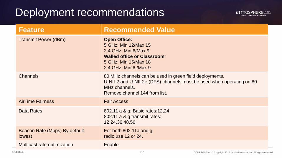
Deployment recommendations
Feature Recommended Value
Transmit Power (dBm) Open Office:
5 GHz: Min 12/Max 15
2.4 GHz: Min 6/Max 9
Walled office or Classroom:
5 GHz: Min 15/Max 18
2.4 GHz: Min 6 /Max 9
Channels 80 MHz channels can be used in green field deployments.
U-NII-2 and U-NII-2e (DFS) channels must be used when operating on 80
MHz channels.
Remove channel 144 from list.
AirTime Fairness Fair Access
Data Rates 802.11 a & g: Basic rates:12,24
802.11 a & g transmit rates:
12,24,36,48,56
Beacon Rate (Mbps) By default
lowest
For both 802.11a and g
radio use 12 or 24.
Multicast rate optimization Enable

THANK YOU
68#ATM15 | @ArubaNetworks