
801 BOARDMAN RD PROJECT MANUAL - County of...
169
SOULE PARK RESTROOM RENOVATIONS BUILDINGS 2902 & 2903 COUNTY OF VENTURA – PARKS DEPARTMENT 801 BOARDMAN RD OJAI, CALIFORNIA 93023 PROJECT MANUAL 12 December 2014 KBZ JOB NO. 14025 Owner: COUNTY OF VENTURA - PARKS DEPARTMENT 11201 Riverbank Drive, Suite A1 Ventura, CA 93004 Phone (805) 654-3968 Architect: KRUGER BENSEN ZIEMER ARCHITECTS, INC. 199 Figueroa St Suite 100A Ventura, CA 93001 Phone (805) 650-1033 www.kbzarch.com
Transcript of 801 BOARDMAN RD PROJECT MANUAL - County of...

SOULE PARK RESTROOM RENOVATIONS BUILDINGS 2902 & 2903
COUNTY OF VENTURA – PARKS DEPARTMENT 801 BOARDMAN RD OJAI, CALIFORNIA 93023
PROJECT MANUAL 12 December 2014 KBZ JOB NO. 14025
Owner: COUNTY OF VENTURA - PARKS DEPARTMENT 11201 Riverbank Drive, Suite A1 Ventura, CA 93004 Phone (805) 654-3968
Architect: KRUGER BENSEN ZIEMER ARCHITECTS, INC.
199 Figueroa St Suite 100A Ventura, CA 93001 Phone (805) 650-1033 www.kbzarch.com

THIS PAGE INTENTIONALLY LEFT BLANK

SIGNATURE PAGE 12 DECEMBER 2014
SPECIFICATION MANUAL Soule Park Restroom Renovations Buildings 2902 & 2903 County of Ventura – Parks Department
KRUGER BENSEN ZIEMER ARCHITECTS, INC. 199 Figueroa St, Suite 100A, Ventura, CA 93001
Todd A Jespersen C-25839 Principal Architect License No. Stamp
MECHANICAL ENGINEER AE GROUP 838 E Front St, Ventura, CA 93001
Phil White M-15777 Project Engineer License No. Stamp
COUNTY OF VENTURA – PARKS DEPARTMENT SOULE PARK RESTROOM RENOVATIONS

SIGNATURE PAGE 12 DECEMBER 2014
THIS PAGE INTENTIONALLY LEFT BLANK
COUNTY OF VENTURA – PARKS DEPARTMENT SOULE PARK RESTROOM RENOVATIONS

DIRECTORY 12 DECEMBER 2014
PROJECT MANUAL
SOULE PARK RESTROOM RENOVATIONS BUILDINGS 2902 & 2903
801 Boardman Rd Ojai, CA 93023
OWNER: COUNTY OF VENTURA Parks Department Theresa Lubin, Parks Manager 11201 Riverbank Drive, Suite A1 Ventura, CA 93004 (805) 654-3968
ARCHITECT: KRUGER BENSEN ZIEMER ARCHITECTS, INC.
199 Figueroa St, Suite 100A Ventura, CA 93001 (805) 650-1033
MECHANICAL ENGINEER: AE GROUP
838 E Front St Ventura, CA 93001 (805) 653-1722
COUNTY OF VENTURA – PARKS DEPARTMENT SOULE PARK RESTROOM RENOVATIONS

DIRECTORY 12 DECEMBER 2014
THIS PAGE INTENTIONALLY LEFT BLANK
COUNTY OF VENTURA – PARKS DEPARTMENT SOULE PARK RESTROOM RENOVATIONS

SCHEDULE OF DRAWINGS - 1 12 DECEMBER 2014
SCHEDULE OF DRAWINGS
T1.0 TITLE SHEET
ARCHITECTURAL
A1.0 SITE PLAN A2.0 TYP. DEMOLITION PLAN, TYP. NEW FLOOR PLAN A3.0 TYP. EXTERIOR ELEVATIONS A4.0 TYP. FINISH SCHEDULE, TYP. DOOR & FRAME SCHEDULE A5.0 TYP. INTERIOR ELEVATIONS A7.0 TYP. DETAILS
PLUMBING
P1.0 PLUMBING NOTES P1.1 PLUMBING SCHEDULE & DETAILS P2.0 PLUMBING DEMOLITION PLAN P3.0 RESTROOM BLDG. 2902 PLUMBING PLAN P3.1 RESTROOM BLDG. 2903 PLUMBING PLAN
COUNTY OF VENTURA – PARKS DEPARTMENT SOULE PARK RESTROOM RENOVATIONS

SCHEDULE OF DRAWINGS - 2 12 DECEMBER 2014
THIS PAGE INTENTIONALLY LEFT BLANK
COUNTY OF VENTURA – PARKS DEPARTMENT SOULE PARK RESTROOM RENOVATIONS

TABLE OF CONTENTS 12 DECEMBER 2014
Title Page Signature Page Directory Schedule of Drawings Project Manual Table of Contents
TECHNICAL SPECIFICATION PAGE NO. Division 1 – General Requirements 01 1000 Summary………………………………………………………………………. 1 01 2500 Substitution Procedures……………………………………………………… 4 01 3300 Submittal Procedures………………………………………………………… 6 01 3516 Alteration Project Procedures………………………………………………… 9 01 4000 Quality Requirements…………………………………………………………. 14 01 5639 Temporary Tree and Plant Protection……………………………………….. 17 01 6000 Product Requirements………………………………………………………… 22 01 7000 Execution………………………………………………………………………. 26 01 7419 Construction Waste Management and Disposal…………………………… 33 01 7700 Closeout Procedures…………………………………………………………. 38 01 7823 Operation and Maintenance Data………………………………………….... 42
01 7839 Project Record Documents………………………………………………….. 46 01 7900 Demonstration……………...…………………………………………………. 48
Division 2 – Existing Conditions 1 4119 Selective Demolition…………………………………………………………… 49
Division 3 – Concrete 2 3053 Miscellaneous Cast-In-Place Concrete………………………………………. 55
Division 4 – Masonry Not Used
Division 5 – Metals Not Used
Division 6 – Wood and Plastic Not Used
Division 7 – Thermal and Moisture Protection 07 9200 Joint Sealants…………………………………………………………………... 60
Division 8 – Doors and Windows 08 0152.61 Wood Louver Repair…………………………………………………………… 65 08 1113 Hollow Metal Doors and Frames……………………………………………… 71 08 7100 Door Hardware…………………………………………………………………. 78
Division 9 – Finishes 08 0190.52 Maintenance Repainting………………………………………………………. 86 09 6723 Resinous Flooring……………………………………………………………… 96
COUNTY OF VENTURA – PARKS DEPARTMENT SOULE PARK RESTROOM RENOVATIONS

TABLE OF CONTENTS 12 DECEMBER 2014
Division 10 – Specialties 09 1423 Panel Signage……………………………………………………………….. 103 10 2113.15 Stainless Steel Toilet Partitions…………………………………………….. 108 10 2800 Toilet, Bath, and Laundry Accessories…………………………………….. 113
Divisions 11 - 21 Not Used
Division 22 – Plumbing 22 0500 Common Work Results for Plumbing……………………………………… 116 22 0505 Trenching and Backfilling for Plumbing Piping…………………………… 120 22 0510 Plumbing Piping……………………………………………………………. 125 22 0523 General Duty Valves………………………………………………………… 131 22 0553 Plumbing Piping and Equipment Identification…………………………… 134 22 1000 Supports and Anchors……………………………………………………... 136 22 4000 Plumbing Fixtures…………………………………………………………... 139
Division 23 – 31 Not Used
Division 32 – Exterior Improvements 32 1313 Concrete Paving…………………………………………………………… 146 32 1373 Concrete Paving Joint Sealants…………………………………………… 156
END OF TABLE OF CONTENTS
COUNTY OF VENTURA – PARKS DEPARTMENT SOULE PARK RESTROOM RENOVATIONS

SUMMARY 12 DECEMBER 2014
SECTION 01 1000 - SUMMARY PART 1 - GENERAL 1.1 RELATED DOCUMENTS
A. Drawings and general provisions of the Contract, including General and Supplementary
Conditions and other Division 01 Specification Sections, apply to this Section.
1.2 SUMMARY
A. Section Includes:
1. Project information. 2. Work covered by Contract Documents. 3. Access to site. 4. Coordination with occupant 5. Specification and drawing conventions. 6. Miscellaneous provisions.
B. Related Requirements:
1. Section 01 5000 "Temporary Facilities and Controls" for limitations and procedures
governing temporary use of County's facilities.
1.3 PROJECT INFORMATION
A. Project Identification: Soule Park Restroom Renovations (Buildings 2902 & 2903).
1. Project Location: 801 Boardman Rd, Ojai, CA 93023.
B. Owner: County of Ventura – Parks Department 11201 Riverbank Drive - Suite A1, Ventura, CA 93004.
1. County's Representative: Theresa Lubin.
C. Architect: Kruger Bensen Ziemer Architects Inc.,
199 Figueroa St, Suite 100A, Ventura, CA 93001.
D. Architect's Consultants: The Architect has retained the following design professionals who have prepared designated portions of the Contract Documents:
1. Mechanical Engineer: AE Group
838 E Front St, Ventura, CA 93001
1

SUMMARY 12 DECEMBER 2014
1.4 WORK COVERED BY CONTRACT DOCUMENTS
A. The Work of Project is defined by the Contract Documents and consists of the following:
1. Project generally consists of the renovation of two restroom buildings, each having similar floor plans. Work includes demolition of all interior plumbing fixtures and toilet partitions, and exterior doors & frames. Restrooms will have new interior plumbing, fixture layout, and toilet partitions, along with widened exterior doors for accessibility. Interior and exterior of buildings will be painted.
1.5 ACCESS TO SITE
A. General: Contractor shall have limited use of Project site for construction operations as indicated on Drawings by the Contract limits and as indicated by requirements of this Section.
B. Use of Site: Limit use of Project site to work in areas indicated. Do not disturb portions of
Project site beyond areas in which the Work is indicated.
1. Driveways, Walkways and Entrances: Keep driveways, parking lots, loading areas, and entrances serving premises clear and available to County, County's employees, and emergency vehicles at all times. Do not use these areas for parking or storage of materials. a. Schedule deliveries to minimize space and time requirements for storage of
materials and equipment on-site. b. Portions of said parking lots may be designated as contractor lay-
down/storage areas, which shall be fenced off from the remainder of the parking lot(s).
C. Condition of Existing Building: Maintain portions of existing building affected by
construction operations in a weather-tight condition throughout construction period. Repair damage caused by construction operations.
1.6 COORDINATION WITH COUNTY
A. Partial County Occupancy: County will occupy the premises during entire construction period, with the exception of areas under construction. Cooperate with County during construction operations to minimize conflicts and facilitate County and public usage. Perform the Work so as not to interfere with County's operations. Maintain existing exits unless otherwise indicated.
1. Maintain access to existing walkways, corridors, and other adjacent occupied or
used facilities. Do not close or obstruct walkways, corridors, or other occupied or used facilities without written permission from County and authorities having jurisdiction.
2. Provide not less than 72 hours' notice to County of activities that will affect County's
operations. 2

SUMMARY 12 DECEMBER 2014
3. Existing Utility Interruptions: Notify County not less than two days in advance of
proposed utility interruptions.
1.7 SPECIFICATION AND DRAWING CONVENTIONS
A. Specification Content: The Specifications use certain conventions for the style of language and the intended meaning of certain terms, words, and phrases when used in particular situations. These conventions are as follows:
1. Imperative mood and streamlined language are generally used in the
Specifications. The words "shall," "shall be," or "shall comply with," depending on the context, are implied where a colon (:) is used within a sentence or phrase.
2. Specification requirements are to be performed by Contractor unless specifically stated otherwise.
B. Division 01 General Requirements: Requirements of Sections in Division 01 apply to the Work of all Sections in the Specifications.
C. Drawing Coordination: Requirements for materials and products identified on Drawings
are described in detail in the Specifications. One or more of the following are used on Drawings to identify materials and products:
1. Terminology: Materials and products are identified by the typical generic terms
used in the individual Specifications Sections. 2. Abbreviations: Materials and products are identified by abbreviations published as
part of the U.S. National CAD Standard and scheduled on Drawings. 1.8 MISCELLANEOUS PROVISIONS
A. None
PART 2 - PRODUCTS (Not Used) PART 3 - EXECUTION (Not Used) END OF SECTION 01 1000
3

SUBSTITUTTION PROCEDURES 12 DECEMBER 2014 M
SECTION 01 2500 - SUBSTITUTION PROCEDURES PART 1 – GENERAL
1.1 RELATED DOCUMENTS
A. Drawings and general provisions of the Contract, including General and Supplementary Conditions and other Division 01 Specification Sections, apply to this Section.
1.2 SUMMARY
A. Section includes administrative and procedural requirements for substitutions.
B. Related Requirements:
1. Section 01 6000 "Product Requirements" for requirements for submitting comparable product submittals for products by listed manufacturers.
1.3 DEFINITIONS
A. Substitutions: Changes in products, materials, equipment, and methods of construction from
those required by the Contract Documents and proposed by Contractor.
1. Substitutions for Cause: Changes proposed by Contractor that are required due to changed Project conditions, such as unavailability of product, regulatory changes, or unavailability of required warranty terms.
2. Substitutions for Convenience: Changes proposed by Contractor or County that are not required in order to meet other Project requirements but may offer advantage to Contractor or County.
1.4 ACTION SUBMITTALS
A. Substitution Requests: Submit three copies of each request for consideration. Identify
product or fabrication or installation method to be replaced. Include Specification Section number and title and Drawing numbers and titles.
1. Substitution Request Form: Use CSI Form 13.1A. 2. Documentation: Show compliance with requirements for substitutions and the following,
as applicable: a. Statement indicating why specified product or fabrication or installation
cannot be provided, if applicable. b. Product Data, including drawings and descriptions of products and fabrication and
installation procedures. c. Samples, where applicable or requested. d. Certificates and qualification data, where applicable or requested. e. Material test reports from a qualified testing agency indicating and interpreting test
results for compliance with requirements indicated. f. Cost information, including a proposal of change, if any, in the Contract Sum. g. Contractor's waiver of rights to additional payment or time that may subsequently
become necessary because of failure of proposed substitution to produce indicated results.
4

SUBSTITUTTION PROCEDURES 12 DECEMBER 2014 M
3. County will request additional information or documentation for evaluation within seven
days of receipt of a request for substitution. County will notify Contractor of acceptance or rejection of proposed substitution within 15 days of receipt of request, or seven days of receipt of additional information or documentation, whichever is later.
a. Forms of Acceptance: Change Order, Construction Change Directive, or County’s
Supplemental Instructions for minor changes in the Work. b. Use product specified if County does not issue a decision on use of a proposed
substitution within time allocated.
PART 2 - PRODUCTS 2.1 SUBSTITUTIONS
A. Substitutions for Cause: Submit requests for substitution immediately on discovery of need
for change, but not later than 15 days prior to time required for preparation and review of related submittals.
1. Conditions: County will consider Contractor's request for substitution when the following
conditions are satisfied. If the following conditions are not satisfied, Coun ty will return requests without action, except to record noncompliance with these requirements:
a. Requested substitution is consistent with the Contract Documents and will
produce indicated results. b. Requested substitution will not adversely affect Contractor's construction
schedule. c. Requested substitution provides specified warranty. d. Requested substitution offers C o u n t y a substantial advantage in cost, time,
energy conservation, or other considerations, e. Requested substitution does not require revisions to the Contract Documents.
PART 3 - EXECUTION (Not Used) END OF SECTION 01 2500
5

SUBMITTAL PROCEDURES 12 DECEMBER 2014
SECTION 01 3300 - SUBMITTAL PROCEDURES PART 1 – GENERAL 1.1 RELATED DOCUMENTS
A. Drawings and general provisions of the Contract, including General and Supplementary
Conditions and other Division 01 Specification Sections, apply to this Section.
1.2 SUMMARY
A. Section includes requirements for the submittal schedule and for submitting Shop Drawings, Product Data, Samples, and other submittals.
B. Related Requirements:
1. Section 01 7823 "Operation and Maintenance Data" for submitting operation and
maintenance manuals. 2. Section 01 7839 "Project Record Documents" for submitting record Drawings,
record Specifications, and record Product Data.
1.3 ACTION/INFORMATIONAL SUBMITTALS
A. Provide to County a schedule of submittals, arranged in chronological order by dates required by construction schedule. Include time required for review, ordering, manufacturing, fabrication, and delivery. 1. Coordinate submittal schedule with list of subcontracts, and Contractor's
construction schedule. 2. Submit concurrently with startup construction schedule. Include submittals
required during the first 60 days of construction. List those submittals required to maintain orderly progress of the Work and those required early because of long lead time for manufacture or fabrication.
3. Format: Arrange the following information in a tabular format:
a. Scheduled date for first submittal. b. Specification Section number and title. c. Submittal category: Action; informational. d. Name of subcontractor. e. Description of the Work covered. f. Scheduled date for County’s final release or approval. g. Scheduled date of fabrication.
1.4 SUBMITTAL ADMINISTRATIVE REQUIREMENTS
A. The following Contract Drawings are provided for Contractor's use in preparing submittals: 1. Floor plans – for toilet partition shop drawings.
B. Coordinate preparation and processing of submittals with performance of construction activities.
6

SUBMITTAL PROCEDURES 12 DECEMBER 2014
1. Coordinate each submittal with fabrication, purchasing, testing, delivery, other
submittals, and related activities. 2. County reserves the right to withhold action on a submittal requiring coordination
with other submittals until related submittals are received.
C. Processing Time: Allow time for submittal review, including time for resubmittals, as follows.
1. Initial Review: Allow 14 days for initial review of each submittal. 2. Resubmittal Review: Allow 7 days for review of each resubmittal.
a. All Division 22 (Plumbing) submittals.
D. Distribution: Furnish copies of final submittals to manufacturers, subcontractors,
suppliers, and fabricators, authorities having jurisdiction, and others as necessary for performance of construction activities. Show distribution on transmittal forms.
E. Use for Construction: Retain complete copies of submittals on Project site. Use only final
action submittals that are marked approval from County.
PART 2 - PRODUCTS 2.1 SUBMITTAL PROCEDURES
A. General Submittal Procedure Requirements: Prepare and submit submittals required by
individual Specification Sections. Types of submittals are indicated in individual Specification Sections.
B. Product Data: Collect information into a single submittal for each element of construction
and type of product or equipment.
1. Mark each copy of each submittal to show which products and options are applicable.
2. Include the following information, as applicable:
a. Manufacturer's catalog cuts. b. Manufacturer's product specifications. c. Standard color charts. d. Statement of compliance with specified referenced standards. e. Testing by recognized testing agency. f. Application of testing agency labels and seals. g. Availability and delivery time information.
3. For equipment, include the following in addition to the above, as applicable:
a. Operational range diagrams. b. Clearances required to other construction, if not indicated on accompanying
Shop Drawings.
4. Submit Product Data before or concurrent with Samples.
7

SUBMITTAL PROCEDURES 12 DECEMBER 2014
C. Shop Drawings: Prepare Project-specific information, drawn accurately to scale. 1. Preparation: Fully illustrate requirements in the Contract Documents. Include the
following information, as applicable:
a. Identification of products. b. Compliance with specified standards. c. Notation of dimensions established by field measurement. d. Relationship and attachment to adjoining construction clearly indicated. e. Seal and signature of professional engineer if specified.
2. Sheet Size: Except for templates, patterns, and similar full-size drawings, submit
Shop Drawings on sheets at least 8-1/2 by 11 inches, but no larger than 22 x 36 inches.
D. Samples: Submit Samples for review of kind, color, pattern, and texture for a check of
these characteristics with other elements and for a comparison of these characteristics between submittal and actual component as delivered and installed.
1. Transmit Samples that contain multiple, related components such as accessories
together in one submittal package. 2. Identification: Attach label on unexposed side of Samples that includes the
following:
a. Generic description of Sample. b. Product name and name of manufacturer. c. Sample source.
3. Samples for Initial Selection: Submit manufacturer's color charts consisting of units
or sections of units showing the full range of colors, textures, and patterns available. County will return submittal with options selected.
END OF SECTION 01 3300
8

ALTERATION PROJECT PROCEDURES 12 DECEMBER 2014
SECTION 01 3516 - ALTERATION PROJECT PROCEDURES PART 1 – GENERAL 1.1 RELATED DOCUMENTS
A. Drawings and general provisions of the Contract, including General and Supplementary
Conditions and Division 01 Specification Sections, apply to this Section. 1.2 SUMMARY
A. This section includes special procedures for alteration work, including remodeling,
renovation, repair, and maintenance work performed within existing spaces or on existing surfaces as part of the Project.
B. Alteration work may consist of consolidating by strengthening loose or deteriorated
materials in place, dismantling and disposing or salvaging items, matching, stripping, refinishing, repairing, replacing, replicating or reproducing items as indicated on the plans or in these specifications.
C. Alteration work may include retaining existing items that are not to be removed or dismantled and protecting them in place.
1.3 COORDINATION
A. Pedestrian and Vehicular Circulation: Coordinate alteration work with circulation patterns
within Project building(s) and site. Some work is near circulation patterns. Circulation patterns cannot be closed off entirely and in places can be only temporarily redirected around small areas of work. Plan and execute the Work accordingly.
1.4 MATERIALS OWNERSHIP
A. Historic items, relics, and similar objects including, but not limited to, cornerstones and
their contents, commemorative plaques and tablets, antiques, and other items of interest or value to County that may be encountered or uncovered during the Work, regardless of whether they were previously documented, remain County's property.
1. Carefully dismantle and salvage each item or object in a manner to prevent damage
and protect it from damage, then promptly deliver it to County where directed at Project site.
1.5 INFORMATIONAL SUBMITTALS
A. Preconstruction Documentation: Show preexisting conditions of adjoining construction
and site improvements that are to remain, including finish surfaces, that might be misconstrued as damage caused by Contractor's alteration work operations.
1.6 QUALITY ASSURANCE
A. Title X Requirement: Each firm conducting activities that disturb painted surfaces shall be
a "Lead-Safe Certified Firm" according to 40 CFR 745, Subpart E, and use only workers that are trained in lead-safe work practices.
9

ALTERATION PROJECT PROCEDURES 12 DECEMBER 2014
B. Fire-Prevention Plan: Prepare a written plan for preventing fires during the Work, including
placement of fire extinguishers, fire blankets, rag buckets, and other fire-control devices during each phase or process. Coordinate plan with County's fire-protection equipment and requirements. Include fire-watch personnel's training, duties, and authority to enforce fire safety.
C. Safety and Health Standard: Comply with ANSI/ASSE A10.6.
1.7 FIELD CONDITIONS
A. Survey of Existing Conditions: Record existing conditions that affect the Work by use of
preconstruction photographs.
B. Discrepancies: Notify County of discrepancies between existing conditions and Drawings before proceeding with removal and dismantling work.
PART 2 - PRODUCTS - (Not Used) PART 3 – EXECUTION 3.1 PROTECTION
A. Protect persons, motor vehicles, surrounding surfaces of building, building site, plants,
and surrounding buildings from harm resulting from alteration work.
1. Use only proven protection methods, appropriate to each area and surface being protected.
2. Provide temporary barricades, barriers, and directional signage to exclude the public from areas where alteration work is being performed.
3. Contain dust and debris generated by alteration work, and prevent it from reaching the public or adjacent surfaces.
4. Provide shoring, bracing, and supports as necessary. Do not overload structural elements.
5. Protect floors and other surfaces along hauling routes from damage, wear, and staining.
B. Temporary Protection of Materials to Remain:
1. Protect existing materials with temporary protections and construction. Do not
remove existing materials unless otherwise indicated. 2. Do not attach temporary protection to existing surfaces except as indicated as part
of the alteration work program. C. Comply with each product manufacturer's written instructions for protections and
precautions. Protect against adverse effects of products and procedures on people and adjacent materials, components, and vegetation.
D. Utility and Communications Services:
1. Notify County and entities owning or controlling wires, conduits, pipes, and other
services affected by alteration work before commencing operations. 10

ALTERATION PROJECT PROCEDURES 12 DECEMBER 2014
2. As required, disconnect and cap pipes and services in accordance with all applicable laws, codes and ordinances, for alteration work.
3. Maintain existing services unless otherwise indicated; keep in service, and protect against damage during operations.
E. Existing Drains: Prior to the start of work in an area, test drainage system to ensure that it
is functioning properly. Notify County immediately of inadequate drainage or blockage. Do not begin work in an area until the drainage system is functioning properly.
1. Prevent solids such as adhesive or mortar residue or other debris from entering the drainage system. Clean out drains and drain lines that become sluggish or blocked by sand or other materials resulting from alteration work.
2. Protect drains from pollutants. Block drains or filter out sediments, allowing only clean water to pass.
3.2 PROTECTION FROM FIRE
A. General: The following shall apply:
1. Comply with NFPA 241 requirements unless otherwise indicated. Perform duties titled "County's Responsibility for Fire Protection."
2. Remove and keep area free of combustibles, including rubbish, paper, waste, and chemicals, unless necessary for the immediate work. a. If combustible material cannot be removed, provide fire blankets to cover
such materials.
B. Fire-Control Devices: Provide and maintain fire extinguishers, fire blankets, and rag buckets for disposal of rags with combustible liquids. Maintain each as suitable for the type of fire risk in each work area. Ensure that nearby personnel and the fire-watch personnel are trained in fire-extinguisher and blanket use.
3.3 PROTECTION DURING APPLICATION OF CHEMICALS
A. Protect motor vehicles, surrounding surfaces of building, building site, plants, and surrounding buildings from harm or spillage resulting from applications of chemicals and adhesives.
B. Cover adjacent surfaces with protective materials that are proven to resist chemicals
selected for Project unless chemicals being used will not damage adjacent surfaces as indicated in alteration work program. Use covering materials and masking agents that are waterproof and UV resistant and that will not stain or leave residue on surfaces to which they are applied. Apply protective materials according to manufacturer's written instructions. Do not apply liquid masking agents or adhesives to painted or porous surfaces. When no longer needed, promptly remove protective materials.
C. Do not apply chemicals during winds of sufficient force to spread them to unprotected
surfaces.
D. Neutralize alkaline and acid wastes and legally dispose of off County property.
E. Collect and dispose of runoff from chemical operations by legal means and in a manner that prevents soil contamination, soil erosion, undermining of paving and foundations, damage to landscaping, or water penetration into building interior.
11

ALTERATION PROJECT PROCEDURES 12 DECEMBER 2014
3.4 GENERAL ALTERATION WORK
A. Have specialty work performed only by qualified specialists.
B. Ensure that supervisory personnel are present when work begins and during its progress.
C. Record existing work before each procedure (preconstruction), and record progress
during the work. Use digital preconstruction documentation photographs.
D. Perform surveys of Project site as the Work progresses to detect hazards resulting from alterations.
E. Notify County of visible changes in the integrity of material or components whether from environmental causes including biological attack, UV degradation, freezing, or thawing or from structural defects including cracks, movement, or distortion.
1. Do not proceed with the work in question until directed by County.
END OF SECTION 01 3516
12

12 DECEMBER 2014
THIS PAGE INTENTIONALLY LEFT BLANK
13

QUALITY REQUIREMENTS 12 DECEMBER 2014
SECTION 01 4000 - QUALITY REQUIREMENTS PART 1 – GENERAL 1.1 RELATED DOCUMENTS
A. Drawings and general provisions of the Contract, including General and Supplementary
Conditions and other Division 01 Specification Sections, apply to this Section.
1.2 SUMMARY
A. Section includes administrative and procedural requirements for quality assurance and quality control.
B. Testing and inspecting services are required to verify compliance with requirements
specified or indicated. These services do not relieve Contractor of responsibility for compliance with the Contract Document requirements.
1.3 CONFLICTING REQUIREMENTS
A. Referenced Standards: If compliance with two or more standards is specified and the
standards establish different or conflicting requirements for minimum quantities or quality levels, comply with the most stringent requirement. Refer conflicting requirements that are different, but apparently equal, to Architect for a decision before proceeding.
B. Minimum Quantity or Quality Levels: The quantity or quality level shown or specified shall
be the minimum provided or performed. The actual installation may comply exactly with the minimum quantity or quality specified, or it may exceed the minimum within reasonable limits. To comply with these requirements, indicated numeric values are minimum or maximum, as appropriate, for the context of requirements. Refer uncertainties to Architect for a decision before proceeding.
1.4 INFORMATIONAL SUBMITTALS
A. Schedule of Tests and Inspections: Prepare in tabular form and include the following:
1. Specification Section number and title. 2. Entity responsible for performing tests and inspections. 3. Description of test and inspection... 4. Requirements for obtaining samples.
1.5 REPORTS AND DOCUMENTS
A. Test and Inspection Reports: Prepare and submit certified written reports specified in
other Sections. Include the following:
1. Date of issue, project title and number. 2. Name, address, and telephone number of testing agency/individual. 3. Dates and locations of samples and tests or inspections. 4. Test and inspection results and an interpretation of test results. 5. Name and signature of laboratory inspector. 6. Recommendations on retesting and re-inspecting.
14
QUALITY REQUIREMENTS 12 DECEMBER 2014
B. Permits, Licenses, and Certificates: For County’s records, submit copies of permits,
licenses, certifications, inspection reports, releases, jurisdictional settlements, notices, receipts for fee payments, judgments, correspondence, records, and similar documents, established for compliance with standards and regulations bearing on performance of the Work.
1.6 QUALITY ASSURANCE
A. General: Qualifications paragraphs in this article establish the minimum qualification levels
required; individual Specification Sections specify additional requirements.
B. Specialists: Certain Specification Sections require that specific construction activities shall be performed by entities who are recognized experts in those operations. Specialists shall satisfy qualification requirements indicated and shall be engaged for the activities indicated.
1. Requirements of authorities having jurisdiction shall supersede requirements for
specialists.
C. Testing Agency Qualifications: An NRTL, an NVLAP, or an independent agency with the experience and capability to conduct testing and inspecting indicated, as documented according to ASTM E 329; and with additional qualifications specified in individual Sections; and, where required by authorities having jurisdiction, that is acceptable to authorities.
1. NRTL: A nationally recognized testing laboratory according to 29 CFR 1910.7. 2. NVLAP: A testing agency accredited according to NIST's National Voluntary
Laboratory Accreditation Program.
1.7 QUALITY CONTROL
A. Contractor Responsibilities: Tests and inspections not explicitly assigned to County are Contractor's responsibility. Perform additional quality-control activities required to verify that the Work complies with requirements, whether specified or not.
1. Notify testing agencies at least 24 hours in advance of time when Work that requires
testing or inspecting will be performed. 2. Where quality-control services are indicated as Contractor's responsibility, submit a
certified written report, in duplicate, of each quality-control service. 3. Testing and inspecting requested by Contractor and not required by the Contract
Documents are Contractor's responsibility.
B. Re-testing/Re-inspecting: Regardless of whether original tests or inspections were Contractor's responsibility, provide quality-control services, including re-testing and re- inspecting, for construction that replaced Work that failed to comply with the Contract Documents.
1. Coordination: Coordinate sequence of activities to accommodate required quality-
assurance and control services with a minimum of delay and to avoid necessity of removing and replacing construction to accommodate testing and inspecting. Schedule times for tests, inspections, obtaining samples, and similar activities.
15

QUALITY REQUIREMENTS 12 DECEMBER 2014
PART 2 - PRODUCTS (Not Used)
PART 3 - EXECUTION
3.1 TEST AND INSPECTION LOG
A. Test and Inspection Log: Prepare a record of tests and inspections. Include the following:
1. Date test or inspection was conducted. 2. Description of the Work tested or inspected. 3. Date test or inspection results were transmitted to County. 4. Identification of testing agency or special inspector conducting test or inspection.
B. Maintain log at Project site. Post changes and revisions as they occur. Provide access to
test and inspection log for County’s reference during normal working hours.
3.2 REPAIR AND PROTECTION
A. General: On completion of testing, inspecting, sample taking, and similar services, repair damaged construction and restore substrates and finishes.
1. Restore patched areas and extend restoration into adjoining areas with durable
seams that are as invisible as possible. Comply with the Contract Document requirements for cutting and patching in Section 01 7300 "Execution."
B. Protect construction exposed by or for quality-control service activities.
C. Repair and protection are Contractor's responsibility, regardless of the assignment of
responsibility for quality-control services.
END OF SECTION 01 4000
16

TEMPORARY TREE AND PLANT PROTECTION 12 DECEMBER 2014
SECTION 01 5639 - TEMPORARY TREE AND PLANT PROTECTION PART 1 – GENERAL 1.1 RELATED DOCUMENTS
A. Drawings and general provisions of the Contract, including General and Supplementary
Conditions and Division 01 Specification Sections, apply to this Section. 1.2 SUMMARY
A. Section includes general protection and pruning of existing trees and plants that are
affected by execution of the Work, whether temporary or permanent construction.
B. Related Requirements:
1. Section 01 5000 "Temporary Facilities and Controls" for temporary site fencing.
1.3 FIELD CONDITIONS
A. The following practices are prohibited within tree, plant protection zones: 1. Storage of construction materials, debris, or excavated material. 2. Moving or parking vehicles or equipment. 3. Erection of sheds or structures. 4. Impoundment of water. 5. Excavation or other digging unless otherwise indicated. 6. Attachment of signs to or wrapping materials around trees or plants unless
otherwise indicated.
B. Do not direct vehicle or equipment exhaust toward protection zones.
C. Prohibit heat sources, flames, ignition sources, and smoking within or near protection zones and organic mulch.
PART 2 - PRODUCTS 2.1 MATERIALS
A. Organic Mulch: Free from deleterious materials and suitable as a top dressing for trees
and shrubs, consisting of one of the following: 1. Type: Shredded hardwood, ground or shredded bark, or wood and bark chips. 2. Size Range: 3 inches maximum, 1/2 inch minimum. 3. Color: Natural.
B. Protection-Zone Fencing: Fencing fixed in position and meeting one of the following requirements: 1. Chain-Link Protection-Zone Fencing: 48-inch minimum height galvanized-steel or
dark color Polymer-coated, galvanized-steel fencing with accessories for a complete fence system.
2. Wood Protection-Zone Fencing: 48-inch minimum height constructed of two horizontal rails, with wood posts spaced not more than 96 inches apart, and lower rail set halfway between top rail and ground.
17

TEMPORARY TREE AND PLANT PROTECTION 12 DECEMBER 2014
3. Plastic Protection-Zone Fencing: 48-inch minimum height, h igh visibility orange,
non-fading plastic fencing of high-density extruded and stretched polyethylene fabric with 2-inch maximum opening inert to most chemicals and acids. Secured with plastic bands or galvanized-steel or stainless-steel wire ties; supported by tubular or T-shape galvanized-steel posts spaced not more than 96 inches apart...
4. Access: Leave a 36-inch wide access opening to allow for maintenance activities
within protection zones. PART 3 – EXECUTION 3.1 EXAMINATION
A. Erosion and Sedimentation Control: Examine the site to verify that temporary erosion- and
sedimentation-control measures are in place. Verify that flows of water redirected from construction areas or generated by construction activity do not enter or cross protection zones.
3.2 PREPARATION
A. No tees are to be removed as part of project construction activities.
B. Protect adjacent tree root systems from damage caused by runoff or spillage of noxious
materials while mixing, placing, or storing construction materials. Protect root systems from ponding, eroding, or excessive wetting caused by dewatering operations.
C. Tree-Protection Zones: Mulch areas inside tree-protection zones and other areas
indicated. Do not exceed indicated thickness of mulch.
1. Apply 2-inch uniform thickness of organic mulch unless otherwise indicated. Do not place mulch within 6 inches of tree trunks.
3.3 PROTECTION ZONES
A. Protection-Zone Fencing: Install protection-zone fencing along edges of protection zones
before materials or equipment are brought on the site and construction operations begin in a manner that will prevent people from easily entering protected areas except by entrance gates.
1. Chain-Link Fencing: Install to comply with ASTM F 567 and with manufacturer's written instructions.
2. Access: When using plastic fencing, provide separate panel for access in lieu of break in fence line.
B. Maintain protection zones free of trash.
C. Maintain protection-zone fencing in good condition and remove when construction
operations are complete and equipment has been removed from the site.
1. Do not remove protection-zone fencing, even temporarily, to allow deliveries or equipment access through the protection zone.
18

TEMPORARY TREE AND PLANT PROTECTION 12 DECEMBER 2014
2. Temporary access is permitted subject to preapproval by County if a root buffer,
effective against soil compaction, is constructed as directed by County. Maintain root buffer so long as access is permitted.
3.4 EXCAVATION
A. General: Excavate at edge of protection zones and for trenches indicated within
protection zones according to requirements in Section 33 0500 "Common Work Results for Utilities" unless otherwise indicated.
B. Trenching within Protection Zones: Where utility trenches are required within protection
zones, excavate under or around tree roots by hand or with air spade, or tunnel under the roots by drilling, auger boring, or pipe jacking. Do not cut main lateral tree roots or taproots; cut only smaller roots that interfere with installation of utilities. Cut roots as required for root pruning. If excavating by hand, use narrow-tine spading forks to comb soil and expose roots.
C. Redirect roots in backfill areas where possible. If encountering large, main lateral roots,
expose roots beyond excavation limits as required to bend and redirect them without breaking. If encountered immediately adjacent to location of new construction and redirection is not practical, cut roots approximately 3 inches back from new construction and as required for root pruning.
D. Do not allow exposed roots to dry out before placing permanent backfill. Provide
temporary earth cover or pack with peat moss and wrap with burlap. Water and maintain in a moist condition. Temporarily support and protect roots from damage until they are permanently relocated and covered with soil.
3.5 ROOT PRUNING
A. Prune tree roots that are affected by temporary and permanent construction. Prune roots as follows:
1. Cut roots manually by digging a trench and cutting exposed roots with sharp
pruning instruments; do not break, tear, chop, or slant the cuts. Do not use a backhoe or other equipment that rips, tears, or pulls roots.
2. Cut Ends: Do not paint cut root ends. 3. Temporarily support and protect roots from damage until they are permanently
redirected and covered with soil. 4. Cover exposed roots with burlap and water regularly. 5. Backfill as soon as possible according to requirements in Section 33 0500
"Common Work Results for Utilities."
B. Root Pruning at Edge of Protection Zone: Prune tree roots 12 inches outside of the protection zone by cleanly cutting all roots to the depth of the required excavation.
C. Root Pruning within Protection Zone: Clear and excavate by hand or with air spade to the
depth of the required excavation to minimize damage to tree root systems. If excavating by hand, use narrow-tine spading forks to comb soil to expose roots. Cleanly cut roots as close to excavation as possible.
19

TEMPORARY TREE AND PLANT PROTECTION 12 DECEMBER 2014
3.6 REPAIR AND REPLACEMENT
A. General: Repair or replace trees, shrubs, and other vegetation indicated to remain or to be relocated that are damaged by construction operations, in a manner approved by County.
B. Trees: Remove and replace trees indicated to remain that are more than 25 percent dead
or in an unhealthy condition before the end of the corrections period or are damaged during construction operations that Arborist determines are incapable of restoring to normal growth pattern.
1. Small Trees: Provide new trees of same size and species as those being replaced
for each tree that measures 4 inches or smaller in caliper size. 2. Large Trees: Provide two new tree(s) of 4-inch caliper size for each tree being
replaced that measures more than 4 inches in caliper size.
C. Excess Mulch: Rake mulched area within protection zones, being careful not to injure roots. Rake to loosen and remove mulch that exceeds a 2-inch uniform thickness to remain.
3.7 DISPOSAL OF SURPLUS AND WASTE MATERIALS
A. Disposal: Remove excess excavated material, displaced trees, trash, and debris and
legally dispose of them off County's property. END OF SECTION 01 5639
20

RODUCT REQUIREMENTS 12 DECEMBER 2014
THIS PAGE INTENTIONALLY LEFT BLANK
21
RODUCT REQUIREMENTS 12 DECEMBER 2014
SECTION 01 6000 - PRODUCT REQUIREMENTS PART 1 – GENERAL 1.1 RELATED DOCUMENTS
A. Drawings and general provisions of the Contract, including General and Supplementary
Conditions and other Division 01 Specification Sections, apply to this Section.
1.2 SUMMARY
A. Section includes administrative and procedural requirements for selection of products for use in Project; product delivery, storage, and handling; manufacturers' standard warranties on products; special warranties; and comparable products.
B. Related Requirements:
1. Section 01 2500 "Substitution Procedures" for requests for substitutions.
1.3 DEFINITIONS
A. Products: Items obtained for incorporating into the Work, whether purchased for Project
or taken from previously purchased stock. The term "product" includes the terms "material," "equipment," "system," and terms of similar intent.
1. Named Products: Items identified by manufacturer's product name, including make
or model number or other designation shown or listed in manufacturer's published product literature that is current as of date of the Contract Documents.
2. New Products: Items that have not previously been incorporated into another project or facility. Products salvaged or recycled from other projects are not considered new products.
3. Comparable Product: Product that is demonstrated and approved through submittal process to have the indicated qualities related to type, function, dimension, in-service performance, physical properties, appearance, and other characteristics that equal or exceed those of specified product.
B. Basis-of-Design Product Specification: A specification in which a specific manufacturer's
product is named and accompanied by the words "basis-of-design product," including make or model number or other designation, to establish the significant qualities related to type, function, dimension, in-service performance, physical properties, appearance, and other characteristics for purposes of evaluating comparable products of additional manufacturers named in the specification.
1.4 ACTION SUBMITTALS
A. Comparable Product Requests: Submit request for consideration of each comparable
product. Identify product or fabrication or installation method to be replaced. Include Specification Section number and title and Drawing numbers and titles.
1. Include data to indicate compliance with the requirements specified in "Comparable
Products" Article.
22

RODUCT REQUIREMENTS 12 DECEMBER 2014
2. County will notify Contractor of approval or rejection of proposed comparable product request within 15 days of receipt of request, or seven days of receipt of additional information or documentation, whichever is later. a. Use product specified if County does not issue a decision on use of a
comparable product request within time allocated.
B. Basis-of-Design Product Specification Submittal: Comply with requirements in Section 01 3300 "Submittal Procedures." Show compliance with requirements.
1.5 QUALITY ASSURANCE
A. Compatibility of Options: If Contractor is given option of selecting between two or more
products for use on Project, select product compatible with products previously selected, even if previously selected products were also options...
1.6 PRODUCT DELIVERY, STORAGE, AND HANDLING
A. Deliver, store, and handle products using means and methods that will prevent damage,
deterioration, and loss, including theft and vandalism. Comply with manufacturer's written instructions.
B. Delivery and Handling:
1. Schedule delivery to minimize long-term storage at Project site and to prevent overcrowding of construction spaces.
2. Coordinate delivery with installation time to ensure minimum holding time for items that are flammable, hazardous, easily damaged, or sensitive to deterioration, theft, and other losses.
3. Deliver products to Project site in an undamaged condition in manufacturer's original sealed container or other packaging system, complete with labels and instructions for handling, storing, unpacking, protecting, and installing.
4. Inspect products on delivery to determine compliance with the Contract Documents and to determine that products are undamaged and properly protected.
C. Storage:
1. Store products to allow for inspection and measurement of quantity or counting of units.
2. Store materials in a manner that will not endanger Project structure. 3. Store products that are subject to damage by the elements, under cover in a
weather-tight enclosure above ground, with ventilation adequate to prevent condensation.
4. Protect foam plastic from exposure to sunlight, except to extent necessary for period of installation and concealment.
5. Comply with product manufacturer's written instructions for temperature, humidity, ventilation, and weather-protection requirements for storage.
6. Protect stored products from damage and liquids from freezing.
1.7 PRODUCT WARRANTIES
A. Warranties specified in other Sections shall be in addition to, and run concurrent with, other warranties required by the Contract Documents. Manufacturer's disclaimers and limitations on product warranties do not relieve Contractor of obligations under requirements of the Contract Documents.
23

RODUCT REQUIREMENTS 12 DECEMBER 2014
1. Manufacturer's Warranty: Written warranty furnished by individual manufacturer for a
particular product and specifically endorsed by manufacturer to County. 2. Special Warranty: Written warranty required by the Contract Documents to provide
specific rights for County.
B. Special Warranties: Prepare a written document that contains appropriate terms and identification, ready for execution.
1. Manufacturer's Standard Form: Modified to include Project-specific information and
properly executed. 2. Specified Form: When specified forms are included with the Specifications, prepare
a written document using indicated form properly executed. 3. See other Sections for specific content requirements and particular requirements
for submitting special warranties.
C. Submittal Time: Comply with requirements in Section 01 7700 "Closeout Procedures."
PART 2 - PRODUCTS 2.1 PRODUCT SELECTION PROCEDURES
A. General Product Requirements: Provide products that comply with the Contract
Documents, are undamaged and, unless otherwise indicated, are new at time of installation. 1. Where products are accompanied by the term "as selected," County will make
selection. 2. Or Equal: For products specified by name and accompanied by the term "or equal,"
or "or approved equal," or "or approved," comply with requirements in "Comparable Products" Article to obtain approval for use of an unnamed product.
3. Manufacturers: a. Restricted List: Where Specifications include a list of manufacturers' names,
provide a product by one of the manufacturers listed that complies with requirements. Comparable products or substitutions for Contractor's convenience will not be considered unless otherwise indicated.
2.2 COMPARABLE PRODUCTS
A. Conditions for Consideration: County will consider Contractor's request for comparable
product when the following conditions are satisfied. If the following conditions are not satisfied, County may return requests without action, except to record noncompliance with these requirements:
1. Evidence that the proposed product does not require revisions to the Contract
Documents, which is consistent with the Contract Documents and will produce the indicated results, and is compatible with other portions of the Work.
2. Evidence that proposed product provides specified warranty. 3. Samples, if requested.
PART 3 - EXECUTION (Not Used) END OF SECTION 01 6000
24

EXECUTION 12 DECEMBER 2014
THIS PAGE INTENTIONALLY LEFT BLANK
25
EXECUTION 12 DECEMBER 2014
SECTION 01 7300 - EXECUTION PART 1 – GENERAL 1.1 RELATED DOCUMENTS
A. Drawings and general provisions of the Contract, including General and Supplementary
Conditions and other Division 01 Specification Sections, apply to this Section.
1.2 SUMMARY
A. Section includes general administrative and procedural requirements governing execution of the Work including, but not limited to, the following: 1. Construction layout. 2. Field engineering and surveying. 3. Installation of the Work. 4. Cutting and patching. 5. Coordination of County-installed products. 6. Progress cleaning. 7. Starting and adjusting. 8. Protection of installed construction.
B. Related Requirements:
1. Section 01 1000 "Summary" for limits on use of Project site. 2. Section 01 3300 "Submittal Procedures." 3. Section 02 4119 "Selective Demolition" for demolition and removal of selected
portions of the building.
1.3 DEFINITIONS
A. Cutting: Removal of in-place construction necessary to permit installation or performance of other work.
B. Patching: Fitting and repair work required to restore construction to original conditions
after installation of other work.
1.4 INFORMATIONAL SUBMITTALS
A. Landfill Receipts: Submit copy of receipts issued by a landfill facility, licensed to accept hazardous materials, for hazardous waste disposal.
1.5 QUALITY ASSURANCE
A. Cutting and Patching: Comply with requirements for and limitations on cutting and
patching of construction elements.
1. Structural Elements: When cutting and patching structural elements, notify County of locations and details of cutting and await directions from Architect before proceeding. Shore, brace, and support structural elements during cutting and patching. Do not cut and patch structural elements in a manner that could change their load-carrying capacity or increase deflection.
26

EXECUTION 12 DECEMBER 2014
2. Operational Elements: Do not cut and patch operating elements and related
components in a manner that results in reducing their capacity to perform as intended or results in increased maintenance or decreased operational life or safety. Operational elements include, but are not limited to, the following: a. Primary operational systems and equipment. b. Air or smoke barriers. c. Fire-suppression systems. d. Mechanical systems piping and ducts. e. Control systems. f. Communication systems. g. Electrical wiring systems. h. Operating systems of special construction.
3. Other Construction Elements: Do not cut and patch other construction elements or
components in a manner that could change their load-carrying capacity, that results in reducing their capacity to perform as intended, or results in increased maintenance or decreased operational life or safety. Other construction elements include but are not limited to the following: a. Water, moisture, or vapor barriers. b. Membranes and flashings. c. Sprayed fire-resistive material. d. Equipment supports. e. Piping, ductwork, vessels, and equipment. f. Noise- and vibration-control elements and systems.
4. Visual Elements: Do not cut and patch construction in a manner that results in
visual evidence of cutting and patching. Do not cut and patch exposed construction in a manner that would, in Architect's opinion, reduce the building's aesthetic qualities. Remove and replace construction that has been cut and patched in a visually unsatisfactory manner.
B. Manufacturer's Installation Instructions: Obtain and maintain on-site manufacturer's
written recommendations and instructions for installation of products and equipment.
PART 2 - PRODUCTS 2.1 MATERIALS
A. General: Comply with requirements specified in other Sections.
B. In-Place Materials: Use materials for patching identical to in-place materials. For exposed
surfaces, use materials that visually match in-place adjacent surfaces to the fullest extent possible. 1. If identical materials are unavailable or cannot be used, use materials that, when
installed, will provide a match acceptable to Architect for the visual and functional performance of in-place materials.
PART 3 - EXECUTION
3.1 EXAMINATION
27

EXECUTION 12 DECEMBER 2014
A. Existing Conditions: The existence and location of underground and other utilities and construction indicated as existing are not guaranteed. Before beginning site work, investigate and verify the existence and location of underground utilities, mechanical and electrical systems, and other construction affecting the Work.
1. Before construction, verify the location and invert elevation at points of connection
of sanitary sewer, storm sewer, and water-service piping; underground electrical services, and other utilities.
2. Furnish location data for work related to Project that must be performed by public utilities serving Project site.
B. Examination and Acceptance of Conditions: Before proceeding with each component of
the Work, examine substrates, areas, and conditions, with Installer or Applicator present where indicated, for compliance with requirements for installation tolerances and other conditions affecting performance. Record observations.
1. Examine roughing-in for mechanical and electrical systems to verify actual locations
of connections before equipment and fixture installation. 2. Examine walls, floors, and roofs for suitable conditions where products and systems
are to be installed. 3. Verify compatibility with and suitability of substrates, including compatibility with
existing finishes or primers.
C. Proceed with installation only after unsatisfactory conditions have been corrected. Proceeding with the Work indicates acceptance of surfaces and conditions.
3.2 PREPARATION
A. Existing Utility Information: Furnish information to County that is necessary to adjust, move, or relocate existing utility structures, utility poles, lines, services, or other utility appurtenances located in or affected by construction. Coordinate with authorities having jurisdiction.
B. Field Measurements: Take field measurements as required to fit the Work properly.
Recheck measurements before installing each product. Where portions of the Work are indicated to fit to other construction, verify dimensions of other construction by field measurements before fabrication. Coordinate fabrication schedule with construction progress to avoid delaying the Work.
C. Space Requirements: Verify space requirements and dimensions of items shown
diagrammatically on Drawings.
D. Review of Contract Documents and Field Conditions: Immediately on discovery of the need for clarification of the Contract Documents caused by differing field conditions outside the control of Contractor, submit a request for information to Architect.
3.3 INSTALLATION
A. General: Locate the Work and components of the Work accurately, in correct alignment
and elevation, as indicated.
1. Make vertical work plumb and make horizontal work level.
28

EXECUTION 12 DECEMBER 2014
2. Where space is limited, install components to maximize space available for maintenance and ease of removal for replacement.
3. Conceal pipes, ducts, and wiring in finished areas unless otherwise indicated. 4. Maintain minimum headroom clearance of 96 inches in occupied spaces and 90
inches in unoccupied spaces.
B. Comply with manufacturer's written instructions and recommendations for installing products in applications indicated.
C. Install products at the time and under conditions that will ensure the best possible results.
Maintain conditions required for product performance until final inspection.
D. Conduct construction operations so no part of the Work is subjected to damaging operations or loading in excess of that expected during normal conditions of occupancy.
E. Sequence the Work and allow adequate clearances to accommodate movement of
construction items on site and placement in permanent locations.
F. Tools and Equipment: Do not use tools or equipment that produce harmful noise levels.
G. Templates: Obtain and distribute to the parties involved templates for work specified to be factory prepared and field installed. Check Shop Drawings of other work to confirm that adequate provisions are made for locating and installing products to comply with indicated requirements.
H. Attachment: Provide blocking and attachment plates and anchors and fasteners of
adequate size and number to securely anchor each component in place, accurately located and aligned with other portions of the Work. Where size and type of attachments are not indicated, verify size and type required for load conditions.
1. Mounting Heights: Where mounting heights are not indicated, mount components
at heights directed by Architect. 2. Allow for building movement, including thermal expansion and contraction. 3. Coordinate installation of anchorages. Furnish setting drawings, templates, and
directions for installing anchorages, including sleeves, concrete inserts, anchor bolts, and items with integral anchors, that are to be embedded in concrete or masonry. Deliver such items to Project site in time for installation.
I. Joints: Make joints of uniform width. Where joint locations in exposed work are not
indicated, arrange joints for the best visual effect. Fit exposed connections together to form hairline joints.
J. Hazardous Materials: Use products, cleaners, and installation materials that are not
considered hazardous.
3.4 CUTTING AND PATCHING
A. Cutting and Patching, General: Employ skilled workers to perform cutting and patching. Proceed with cutting and patching at the earliest feasible time, and complete without delay.
1. Cut in-place construction to provide for installation of other components or
29

EXECUTION 12 DECEMBER 2014
performance of other construction, and subsequently patch as required to restore surfaces to their original condition.
B. Existing Warranties: Remove, replace, patch, and repair materials and surfaces cut or
damaged during installation or cutting and patching operations, by methods and with materials so as not to void existing warranties.
C. Temporary Support: Provide temporary support of work to be cut.
D. Protection: Protect in-place construction during cutting and patching to prevent damage.
Provide protection from adverse weather conditions for portions of Project that might be exposed during cutting and patching operations.
E. Adjacent Occupied Areas: Where interference with use of adjoining areas or interruption
of free passage to adjoining areas is unavoidable, coordinate cutting and patching according to requirements in Section 01 1000 "Summary."
F. Existing Utility Services and Mechanical/Electrical Systems: Where existing services/systems are required to be removed, relocated, or abandoned, bypass such services/systems before cutting to minimize interruption to occupied areas.
G. Cutting: Cut in-place construction by sawing, drilling, breaking, chipping, grinding, and
similar operations, including excavation, using methods least likely to damage elements retained or adjoining construction. 1. Cut holes and slots neatly to minimum size required, and with minimum
disturbance of adjacent surfaces. Temporarily cover openings when not in use. 2. Concrete and Masonry: Cut using a cutting machine, such as an abrasive saw or a
diamond-core drill. 3. Mechanical and Electrical Services: Cut off pipe or conduit in walls or partitions to
be removed. Cap, valve, or plug and seal remaining portion of pipe or conduit to prevent entrance of moisture or other foreign matter after cutting.
4. Proceed with patching after construction operations requiring cutting are complete.
H. Patching: Patch construction by filling, repairing, refinishing, closing up, and similar operations following performance of other work. Patch with durable seams that are as invisible as practicable.
1. Inspection: Where feasible, test and inspect patched areas after completion to
demonstrate physical integrity of installation.
2. Exposed Finishes: Restore exposed finishes of patched areas and extend finish restoration into retained adjoining construction in a manner that will minimize evidence of patching and refinishing. a. Clean piping, conduit, and similar features before applying paint or other
finishing materials. b. Restore damaged pipe covering to its original condition.
3. Floors and Walls: Where walls or partitions that are removed extend one finished
area into another, patch and repair floor and wall surfaces in the new space. Provide an even surface of uniform finish, color, texture, and appearance. Remove in-place floor and wall coverings and replace with new materials, if necessary, to achieve uniform color and appearance.
30

EXECUTION 12 DECEMBER 2014
a. Where patching occurs in a painted surface, prepare substrate and apply primer and intermediate paint coats appropriate for substrate over the patch, and apply final paint coat over entire unbroken surface containing the patch. Provide additional coats until patch blends with adjacent surfaces.
4. Ceilings: Patch, repair, or rehang in-place ceilings as necessary to provide an even- plane surface of uniform appearance.
5. Exterior Building Enclosure: Patch components in a manner that restores enclosure to a weather-tight condition and ensures thermal and moisture integrity of building enclosure.
I. Cleaning: Clean areas and spaces where cutting and patching are performed. Remove
paint, mortar, oils, putty, and similar materials from adjacent finished surfaces.
3.5 PROGRESS CLEANING
A. General: Clean Project site and work areas daily, including common areas. Dispose of materials lawfully.
1. Comply with requirements in NFPA 241 for removal of combustible waste materials
and debris. 2. Do not hold waste materials more than seven days during normal weather or three
days if the temperature is expected to rise above 80 deg F. 3. Containerize hazardous and unsanitary waste materials separately from other waste.
Mark containers appropriately and dispose of legally, according to regulations.
B. Site: Maintain Project site free of waste materials and debris.
C. Work Areas: Clean areas where work is in progress to the level of cleanliness necessary for proper execution of the Work. 1. Remove liquid spills promptly.
D. Installed Work: Keep installed work clean. Clean installed surfaces according to written
instructions of manufacturer or fabricator of product installed, using only cleaning materials specifically recommended. If specific cleaning materials are not recommended, use cleaning materials that are not hazardous to health or property and that will not damage exposed surfaces.
E. Concealed Spaces: Remove debris from concealed spaces before enclosing the space.
F. Exposed Surfaces in Finished Areas: Clean exposed surfaces and protect as necessary
to ensure freedom from damage and deterioration at time of Final inspection.
G. Waste Disposal: Do not wash waste materials down sewers or into waterways. Comply with waste disposal requirements in Section 01 7419 "Construction Waste Management and Disposal."
3.6 STARTING AND ADJUSTING
A. Start equipment and operating components to confirm proper operation. Remove
malfunctioning units, replace with new units, and retest.
31

EXECUTION 12 DECEMBER 2014
B. Test each piece of equipment to verify proper operation. Test and adjust controls and safeties. Replace damaged and malfunctioning controls and equipment.
3.7 PROTECTION OF INSTALLED CONSTRUCTION
A. Provide final protection and maintain conditions that ensure installed Work is without
damage or deterioration at time of Final inspection.
END OF SECTION 01 7300
32

CONSTRUCTION WASTE AND MANAGEMENT DISPOSAL 12 DECEMBER 2014
SECTION 01 7419 - CONSTRUCTION WASTE MANAGEMENT AND DISPOSAL PART 1 – GENERAL 1.1 RELATED DOCUMENTS
A. Drawings and general provisions of the Contract, including General and Supplementary
Conditions and other Division 01 Specification Sections, apply to this Section. 1.2 SUMMARY
A. Section includes administrative and procedural requirements for the following:
1. Salvaging nonhazardous demolition and construction waste. 2. Recycling nonhazardous demolition and construction waste. 3. Disposing of nonhazardous demolition and construction waste.
B. Related Requirements:
1. Section 02 4119 "Selective Demolition" for disposition of waste resulting from partial
demolition of buildings, structures, and site improvements, and for disposition of hazardous waste.
2. Section 04 2200 "Concrete Unit Masonry" for disposal requirements for masonry waste.
1.3 DEFINITIONS
A. Construction Waste: Building and site improvement materials and other solid waste
resulting from construction, remodeling, renovation, or repair operations. Construction waste includes packaging.
B. Demolition Waste: Building and site improvement materials resulting from demolition or
selective demolition operations.
C. Disposal: Removal off-site of demolition and construction waste and subsequent sale, recycling, reuse, or deposit in landfill or incinerator acceptable to authorities having jurisdiction.
D. Recycle: Recovery of demolition or construction waste for subsequent processing in
preparation for reuse.
E. Salvage: Recovery of demolition or construction waste and subsequent sale or reuse in another facility.
F. Salvage and Reuse: Recovery of demolition or construction waste and subsequent incorporation into the Work.
1.4 PERFORMANCE REQUIREMENTS
A. General: Achieve end-of-Project rates for salvage/recycling of 75 percent by weight of
total non-hazardous solid waste generated by the Work. Practice efficient waste management in the use of materials in the course of the Work. Use all reasonable means
33

CONSTRUCTION WASTE AND MANAGEMENT DISPOSAL 12 DECEMBER 2014
to divert construction and demolition waste from landfills and incinerators. Facilitate recycling and salvage of materials.
1.5 INFORMATIONAL SUBMITTALS
A. Recycling and Processing Facility Records: Indicate receipt and acceptance of recyclable
waste by recycling and processing facilities licensed to accept them. Include manifests, weight tickets, receipts, and invoices.
B. Landfill and Incinerator Disposal Records: Indicate receipt and acceptance of waste by
landfills and incinerator facilities licensed to accept them. Include manifests, weight tickets, receipts, and invoices.
1.6 QUALITY ASSURANCE
A. Regulatory Requirements: Comply with hauling and disposal regulations of authorities
having jurisdiction. PART 2 - PRODUCTS (Not Used) PART 3 – EXECUTION 3.1 SALVAGING DEMOLITION WASTE
A. Salvaged Items for Reuse in the Work: Salvage items for reuse and handle as follows:
1. Clean salvaged items. 2. Pack or crate items after cleaning. Identify contents of containers with label
indicating elements, date of removal, quantity, and location where removed. 3. Store items in a secure area until installation. 4. Protect items from damage during transport and storage. 5. Install salvaged items to comply with installation requirements for new materials
and equipment. Provide connections, supports, and miscellaneous materials necessary to make items functional for use indicated.
B. Salvaged Items for Sale and Donation: Not permitted on Project site.
C. Salvaged Items for County's Use: Salvage items for County’s use and handle as follows:
1. Clean salvaged items. 2. Pack or crate items after cleaning. Identify contents of containers with label
indicating elements, date of removal, quantity, and location where removed. 3. Store items in a secure area until delivery to County. 4. Transport items to County's storage area on-site. 5. Protect items from damage during transport and storage.
D. Doors and Hardware: Brace open end of door frames. Except for removing door closers,
leave door hardware attached to doors.
E. Equipment: Drain tanks, piping, and fixtures. Seal openings with caps or plugs. Protect equipment from exposure to weather.
34

CONSTRUCTION WASTE AND MANAGEMENT DISPOSAL 12 DECEMBER 2014
F. Plumbing Fixtures: Separate by type and size.
G. Lighting Fixtures: Separate lamps by type and protect from breakage.
H. Electrical Devices: Separate switches, receptacles, switchgear, transformers, meters, panelboards, circuit breakers, and other devices by type.
3.2 RECYCLING DEMOLITION AND CONSTRUCTION WASTE, GENERAL
A. General: Recycle paper and beverage containers used by on-site workers.
B. Recycling Incentives: Revenues, savings, rebates, tax credits, and other incentives
received for recycling waste materials shall accrue to Contractor.
C. Procedures: Separate recyclable waste from other waste materials, trash, and debris. Separate recyclable waste by type at Project site to the maximum extent practical according to approved construction waste management plan.
1. Provide appropriately marked containers or bins for controlling recyclable waste
until removed from Project site. Include list of acceptable and unacceptable materials at each container and bin.
a. Inspect containers and bins for contamination and remove contaminated
materials if found.
2. Stockpile materials away from construction area. Do not store within drip line of remaining trees.
3. Store components off the ground and protect from the weather. 4. Remove recyclable waste from County's property and transport to recycling receiver
or processor.
3.3 RECYCLING DEMOLITION WASTE
A. Concrete: Remove reinforcement/ metals from concrete and sort with other metals.
B. Masonry: Remove metal reinforcement, anchors, and ties from masonry and sort with other metals.
C. Wood Materials: Sort and stack members according to size, type, and length. Separate
lumber, engineered wood products, panel products, and treated wood materials.
D. Metals: Separate metals by type. 1. Structural Steel: Stack members according to size, type of member, and length. 2. Remove and dispose of bolts, nuts, washers, and other rough hardware.
E. Gypsum Board: Stack large clean pieces on wood pallets or in container and store in a
dry location. Remove edge trim and sort with other metals. Remove and dispose of fasteners.
F. Piping: Reduce piping to straight lengths and store by type and size. Separate supports,
hangers, valves, sprinklers, and other components by type and size.
G. Conduit: Reduce conduit to straight lengths and store by type and size. 35

CONSTRUCTION WASTE AND MANAGEMENT DISPOSAL 12 DECEMBER 2014
3.4 RECYCLING CONSTRUCTION WASTE
A. Packaging:
1. Cardboard and Boxes: Break down packaging into flat sheets. Bundle and store in
a dry location. 2. Polystyrene Packaging: Separate and bag materials. 3. Pallets: As much as possible, require deliveries using pallets to remove pallets from
Project site. For pallets that remain on-site, break down pallets into component wood pieces and comply with requirements for recycling wood.
4. Crates: Break down crates into component wood pieces and comply with requirements for recycling wood.
B. Wood Materials:
1. Clean Cut-Offs of Lumber: Grind or chip into small pieces. 2. Clean Sawdust: Bag sawdust that does not contain painted or treated wood.
a. Comply with requirements in Section 32 9300 "Plants" for use of clean
sawdust as organic mulch.
C. Gypsum Board: Stack large clean pieces on wood pallets or in container and store in a dry location. 1. Clean Gypsum Board: Grind scraps of clean gypsum board using small mobile
chipper or hammer mill. Screen out paper after grinding. a. Comply with requirements in Section 32 9300 "Plants" for use of clean ground
gypsum board as inorganic soil amendment.
3.5 DISPOSAL OF WASTE
A. General: Except for items or materials to be salvaged, recycled, or otherwise reused, remove waste materials from Project site and legally dispose of them in a landfill or incinerator acceptable to authorities having jurisdiction. 1. Except as otherwise specified, do not allow waste materials that are to be disposed
of accumulate on-site. 2. Remove and transport debris in a manner that will prevent spillage on adjacent
surfaces and areas.
B. Burning: Do not burn waste materials.
C. Disposal: Remove waste materials from County's property and legally dispose of them.
END OF SECTION 01 7419
36

12 DECEMBER 2014
THIS PAGE INTENTIONALLY LEFT BLANK
37

CLOSEOUT PROCEDURES 12 DECEMBER 2014
SECTION 01 7700 - CLOSEOUT PROCEDURES PART 1 - GENERAL RELATED DOCUMENTS
A. Drawings and general provisions of the Contract, including General and Supplementary
Conditions and other Division 01 Specification Sections, apply to this Section.
1.2 SUMMARY
A. Section includes administrative and procedural requirements for contract closeout, including, but not limited to, the following: 1. Final inspection procedures. 2. Warranties. 3. Final cleaning. 4. Repair of the Work.
1.3 ACTION SUBMITTALS
A. Product Data: For cleaning agents. B. Contractor's List of Incomplete Items.
1.4 CLOSEOUT SUBMITTALS
A. Certificates of Release: From authorities having jurisdiction.
1.5 FINAL INSPECTION PROCEDURES
A. Contractor's List of Incomplete Items: Prepare and submit a list of items to be completed and corrected (Contractor's punch list).
B. Submittals Prior to Final inspection: Complete the following a minimum of 10 days prior to
requesting inspection. List items below that are incomplete at time of request.
1. Certificates of Release: Obtain and submit releases from authorities having jurisdiction permitting County unrestricted use of the Work and access to services and utilities. Include occupancy permits, and similar releases.
2. Submit closeout submittals, including operation and maintenance manuals, and similar final record information.
3. Submit closeout submittals, including specific warranties, maintenance service agreements, final certifications, and similar documents.
C. Procedures Prior to Final inspection: Complete the following a minimum of 10 days
prior to requesting inspection. List items below that are incomplete at time of request.
1. Make final changeover of permanent locks and deliver keys to County. 2. Complete startup and testing of systems and equipment. 3. Perform preventive maintenance on equipment used prior to Final inspection. 4. Instruct County staff in operation, adjustment, and maintenance of products,
equipment, and systems. 5. Terminate and remove temporary facilities from Project site, along with construction
38

CLOSEOUT PROCEDURES 12 DECEMBER 2014
tools, and similar elements. 6. Complete final cleaning requirements, including touchup painting. 7. Touch up and otherwise repair and restore marred exposed finishes to eliminate
visual defects.
D. Inspection: Submit a written request for Final inspection a minimum of 10 days prior to date the work will be completed and ready for final inspection and tests. On receipt of request, County will either proceed with inspection or notify Contractor of unfulfilled requirements. After inspection the County will notify Contractor of items, either on Contractor's list or additional items identified by County, that must be completed or corrected before payment will be issued.
1. Re-inspection: Request re-inspection when the Work identified in previous inspections as incomplete is completed or corrected.
2. Results of re-inspection will form the basis of requirements for final inspection.
1.6 LIST OF INCOMPLETE ITEMS (PUNCH LIST)
A. Submit list of incomplete items in either of the following formats:
1. MS Excel electronic file. 2. PDF electronic file.
1.7 SUBMITTAL OF PROJECT WARRANTIES
A. Time of Submittal: Submit written warranties for portions of the Work where
commencement of warranties other than date of Final inspection is indicated, or when delay in submittal of warranties might limit County's rights under warranty.
B. Organize warranty documents into an orderly sequence based on the table of contents of
Project Manual.
1. Bind warranties and bonds in loose-leaf binders, thickness as necessary to accommodate contents, and sized to receive 8- 1/2-by-11-inch paper.
2. Identify each binder on the front and spine with the typed or printed title "WARRANTIES," Project name, and name of Contractor.
PART 2 - PRODUCTS
2.1 MATERIALS
A. Cleaning Agents: Use cleaning materials and agents recommended by manufacturer or
fabricator of the surface to be cleaned. Do not use cleaning agents that are potentially hazardous to health or property or that might damage finished surfaces.
PART 3 - EXECUTION 3.1 FINAL CLEANING
A. General: Perform final cleaning. Conduct cleaning and waste-removal operations to comply
with local laws and ordinances and Federal and local environmental and antipollution regulations.
39

CLOSEOUT PROCEDURES 12 DECEMBER 2014
B. Cleaning: Employ experienced workers for final cleaning. Clean each surface or unit to condition expected in an average commercial building cleaning and maintenance program. Comply with manufacturer's written instructions.
1. Complete the following cleaning operations before requesting inspection for
certification of Final inspection for entire Project or for a designated portion of Project:
a. Clean Project site, yard, and grounds, in areas disturbed by construction activities, including landscape development areas, of rubbish, waste material, litter, and other foreign substances.
b. Sweep paved areas broom clean. Remove petrochemical spills, stains, and other foreign deposits.
c. Rake grounds that are neither planted nor paved to a smooth, even-textured surface.
d. Remove tools, construction equipment, machinery, and surplus material from Project site.
e. Clean exposed exterior and interior hard-surfaced finishes to a dirt-free condition, free of stains, films, and similar foreign substances. Avoid disturbing natural weathering of exterior surfaces. Restore reflective surfaces to their original condition.
f. Remove debris and surface dust from limited access spaces, including roofs, plenums, shafts, trenches, equipment vaults, manholes, attics, and similar spaces.
g. Sweep concrete floors broom clean in unoccupied spaces. h. Clean transparent materials, including mirrors and glass in doors and
windows. Remove glazing compounds and other noticeable, vision- obscuring materials. Polish mirrors and glass, taking care not to scratch surfaces.
i. Remove labels that are not permanent. j. Wipe surfaces of mechanical and electrical equipment and similar equipment.
Remove excess lubrication, paint and mortar droppings, and other foreign substances.
k. Clean plumbing fixtures to a sanitary condition, free of stains, including stains resulting from water exposure.
l. Clean light fixtures, lamps, globes, and reflectors to function with full efficiency.
m. Leave Project clean and ready for occupancy.
C. Construction Waste Disposal: Comply with waste disposal requirements in Section 01 7419 "Construction Waste Management and Disposal."
3.2 REPAIR OF THE WORK
A. Complete repair and restoration operations before requesting inspection for determination of Final inspection.
B. Repair or remove and replace defective construction. Repairing includes replacing
defective parts, refinishing damaged surfaces, touching up with matching materials, and properly adjusting operating equipment. Where damaged or worn items cannot be repaired or restored, provide replacements. Remove and replace operating components that cannot be repaired. Restore damaged construction and permanent facilities used
40

CLOSEOUT PROCEDURES 12 DECEMBER 2014
during construction to specified condition.
1. Remove and replace chipped, scratched, and broken glass, reflective surfaces, and other damaged transparent materials.
2. Touch up and otherwise repair and restore marred or exposed finishes and surfaces. Replace finishes and surfaces that that already show evidence of repair or restoration.
a. Do not paint over "UL" and other required labels and identification, including
mechanical and electrical nameplates. Remove paint applied to required labels and identification.
3. Replace parts subject to operating conditions during construction that may impede
operation or reduce longevity.
END OF SECTION 01 7700
41

OPERATION AND MAINTENANCE DATA 12 DECEMBER 2014
SECTION 01 7823 - OPERATION AND MAINTENANCE DATA
PART 1 - GENERAL
1.1 RELATED DOCUMENTS
A. Drawings and general provisions of the Contract, including General and Supplementary Conditions and other Division 01 Specification Sections, apply to this Section.
1.2 SUMMARY
A. Section includes administrative and procedural requirements for preparing operation and
maintenance manuals, including the following:
1. Operation and maintenance manuals for systems, subsystems, and equipment.
1.3 DEFINITIONS
A. System: An organized collection of parts, equipment, or subsystems united by regular interaction.
B. Subsystem: A portion of a system with characteristics similar to a system.
1.4 CLOSEOUT SUBMITTALS
A. Submit operations and maintenance manuals in the following format:
1. Three paper copies. Enclose title pages and directories in clear plastic sleeves. County will review and return all copies with corrections.
B. Final Manual Submittal: Submit each manual in final form prior to requesting final
inspection and at least 15 days before commencing demonstration. 1. Correct or revise each manual to comply with County’s comments. Submit copies
of each corrected manual within 15 days of receipt of County’s comments and prior to commencing demonstration and training.
PART 2 - PRODUCTS
2.1 OPERATION AND MAINTENANCE DOCUMENTATION DIRECTORY
A. Directory: Prepare a single, comprehensive directory of emergency, operation, and maintenance data and materials, listing items and their location to facilitate ready access to desired information.
B. List of Systems and Subsystems: List systems alphabetically. Include references to operation and maintenance manuals that contain information about each system.
C. List of Equipment: List equipment for each system, organized alphabetically by system.
For pieces of equipment not part of system, list alphabetically in separate list.
42

OPERATION AND MAINTENANCE DATA 12 DECEMBER 2014
2.2 REQUIREMENTS FOR EMERGENCY, OPERATION, AND MAINTENANCE MANUALS
A. Organization: Unless otherwise indicated, organize each manual into a separate section for each system and subsystem, and a separate section for each piece of equipment not part of a system.
B. Manuals, Paper Copy: Submit manuals in the form of hard copy, bound and labeled volumes.
1. Binders: Heavy-duty, three-ring, vinyl-covered, loose-leaf binders, in thickness
necessary to accommodate contents, sized to hold 8-1/2-by-11-inch paper; with clear plastic sleeve on spine to hold label describing contents and with pockets inside covers to hold folded oversize sheets.
a. Identify each binder on front and spine, with printed title "OPERATION AND
MAINTENANCE MANUAL," Project title or name, subject matter of contents.
2. Drawings: Attach reinforced, punched binder tabs on drawings and bind with text.
a. If oversize drawings are necessary, fold drawings to same size as text pages and use as foldouts.
b. If drawings are too large to be used as foldouts, fold and place drawings in labeled envelopes and bind envelopes in rear of manual. At appropriate locations in manual, insert typewritten pages indicating drawing titles, descriptions of contents, and drawing locations.
2.3 OPERATION MANUALS
A. Content: In addition to requirements in this Section, include operation data required in
individual Specification Sections and the following information:
1. System, subsystem, and equipment descriptions. Use designations for systems and equipment indicated on Contract Documents.
2. Operating standards. 3. Operating procedures. 4. Wiring diagrams. 5. Piped system diagrams. 6. Precautions against improper use.
B. Descriptions: Include the following:
1. Product name and model number. 2. Manufacturer's name. 3. Equipment identification with serial number of each component. 4. Complete nomenclature and number of replacement parts.
C. Operating Procedures: Include the following, as applicable:
1. Routine and normal operating instructions. 2. Special operating instructions and procedures.
43
OPERATION AND MAINTENANCE DATA 12 DECEMBER 2014
D. Piped Systems: Diagram piping as installed, and identify color-coding where required for identification.
2.4 PRODUCT MAINTENANCE MANUALS
A. Content: Organize manual into a separate section for each product, material, and finish.
Include product information, maintenance procedures, repair materials and sources, and warranties as described below.
B. Product Information: Include the following, as applicable:
1. Product name and model number. 2. Manufacturer's name. 3. Color, pattern, and texture. 4. Material and chemical composition. 5. Reordering information for specially manufactured products.
C. Maintenance Procedures: Include manufacturer's written recommendations and the
following:
1. Inspection procedures. 2. Repair instructions.
D. Repair Materials and Sources: Include lists of materials and local sources of materials
and related services.
E. Warranties and Bonds: Include copies of warranties and bonds and lists of circumstances and conditions that would affect validity of warranties or bonds.
2.5 SYSTEMS AND EQUIPMENT MAINTENANCE MANUALS
A. Content: For each system, subsystem, and piece of equipment not part of a system, include manufacturers' maintenance documentation, maintenance procedures, maintenance and service schedules, spare parts list and source information, maintenance service contracts, and warranty and bond information, as described below.
B. Manufacturers' Maintenance Documentation including the following information for each
component part or piece of equipment:
1. Standard maintenance instructions and bulletins. 2. Drawings, diagrams, and instructions required for maintenance, including
disassembly and component removal, replacement, and assembly. 3. Identification and nomenclature of parts and components. 4. List of items recommended to be stocked as spare parts.
C. Maintenance Procedures: Include the following information and items that detail essential
maintenance procedures:
1. Test and inspection instructions. 2. Troubleshooting guide. 3. Disassembly; component removal, repair, and replacement; and reassembly
instructions. 44

OPERATION AND MAINTENANCE DATA 12 DECEMBER 2014
4. Aligning, adjusting, and checking instructions.
D. Maintenance and Service Schedules: Include service and lubrication requirements, list of required lubricants for equipment, and separate schedules for preventive and routine maintenance.
E. Spare Parts List: Include lists of replacement and repair parts, with parts identified and
cross-referenced to manufacturers' maintenance documentation and local sources.
F. Warranties and Bonds: Include copies of warranties and bonds and lists of circumstances and conditions that would affect validity of warranties or bonds.
PART 3 - EXECUTION
3.1 MANUAL PREPARATION
A. Product Maintenance Manual: Assemble a complete set of maintenance data indicating care and maintenance of each product, material, and finish incorporated into the Work.
B. Operation and Maintenance Manuals: Assemble a complete set of operation and
maintenance data indicating operation and maintenance of each system, subsystem, and piece of equipment not part of a system.
1. Manufacturers' Data: Prepare supplementary text if manufacturers' standard printed
data are not available and where the information is necessary for proper operation and maintenance of equipment or systems.
END OF SECTION 01 7823
45

PROJECT RECORD DOCUMENTS 12 DECEMBER 2014
SECTION 01 7839 - PROJECT RECORD DOCUMENTS
PART 1 - GENERAL
1.1 RELATED DOCUMENTS
A. Drawings and general provisions of the Contract, including General and Supplementary Conditions and other Division 01 Specification Sections, apply to this Section.
1.2 SUMMARY
A. Section includes administrative and procedural requirements for project record
documents, including the following: 1. Record Drawings.
1.3 CLOSEOUT SUBMITTALS
A. Record Drawings: Comply with the following:
1. Number of Copies: Submit copies of record Drawings as follows:
a. Initial Submittal:
1) Submit one paper-copy set(s) of marked-up record prints to County for approval.
b. Final Submittal:
1) Print each drawing, whether or not changes and additional information were recorded.
PART 2 - PRODUCTS
2.1 RECORD DRAWINGS
A. Record Prints: Maintain one set of marked-up paper copies of the Contract Drawings and Shop Drawings, incorporating new and revised drawings as modifications are issued.
1. Preparation: Mark record prints to show the actual installation where installation
varies from that shown originally. Require individual or entity who obtained record data, whether individual or entity is Installer, subcontractor, or similar entity, to provide information for preparation of corresponding marked-up record prints.
a. Give particular attention to information on concealed elements that would be
difficult to identify or measure and record later. b. Accurately record information in an acceptable drawing technique. c. Record data as soon as possible after obtaining it. d. Record and check the markup before enclosing concealed installations.
2. Content: Types of items requiring marking include, but are not limited to, the
following:
46

PROJECT RECORD DOCUMENTS 12 DECEMBER 2014
a. Dimensional changes to Drawings. b. Revisions to details shown on Drawings. c. Locations and depths of underground utilities. d. Revisions to routing of piping and conduits. e. Actual equipment locations. f. Locations of concealed internal utilities. g. Changes made by Change Order or Construction Change Directive. h. Changes made following County's written orders. i. Details not on the original Contract Drawings. j. Field records for variable and concealed conditions. k. Record information on the Work that is shown only schematically.
3. Mark the Contract Drawings and Shop Drawings completely and accurately. Use personnel proficient at recording graphic information in production of marked-up record prints.
4. Mark record sets with erasable, red-colored pencil. Use other colors to distinguish between changes for different categories of the Work at same location.
B. Format: Identify and date each record Drawing; include the designation "PROJECT
RECORD DRAWING" in a prominent location.
1. Record Prints: Organize record prints and newly prepared record Drawings into manageable sets. Include identification on cover sheets
PART 3 - EXECUTION
3.1 RECORDING AND MAINTENANCE
A. Recording: Maintain one copy of each submittal during the construction period for project
record document purposes. Post changes and revisions to project record documents as they occur; do not wait until end of Project.
B. Maintenance of Record Documents and Samples: Store record documents and Samples
in the field office apart from the Contract Documents used for construction. Do not use the project record documents for construction purposes. Maintain record documents in good order and in a clean, dry, legible condition, protected from deterioration and loss. Provide access to project record documents for County's reference during normal working hours.
END OF SECTION 01 7839
47

DEMONSTRATION 12 DECEMBER 2014
SECTION 01 7900 - DEMONSTRATION
PART 1 - GENERAL
1.1 SUMMARY
A. Section includes requirements for demonstration of operation of systems, subsystems, and equipment to County staff.
B. Coordinate demonstration schedule with County staff. Adjust schedule as required to
minimize disrupting County's operations.
PART 2 - PRODUCTS 2.1 DEMONSTRATION PROGRAM
1. Documentation: Review the following items:
a. Operations manuals. b. Maintenance manuals. c. Project record documents
2. Adjustments: Include the following:
a. Alignments. b. Economy and efficiency adjustments.
3. Repairs: Include the following:
a. Disassembly; component removal, repair, and replacement; and reassembly
instructions. b. Instructions for identifying parts and components. c. Review of spare parts needed for operation and maintenance.
END OF SECTION 01 7900
48

SELECTIVE DEMOLITION 12 DECEMBER 2014
SECTION 02 4119 - SELECTIVE DEMOLITION
PART 1 - GENERAL
1.1 RELATED DOCUMENTS
A. Drawings and general provisions of the Contract, including General and Supplementary Conditions and Division 01 Specification Sections, apply to this Section.
1.2 SUMMARY
A. Section Includes:
1. Demolition and removal of selected portions of building or structure. 2. Salvage of existing items to be reused or recycled.
B. Related Requirements:
1. Section 01 1000 "Summary" for restrictions on use of the premises, County-
occupancy requirements, and phasing requirements. 2. Section 01 3516 "Alteration Project Procedures" for general protection and work
procedures for alteration projects. 3. Section 01 5639 "Temporary Tree and Plant Protection" for temporary protection of
existing trees and plants that are affected by selective demolition. 4. Section 01 7300 "Execution" for cutting and patching procedures.
1.3 DEFINITIONS
A. Remove: Detach items from existing construction and dispose of them off-site unless
indicated to be salvaged or reinstalled.
B. Remove and Salvage: Detach items from existing construction, in a manner to prevent damage, and deliver to County ready for reuse.
C. Remove and Reinstall: Detach items from existing construction, in a manner to prevent
damage, prepare for reuse, and reinstall where indicated.
D. Existing to Remain: Leave existing items that are not to be removed and that are not otherwise indicated to be salvaged or reinstalled.
E. Dismantle: R emove by disassembling or detaching an item from a surface, using
gentle methods and equipment to prevent damage to the item and surfaces; disposing of items unless indicated to be salvaged or reinstalled.
1.4 MATERIALS OWNERSHIP
A. Unless otherwise indicated, demolition waste becomes property of Contractor.
B. Historic items, relics, antiques, and similar objects including, but not limited to,
49

SELECTIVE DEMOLITION 12 DECEMBER 2014
cornerstones and their contents, commemorative plaques and tablets, and other items of interest or value to County that may be uncovered during demolition remain the property of County. 1. Carefully salvage in a manner to prevent damage and promptly return to County.
1.5 INFORMATIONAL SUBMITTALS
A. Proposed Protection Measures: Submit to County the measures proposed for protecting
individuals and property. Indicate proposed locations and construction of barriers.
B. Schedule of Selective Demolition Activities: Indicate the following:
1. Coordination for shutoff, capping, and continuation of utility services. 2. Coordination of County's continuing occupancy of portions of park property.
1.6 FIELD CONDITIONS
A. County may occupy portions of building immediately adjacent to selective demolition area. Conduct selective demolition so County's operations will not be disrupted.
B. Conditions existing at time of inspection for bidding purpose will be maintained by County as far as practical.
C. Notify County of discrepancies between existing conditions and Drawings before proceeding with selective demolition.
D. Hazardous Materials: It is not expected that hazardous materials will be encountered in the Work. 1. If suspected hazardous materials are encountered, do not disturb; immediately
notify County. Hazardous materials will be removed by County under a separate contract.
E. Utility Service: Maintain existing utilities indicated to remain in service and protect them against damage during selective demolition operations. 1. Maintain fire-protection facilities in service during selective demolition operations.
1.7 WARRANTY
A. Existing Warranties: Remove, replace, patch, and repair materials and surfaces cut or
damaged during selective demolition, by methods and with materials and using approved contractors so as not to void existing warranties. Notify County before proceeding. Existing warranties include the following: 1. Roof System – verify with County.
B. Notify County on completion of selective demolition, and obtain documentation verifying
that existing system has been inspected and warranty remains in effect. Submit documentation at Project closeout.
1.8 COORDINATION
A. Arrange selective demolition schedule so as not to interfere with County's operations.
50

SELECTIVE DEMOLITION 12 DECEMBER 2014
PART 2 – PRODUCTS 2.1 PERFORMANCE REQUIREMENTS
A. Regulatory Requirements: Comply with governing EPA and local jurisdiction (Ventura
County APCD) notification regulations before beginning selective demolition. Comply with hauling and disposal regulations of authorities having jurisdiction.
B. Standards: Comply with ASSE A10.6 and NFPA 241.
PART 3 - EXECUTION
3.1 EXAMINATION
A. Verify that utilities have been disconnected and capped before starting selective demolition operations.
B. Survey of Existing Conditions: Record existing conditions. 1. Inventory and provide to County a written record of the condition of items to be
removed and salvaged that might be misconstrued as damage caused by salvage operations.
3.2 UTILITY SERVICES AND MECHANICAL/ELECTRICAL SYSTEMS
A. Existing Services/Systems to Remain: Maintain services/systems indicated to remain and
protect them against damage.
B. Existing Services/Systems to Be Removed, Relocated, or Abandoned: Locate, identify, disconnect, and seal or cap off utility services and mechanical/electrical systems serving areas to be selectively demolished. 1. County will arrange to shut off indicated services/systems when requested by
Contractor. 2. Arrange to shut off utilities with utility companies if County control is absent. 3. If services/systems are required to be removed, relocated, or abandoned, provide
temporary services/systems that bypass area of selective demolition and that maintain continuity of services/systems to other parts of property.
4. Disconnect, demolish, and remove plumbing, equipment, and components indicated on Drawings to be removed.
a. Piping to Be Removed: Remove portion of piping indicated to be removed
and cap or plug remaining piping with same or compatible piping material. b. Piping to Be Abandoned in Place: Drain piping and cap or plug piping with
same or compatible piping material and leave in place. c. Equipment to Be Removed: Disconnect and cap services and remove
equipment. d. Equipment to Be Removed and Reinstalled: Disconnect and cap services
and remove, clean, and store equipment; when appropriate, reinstall, reconnect, and make equipment operational.
3.3 PROTECTION
A. Temporary Protection: Provide temporary barricades and other protection required to prevent injury to people and damage to adjacent facilities.
51

SELECTIVE DEMOLITION 12 DECEMBER 2014
1. Provide protection to ensure safe passage of people around selective demolition area and to and from occupied portions of building.
2. Provide temporary weather protection, during interval between selective demolition of existing construction on exterior surfaces and new construction, to prevent water leakage and damage to structure and interior areas.
3. Protect walls, ceilings, floors, and other existing finish work that are to remain or that are exposed during selective demolition operations.
B. Temporary Shoring: Design, provide, and maintain shoring, bracing, and structural
supports as required to preserve stability and prevent movement, settlement, or collapse of construction and finishes to remain, and to prevent unexpected or uncontrolled movement or collapse of construction being demolished. 1. Strengthen or add new supports when required during progress of selective
demolition.
C. Remove temporary barricades and protections where hazards no longer exist.
3.4 SELECTIVE DEMOLITION, GENERAL
A. General: Demolish and remove existing construction only to the extent required by new construction and as indicated. Use methods required to complete the Work within limitations of governing regulations and as follows:
1. Proceed with selective demolition systematically, from higher to lower level.
Complete selective demolition operations above each tier before disturbing supporting members on the next lower level.
2. Neatly cut openings and holes plumb, square, and true to dimensions required. Use cutting methods least likely to damage construction to remain or adjoining construction. Use hand tools or small power tools designed for sawing or grinding, not hammering and chopping. Temporarily cover openings to remain.
3. Cut or drill from the exposed or finished side into concealed surfaces to avoid marring existing finished surfaces.
4. Do not use cutting torches until work area is cleared of flammable materials. At concealed spaces, such as duct and pipe interiors, verify condition and contents of hidden space before starting flame-cutting operations. Maintain portable fire- suppression devices during flame-cutting operations.
5. Maintain adequate ventilation when using cutting torches. 6. Remove decayed, vermin-infested, or otherwise dangerous or unsuitable materials
and promptly dispose of off-site. 7. Remove structural framing members and lower to ground by method suitable to
avoid free fall and to prevent ground impact or dust generation. 8. Locate selective demolition equipment and remove debris and materials so as not
to impose excessive loads on supporting walls, floors, or framing. 9. Dispose of demolished items and materials promptly. Comply with requirements in
Section 01 7419 "Construction Waste Management and Disposal."
B. Site Access and Temporary Controls: Conduct selective demolition and debris-removal operations to ensure minimum interference with roads, streets, walks, walkways, and other adjacent occupied and used facilities.
C. Existing Items to Remain: Protect construction indicated to remain against damage and
soiling during selective demolition. When permitted by County, items may be removed to
52

SELECTIVE DEMOLITION 12 DECEMBER 2014
a suitable, protected storage location during selective demolition and cleaned and reinstalled in their original locations after selective demolition operations are complete.
3.5 SELECTIVE DEMOLITION PROCEDURES FOR SPECIFIC MATERIALS
A. Concrete: Demolish in small sections. Using power-driven saw, cut concrete to a depth of
at least 3/4 inch at junctures with construction to remain. Dislodge concrete from reinforcement at perimeter of areas being demolished, cut reinforcement, and then remove remainder of concrete. Neatly trim openings to dimensions indicated.
B. Masonry: Demolish in small sections. Cut masonry at junctures with construction to remain, using power-driven saw, and then remove masonry between saw cuts.
C. Concrete Slabs-on-Grade: Saw-cut perimeter of area to be demolished, and then break up and remove.
3.6 DISPOSAL OF DEMOLISHED MATERIALS
A. Remove demolition waste materials from Project site and dispose of them in an EPA-
approved construction and demolition waste landfill acceptable to authorities having jurisdiction and recycle or dispose of them according to Section 01 7419 "Construction Waste Management and Disposal."
1. Do not allow demolished materials to accumulate on-site. 2. Remove and transport debris in a manner that will prevent spillage on adjacent
surfaces and areas. 3. Comply with requirements specified in Section 01 7419 “Construction Waste
Management and Disposal."
3.7 CLEANING
A. Clean adjacent structures and improvements of dust, dirt, and debris caused by selective demolition operations. Return adjacent areas to condition existing before selective demolition operations began.
END OF SECTION 02 4119
53

12 DECEMBER 2014
THIS PAGE INTENTIONALLY LEFT BLANK
54

12 DECEMBER 2014 MISCELLANEOUS CAST-IN-PLACE CONCRETE
SECTION 03 3053 - MISCELLANEOUS CAST-IN-PLACE CONCRETE
PART 1 - GENERAL
1.1 SUMMARY
A. Section includes cast-in-place concrete, including reinforcement, concrete materials, mixture design, placement procedures, and finishes.
1.2 SUBMITTALS
A. Product Data: For each type of product. B. Design Mixtures: For each concrete mixture.
1.3 QUALITY ASSURANCE
A. Ready-Mix-Concrete Manufacturer Qualifications: A firm experienced in manufacturing
ready-mixed concrete products and that complies with ASTM C 94/C 94M requirements for production facilities and equipment.
PART 2 - PRODUCTS
2.1 CONCRETE, GENERAL
A. Comply with the following sections of ACI 301 unless modified by requirements in the Contract Documents:
1. "General Requirements." 2. "Formwork and Formwork Accessories." 3. "Reinforcement and Reinforcement Supports." 4. "Concrete Mixtures." 5. "Handling, Placing, and Constructing."
B. Comply with ACI 117.
2.2 STEEL REINFORCEMENT
A. Reinforcing Bars: ASTM A 615/A 615M, Grade 60, deformed. B. Plain-Steel Wire: ASTM A 1064/A 1064M, as drawn. C. Plain-Steel Welded-Wire Reinforcement: ASTM A 1064/A 1064M, plain, fabricated from
as-drawn steel wire into flat sheets. D. Deformed-Steel Welded-Wire Reinforcement: ASTM A 1064/A 1064M, flat sheet.
2.3 CONCRETE MATERIALS
A. Source Limitations: Obtain each type or class of cementitious material of the same brand
from the same manufacturer's plant, obtain aggregate from single source, and obtain admixtures from single source from single manufacturer.
55
12 DECEMBER 2014 MISCELLANEOUS CAST-IN-PLACE CONCRETE
B. Cementitious Materials:
1. Portland Cement: ASTM C 150/C 150M, Type I/II. 2. Fly Ash: ASTM C 618, Class C or F. 3. Slag Cement: ASTM C 989/C 989M, Grade 100 or 120.
C. Normal-Weight Aggregate: ASTM C 33/C 33M, 1-inch nominal maximum aggregate size.
D. Air-Entraining Admixture: ASTM C 260/C 260M.
E. Chemical Admixtures: Certified by manufacturer to be compatible with other admixtures
and that do not contribute water-soluble chloride ions exceeding those permitted in hardened concrete. Do not use calcium chloride or admixtures containing calcium chloride. Optional Admixtures include:
1. Water-Reducing Admixture: ASTM C 494/C 494M, Type A. 2. Retarding Admixture: ASTM C 494/C 494M, Type B. 3. Water-Reducing and Retarding Admixture: ASTM C 494/C 494M, Type D. 4. High-Range, Water-Reducing Admixture: ASTM C 494/C 494M, Type F. 5. High-Range, Water-Reducing and Retarding Admixture: ASTM C 494/C 494M,
Type G. 6. Plasticizing and Retarding Admixture: ASTM C 1017/C 1017M, Type II.
F. Water: ASTM C 94/C 94M.
2.4 RELATED MATERIALS
A. Vapor Retarder: Plastic sheet, ASTM E 1745, Class A or B. B. Vapor Retarder: Polyethylene sheet, ASTM D 4397, not less than 10 mils thick; or plastic
sheet, ASTM E 1745, Class C. C. Joint-Filler Strips: ASTM D 1751, asphalt-saturated cellulosic fiber, or ASTM D 1752, cork
or self-expanding cork. 2.5 CURING MATERIALS
A. Evaporation Retarder: Waterborne, monomolecular film forming; manufactured for
application to fresh concrete. B. Moisture-Retaining Cover: ASTM C 171, polyethylene film or white burlap-polyethylene
sheet. C. Water: Potable.
2.6 CONCRETE MIXTURES
A. Comply with ACI 301.
B. Normal-Weight Concrete:
1. Minimum Compressive Strength: 3000 psi at 28 days. 2. Maximum W/C Ratio: 0.40. 3. Cementitious Materials Option: Use fly ash, pozzolan, slag cement, and silica fume
as needed to reduce the total amount of portland cement, which would otherwise be used, by not more than 40 percent.
56

12 DECEMBER 2014 MISCELLANEOUS CAST-IN-PLACE CONCRETE
4. Slump Limit: 4 inches, plus or minus 1 inch. 5. Air Content: Maintain within range permitted by ACI 301. Do not allow air content of
trowel-finished floor slabs to exceed 3 percent. 2.7 CONCRETE MIXING
A. Ready-Mixed Concrete: Measure, batch, mix, and deliver concrete according to ASTM C
94/C 94M and ASTM C 1116/C 1116, and furnish batch ticket information. 1. When air temperature is above 90 deg F, reduce mixing and delivery time to 60
minutes. PART 3 - EXECUTION
3.1 FORMWORK INSTALLATION
A. Design, construct, erect, brace, and maintain formwork according to ACI 301.
3.2 EMBEDDED ITEM INSTALLATION
A. Place and secure anchorage devices and other embedded items required for adjoining work that is attached to or supported by cast-in-place concrete. Use setting drawings, templates, diagrams, instructions, and directions furnished with items to be embedded.
3.3 VAPOR-RETARDER INSTALLATION
A. Install, protect, and repair vapor retarders according to ASTM E 1643; place sheets in
position with longest dimension parallel with direction of pour. 1. Lap joints 6 inches and seal with Manufacturer's recommended adhesive or joint
tape.
3.4 STEEL REINFORCEMENT INSTALLATION
A. Comply with CRSI's "Manual of Standard Practice" for fabricating, placing, and supporting reinforcement. 1. Do not cut or puncture vapor retarder. Repair damage and reseal vapor retarder
before placing concrete.
3.5 JOINTS
A. General: Construct joints true to line with faces perpendicular to surface plane of concrete.
B. Construction Joints: Install so strength and appearance of concrete are not impaired, at locations indicated or as approved by Architect.
C. Contraction Joints in Slabs-on-Grade: Form weakened-plane contraction joints,
sectioning concrete into areas as indicated. Construct contraction joints for a depth equal to at least one-fourth of concrete thickness, as follows: 1. Grooved Joints: Form contraction joints after initial floating by grooving and finishing
each edge of joint to a radius of 1/8 inch. Repeat grooving of contraction joints after applying surface finishes. Eliminate groover marks on concrete surfaces.
3.6 CONCRETE PLACEMENT
57

12 DECEMBER 2014 MISCELLANEOUS CAST-IN-PLACE CONCRETE
A. Comply with ACI 301 for placing concrete. B. Before test sampling and placing concrete, water may be added at Project site, subject to
limitations of ACI 301. C. Consolidate concrete with mechanical vibrating equipment according to ACI 301.
3.7 FINISHING FORMED SURFACES
A. Rough-Formed Finish: As-cast concrete texture imparted by form-facing material with tie holes and defects repaired and patched. Remove fins and other projections exceeding 1/2 inch. 1. Apply to concrete surfaces not exposed to public view.
B. Smooth-Formed Finish: As-cast concrete texture imparted by form-facing material,
arranged in an orderly and symmetrical manner with a minimum of seams. Repair and patch tie holes and defective areas. Remove fins and other projections exceeding 1/8 inch. 1. Apply to concrete surfaces exposed to public view, or to be covered with a coating
or covering material applied directly to concrete.
C. Related Unformed Surfaces: At tops of walls, horizontal offsets, and similar unformed surfaces adjacent to formed surfaces, strike off smooth and finish with a texture matching adjacent formed surfaces. Continue final surface treatment of formed surfaces uniformly across adjacent unformed surfaces unless otherwise indicated.
3.8 FINISHING UNFORMED SURFACES
A. General: Comply with ACI 302.1R for screeding, restraightening, and finishing operations
for concrete surfaces. Do not wet concrete surfaces.
B. Screed surfaces with a straightedge and strike off. Begin initial floating using bull floats or darbies to form a uniform and open-textured surface plane before excess moisture or bleedwater appears on surface. 1. Do not further disturb surfaces before starting finishing operations.
C. Float Finish: Apply float finish to surfaces indicated, to surfaces to receive trowel finish,
and to floor and slab surfaces to be covered with fluid-applied or sheet waterproofing, fluid-applied or direct-to-deck-applied membrane roofing, or sand-bed terrazzo.
D. Trowel Finish: Apply a hard trowel finish to surfaces indicated and to floor and slab
surfaces exposed to view or to be covered with resilient flooring, carpet, ceramic or quarry tile set over a cleavage membrane, paint, resin, or another thin coating system.
E. Slip-Resistive Broom Finish: Apply a slip-resistive finish to surfaces indicated and to
exterior concrete platforms, steps, and ramps. Immediately after float finishing, slightly roughen trafficked surface by brooming with fiber-bristle broom perpendicular to main traffic route.
3.9 CONCRETE PROTECTING AND CURING
A. General: Protect freshly placed concrete from premature drying and excessive cold or hot temperatures. Comply with ACI 306.1 for cold-weather protection and with ACI 301 for
58

12 DECEMBER 2014 MISCELLANEOUS CAST-IN-PLACE CONCRETE
hot-weather protection during curing.
B. Evaporation Retarder: Apply evaporation retarder to concrete surfaces if hot, dry, or windy conditions cause moisture loss approaching 0.2 lb/sq. ft. x h before and during finishing operations. Apply according to manufacturer's written instructions after placing, screeding, and bull floating or darbying concrete, but before float finishing.
C. Begin curing after finishing concrete but not before free water has disappeared from
concrete surface.
D. Curing Methods: Cure formed and unformed concrete for at least seven days by one or a combination of the following methods: 1. Moisture-Retaining-Cover Curing: Cover concrete surfaces with moisture-retaining
cover for curing concrete, placed in widest practicable width, with sides and ends lapped at least 12 inches, and sealed by waterproof tape or adhesive. Cure for not less than seven days. Immediately repair any holes or tears during curing period, using cover material and waterproof tape.
3.10 FIELD QUALITY CONTROL
A. Testing Agency: County will engage a qualified testing agency to perform tests and
inspections.
B. Tests: Perform according to ACI 301.
1. Testing Frequency: Obtain one composite sample for each day's pour of each concrete mixture exceeding 5 cu. yd., but less than 25 cu. yd., plus one set for each additional 50 cu. yd. or fraction thereof.
END OF SECTION 03 3053
59

12 DECEMBER 2014 JOINT SEALANTS
SECTION 07 9200 - JOINT SEALANTS PART 1 – GENERAL 1.1 SUMMARY
A. Section Includes:
1. Nonstaining silicone joint sealants. 2. Mildew-resistant joint sealants.
1.2 ACTION SUBMITTALS
A. Product Data: For each joint-sealant product.
B. Samples for Initial Selection: Manufacturer's color charts consisting of strips of cured
sealants showing the full range of colors available for each product exposed to view.
C. Joint-Sealant Schedule: Include the following information:
1. Joint-sealant application, joint location, and designation. 2. Joint-sealant manufacturer and product name. 3. Joint-sealant color.
1.3 FIELD CONDITIONS
A. Do not proceed with installation of joint sealants under the following conditions:
1. When ambient and substrate temperature conditions are outside limits permitted by
joint-sealant manufacturer or are below 40 deg F. 2. When joint substrates are wet. 3. Where joint widths are less than those allowed by joint-sealant manufacturer for
applications indicated. 4. Where contaminants capable of interfering with adhesion have not yet been
removed from joint substrates.
PART 2 - PRODUCTS 2.1 JOINT SEALANTS, GENERAL
A. Compatibility: Provide joint sealants, backings, and other related materials that are
compatible with one another and with joint substrates under conditions of service and application, as demonstrated by joint-sealant manufacturer, based on testing and field experience.
B. Colors of Exposed Joint Sealants: As selected by County from manufacturer's full range.
2.2 NONSTAINING SILICONE JOINT SEALANTS
A. Nonstaining Joint Sealants: No staining of substrates when tested according to ASTM C
1248.
60

12 DECEMBER 2014 JOINT SEALANTS
B. Silicone, Nonstaining, S, NS, 50, NT: Nonstaining, single-component, nonsag, plus 50 percent and minus 50 percent movement capability, nontraffic-use, neutral-curing silicone joint sealant; ASTM C 920, Type S, Grade NS, Class 50, Use NT.
1. Manufacturers: Subject to compliance with requirements, available manufacturers
offering products that may be incorporated into the Work include, but are not limited to the following:
a. Dow Corning Corporation; 795. b. GE Construction Sealants; Momentive Performance Materials Inc.; Silpruf NB. c. May National Associates, Inc.; a subsidiary of Sika Corporation; Bondaflex Sil
295 FPS NB. d. Pecora Corporation; 864NST
2.3 MILDEW-RESISTANT JOINT SEALANTS
A. Mildew-Resistant Joint Sealants: Formulated for prolonged exposure to humidity with
fungicide to prevent mold and mildew growth. Provide either the silicone or STPE product (contractor’s option).
B. Silicone, Mildew Resistant, Acid Curing, S, NS, 25, NT: Mildew-resistant, single-
component, nonsag, plus 25 percent and minus 25 percent movement capability, nontraffic-use, acid-curing silicone joint sealant; ASTM C 920, Type S, Grade NS, Class 25, Use NT.
1. Products: Subject to compliance with requirements, provide one of the following:
a. Dow Corning Corporation; 786-M White. b. GE Construction Sealants; Momentive Performance Materials Inc.; SCS1700
Sanitary. c. May National Associates, Inc.; a subsidiary of Sika Corporation; Bondaflex Sil
100 WF.
C. STPE, Mildew Resistant, S, NS, 50, NT: Mildew-resistant, single-component, nonsag, plus 50 percent and minus 50 percent movement capability, nontraffic-use, silyl- terminated polyether joint sealant; ASTM C 920, Type S, Grade NS, Class 50, Use NT.
1. Products: Subject to compliance with requirements, provide the following:
a. BASF Corporation-Construction Systems; MasterSeal NP 150 (Pre-2014: Sonolastic 150VLM).
2.4 JOINT-SEALANT BACKING
A. Sealant Backing Material, General: Nonstaining; compatible with joint substrates,
sealants, primers, and other joint fillers; and approved for applications indicated by sealant manufacturer based on field experience and laboratory testing.
1. Products: Subject to compliance with requirements, available products that may be
incorporated into the Work include, but are not limited to the following:
61

12 DECEMBER 2014 JOINT SEALANTS
a. BASF Corporation-Construction Systems; MasterSeal 920 & 921(Pre-2014: Sonolastic Backer Rod).
b. Construction Foam Products; a division of Nomaco, Inc.; HBR.
B. Cylindrical Sealant Backings: ASTM C 1330, Type C (closed-cell material with a surface skin), and of size and density to control sealant depth and otherwise contribute to producing optimum sealant performance.
2.5 MISCELLANEOUS MATERIALS
A. Cleaners for Nonporous Surfaces: Chemical cleaners acceptable to manufacturers of
sealants and sealant backing materials, free of oily residues or other substances capable of staining or harming joint substrates and adjacent nonporous surfaces in any way, and formulated to promote optimum adhesion of sealants to joint substrates.
PART 3 - EXECUTION
3.1 EXAMINATION
A. Examine joints indicated to receive joint sealants, Proceed with installation only after unsatisfactory conditions have been corrected.
3.2 PREPARATION
A. Surface Cleaning of Joints: Clean out joints immediately before installing joint sealants to
comply with joint-sealant manufacturer's written instructions and the following requirements: 1. Remove all foreign material from joint substrates that could interfere with adhesion
of joint sealant, including dust, paints (except for permanent, protective coatings tested and approved for sealant adhesion and compatibility by sealant manufacturer), old joint sealants, oil, grease, waterproofing, water repellents, water, surface dirt, and frost.
2. Clean porous joint substrate surfaces by brushing, grinding, mechanical abrading, or a combination of these methods to produce a clean, sound substrate capable of developing optimum bond with joint sealants. Remove loose particles remaining after cleaning operations above by vacuuming or blowing out joints with oil-free compressed air. Porous joint substrates include the following: a. Concrete. b. Masonry.
3. Remove laitance and form-release agents from concrete. 4. Clean nonporous joint substrate surfaces with chemical cleaners or other means
that do not stain, harm substrates, or leave residues capable of interfering with adhesion of joint sealants. Nonporous joint substrates include the following: a. Metal. b. Glass. c. Porcelain enamel. d. Glazed surfaces of ceramic tile.
B. Masking Tape: Use masking tape where required to prevent contact of sealant or primer
with adjoining surfaces that otherwise would be permanently stained or damaged by such contact or by cleaning methods required to remove sealant smears. Remove tape
62

12 DECEMBER 2014 JOINT SEALANTS
immediately after tooling without disturbing joint seal.
3.3 INSTALLATION OF JOINT SEALANTS
A. General: Comply with joint-sealant manufacturer's written installation instructions for products and applications indicated, unless more stringent requirements apply.
B. Sealant Installation Standard: Comply with recommendations in ASTM C 1193 for use of
joint sealants as applicable to materials, applications, and conditions indicated.
C. Install sealant backings of kind indicated to support sealants during application and at position required to produce cross-sectional shapes and depths of installed sealants relative to joint widths that allow optimum sealant movement capability.
1. Do not leave gaps between ends of sealant backings. 2. Do not stretch, twist, puncture, or tear sealant backings. 3. Remove absorbent sealant backings that have become wet before sealant
application, and replace them with dry materials.
D. Install sealants using proven techniques that comply with the following and at the same time backings are installed:
1. Place sealants so they directly contact and fully wet joint substrates. 2. Completely fill recesses in each joint configuration. 3. Produce uniform, cross-sectional shapes and depths relative to joint widths that
allow optimum sealant movement capability.
E. Tooling of Nonsag Sealants: Immediately after sealant application and before skinning or curing begins, tool sealants to form smooth, uniform beads of concave configuration, to eliminate air pockets; and to ensure contact and adhesion of sealant with sides of joint.
3.4 CLEANING
A. Clean off excess sealant or sealant smears adjacent to joints as the Work progresses by
methods and with cleaning materials approved in writing by manufacturers of joint sealants and of products in which joints occur.
3.5 PROTECTION
A. Protect joint sealants during and after curing period from contact with contaminating
substances and from damage resulting from construction operations or other causes so sealants are without deterioration or damage at time of Final Completion. If, despite such protection, damage or deterioration occurs, cut out, remove, and repair damaged or deteriorated joint sealants immediately so installations with repaired areas are indistinguishable from original work.
3.6 JOINT-SEALANT SCHEDULE
A. Joint-Sealant Application: Joints in vertical surfaces and horizontal nontraffic surfaces as shown on plans and described here. 1. Joint Locations:
63

12 DECEMBER 2014 JOINT SEALANTS
a. Construction joints in cast-in-place concrete. b. Control and expansion joints in unit masonry. c. Joints between different materials listed above. d. Perimeter joints between materials listed above and frames of doors and
louvers.
2. Joint Sealant: Silicone, nonstaining, S, NS, 50, NT. 3. Joint-Sealant Color: As selected by County from manufacturer's colors.
B. Joint-Sealant Application: Mildew-resistant interior joints in vertical surfaces and horizontal
non-traffic surfaces as shown on plans and described here.
1. Joint Locations:
a. Joints between plumbing fixtures and adjoining walls, floors, and counters. b. Tile control and expansion joints where indicated.
2. Joint Sealant: Silicone, mildew resistant, acid curing, S, NS, 25, NT or STPE,
Mildew Resistant, S, NS, 50, NT 3. Joint-Sealant Color: As selected by County from manufacturer's colors.
END OF SECTION 07 9200
64

WOOD LOUVER REPAIRS 12 DECEMBER 2014
SECTION 08 0152.61 - WOOD LOUVER REPAIRS
PART 1 - GENERAL
1.1 RELATED DOCUMENTS
A. Drawings and general provisions of the Contract, including General and Supplementary Conditions and Division 01 Specification Sections, apply to this Section.
1.2 SUMMARY
A. Section includes wood louver and trim repairs.
1.3 SEQUENCING AND SCHEDULING
A. Perform louver repairs in the following sequence, which includes work specified in this
and other Sections:
1. Clean surfaces. 2. General Wood-Repair Sequence:
a. Remove paint to bare wood. b. Rack frames slightly to inject adhesive into mortise and tenon joints; square
frames to proper fit before adhesive sets. c. Repair wood by consolidation, member replacement, partial member
replacement, and patching. d. Sand, prime, fill, sand again, and prime surfaces again for refinishing.
3. Replace metal screen fabric. 4. Reinstall units and trim (if removed). 5. Apply finish coats. 6. Install any remaining hardware.
1.4 QUALITY ASSURANCE
A. Wood-Repair-Material Manufacturer Qualifications: A firm regularly engaged in producing wood consolidant and wood-patching compound that have been used for similar wood- repair applications with successful results.
PART 2 - PRODUCTS
2.1 WOOD-REPLACEMENT MATERIALS
A. Wood, General: Clear fine-grained lumber; kiln dried to a moisture content of 6 to 12
percent at time of fabrication; free of visible finger joints, blue stain, knots, pitch pockets, and surface checks larger than 1/32 inch deep by 2 inches wide.
1. Species: Ponderosa pine or match species of each existing type of interior and exterior wood trim component or assembly unless otherwise indicated.
65
WOOD LOUVER REPAIRS 12 DECEMBER 2014
2.2 WOOD-REPAIR MATERIALS
A. Wood Consolidant: Ready-to-use product designed to penetrate, consolidate, and strengthen soft fibers of wood materials that have deteriorated due to weathering and decay and designed specifically to enhance the bond of wood-patching compound to existing wood. 1. Products: Subject to compliance with requirements, provide one of the following:
a. Abatron, Inc; LiquidWood. b. ConServ Epoxy LLC; Flexible Epoxy Consolidant 100. c. Gougeon Brothers, Inc.; West System. d. Protective Coating Company; PC-Petrifier.
B. Wood-Patching Compound: Two-part epoxy-resin wood-patching compound; knife-grade formulation as recommended in writing by manufacturer for type of wood repair indicated, tooling time required for the detail of work, and site conditions. Compound shall be designed for filling voids in damaged wood materials that have deteriorated due to weathering and decay. Compound shall be capable of filling deep holes and spreading to feather edge. 1. Products: Subject to compliance with requirements, provide one of the following:
a. Abatron, Inc; LiquidWood with WoodEpox. b. ConServ Epoxy LLC; Flexible Epoxy Consolidant 100 with Flexible Epoxy
Patch 200. c. Gougeon Brothers, Inc.; West System thickened with filler. d. Protective Coating Company; PC-Woody.
2.3 MISCELLANEOUS MATERIALS
A. Cleaning Materials:
1. Detergent Solution: Solution prepared by mixing 2 cups of tetrasodium pyrophosphate (TSPP), 1/2 cup of laundry detergent that contains no ammonia, 5 Quarts of 5 percent sodium hypochlorite bleach, and 15 quarts of warm water for each 5 gal. of solution required.
2. Mildewcide: Commercial, proprietary mildewcide or a solution prepared by mixing 1/3 cup of household detergent that contains no ammonia, 1 quart of 5 percent sodium hypochlorite bleach, and 3 quarts of warm water.
B. Adhesives: Wood adhesives for exterior exposure, with minimum 15- to 45-minute cure at
70 deg F, in gunnable and liquid formulations as recommended in writing by adhesive manufacturer for each type of repair.
C. Fasteners: Use fastener metals that are noncorrosive and compatible with each material
joined. 1. Match existing fasteners in material and type of fastener unless otherwise indicated. 2. Use concealed fasteners for interconnecting wood components. 3. Use concealed fasteners for attaching items to other work unless exposed
fasteners are unavoidable or the existing fastening method. 4. For fastening metals, use fasteners of same basic metal as fastened metal unless
otherwise indicated. 5. For exposed fasteners, use Phillips-type machine screws of head profile flush with
66

WOOD LOUVER REPAIRS 12 DECEMBER 2014
metal surface unless otherwise indicated. 6. Finish exposed fasteners to match finish of metal fastened unless otherwise
indicated.
D. Anchors, Clips, and Accessories: Fabricate anchors, clips, and louver accessories of aluminum, nonmagnetic stainless steel, or hot-dip zinc-coated steel complying with requirements in ASTM B 633 for SC 3 (Severe) service condition.
PART 3 - EXECUTION
3.1 PREPARATION
A. Protect adjacent materials from damage by performing wood louver repairs.
B. Clean wood louvers of mildew, algae, moss, plant material, loose paint, grease, dirt, and other debris by scrubbing with bristle brush or sponge and detergent solution. Scrub mildewed areas with mildewcide. After cleaning, rinse thoroughly with fresh water. Allow to dry before repairing or painting.
3.2 WOOD LOUVER REPAIRS, GENERAL
A. Appearance Standard: Completed work is to have a uniform appearance as viewed by County from the louver interior at 5 feet away and from the louver exterior at 20 feet away.
B. Execution of the Work: In repairing wood louvers, disturb them as minimally as possible
and as follows: 1. Stabilize and repair wood louvers to re-establish structural integrity and weather
resistance while maintaining the existing form of each item. 2. Remove coatings and apply borate preservative treatment before repair. Remove
coatings according to Section 09 0190.52 "Maintenance Repainting" unless otherwise indicated.
3. Repair items in place where possible. 4. Install temporary protective measures to protect wood louver work that is indicated
to be completed later. 5. Refinish wood louvers according to Section 09 0190.52 "Maintenance Repainting"
unless otherwise indicated.
C. Mechanical Abrasion: Where mechanical abrasion is needed for the work, use gentle mechanical methods, such as scraping and natural-fiber bristle brushing, that will not abrade wood substrate, reducing clarity of detail.
D. Repair Wood Louvers: Match existing materials and features.
1. Repair wood louvers by consolidating, patching, splicing, or otherwise reinforcing wood with new wood matching existing wood or with salvaged, sound, original wood.
E. Replace Wood Units: Where indicated, duplicate and replace units with units made from
salvaged, sound, original wood or with new wood matching existing wood. Use surviving prototypes to create patterns for duplicate replacements.
67

WOOD LOUVER REPAIRS 12 DECEMBER 2014
3.3 WOOD LOUVER PATCH-TYPE REPAIR
A. General: Patch wood members that exhibit depressions, holes, or similar voids and that have limited amounts of rotted or decayed wood. 1. Remove screens from louvers before performing patch-type repairs at meeting or
sliding surfaces unless otherwise indicated. 2. Verify that surfaces are sufficiently clean and free of paint residue before patching. 3. Remove rotted or decayed wood down to sound wood.
B. Apply borate preservative treatment to accessible surfaces after removing rotted or
decayed wood and before applying wood consolidant or patching compound. Apply treatment liberally by brush to joints, edges, and ends; top, sides, and bottom. Allow treatment to dry.
C. Apply wood-patching compound to fill depressions, nicks, cracks, and other voids created
by removed or missing wood. 1. Prime patch area with application of wood consolidant or manufacturer's
recommended primer. 2. Mix only as much patching compound as can be applied according to
manufacturer's written instructions. 3. Apply patching compound in layers as recommended in writing by manufacturer
until the void is completely filled. 4. Sand patch surface smooth and flush with adjacent wood, without voids in patch
material, and matching contour of wood member. 5. Clean spilled compound from adjacent materials immediately.
3.4 WOOD LOUVER MEMBER-REPLACEMENT REPAIR
A. General: Replace parts of or entire wood louver members at locations where damage is
too extensive to patch. 1. Verify that surfaces are sufficiently clean and free of paint residue before repair. 2. Remove broken, rotted, and decayed wood down to sound wood. 3. Custom fabricate new wood to replace missing wood; either replace entire wood
member or splice new wood part into existing member. 4. Secure new wood using finger joints, multiple dowels, or splines with adhesive and
nailing to ensure maximum structural integrity at each splice. Use only concealed fasteners. Fill nail holes and patch surface to match surrounding sound wood.
B. Apply borate preservative treatment to accessible surfaces after replacements are made.
Apply treatment liberally by brush to joints, edges, and ends; top, sides, and bottom.
C. Repair remaining depressions, holes, or similar voids with patch-type repairs.
D. Clean spilled materials from adjacent surfaces immediately.
E. Reinstall units removed for repair into original openings.
3.5 INSECT-SCREEN INSTALLATION
A. Install wood insect-screen frames to match existing. 68

WOOD LOUVER REPAIRS 12 DECEMBER 2014
B. Install new insect screening to be smooth, flat, and uniformly taut.
3.6 CLEANING AND PROTECTION
A. Protect louver surfaces from contact with contaminating substances resulting from construction operations. Monitor louver surfaces adjacent to and below exterior concrete and masonry during construction for presence of dirt, scum, alkaline deposits, stains, or other contaminants. If contaminating substances contact louver surfaces, remove contaminants immediately.
B. Clean exposed surfaces immediately after repairing wood louvers. Avoid damage to coatings and finishes. Remove excess sealants and patching materials, dirt, and other substances.
END OF SECTION 08 0152.61
69

12 DECEMBER 2014
THIS PAGE INTENTIONALLY LEFT BLANK
70
HOLLOW METAL DOORS AND FRAMES 12 DECEMBER 2014
SECTION 08 1113 - HOLLOW METAL DOORS AND FRAMES
PART 1 - GENERAL
1.1 RELATED DOCUMENTS
A. Drawings and general provisions of the Contract, including General and Supplementary Conditions and Division 01 Specification Sections, apply to this Section.
1.2 SUMMARY
A. Section includes hollow-metal work.
B. Related Requirements:
1. Section 08 7100 "Door Hardware" for door hardware for hollow-metal doors. 1.3 DEFINITIONS
A. Minimum Thickness: Minimum thickness of base metal without coatings according to
NAAMM-HMMA 803 or SDI A250.8. 1.4 COORDINATION
A. Coordinate anchorage installation for hollow-metal frames. Furnish setting drawings,
templates, and directions for installing anchorages, including sleeves, concrete inserts, anchor bolts, and items with integral anchors. Deliver such items to Project site in time for installation.
1.5 ACTION SUBMITTALS
A. Product Data: For each type of product.
1. Include construction details, material descriptions, core descriptions, and finishes.
B. Shop Drawings: Include the following: 1. Elevations of each door type. 2. Details of doors, including vertical- and horizontal-edge details and metal
thicknesses. 3. Frame details for each frame type, including dimensioned profiles and metal
thicknesses. 4. Locations of reinforcement and preparations for hardware. 5. Details of accessories.
C. Schedule: Provide a schedule of hollow-metal work prepared by or under the supervision
of supplier, using same reference numbers for details and openings as those on Drawings. Coordinate with final Door Hardware Schedule.
71

HOLLOW METAL DOORS AND FRAMES 12 DECEMBER 2014
1.6 DELIVERY, STORAGE, AND HANDLING
A. Deliver hollow-metal work palletized, packaged, or crated to provide protection during
transit and Project-site storage. Do not use nonvented plastic.
B. Deliver welded frames with two removable spreader bars across bottom of frames, tack welded to jambs and mullions.
C. Store hollow-metal work vertically under cover at Project site with head up. Place on
minimum 4-inch-high wood blocking. Provide minimum 1/4-inch space between each stacked door to permit air circulation.
PART 2 - PRODUCTS
2.1 MANUFACTURERS
A. Products: Subject to compliance with requirements, available products that may be incorporated into the Work include, but are not limited to the following:
1. Ceco Door; ASSA ABLOY. 2. Commercial Door & Hardware Inc. 3. Door Components, Inc. 4. Security Metal Products Corporation. 5. Steelcraft; an Allegion brand.
B. Source Limitations: Obtain hollow-metal work from single source from single manufacturer.
2.2 EXTERIOR HOLLOW-METAL DOORS AND FRAMES
A. Construct exterior doors and frames to comply with the standards indicated for materials,
fabrication, hardware locations, hardware reinforcement, tolerances, and clearances, and as specified.
B. Extra-Heavy-Duty Doors and Frames: SDI A250.8, Level 3.
1. Physical Performance: Level A according to SDI A250.4. 2. Doors:
a. Type: As indicated in the Door and Frame Schedule. b. Thickness: 1-3/4 inches c. Face: Metallic-coated steel sheet, minimum thickness of 0.053 inch, with
minimum A40 coating. d. Edge Construction: Model 1, Full Flush. e. Core: Manufacturer's standard kraft-paper honeycomb, polystyrene,
polyurethane, polyisocyanurate, mineral-board, or vertical steel-stiffener core at manufacturer's discretion.
3. Frames: a. Materials: Metallic-coated steel sheet, minimum thickness of 0.053 inch, with
minimum A40 coating. b. Construction: Full profile welded.
4. Exposed Finish: Prime.
72

HOLLOW METAL DOORS AND FRAMES 12 DECEMBER 2014
2.3 FRAME ANCHORS
A. Jamb Anchors:
1. Postinstalled Expansion Type for In-Place Concrete or Masonry: Minimum 3/8-inch- diameter bolts with expansion shields or inserts. Provide pipe spacer from frame to wall, with throat reinforcement plate, welded to frame at each anchor location.
2.4 MATERIALS
A. Cold-Rolled Steel Sheet: ASTM A 1008/A 1008M, Commercial Steel (CS), Type B; suitable
for exposed applications.
B. Hot-Rolled Steel Sheet: ASTM A 1011/A 1011M, Commercial Steel (CS), Type B; free of scale, pitting, or surface defects; pickled and oiled.
C. Metallic-Coated Steel Sheet: ASTM A 653/A 653M, Commercial Steel (CS), Type B.
D. Inserts, Bolts, and Fasteners: Hot-dip galvanized according to ASTM A 153/A 153M.
E. Grout: ASTM C 476, except with a maximum slump of 4 inches, as measured according
to ASTM C 143/C 143M.
F. Bituminous Coating: Cold-applied asphalt mastic, compounded for 15-mil dry film thickness per coat. Provide inert-type noncorrosive compound free of asbestos fibers, sulfur components, and other deleterious impurities.
2.5 FABRICATION
A. Fabricate hollow-metal work to be rigid and free of defects, warp, or buckle. Accurately form metal to required sizes and profiles, with minimum radius for metal thickness. Where practical, fit and assemble units in manufacturer's plant. To ensure proper assembly at Project site, clearly identify work that cannot be permanently factory assembled before shipment.
B. Hollow-Metal Doors:
1. Steel-Stiffened Door Cores: Provide minimum thickness 0.026 inch, steel vertical
stiffeners of same material as face sheets extending full-door height, with vertical webs spaced not more than 6 inches apart. Spot weld to face sheets no more than 5 inches o.c. Fill spaces between stiffeners with glass- or mineral-fiber insulation.
2. Vertical Edges for Single-Acting Doors: Provide beveled or square edges at manufacturer's discretion.
3. Top Edge Closures: Close top edges of doors with flush closures of same material as face sheets.
4. Bottom Edge Closures: Close bottom edges of doors with end closures or channels of same material as face sheets.
5. Exterior Doors: Provide weep-hole openings in bottoms of exterior doors to permit moisture to escape. Seal joints in top edges of doors against water penetration.
C. Hollow-Metal Frames: Where frames are fabricated in sections due to shipping or handling
limitations, provide alignment plates or angles at each joint, fabricated of same thickness
73

HOLLOW METAL DOORS AND FRAMES 12 DECEMBER 2014
metal as frames.
1. Provide countersunk, flat- or oval-head exposed screws and bolts for exposed fasteners unless otherwise indicated.
2. Grout Guards: Weld guards to frame at back of hardware mortises in frames to be grouted.
3. Floor Anchors: Weld anchors to bottoms of jambs with at least four spot welds per anchor; however, for slip-on drywall frames, provide anchor clips or countersunk holes at bottoms of jambs.
4. Jamb Anchors: Provide number and spacing of anchors as follows:
a. Post-installed Expansion Type: Locate anchors not more than 6 inches from top and bottom of frame. Space anchors not more than 26 inches o.c.
D. Fabricate concealed stiffeners and edge channels from either cold- or hot-rolled steel
sheet.
E. Hardware Preparation: Factory prepare hollow-metal work to receive templated mortised hardware; include cutouts, reinforcement, mortising, drilling, and tapping according to SDI A250.6, the Door Hardware Schedule, and templates.
1. Reinforce doors and frames to receive nontemplated, mortised, and surface-
mounted door hardware. 2. Comply with applicable requirements in SDI A250.6 and BHMA A156.115 for
preparation of hollow-metal work for hardware.
2.6 STEEL FINISHES
A. Prime Finish: Clean, pretreat, and apply manufacturer's standard primer.
1. Shop Primer: Manufacturer's standard, fast-curing, lead- and chromate-free primer complying with SDI A250.10; recommended by primer manufacturer for substrate; compatible with substrate and field-applied coatings despite prolonged exposure.
2.7 ACCESSORIES
A. Grout Guards: Formed from same material as frames, not less than 0.016 inch thick. PART 3 – EXECUTION 3.1 EXAMINATION
A. Examine substrates, areas, and conditions, for compliance with requirements for
installation tolerances and other conditions affecting performance of the Work.
B. Examine roughing-in for embedded and built-in anchors to verify actual locations before frame installation.
74

HOLLOW METAL DOORS AND FRAMES 12 DECEMBER 2014
3.2 PREPARATION
A. Remove welded-in shipping spreaders installed at factory. Restore exposed finish by grinding, filling, and dressing, as required to make repaired area smooth, flush, and invisible on exposed faces.
B. Drill and tap doors and frames to receive nontemplated, mortised, and surface-mounted
door hardware.
3.3 INSTALLATION
A. General: Install hollow-metal work plumb, rigid, properly aligned, and securely fastened in place. Comply with Drawings and manufacturer's written instructions.
B. Hollow-Metal Frames: Install hollow-metal frames for doors, transoms, sidelites, and other openings, of size and profile indicated. Comply with SDI A250.11 or NAAMM-HMMA 840 as required by standards specified.
1. Set frames accurately in position; plumbed, aligned, and braced securely until
permanent anchors are set. After wall construction is complete, remove temporary braces, leaving surfaces smooth and undamaged.
2. Floor Anchors: Provide floor anchors for each jamb and mullion that extends to floor, and secure with postinstalled expansion anchors.
3. Masonry Walls: Coordinate installation of frames to allow for solidly filling space between frames and masonry with grout.
4. In-Place Concrete or Masonry Construction: Secure frames in place with postinstalled expansion anchors. Countersink anchors, and fill and make smooth, flush, and invisible on exposed faces.
5. Installation Tolerances: Adjust hollow-metal door frames for squareness, alignment, twist, and plumb.
C. Hollow-Metal Doors: Fit hollow-metal doors accurately in frames. Shim as necessary.
3.4 ADJUSTING AND CLEANING
A. Final Adjustments: Check and readjust operating hardware items immediately before final inspection. Remove and replace defective work, including hollow-metal work that is warped, bowed, or otherwise unacceptable.
B. Remove grout and other bonding material from hollow-metal work immediately after
installation.
C. Prime-Coat Touchup: Immediately after erection, sand smooth rusted or damaged areas of prime coat and apply touchup of compatible air-drying, rust-inhibitive primer.
D. Touchup Painting: Cleaning and touchup painting of abraded areas as specified in
painting Sections.
75

HOLLOW METAL DOORS AND FRAMES 12 DECEMBER 2014
END OF SECTION 08 1113
76

12 DECEMBER 2014
THIS PAGE INTENTIONALLY LEFT BLANK
77

DOOR HARDWARE 12 DECEMBER 2014
SECTION 08 7100 - DOOR HARDWARE
PART 1 - GENERAL
1.1 RELATED DOCUMENTS
A. Drawings and general provisions of the Contract, including General and Supplementary Conditions and Division 01 Specification Sections, apply to this Section.
1.2 SUMMARY
A. Section includes: 1. Mechanical door hardware for the following:
a. Swinging doors.
B. Related Sections:
1. Section 08 1113 "Hollow Metal Doors and Frames".
1.3 ACTION SUBMITTALS
A. Product Data: For each type of product indicated. Include construction and installation details, material descriptions, dimensions of individual components and profiles, and finishes.
1. Keying Schedule: Prepared by or under the supervision of Installer, detailing
County's final keying instructions for locks as coordinated with the Contract Documents.
1.4 INFORMATIONAL SUBMITTALS
A. Warranty: Special warranty specified in this Section.
1.5 CLOSEOUT SUBMITTALS
A. Maintenance Data: For each type of door hardware to include in maintenance manuals.
Include final hardware and keying schedule. 1.6 QUALITY ASSURANCE
A. Source Limitations: Obtain each type of door hardware from a single manufacturer.
B. Accessibility Requirements: Comply with applicable provisions in the DOJ's 2010 ADA
Standards for Accessible Design the ABA Standards of the Federal agency having jurisdiction, ICC A117.1, and CBC Chapter 11 for door hardware on doors in an
78
DOOR HARDWARE 12 DECEMBER 2014
accessible route.
1. Bevel raised thresholds with a slope of not more than 1:2. Provide thresholds not more than 1/2 inch high.
1.7 COORDINATION
A. Installation Templates: Distribute for doors, frames, and other work specified to be factory prepared. Check Shop Drawings of other work to confirm that adequate provisions are made for locating and installing door hardware to comply with indicated requirements.
B. Security: Coordinate installation of door hardware, keying, and access control with County.
C. Existing Openings: Where hardware components are scheduled for application to existing
construction or where modifications to existing door hardware are required, field verify existing conditions and coordinate installation of door hardware to suit opening conditions and to provide proper door operation.
1.8 WARRANTY
A. Special Warranty: Manufacturer's standard form in which manufacturer agrees to repair or replace components of door hardware that fail in materials or workmanship within specified warranty period. 1. Failures include, but are not limited to, the following:
a. Structural failures including excessive deflection, cracking, or breakage. b. Faulty operation of doors and door hardware. c. Deterioration of metals, metal finishes, and other materials beyond normal
weathering and use.
2. Warranty Period: Three years from date of f inal inspection, unless otherwise indicated.
PART 2 - PRODUCTS
2.1 SCHEDULED DOOR HARDWARE
A. Provide door hardware for each door as scheduled in Part 3 "Door Hardware Schedule"
Article to comply with requirements in this Section.
1. Door Hardware Sets: Provide quantity, item, size, finish or color indicated, and named manufacturers' products.
B. Designations: Requirements for design, grade, function, finish, size, and other distinctive
qualities of each type of door hardware are indicated in Part 3 "Door Hardware Schedule" Article. Products are identified by using door hardware designations, as follows: 1. Named Manufacturers' Products: Manufacturer and product designation are listed
for each door hardware type required for the purpose of establishing minimum requirements. Manufacturers' names are abbreviated in Part 3 "Door Hardware Schedule" Article.
79
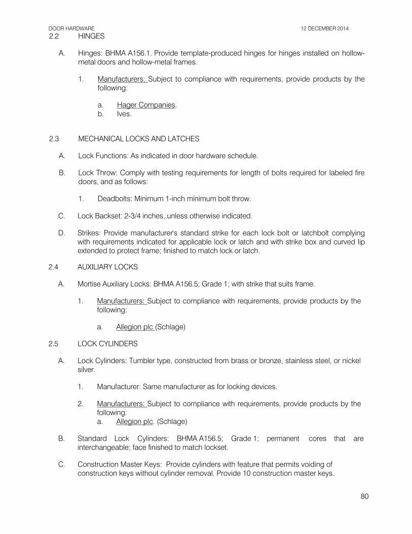
DOOR HARDWARE 12 DECEMBER 2014
2.2 HINGES
A. Hinges: BHMA A156.1. Provide template-produced hinges for hinges installed on hollow- metal doors and hollow-metal frames.
1. Manufacturers: Subject to compliance with requirements, provide products by the
following:
a. Hager Companies. b. Ives.
2.3 MECHANICAL LOCKS AND LATCHES
A. Lock Functions: As indicated in door hardware schedule.
B. Lock Throw: Comply with testing requirements for length of bolts required for labeled fire doors, and as follows:
1. Deadbolts: Minimum 1-inch minimum bolt throw.
C. Lock Backset: 2-3/4 inches, unless otherwise indicated.
D. Strikes: Provide manufacturer's standard strike for each lock bolt or latchbolt complying with requirements indicated for applicable lock or latch and with strike box and curved lip extended to protect frame; finished to match lock or latch.
2.4 AUXILIARY LOCKS
A. Mortise Auxiliary Locks: BHMA A156.5; Grade 1; with strike that suits frame.
1. Manufacturers: Subject to compliance with requirements, provide products by the
following:
a. Allegion plc (Schlage) 2.5 LOCK CYLINDERS
A. Lock Cylinders: Tumbler type, constructed from brass or bronze, stainless steel, or nickel
silver.
1. Manufacturer: Same manufacturer as for locking devices.
2. Manufacturers: Subject to compliance with requirements, provide products by the following: a. Allegion plc. (Schlage)
B. Standard Lock Cylinders: BHMA A156.5; Grade 1; permanent cores that are interchangeable; face finished to match lockset.
C. Construction Master Keys: Provide cylinders with feature that permits voiding of
construction keys without cylinder removal. Provide 10 construction master keys.
80

DOOR HARDWARE 12 DECEMBER 2014
2.6 KEYING
A. Keying System: Factory registered, complying with guidelines in BHMA A156.28,
Appendix A. Incorporate decisions made in keying conference. 1. Existing System:
a. Master key or grand master key locks to County's existing system. b. Re-key County's existing master key system into new keying system.
2. Keyed Alike: Key all cylinders to same change key.
B. Keys: Nickel silver or Brass – confirm with County at time of submittal.
1. Stamping: Permanently inscribe each key with a visual key control number and
include the following notation:
a. Notation: "DO NOT DUPLICATE."
2. Quantity: In addition to one extra key blank for each lock, provide the following:
a. Cylinder Change Keys: Three. b. Master Keys: Five.
2.7 OPERATING TRIM
A. Operating Trim: BHMA A156.6; stainless steel, unless otherwise indicated.
1. Manufacturers: Subject to compliance with requirements, provide products by the following: a. Ives.
2.8 MECHANICAL STOPS AND HOLDERS
A. Wall- and Floor-Mounted Stops: BHMA A156.16; polished cast brass, bronze, or
aluminum base metal. 1. Manufacturers: Subject to compliance with requirements, provide products by the
following: a. Trimco.
2.9 DOOR GASKETING
A. Door Gasketing: BHMA A156.22; resilient or flexible seal strips that are easily replaceable and readily available from stocks maintained by manufacturer.
1. Manufacturers: Subject to compliance with requirements, available manufacturers
offering products that may be incorporated into the Work include, but are not limited to the following:
a. National Guard Products, Inc. b. Pemko Manufacturing Co. c. Zero International, Inc.
81

DOOR HARDWARE 12 DECEMBER 2014
2.10 THRESHOLDS
A. Thresholds: BHMA A156.21; fabricated to full width of opening indicated.
1. Manufacturers: Subject to compliance with requirements, provide products by one of the following:
a. National Guard Products, Inc. b. Pemko Manufacturing Co.
2.11 FABRICATION
A. Base Metals: Produce door hardware units of base metal indicated, fabricated by forming method indicated, using manufacturer's standard metal alloy, composition, temper, and hardness. Furnish metals of a quality equal to or greater than that of specified door hardware units and BHMA A156.18.
B. Fasteners: Provide door hardware manufactured to comply with published templates
prepared for machine, wood, and sheet metal screws. Provide screws that comply with commercially recognized industry standards for application intended, except aluminum fasteners are not permitted. Provide Phillips flat-head screws with finished heads to match surface of door hardware, unless otherwise indicated.
1. Spacers or Sex Bolts: For through bolting of hollow-metal doors. 2. Gasketing Fasteners: Provide noncorrosive fasteners for exterior applications and
elsewhere as indicated.
2.12 FINISHES
A. Provide finishes complying with BHMA A156.18 as indicated in door hardware schedule.
B. Appearance of Finished Work: Noticeable variations in the same piece are not acceptable. Variations in appearance of other components are acceptable if they a re assembled or installed to minimize contrast.
PART 3 - EXECUTION
3.1 EXAMINATION
A. Examine doors and frames, for labeled fire-rated door assembly construction, wall and floor construction, and other conditions affecting performance.
B. Proceed with installation only after unsatisfactory conditions have been corrected.
3.2 PREPARATION
A. Steel Doors and Frames: For surface applied door hardware, drill and tap doors and
82

DOOR HARDWARE 12 DECEMBER 2014
frames according to ANSI/SDI A250.6. 3.3 INSTALLATION
A. Mounting Heights: Mount door hardware units at heights to comply with the following
unless otherwise indicated or required to comply with governing regulations.
1. Standard Steel Doors and Frames: ANSI/SDI A250.8. 2. Deadbolt: install 60” above finish floor.
B. Install each door hardware item to comply with manufacturer's written instructions. Where
cutting and fitting are required to install door hardware onto or into surfaces that are later to be painted or finished in another way, coordinate removal, storage, and reinstallation of surface protective trim units with finishing. Do not install surface-mounted items until finishes have been completed on substrates involved.
1. Set units level, plumb, and true to line and location. Adjust and reinforce
attachment substrates as necessary for proper installation and operation. 2. Drill and countersink units that are not factory prepared for anchorage fasteners.
Space fasteners and anchors according to industry standards.
C. Hinges: Install types and in quantities indicated in door hardware schedule but not fewer than the number recommended by manufacturer for application indicated or one hinge for every 30 inches of door height, whichever is more stringent, unless other equivalent means of support for door, such as spring hinges or pivots, are provided.
D. Lock Cylinders: Install construction cores to secure building and areas during
construction period. 1. Replace construction cores with permanent cores as directed by County.
E. Thresholds: Set thresholds for exterior doors and other doors indicated in full bed of
sealant complying with requirements specified in Section 07 9200 "Joint Sealants."
F. Stops: Provide floor stops for doors unless wall or other type stops are indicated in door hardware schedule. Do not mount floor stops where they will impede traffic.
G. Perimeter Gasketing: Apply to head and jamb, forming seal between door and frame.
H. Door Bottoms: Apply to bottom of door, forming seal with threshold when door is closed.
3.4 ADJUSTING
A. Initial Adjustment: Adjust and check each operating item of door hardware and each door to ensure proper operation or function of every unit. Replace units that cannot be adjusted to operate as intended. Adjust door control devices to comply with referenced accessibility requirements.
3.5 CLEANING AND PROTECTION
A. Clean operating items as necessary to restore proper function and finish.
83

DOOR HARDWARE 12 DECEMBER 2014
B. Provide final protection and maintain conditions that ensure that door hardware is without damage or deterioration at time of Final Completion.
3.6 DOOR HARDWARE SCHEDULE
HW Set 01 Door 01 (RR-Exterior)
3 EA HINGE 3CB1 4.5x4.5 652 IVE
1 EA MORTISE DEADBOLT L9462 626 SCH
1 EA CORE ONLY ( ) 626 ASSA
1 EA PULL VR900LLP 630 IVE
1 EA
1 SET
1 EA
1 EA
STOP
SEALS
DOOR SWEEP
THRESHOLD
1211
700SA
200NA
158A
630
AL
AL
AL
IVE
NGP
NGP
PEM
HW Set 02 Door 02 (Pipe Chase-Exterior)
3 EA HINGE 3CB1 4.5x4.5 652 IVE
1 EA MORTISE DEADBOLT L9463 626 SCH
1 EA CORE ONLY ( ) 626 ASSA
1 EA
1 SET
1 EA
1 EA
PULL
SEALS
DOOR SWEEP
THRESHOLD
VR904LLP
700SA
200NA
158A
630
AL
AL
AL
IVE
NGP
NGP
PEM
END OF SECTION 08 7100
84

12 DECEMBER 2014
THIS PAGE INTENTIONALLY LEFT BLANK
85

MAINTENANCE REPAINTING 12 DECEMBER 2014
SECTION 09 0190.52 - MAINTENANCE REPAINTING
PART 1 - GENERAL
1.1 RELATED DOCUMENTS
A. Drawings and general provisions of the Contract, including General and Supplementary Conditions and Division 01 Specification Sections, apply to this Section.
1.2 SUMMARY
A. Section includes maintenance repainting as follows:
1. Removing existing paint. 2. Patching substrates. 3. Repainting.
B. Related Requirements:
1. Section 01 3516 "Alteration Project Procedures" for general remodeling, renovation,
repair, and maintenance requirements. 2. Section 08 0152.61 “Wood Louver Repairs” for repair of existing wood louvers prior
to repainting.
1.3 DEFINITIONS
A. Gloss Level 1: Not more than 5 units at 60 degrees and 10 units at 85 degrees, according to ASTM D 523.
B. Gloss Level 2: Not more than 10 units at 60 degrees and 10 to 35 units at 85 degrees,
according to ASTM D 523.
C. Gloss Level 3: 10 to 25 units at 60 degrees and 10 to 35 units at 85 degrees, according to ASTM D 523.
D. Gloss Level 4: 20 to 35 units at 60 degrees and not less than 35 units at 85 degrees,
according to ASTM D 523.
E. Gloss Level 5: 35 to 70 units at 60 degrees, according to ASTM D 523.
F. Gloss Level 6: 70 to 85 units at 60 degrees, according to ASTM D 523.
G. Gloss Level 7: More than 85 units at 60 degrees, according to ASTM D 523.
H. Low-Pressure Spray: 100 to 400 psi; 4 to 6 gpm.
I. Medium-Pressure Spray: 400 to 800 psi; 4 to 6 gpm.
86

MAINTENANCE REPAINTING 12 DECEMBER 2014
1.4 SEQUENCING AND SCHEDULING
A. Perform maintenance repainting in the following sequence, which includes work specified in this and other Sections:
1. Dismantle existing surface-mounted objects and hardware. 2. Remove existing paint to the degree required. 3. Apply paint system. 4. Reinstall dismantled surface-mounted objects and hardware as indicated.
1.5 ACTION SUBMITTALS
A. Samples: For each type of paint system and each pattern, color, and gloss. Label each Sample for location and application.
B. Product List: For each paint product indicated, include the following:
1. Cross-reference to paint system and locations of application areas. 2. VOC content.
1.6 MAINTENANCE MATERIAL SUBMITTALS
A. Furnish extra paint materials, from the same production run, that match products applied and that are packaged with protective covering for storage and identified with labels describing contents, including material, finish, source, and location on building.
1. Quantity: Furnish County with not less than 1 gal. of each material and color applied.
1.7 QUALITY ASSURANCE
A. Color Matching: Custom computer-match paint colors to colors indicated in maintenance repainting schedule(s) at the end of Part 3. For colors indicated by a standardized coding system, obtain a color chip for each color indicated.
1.8 DELIVERY, STORAGE, AND HANDLING
A. Store materials not in use in tightly covered containers in well-ventilated areas.
1. Remove rags and waste daily.
1.9 FIELD CONDITIONS
A. Do not apply paint in snow, rain, fog, or mist; when relative humidity exceeds 85 percent; at temperatures less than 5 deg F above the dew point; or to damp or wet surfaces.
1. Painting may continue during inclement weather if surfaces and areas to be painted
are enclosed and heated within temperature limits specified by manufacturer for surface preparation and during paint application and drying periods.
87

MAINTENANCE REPAINTING 12 DECEMBER 2014
PART 2 - PRODUCTS
2.1 PREPARATORY CLEANING MATERIALS
A. Water: Potable.
B. Detergent Solution: Solution prepared by mixing 2 cups of tetrasodium pyrophosphate (TSPP), 1/2 cup of laundry detergent that contains no ammonia, 5 quarts of 5 percent sodium hypochlorite bleach, and 15 quarts of water for every 5 gal. of solution required.
C. Mildewcide: Commercial proprietary mildewcide or a job-mixed solution prepared by
mixing 1/3 cup of household detergent that contains no ammonia, 1 quart of 5 percent sodium hypochlorite bleach, and 3 quarts of water.
D. Abrasives for Ferrous Metal Cleaning: Aluminum oxide paper, emery paper, fine steel
wool, steel scrapers, and steel-wire brushes of various sizes. 2.2 PAINT REMOVERS
A. Alkaline Paste Paint Remover: Manufacturer's standard alkaline paste or gel formulation
for removing paint from masonry, stone, wood, plaster, or metal as required to suit Project; and containing no methylene chloride.
1. Manufacturers: Subject to compliance with requirements, available manufacturers
offering products that may be incorporated into the Work include, but are not limited to the following:
a. American Building Restoration Products, Inc.; 800 Brush Grade. b. Diedrich Technologies, Inc.; a division of Sandell Construction Solutions; 606
Multi-Layer Paint Remover. c. PROSOCO, Inc; Sure Klean Heavy-Duty Paint Stripper.
B. Covered or Skin-Forming Alkaline Paint Remover: Manufacturer's standard covered or skin-forming alkaline paste or gel formulation for removing paint from masonry, stone, wood, plaster, or metal as required to suit Project; and containing no methylene chloride.
1. Products: Subject to compliance with requirements, provide one of the following:
a. American Building Restoration Products, Inc.; Grip 'N Strip 800 Fast Acting. b. Diedrich Technologies, Inc.; a division of Sandell Construction Solutions; 404
Rip-Strip. c. Dumond Chemicals, Inc; Peel Away 1 System.
2.3 PAINT, GENERAL
A. Colors: As indicated with each paint system in maintenance repainting schedule(s) at the
end of Part 3.
88

MAINTENANCE REPAINTING 12 DECEMBER 2014
2.4 PAINT MATERIALS, GENERAL
A. MPI Standards: Provide products that comply with MPI standards indicated and that are
listed in its "MPI Approved Products List."
B. Transition Coat: Paint manufacturer's recommended coating for use where a residual existing coating is incompatible with the paint system.
2.5 PAINT MATERIALS
A. Primers and Sealers:
1. Primer Sealer, Acrylic, Interior/Exterior: MPI #17.
a. Basis-of-Design Product: Glidden Professional “Gripper”.
B. Water-Based Paints:
1. Latex, Exterior Low Sheen (Gloss Levels 3-4): MPI #15.
a. Basis-of-Design Product: Glidden Professional “Fortis 450 – Satin”.
C. Metal-Patching Compound: Two-part, polyester-resin, metal-patching compound; knife-
grade formulation as recommended in writing by manufacturer for type of metal repair indicated, tooling time required for the detail of work, and site conditions. Compound shall be produced for filling metal that has deteriorated from corrosion. Filler shall be capable of filling deep holes and spreading to feather edge.
D. Cementitious Patching Compounds: Cementitious patching compounds and repair
materials specifically manufactured for filling cementitious substrates and for sanding or tooling prior to repainting; formulation as recommended in writing by manufacturer for type of cementitious substrate indicated, exposure to weather and traffic, the detail of work, and site conditions.
PART 3 - EXECUTION
3.1 PROTECTION
A. Comply with each manufacturer's written instructions for protecting building and other
surfaces against damage from exposure to its products. Prevent chemical solutions from coming into contact with people, motor vehicles, landscaping, buildings, and other surfaces that could be harmed by such contact.
1. Cover adjacent surfaces with materials that are proven to resist chemical solutions
being used unless the solutions will not damage adjacent surfaces. Use protective materials that are UV resistant and waterproof. Apply masking agents to comply with manufacturer's written instructions. Do not apply liquid masking agent to painted or porous surfaces. When no longer needed, promptly remove masking to prevent adhesive staining.
89

MAINTENANCE REPAINTING 12 DECEMBER 2014
2. Do not apply chemical solutions during winds of sufficient force to spread them to unprotected surfaces.
3. Neutralize and collect alkaline and acid wastes before disposal. 4. Dispose of runoff from operations by legal means and in a manner that prevents
soil erosion, undermining of paving and foundations, damage to landscaping, and water penetration into building interiors.
3.2 MAINTENANCE REPAINTING, GENERAL
A. Execution of the Work: In repainting surfaces, disturb them as minimally as possible and as follows:
1. Remove failed coatings and corrosion and repaint. 2. Verify that substrate surface conditions are suitable for repainting. 3. Allow other trades to repair items in place before repainting.
B. Mechanical Abrasion: Where mechanical abrasion is needed for the work, use gentle
methods, such as scraping and lightly hand sanding, that will not abrade softer substrates, reducing clarity of detail.
C. Heat Processes: Do not use torches, heat guns, or heat plates.
3.3 EXAMINATION
A. Examine substrates and conditions, with Installer present, for compliance with requirements for maximum moisture content and other conditions affecting performance of painting work. Comply with paint manufacturer's written instructions for inspection.
B. Maximum Moisture Content of Substrates: Do not begin application of coatings unless
moisture content of exposed surface is below the maximum value recommended in writing by paint manufacturer and not greater than the following maximum values when measured with an electronic moisture meter appropriate to the substrate material:
1. Concrete: 12 percent. 2. Masonry (Clay and CMU): 12 percent. 3. Wood: 15 percent.
C. Alkalinity: Do not begin application of coatings unless surface alkalinity is within range
recommended in writing by paint manufacturer. Conduct alkali testing with litmus paper on exposed plaster, cementitious, and masonry surfaces.
D. After completing examination of substrates begin coating application only after
unsatisfactory conditions have been corrected and surfaces are dry. Beginning coating application constitutes Contractor’s acceptance of substrates and conditions.
3.4 PREPARATORY CLEANING
A. General: Use the gentlest, appropriate method necessary to clean surfaces in preparation for painting. Clean all surfaces, corners, contours, and interstices.
90

MAINTENANCE REPAINTING 12 DECEMBER 2014
B.
C. Detergent Cleaning: Wash surfaces by hand using clean rags, sponges, and bristle brushes. Scrub surface with detergent solution and bristle brush until soil is thoroughly dislodged and can be removed by rinsing. Use small brushes to remove soil from joints and crevices. Rinse with water applied by clean rags or sponges.
D. Solvent Cleaning: Use solvent cleaning to remove oil, grease, smoke, tar, and asphalt
from painted or unpainted surfaces before other preparation work. Wipe surfaces with solvent using clean rags and sponges. Do not use solvents, including primer thinner and turpentine, which leave residue.
E. Mildew: I f found, clean off existing mildew, algae, moss, plant material, and other debris
by scrubbing with bristle brush or sponge and detergent solution. Scrub mildewed areas with mildewcide. Rinse with water applied by clean rags or sponges.
F. Mechanical Rust Removal:
1. Remove rust to bright metal with specified abrasives for ferrous-metal cleaning. 2. Wipe off residue with mineral spirits and either steel wool or soft rags. 3. When dry, prime immediately to prevent rust.
3.5 PAINT REMOVAL
A. General: Remove paint where indicated. Where cleaning methods have been attempted and further removal of the paint is required because of incompatible or unsatisfactory surfaces for repainting, remove paint to extent required by conditions.
1. Application: Apply paint removers according to paint-remover manufacturer's
written instructions. Do not allow paint removers to remain on surface for periods longer than those indicated or recommended in writing by manufacturer.
2. Brushes: Use brushes that are resistant to chemicals being used. Do not use wire
brushes on wood.
3. Spray Equipment: Use spray equipment that provides controlled application at volume and pressure indicated, measured at nozzle. Equip units with pressure gages.
B. Paint Removal with Hand Tools: Remove paint manually using hand-held scrapers,
brushes, sandpaper, and metallic wool as appropriate for the substrate material.
C. Paint Removal with Alkaline Paste Paint Remover: Follow process recommended in writing by manufacturer.
D. Paint Removal with Covered or Skin-Forming Alkaline Paint Remover: Follow process
recommended in writing by manufacturer.
3.6 SUBSTRATE REPAIR
A. General: Repair substrate surface defects that are inconsistent with the surface 91

MAINTENANCE REPAINTING 12 DECEMBER 2014
appearance of adjacent materials and finishes.
B. Wood Substrate:
1. Repair wood defects including dents and gouges more than 1/4 inch in size and all holes and cracks by filling with wood-patching compound and sanding smooth. Reset or remove protruding fasteners.
2. Where existing paint is allowed to remain, sand irregular buildup of paint, runs, and sags to achieve a uniformly smooth surface.
C. Cementitious Material Substrate:
1. General: Repair defects including dents and chips more than 1/2 inch in size and
all holes and cracks by filling with cementitious patching compound and sanding smooth. Remove protruding fasteners.
2. Concrete, Cement Plaster, and Other Cementitious Products: Remove efflorescence, chalk, dust, dirt, grease, oils, and release agents. If surfaces are too alkaline to paint, correct this condition before painting.
D. Metal Substrate:
1. Preparation: Treat repair locations by wire-brushing and solvent cleaning. Use mechanical rust removal method to clean off rust.
2. Defects in Metal Surfaces: Repair non-load-bearing defects in existing metal surfaces, including dents and gouges more than 1/8 inch deep or 1/2 inch across and all holes and cracks by filling with metal-patching compound and sanding smooth. Remove burrs and protruding fasteners.
3. Priming: Prime iron and steel surfaces immediately after repair to prevent flash rusting. Stripe paint corners, crevices, bolts, welds, and sharp edges. Apply two coats to surfaces that are inaccessible after completion of the Work.
3.7 PAINT APPLICATION, GENERAL
A. Comply with manufacturers' written instructions for application methods unless otherwise indicated in this Section.
B. Prepare surfaces to be painted according to the Surface-Preparation Schedule and with
manufacturer's written instructions for each substrate condition.
C. Apply a transition coat over incompatible existing coatings.
D. Metal Substrate: Stripe paint corners, crevices, bolts, welds, and sharp edges before applying full coat. Apply two coats to surfaces that are inaccessible after completion of the Work. Tint stripe coat different than the main coating and apply with brush.
E. Blending Painted Surfaces: When painting new substrates patched into existing surfaces
or touching up missing or damaged finishes, apply coating system specified for the specific substrate. Apply final finish coat over entire surface from edge to edge and corner to corner.
92

MAINTENANCE REPAINTING 12 DECEMBER 2014
3.8 CLEANING AND PROTECTION
A. At end of each workday, remove rubbish, empty cans, rags, and other discarded materials
from Project site.
B. After completing paint application, clean spattered surfaces. Remove spattered paints by washing, scraping, or other methods. Do not scratch or damage adjacent finished surfaces.
C. Protect work of other trades against damage from paint application. Correct damage to
work of other trades by cleaning, repairing, replacing, and refinishing, as approved by County.
3.9 SURFACE-PREPARATION SCHEDULE
A. General: Before painting, prepare surfaces for painting according to applicable
requirements specified in this schedule.
1. Examine surfaces and evaluate condition according to paragraphs below. 2. Where existing degree of soiling prevents examination, preclean surface and allow
it to dry before making an evaluation. 3. Repair substrate defects according to "Substrate Repair" Article.
B. Surface Preparation for MPI DSD 0 Degree of Surface Degradation:
1. Surface Condition: Existing paint film in good condition and tightly adhered. 2. Paint Removal: Not required. 3. Preparation for Painting: Wash surface by detergent cleaning; use solvent cleaning
where needed. Roughen or degloss cleaned surfaces to ensure paint adhesion according to paint manufacturer's written instructions.
C. Surface Preparation for MPI DSD 1 Degree of Surface Degradation:
1. Surface Condition: Paint film cracked or broken but adhered. 2. Paint Removal: Scrape by hand-tool cleaning methods to remove loose paint until
only tightly adhered paint remains. 3. Preparation for Painting: Wash surface by detergent cleaning; use other cleaning
methods for small areas of bare substrate if required. Roughen, degloss, and sand cleaned surfaces to ensure paint adhesion and a smooth finish according to paint manufacturer's written instructions.
D. Surface Preparation for MPI DSD 2 Degree of Surface Degradation:
1. Surface Condition: Paint film loose, flaking, or peeling. 2. Paint Removal: Remove loose, flaking, or peeling paint film by hand-tool or
chemical paint-removal methods. 3. Preparation for Painting: Wash surface by detergent cleaning; use solvent cleaning
where needed. Use other cleaning methods for small areas of bare substrate if required. Sand surfaces to smooth remaining paint film edges. Prepare bare
93

MAINTENANCE REPAINTING 12 DECEMBER 2014
cleaned surface to be painted according to paint manufacturer's written instructions.
E. Surface Preparation for MPI DSD 3 Degree of Surface Degradation:
1. Surface Condition: Paint film severely deteriorated and surfaces indicated to have paint completely removed.
2. Paint Removal: Completely remove paint film by hand-tool or chemical paint- removal methods. Remove rust.
3. Preparation for Painting: Prepare cleaned surface according to paint manufacturer's written instructions.
F. Surface Preparation for MPI DSD 4 Degree of Surface Degradation:
1. Surface Condition: Missing material, small holes and openings, and deteriorated or
corroded substrate. 2. Substrate Preparation: Repair, replace, and treat substrate according to "Substrate
Repair" Article and requirements in other Specification Sections. 3. Preparation for Painting: Sand substrate surfaces to smooth remaining paint film
edges and prepare according to paint manufacturer's written instructions. Remove rust.
4. Painting: Paint as required for MPI DSD 2 degree of surface degradation.
3.10 EXTERIOR MAINTENANCE REPAINTING SCHEDULE
A. Wood Eave Overhangs & Roof Fascia:
1. Latex System: MPI REX 6.2A system.
a. Prime Coat: For MPI DSD 1 degree of surface degradation, touch up with topcoat.
b. Prime Coat: For MPI DSD 2 degree of surface degradation, spot prime with Primer.
c. Intermediate Coat: Latex, exterior, matching topcoat. d. Topcoat: Latex, exterior, low sheen (Gloss Levels 3-4), MPI #15. e. Color: Match existing. Parks Department records indicate “Chesterfield
Brown” which is a PPG Porter color. Verify in field, provide submittal.
B. Wood Louver Frames & Trim:
1. Latex System: MPI REX 6.3A system.
a. Prime Coat: For MPI DSD 1 degree of surface degradation, touch up with topcoat.
b. Prime Coat: For MPI DSD 2 degree of surface degradation, spot prime with Primer, Alkyd for Exterior Wood, MPI #5.
c. Prime Coat: For MPI DSD 3 degree of surface degradation, fully prime coat with Primer, Alkyd for Exterior Wood, MPI #5.
d. Intermediate Coat: Latex, exterior, matching topcoat. e. Topcoat: Latex, exterior, low sheen (Gloss Levels 3-4), MPI #15. f. Colors:
1) At exterior: match ICI color “Tantalizing Tan” #00YY 35/180
94

MAINTENANCE REPAINTING 12 DECEMBER 2014
2) At interior: match ICI color “Antique White” RM#A0065
C. CMU Substrates (interior and exterior):
1. Latex System MPI EXT 4.2A:
a. Prime Coat: For MPI DSD 1 degree of surface degradation, touch up with topcoat.
b. Prime Coat: For MPI DSD 2 degree of surface degradation, spot prime with Primer.
c. Intermediate Coat: Latex, exterior, matching topcoat. d. Topcoat: Latex, exterior, low sheen (Gloss Levels 3-4), MPI #15. e. Color: Match ICI color “Swiss Coffee” #A0073.
D. Galvanized-Metal Substrates:
1. Latex System MPI EXT 5.3H:
a. Prime Coat: Primer, galvanized, water based, MPI #134. b. Intermediate Coat: Latex, exterior, matching topcoat. c. Topcoat: Latex, exterior, low sheen (MPI Gloss Level 3-4), MPI #15. d. Colors
1) Doors & Frames Exterior side: Match ICI color “Tantalizing Tan”
#00YY 35/180. 2) Doors & Frames Interior side: Match ICI color “Antique White”
RM#A0065 3) Conduits, Misc. j-boxes, etc.: Match adjacent surface.
E. Wood Ceilings:
1. Latex System over Latex Primer: MPI RIN 6.2D system.
a. Prime Coat: For MPI DSD 1 degree of surface degradation, touch up with topcoat.
b. Prime Coat: For MPI DSD 2 degree of surface degradation, spot prime with Primer.
c. Prime Coat: For MPI DSD 3 degree of surface degradation, fully prime coat with Primer.
d. Intermediate Coat: Latex, interior, matching topcoat. e. Topcoat: Latex, MPI#15. f. Color: Match ICI color “Tantalizing Tan” #00YY 35/180.
END OF SECTION 09 0190.52
95

RESINOUS FLOORING 12 DECEMBER 2014
SECTION 09 6723 - RESINOUS FLOORING
PART 1 - GENERAL
1.1 SECTION INCLUDES
A. This section includes the following resinous flooring systems:
1. RES-1: Prime Cast 2611, epoxy vinyl fleck flooring system with non-yellowing hydrogenated epoxy and integrated anti-microbial finish.
1.2 REFERENCE STANDARDS
A. ASTM E 1907 Standard Guide to Methods of Evaluating Moisture Conditions of Concrete Floors to Receive Resilient Floor Coverings.
B. ASTM D 4263 Standard Test Method for Indicating Moisture in Concrete by the Plastic
Sheet Method.
C. ASTM F 1869 Standard Test Method for Measuring Moisture Vapor Emission Rate of Concrete Sub-floor by Using Anhydrous Calcium Chloride.
D. ASTM F 2170 Standard Test Method for Determining Relative Humidity in Concrete Slabs
Using in situ Probes.
E. ASTM D 4501 Standard Test Method for Shear Strength of Adhesive Bonds Between Rigid Substrates by the Block-Shear Method.
F. ASTM F 710 Standard Practice for Preparing Concrete Floors to Receive Resilient Flooring.
G. ASTM C 579 Standard Test Methods for Compressive Strength of Chemical- Resistant
Mortars, Grouts, Monolithic Surfacings, and Polymer Concretes.
H. ICRI No. 03732 Selecting and Specifying Concrete Surface Preparation for Sealers, Coatings, and Polymer Overlays, CSP 1-9.
1.3 ADMINISTRATIVE REQUIREMENTS
A. Pre-installation Meeting: Prior to the installation of the seamless system, meeting shall be held at the project site with the installer, and the County’s representative. Topics to be discussed shall include, but not be limited to:
1. Planned start and completion timing for each mobilization. 2. Existing slab condition. 3. Curing time and methods.
96

RESINOUS FLOORING 12 DECEMBER 2014
1.4 SUBMITTALS
A. Product Data: For each product indicated, include manufacturer’s technical data,
application instructions, and recommendations for each product component.
B. Shop Drawings:
1. Provide floor plans matching Architectural Plans, indicating extent of each resinous floor/wall system, including type, color and pattern, degree of slip-resistance, and dimensioned locations of control joints, seams, and terminations.
2. Provide details indicating terminations at walls, door frames, etc.
C. Samples: For each resinous system, provide samples applied to a rigid backing, minimum size 4 inches x 4 inches. Samples will be submitted to the County for approving both color and texture prior to installing specified systems.
D. Warranty: Manufacturer shall provide a specimen copy of warranty.
1.5 QUALITY ASSURANCE
A. Installer Qualifications: Engage an experienced installer/company who has a minimum of 10 years of experience in applying the resinous flooring specified herein, including similar job sizes and complexity.
B. Source Limitations: Obtain all resinous flooring materials, including waterproofing membranes, grouts, resins, curing agents, grout coats, aggregates, topcoats, patching and fill material, joint sealants, and repair materials from a single Manufacturer.
C. Manufacturer Responsibilities:
1. Supervision: The installer of the coating system shall contact the material
manufacturer during the bidding phase of the project and shall include in the cost of this work, manufacturer’s field engineering services as specified below.
2. Material Manufacturer shall be responsible for the review of the project conditions before product installation, including but not limited to project climate, acceptable temperature of substrate and air, acceptable humidity levels of air, acceptable moisture content of substrates to be coated and all conditions that are necessary for optimum product performance. The manufacturer’s field engineer shall verify that all conditions are acceptable prior to commencement of work.
3. The manufacturer’s field representative shall submit through the Contractor written approvals of the proposed coating system including manufacturer’s recommended applicator, manufacturer’s recommended application procedures, and manufacturer’s recommended surface preparation.
4. The manufacturer is solely liable for any warranty claims resulting from product failure, whether caused by defective product or improper installation for a period of 1 year. See warranty section: 1.8 for clarification.
5. The materials manufacturer’s representative must be present on site for the pre- installation site conditions evaluation, for the duration of the surface preparation and for all phases of the installation of the specified resinous coating system. Installer’s bid shall include the cost of the manufacturer’s field services as specified above.
97

RESINOUS FLOORING 12 DECEMBER 2014
1.6 DELIVERY, STORAGE, & HANDLING
A. Materials shall be delivered in original packages and containers, with seals unbroken, bearing manufacturer's labels indicating brand name and directions for storage and mixing with other components.
B. Storage of materials shall comply with all fire and safety regulations.
1.7 PROJECT CONDITIONS
A. Environmental Limitations: Comply with resinous flooring manufacturer's written instructions for substrate temperature, ambient temperature, moisture, ventilation, and other conditions affecting resinous flooring application.
B. Conditions of Substrates:
1. Floor slabs: Concrete must be sound and meet all requirements as outlined in
Section 3.1 B.
C. Lighting: Provide permanent lighting or simulate permanent lighting conditions during resinous floor/wall application.
D. Close spaces to traffic during resinous flooring application and for not less than 24 hours
after application, unless manufacturer recommends a longer period. 1.8 WARRANTY
A. Manufacturer shall furnish a single, written warranty covering 100% of the material and
labor costs protecting the County from delamination, disbondment, or other failures due to defects in product or poor installation for a period of one year from date of installation.
1. Issuance of warranty shall be a condition precedent to receipt of final payment by
the Installer. 2. Extent of warranty shall be limited to the repair or replacement of defective surfaces
at no cost to the County, and for any damage directly resulting from such defects during the warranty period. The warranty shall not include any remedy for defects caused by abuse, improper maintenance or operation, or by normal wear and tear.
3. Warranty must be supplied by Manufacturer of the installed system. Joint warranties not acceptable.
PART 2 - PRODUCTS
2.1 MANUFACTURERS
A. Manufacturer of Basis of Design: Prime Coat Coating Systems, 847-362-5111; email:
98
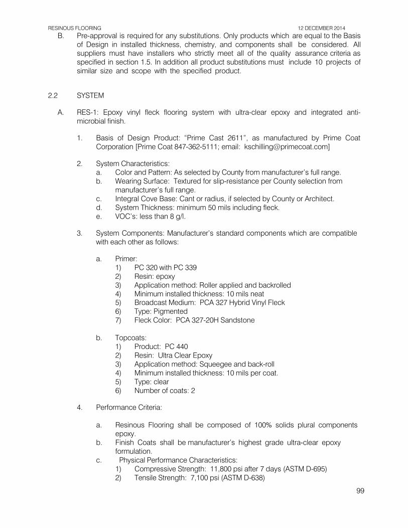
RESINOUS FLOORING 12 DECEMBER 2014
B. Pre-approval is required for any substitutions. Only products which are equal to the Basis of Design in installed thickness, chemistry, and components shall be considered. All suppliers must have installers who strictly meet all of the quality assurance criteria as specified in section 1.5. In addition all product substitutions must include 10 projects of similar size and scope with the specified product.
2.2 SYSTEM
A. RES-1: Epoxy vinyl fleck flooring system with ultra-clear epoxy and integrated anti-
microbial finish.
1. Basis of Design Product: “Prime Cast 2611”, as manufactured by Prime Coat Corporation [Prime Coat 847-362-5111; email: [email protected]]
2. System Characteristics:
a. Color and Pattern: As selected by County from manufacturer’s full range. b. Wearing Surface: Textured for slip-resistance per County selection from
manufacturer’s full range. c. Integral Cove Base: Cant or radius, if selected by County or Architect. d. System Thickness: minimum 50 mils including fleck. e. VOC’s: less than 8 g/l.
3. System Components: Manufacturer’s standard components which are compatible
with each other as follows:
a. Primer: 1) PC 320 with PC 339 2) Resin: epoxy 3) Application method: Roller applied and backrolled 4) Minimum installed thickness: 10 mils neat 5) Broadcast Medium: PCA 327 Hybrid Vinyl Fleck 6) Type: Pigmented 7) Fleck Color: PCA 327-20H Sandstone
b. Topcoats:
1) Product: PC 440 2) Resin: Ultra Clear Epoxy 3) Application method: Squeegee and back-roll 4) Minimum installed thickness: 10 mils per coat. 5) Type: clear 6) Number of coats: 2
4. Performance Criteria:
a. Resinous Flooring shall be composed of 100% solids plural components
epoxy. b. Finish Coats shall be manufacturer’s highest grade ultra-clear epoxy
formulation. c. Physical Performance Characteristics:
1) Compressive Strength: 11,800 psi after 7 days (ASTM D-695) 2) Tensile Strength: 7,100 psi (ASTM D-638)
99

RESINOUS FLOORING 12 DECEMBER 2014
3) Tensile Elongation: 10.7% (ASTM D-638) 4) Flexural Strength: 12,500 psi (ASTM D-790) 5) Flexural Modulus of Elasticity: 3.7 x 10⁵psi (ASTM D-790) 6) Hardness: 70-75 (ASTM D-2240/Shore D Durometer) 7) Bond Strength: >400 psi (100% concrete failure) 8) Indentation: No indentation (MIL-D-3134F) 9) Abrasion Resistance: 0.04 gm max weight loss (ASTM D-4060, Taber
Abrader). 10) Flammability: Self-extinguishing (ASTM D-635) 11) Water Absorption: 0.1% (ASTM C-413) 12) Heat Resistance Limitation: 140º F/60º C (for continuous exposure)
200º F/ 93ºC (for intermittent spills)
2.3 ACCESSORY MATERIALS
A. Patching and Fill Material: All non-moving joints and cracks shall be routed out and filled with PC 100 mixed with Cabosil to make a thixotropic patching compound.
B. Joint Sealants: All moving joints shall not be coated with specified coating system. After
the specified coating system has been installed, fill moving joints with PC 610 Joint Coat. PART 3 - EXECUTION
3.1 EXAMINATION
A. Mandatory Testing of Floor Slabs:
1. Prior to the installation of flooring, it is mandatory that all surfaces are tested for
moisture content, pH, and alkalinity levels that would be detrimental to the adhesion of coating materials. For tests to be accurate, temperatures and humidity levels should be stabilized for a minimum of 72 hours. NOTE: TESTING PERFORMED BY ANY METHOD IN UNCONDITIONED SPACES WILL NOT YIELD CONSISTENT RESULTS.
a. Calcium Chloride Tests per ASTM F 1869 b. Relative Humidity Testing per ASTM F 2170
2. Do not proceed with installation if moisture levels exceed 5% or 3 lbs. per 1,000 sf
per 24 hours or if ambient temperature is less than 5°F above dew point unless approved by material manufacturer.
3.2 PREPARATION
A. General: Prepare and clean substrates in accordance with manufacturer’s written
instructions for substrate indicated. Provide clean, dry, and neutral pH substrate for resinous floor/wall application.
100

RESINOUS FLOORING 12 DECEMBER 2014
B. Concrete Floors: Provide sound concrete surfaces free of laitance, glaze, effervescence,
curing compounds, form-release agents, dust, dirt, grease, oil, and other contaminants incompatible with resinous flooring. Floor slabs shall be prepared as follows:
1. Diamond grind to expose concrete matrix and profile concrete floor surfaces to
a classification of ICRI CSP2. 2. Rinse and dry all floor surfaces scheduled to receive high performance floor system
finish prior to commencement of resinous flooring application. 3. Remove and legally dispose of all debris and contaminants produced by the
grinding process.
3.3 INSTALLATION
A. General: Apply components of resinous flooring system according to manufacturer’s written instructions to produce a uniform, monolithic wearing surface at the specified thickness.
1. At substrate control, isolation, and expansion joints, provide joint as necessary in
resinous flooring in compliance with manufacturer’s directions and engineering details for each joint type.
a. Apply backer rod and elastomeric joint filler as recommended by the coating
manufacturer into isolation or expansion joints.
B. Installation of RES-1
1. Apply one full coat of PC 320 with PC 339 color pack at 10 mils. 2. While resin is wet broadcast to rejection PCA 327 Fleck into open resin. Allow to
dry. 3. Using a steel floor scraper or steel flat blade go over the entire floor surface to
knock off and remove protruding edges of vinyl fleck. 4. Apply one full coat of PC 440 mixed liquids at 10 mils DFT. Allow to cure. 5. Using a steel floor scraper or steel flat blade go over the entire floor surface to
knock off and remove protruding edges of vinyl fleck. Remove all surface containments.
6. After topcoat has cured but prior to 24 hours, apply a second coat of PC 440 mixed liquids at 10 mils DFT. Allow to cure.
7. Protect floor from traffic for a minimum of 48 hours. 8. Comply with recommendations of manufacturer of flooring system for drying times
between primer and succeeding coats. 9. Finish product shall be uniform in color and texture and free of skipped or missed
areas. Slight variations in texture are acceptable.
3.4 FIELD QUALITY CONTROL
A. Manufacturer’s Field Service:
1. Manufacturer will send qualified technical representative to the Project site for the
following purposes:
101

RESINOUS FLOORING 12 DECEMBER 2014
a. Attend testing procedures with the County’s Representative, and the
Installer. b. Ascertain that each component of the resinous flooring system is being
installed in accordance with manufacturer’s directions.
3.5 CURING
A. Cure resinous flooring components according to manufacturer's written instructions.
Prevent contamination during curing processes.
3.6 CLEANING
A. Work area shall be left clean with all trash, equipment, and leftovers removed.
B. Floor may be cleaned prior to final inspection, providing complete curing has taken place. Generally, non-chlorinated detergents should be used for the first month after curing is complete.
3.7 PROTECTION
A. Protection from damage and wear during the construction process is recommended.
Comply with manufacturer’s recommendations for protective materials and their method of application. Remove temporary protection prior to final inspection. Removal of this material is not the responsibility of the Installer.
END OF SECTION 09 6723
102

PANEL SIGNAGE 12 DECEMBER 2014
SECTION 10 1423 - PANEL SIGNAGE
PART 1 - GENERAL
1.1 RELATED DOCUMENTS
A. Drawings and general provisions of the Contract, including General and Supplementary Conditions and Division 01 Specification Sections, apply to this Section.
1.2 SUMMARY
A. Section Includes:
1. Panel signs.
B. Related Requirements:
1. Section 01 5639 "Temporary Tree and Plant Protection" for temporary protection- zone signage.
1.3 DEFINITIONS
A. Accessible: In accordance with the accessibility standard.
1.4 ACTION SUBMITTALS
A. Product Data: For each type of product.
B. Shop Drawings: For panel signs.
1. Include fabrication and installation details and attachments to other work. 2. Show sign mounting heights, locations of supplementary supports to be provided
by others, and accessories. 3. Show message list, typestyles, graphic elements, including raised characters and
Braille, and layout for each sign at least half size.
C. Sign Schedule: Use same designations specified or indicated on Drawings or in a sign schedule.
1.5 CLOSEOUT SUBMITTALS
A. Maintenance Data: For Panel Signs to include in maintenance manuals 1.6 WARRANTY
A. Special Warranty: Manufacturer agrees to repair or replace components of signs that fail
in materials or workmanship within specified warranty period.
103

PANEL SIGNAGE 12 DECEMBER 2014
1. Failures include, but are not limited to, the following: a. Deterioration of finishes beyond normal weathering. b. Deterioration of embedded graphic image. c. Separation or delamination of sheet materials and components.
2. Warranty Period: Five years from date of Final Completion. PART 2 – PRODUCTS 2.1 SIGNS
A. Manufacturers: Subject to compliance with requirements, available manufacturers
offering products that may be incorporated into the Work include, but are not limited to the following:
1. Cosco. 2. InPro Corporation (IPC).
B. Panel Sign: Sign with smooth, uniform surfaces; with message and characters having uniform faces, sharp corners, and precisely formed lines and profiles; and as follows:
1. Basis-of-Design Product: ¼” thick exterior grade photopolymer with integral raised
text & graphics and integral contracted Grade 2 Braille (per CBC Chapter 11B).
2. Sign-Panel Perimeter: Finish edges smooth.
a. Edge Condition: Bevel cut or rounded (eased). b. Corner Condition in Elevation: Rounded.
3. Mounting: with adhesive.
4. Text and Typeface: Accessible raised characters and Braille typeface as indicated
by manufacturer's designation.
2.2 ACCESSORIES
A. Fasteners and Anchors: Manufacturer's standard as required for secure anchorage of signage, noncorrosive and compatible with each material joined, and complying with the following: 1. Use concealed fasteners and anchors unless indicated to be exposed.
B. Adhesive: As recommended by sign manufacturer.
2.3 FABRICATION
A. General: Provide manufacturer's standard sign assemblies according to requirements
indicated. 1. Preassemble signs and assemblies in the shop to greatest extent possible.
Disassemble signs and assemblies only as necessary for shipping and handling limitations. Clearly mark units for reassembly and installation; apply markings in locations concealed from view after final assembly.
104

PANEL SIGNAGE 12 DECEMBER 2014
2. Mill joints to a tight, hairline fit. Form assemblies and joints exposed to weather to resist water penetration and retention.
3. Comply with AWS for recommended practices in welding and brazing. Provide welds and brazes behind finished surfaces without distorting or discoloring exposed side. Clean exposed welded and brazed connections of flux, and dress exposed and contact surfaces.
4. Conceal connections if possible; otherwise, locate connections where they are inconspicuous.
5. Internally brace signs for stability and for securing fasteners. 6. Provide rebates, lugs, and brackets necessary to assemble components and to
attach to existing work. Drill and tap for required fasteners. Use concealed fasteners where possible; use exposed fasteners that match sign finish.
B. Subsurface-Applied Graphics: Apply graphics to back face of clear face-sheet material to
produce precisely formed image. Image shall be free of rough edges.
2.4 GENERAL FINISH REQUIREMENTS
A. Protect mechanical finishes on exposed surfaces from damage by applying a strippable, temporary protective covering before shipping.
B. Appearance of Finished Work: Noticeable variations in same piece are not acceptable.
Variations in appearance of adjoining components are acceptable if they are within the range of approved Samples and are assembled or installed to minimize contrast.
PART 3 - EXECUTION 3.1 EXAMINATION
A. Examine substrates, areas, and conditions, with Installer present, for compliance with
requirements for installation tolerances and other conditions affecting performance of signage work.
B. Verify that sign-support surfaces are within tolerances to accommodate signs without
gaps or irregularities between backs of signs and support surfaces unless otherwise indicated.
C. Proceed with installation only after unsatisfactory conditions have been corrected.
3.2 INSTALLATION
A. General: Install signs using mounting methods indicated and according to manufacturer's
written instructions.
1. Install signs level, plumb, true to line, and at locations and heights indicated, with sign surfaces free of distortion and other defects in appearance.
2. Install signs so they do not protrude or obstruct according to the accessibility standard.
3. Before installation, verify that sign surfaces are clean and free of materials or debris that would impair installation.
105

PANEL SIGNAGE 12 DECEMBER 2014
B. Room-Identification Signs and Other Accessible Signage: Install in locations on walls as indicated and according to accessibility standard.
C. Mounting Methods:
1. Adhesive: Clean bond-breaking materials from substrate surface and remove loose
debris. Apply linear beads or spots of adhesive symmetrically to back of sign and of suitable quantity to support weight of sign after cure without slippage. Keep adhesive away from edges to prevent adhesive extrusion as sign is applied and to prevent visibility of cured adhesive at sign edges. Place sign in position, and push to engage adhesive. Temporarily support sign in position until adhesive fully sets.
3.3 ADJUSTING AND CLEANING
A. Remove and replace damaged or deformed signs and signs that do not comply with
specified requirements. Replace signs with damaged or deteriorated finishes or components that cannot be successfully repaired by finish touchup or similar minor repair procedures.
B. Remove temporary protective coverings and strippable films as signs are installed.
C. On completion of installation, clean exposed surfaces of signs according to manufacturer's written instructions, and touch up minor nicks and abrasions in finish. Maintain signs in a clean condition during construction and protect from damage until acceptance by County.
END OF SECTION 10 1423
106

12 DECEMBER 2014
THIS PAGE INTENTIONALLY LEFT BLANK
107

STAINLESS-STEEL TOILET COMPARTMENTS 12 DECEMBER 2014
SECTION 10 2113.15 - STAINLESS-STEEL TOILET COMPARTMENTS
PART 1 - GENERAL
1.1 RELATED DOCUMENTS
A. Drawings and general provisions of the Contract, including General and Supplementary Conditions and Division 01 Specification Sections, apply to this Section.
1.2 SUMMARY
A. Section includes stainless-steel toilet compartments configured as toilet enclosures.
B. Related Requirements:
1. Section 10 2800 "Toilet, Bath, and Laundry Accessories" for toilet tissue dispensers, grab bars, purse shelves, and similar accessories mounted on toilet compartments.
1.3 ACTION SUBMITTALS
A. Product Data: For each type of product.
1. Include construction details, material descriptions, dimensions of individual
components and profiles, and finishes for toilet compartments.
B. Shop Drawings: For toilet compartments.
1. Include plans, elevations, sections, details, and attachment details. 2. Show locations of reinforcements for compartment-mounted grab bars and
locations of blocking for surface-mounted toilet accessories. 3. Show locations of centerlines of toilet fixtures. 4. Show locations of floor drains as verified in the field. 5. Show overhead support or bracing locations.
C. Samples for Verification: For the following products, in manufacturer's standard sizes
unless otherwise indicated: 1. Cut sheets each type of material, color, and finish required for toilet
compartments, hardware and accessory.
1.4 CLOSEOUT SUBMITTALS
A. Maintenance Data: For toilet compartments to include in maintenance manuals.
1.5 PROJECT CONDITIONS
A. Field Measurements: Verify actual locations of toilet fixtures, walls, columns, ceilings, and other construction contiguous with toilet compartments by field measurements before fabrication.
108

STAINLESS-STEEL TOILET COMPARTMENTS 12 DECEMBER 2014
PART 2 - PRODUCTS
2.1 PERFORMANCE REQUIREMENTS
A. Regulatory Requirements: Comply with applicable provisions in the U.S. Architectural &
Transportation Barriers Compliance Board's ADA-ABA Accessibility Guidelines for Buildings and Facilities and ICC A117.1 and CBC Chapter 11B for toilet compartments designated as accessible.
2.2 STAINLESS-STEEL TOILET COMPARTMENTS
A. Manufacturers: Subject to compliance with requirements, provide products by one of the
following:
1. Accurate Partitions Corp.; ASI Group. 2. Bradley Corporation. 3. Global Partitions; ASI Group.
B. Toilet-Enclosure Style: Overhead braced.
C. Door, Panel, and Pilaster Construction: Seamless, metal facing sheets pressure laminated to core material; with continuous, interlocking molding strip or lapped-and- formed edge closures; corners secured by welding or clips and exposed welds ground smooth. Exposed surfaces shall be free of pitting, seam marks, roller marks, stains, discolorations, telegraphing of core material, or other imperfections.
1. Core Material: Manufacturer's standard sound-deadening honeycomb of resin-
impregnated kraft paper in thickness required to provide finished thickness of 1 inch for doors and panels and 1-1/4 inches for pilasters.
2. Tapping Reinforcement: Provide concealed reinforcement for tapping (threading) at locations where machine screws are used for attaching items to units.
D. Facing Sheets and Closures: Stainless-steel sheet of nominal thicknesses as follows:
1. Pilasters, Braced at Both Ends: Manufacturer's standard thickness, but not less
than 0.038 inch. 2. Pilasters, Unbraced at One End: Manufacturer's standard thickness, but not less
than 0.050 inch. 3. Panels: Manufacturer's standard thickness, but not less than 0.031 inch. 4. Doors: Manufacturer's standard thickness, but not less than 0.031 inch.
E. Pilaster Shoes and Sleeves (Caps): Stainless-steel sheet, not less than 0.031-inch nominal thickness and 3 inches high, finished to match hardware.
F. Brackets (Fittings):
1. Stirrup Type: Ear or U-brackets; stainless steel.
G. Stainless-Steel Finish: Manufacturer's standard textured finish on exposed faces.
109

STAINLESS-STEEL TOILET COMPARTMENTS 12 DECEMBER 2014
2.3 HARDWARE AND ACCESSORIES
A. Hardware and Accessories: Manufacturer's heavy-duty operating hardware and
accessories. 1. Material: Stainless steel. 2. Hinges: Manufacturer's minimum 0.062-inch-thick stainless steel [paired, self-
closing type that can be adjusted to hold doors open at any angle up to 90 degrees] [continuous, cam type that swings to a closed or partially open position], allowing emergency access by lifting door. Mount with through-bolts.
3. Latch and Keeper: Manufacturer's heavy-duty surface-mounted cast-stainless-steel latch unit designed to resist damage due to slamming, with combination rubber- faced door strike and keeper, and with provision for emergency access. Provide units that comply with regulatory requirements for accessibility at compartments designated as accessible. Mount with through-bolts.
4. Coat Hook: Manufacturer's heavy-duty combination cast-stainless-steel hook and rubber-tipped bumper, sized to prevent in-swinging door from hitting compartment- mounted accessories. Mount with through-bolts.
5. Door Bumper: Manufacturer's heavy-duty rubber-tipped cast-stainless-steel bumper at out-swinging doors. Mount with through-bolts.
6. Door Pull: Manufacturer's heavy-duty cast-stainless-steel pull at out-swinging doors that complies with regulatory requirements for accessibility. Provide units on both sides of doors at compartments designated as accessible. Mount with through- bolts.
B. Overhead Bracing: Manufacturer's standard continuous, extruded-aluminum head rail with
anti-grip profile and in manufacturer's standard finish.
C. Anchorages and Fasteners: Manufacturer's standard exposed fasteners of stainless steel, finished to match the items they are securing, with theft-resistant-type heads. Provide sex-type bolts for through-bolt applications. For concealed anchors, use stainless-steel, hot-dip galvanized-steel, or other rust-resistant, protective-coated steel anchors compatible with related materials.
2.4 MATERIALS
A. Stainless-Steel Sheet: ASTM A 666, Type 304, stretcher-leveled standard of flatness.
B. Stainless-Steel Castings: ASTM A 743/A 743M.
2.5 FABRICATION
A. Fabrication, General: Fabricate toilet compartment components to sizes indicated.
Coordinate requirements and provide cutouts for through-partition toilet accessories and solid blocking within panel where required for attachment of toilet accessories.
B. Overhead-Braced Units: Provide manufacturer's standard corrosion-resistant supports,
leveling mechanism, and anchors at pilasters to suit floor conditions. Provide shoes at pilasters to conceal supports and leveling mechanism.
C. Door Size and Swings: Unless otherwise indicated, provide 24-inch-wide in-swinging
doors for standard toilet compartments and 36-inch-wide out-swinging doors with a
110
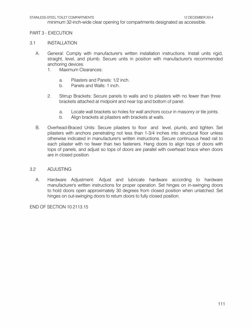
STAINLESS-STEEL TOILET COMPARTMENTS 12 DECEMBER 2014
minimum 32-inch-wide clear opening for compartments designated as accessible. PART 3 - EXECUTION
3.1 INSTALLATION
A. General: Comply with manufacturer's written installation instructions. Install units rigid,
straight, level, and plumb. Secure units in position with manufacturer's recommended anchoring devices. 1. Maximum Clearances:
a. Pilasters and Panels: 1/2 inch. b. Panels and Walls: 1 inch.
2. Stirrup Brackets: Secure panels to walls and to pilasters with no fewer than three
brackets attached at midpoint and near top and bottom of panel.
a. Locate wall brackets so holes for wall anchors occur in masonry or tile joints. b. Align brackets at pilasters with brackets at walls.
B. Overhead-Braced Units: Secure pilasters to floor and level, plumb, and tighten. Set
pilasters with anchors penetrating not less than 1-3/4 inches into structural floor unless otherwise indicated in manufacturer's written instructions. Secure continuous head rail to each pilaster with no fewer than two fasteners. Hang doors to align tops of doors with tops of panels, and adjust so tops of doors are parallel with overhead brace when doors are in closed position.
3.2 ADJUSTING
A. Hardware Adjustment: Adjust and lubricate hardware according to hardware
manufacturer's written instructions for proper operation. Set hinges on in-swinging doors to hold doors open approximately 30 degrees from closed position when unlatched. Set hinges on out-swinging doors to return doors to fully closed position.
END OF SECTION 10 2113.15
111

12 DECEMBER 2014
THIS PAGE INTENTIONALLY LEFT BLANK
112

TOILET, BATH, AND LAUNDRY ACCESSORIES 12 DECEMBER 2014
SECTION 10 2800 - TOILET, BATH, AND LAUNDRY ACCESSORIES
PART 1 - GENERAL
1.1 RELATED DOCUMENTS
A. Drawings and general provisions of the Contract, including General and Supplementary Conditions and Division 01 Specification Sections, apply to this Section.
1.2 COORDINATION
A. Coordinate accessory locations with other work to prevent interference with clearances
required for access by people with disabilities, and for proper installation, adjustment, operation, cleaning, and servicing of accessories.
1.3 ACTION SUBMITTALS
A. Product Data: For each type of product.
1. Include construction details, material descriptions, dimensions of individual
components and profiles, and finishes. 2. Include anchoring and mounting requirements, including requirements for cutouts
in other work and substrate preparation. PART 2 – PRODUCTS
2.1 PUBLIC-USE WASHROOM ACCESSORIES
A. Source Limitations: Obtain public-use washroom accessories from single source from single manufacturer.
B. Toilet Tissue (Roll) Dispenser:
1. Products: Subject to compliance with requirements, provide the following:
a. San Jamar “Versatwin” 2-roll tissue dispenser (Parks Dept. standard – no substitutions)
2. Description: Double-roll dispenser. 3. Mounting: Surface mounted, horizontal. 4. Operation: Spindle-less and self-locking device that prevents core removal until roll
is empty. 5. Capacity: Designed for two 5-1/2 inch diameter tissue rolls. 6. Material and Finish: ABS plastic, translucent cover. 7. Color: Black Pearl/White Sand (model R3600TBK)
C. Grab Bars:
1. Manufacturers: Subject to compliance with requirements, provide products by one of the following: a. American Specialties, Inc. b. Bobrick Washroom Equipment, Inc.
113

TOILET, BATH, AND LAUNDRY ACCESSORIES 12 DECEMBER 2014
c. Bradley Corporation.
2. Mounting: Flanges with exposed tamper-proof fasteners.
3. Material: Stainless steel, 0.05 inch thick. a. Finish: Smooth, No. 4 finish (satin).
4. Outside Diameter: 1-1/2 inches. 5. Configuration and Length: As indicated on Drawings.
D. Mirror Unit:
1. Manufacturers: Subject to compliance with requirements, provide products by one of the following: a. American Specialties, Inc. b. Bobrick Washroom Equipment, Inc. – Model B-1556 (basis of design) c. Bradley Corporation.
2. Frame: frameless with ¼” return
3. Mirror: 18-8 type 304 stainless steel polished to a No.8 mirror finish.
4. Backing: ¼” tempered masonite.
5. Hardware: 1/8” expansion bolts with tamper-proof heads, to fit countersunk mounting holes in mirror face.
6. Size: 18” x 30”.
E. Coat Hook: 1. Manufacturers: Subject to compliance with requirements, provide products by one
of the following: a. American Specialties, Inc. b. Bobrick Washroom Equipment, Inc. – Model B-233 (basis of design) c. Bradley Corporation.
2. Description: Single-prong unit. 3. Material and Finish: Stainless steel, No. 4 finish (satin). 4. Provide (1) hook at each toilet stall, mounted at the center of the door on the interior
side of the stall. a. At the accessible stalls, mount the hook at +46” above finish floor to the top
of the hook. b. At the standard stalls, mount the hook 6” below the top of the door (to the top
of the hook).
2.2 MATERIALS
A. Stainless Steel: ASTM A 666, Type 304, 0.031-inch minimum nominal thickness unless otherwise indicated.
B. Brass: ASTM B 19, flat products; ASTM B 16/B 16M, rods, shapes, forgings, and flat
products with finished edges; or ASTM B 30, castings.
C. Fasteners: Screws, bolts, and other devices of same material as accessory unit and
114

TOILET, BATH, AND LAUNDRY ACCESSORIES 12 DECEMBER 2014
tamper-and-theft resistant where exposed.
2.3 FABRICATION
A. General: Fabricate units with tight seams and joints, and exposed edges rolled. Hang doors and access panels with full-length, continuous hinges. Equip units for concealed anchorage and with corrosion-resistant backing plates.
PART 3 - EXECUTION 3.1 INSTALLATION
A. Install accessories according to manufacturers' written instructions, using fasteners
appropriate to substrate indicated and recommended by unit manufacturer. Install units level, plumb, and firmly anchored in locations and at heights indicated.
B. Grab Bars: Install to withstand a downward load of at least 250 lb-f, when tested according
to ASTM F 446. 3.2 ADJUSTING AND CLEANING
A. Adjust accessories for unencumbered, smooth operation. Replace damaged or defective
items.
B. Remove temporary labels and protective coatings.
C. Clean and polish exposed surfaces according to manufacturer's written instructions.
END OF SECTION 10 2800
115

COMMON WORK RESULTS FOR PLUMBING 12 DECEMBER 2014
SECTION 22 0500 - COMMON WORK RESULTS FOR PLUMBING
PART 1 - GENERAL
1.1 SECTION INCLUDES
A. Plumbing work includes the following: furnish and install all fixtures and piping
shown on the plumbing and architectural drawings described in these specifications. In connection with this work, contractor shall also furnish and install all necessary work, devices, hardware and systems required to make said systems properly and safely operable, including, but not limited to, support hardware, insulation, valves, flashing, cleanouts, cutting and patching.
1.2 WORK SEQUENCE
A. Install work in phases to accommodate County’s construction requirements. Refer to
Architectural and Plumbing Drawings for the construction details and coordinate the work of this division with that of other divisions. Order the work of this division so that progress will harmonize with that of other divisions and all work will proceed expeditiously.
1.3 SUBMITTALS
A. Submit on the following:
1. All fixtures, pipe, fittings, valves, insulation, hangers and supports, labels, fixtures, adhesives and sealants, and equipment that is planned to be installed on this project.
B. Proposed Products List: Include Products specified in the following Sections:
1. Division 22 - Plumbing. 2. Project Drawings.
C. Submit product data grouped to include complete submittals of related systems,
products, and accessories. Submittals shall clearly identify options provided, color, and model number.
D. Equipment and materials shall be ordered only after satisfactory review by County.
E. The following statement applies to all items reviewed: “Checking is only for general
conformance with the design concept of the project and general compliance with the information given in the contract documents. Any action shown is subject to the requirements of the plans and specifications. Contractor is responsible for dimensions which shall be confirmed at the job site; fabrication processes and techniques of construction; coordination of his work with that of other trades; and the satisfactory performance of his work.”
F. Maintain a complete set of the most current reviewed submittal and shop drawings
on site during construction.
116

COMMON WORK RESULTS FOR PLUMBING 12 DECEMBER 2014
1.4 REGULATORY REQUIREMENTS
A. Conform to 2013 California Building Code.
B. Fire Protection: Conform to 2013 California Fire Code, and California State Fire Marshall Regulations, Title 19, Public Safety.
C. Plumbing: Conform to 2013 California Plumbing Code.
D. Mechanical: Conform to 2013 California Mechanical Code.
E. Electrical: Conform to 2013 California Electrical Code.
F. Obtain approved inspections from authority having jurisdiction.
G. Conflicts: Where conflict or variation exists amongst Codes, the most stringent shall
govern.
1.5 PROJECT / SITE CONDITIONS
A. Install work in locations shown on drawings, unless prevented by project conditions.
B. Prepare drawings showing proposed rearrangement of work to meet project conditions, including changes to work specified in other Sections. Obtain permission of County before proceeding.
C. Piping Locations: Piping locations shown are diagrammatic only. Contractor
shall verify locations of all lateral stubs, offsets, etc. required in the field. The actual locations of lines, cleanouts and connections may vary provided that complete systems are installed in compliance with codes.
D. Construction Observation: In addition to the requirement for obtaining inspections by
the local jurisdiction, Contractor shall notify County representative at appropriate times during the construction process so that they can visit site to become generally familiar with the progress and quality of Contractor’s work and to determine if the work is proceeding in general accordance with the contract documents.
E. Scaling of Drawings: In no case shall working dimensions be scaled from plans, sections, or details from the working drawings. If no dimension is shown on the architectural drawings, the prime Contractor shall request in writing that the County provide clarification or the specific dimension.
1.6 QUALITY ASSURANCE
A. Qualification of Manufacturer: Products used in work shall be produced by
manufacturers regularly engaged in the manufacture of similar items.
B. Qualification of Installer: Use adequate number of skilled workmen, thoroughly trained and experienced in the necessary crafts, and completely familiar with the specified requirements contained in the plans and specifications.
117

COMMON WORK RESULTS FOR PLUMBING 12 DECEMBER 2014
C. Applicable equipment and materials to be listed by Underwriters’ Laboratories and
manufactured in accordance with ASME, AWWA, or ANSI standards. Power-using equipment shall meet the California energy efficiency standards as defined in the current Title 24 requirements.
D. Welding procedures and testing shall comply with ANSI Standard B31.1.0
standard code for pressure piping and the American Welding Society – Welding Handbook. Welding shall also comply with Division of the State Architect and structural plan requirements for materials, procedures, qualifications, and inspections.
1.7 DRAWINGS AND SPECIFICATIONS
A. Drawings and specifications are intended to complement each other. Where a conflict
exists between the requirements of the drawings and/or specifications, the contractor shall immediately and before commencing work, request clarification from County.
B. The County shall interpret the drawings and the specifications, and the County’s
decision as to the true intent and meaning thereof and the quality, quantity, and the sufficiency of the materials and workmanship furnished there under shall be accepted as final and conclusive.
C. Examine and compare the contract drawings and specifications with the drawings and
specifications of other trades. Report any discrepancies to the County. Install and coordinate the work in cooperation with the other trades.
1.8 DEFINITIONS
A. Finished Spaces: Spaces other than mechanical and electrical equipment rooms, furred spaces, pipe chases, unheated spaces immediately below roof, spaces above ceilings, unexcavated spaces, crawlspaces, and tunnels.
B. Exposed, Interior Installations: Exposed to view indoors. Examples include finished
occupied spaces and mechanical equipment rooms.
C. Exposed, Exterior Installations: Exposed to view outdoors or subject to outdoor ambient temperatures and weather conditions. Examples include rooftop locations.
D. Concealed, Interior Installations: Concealed from view and protected from physical
contact by building occupants. Examples include above ceilings and in chases.
E. Concealed, Exterior Installations: Concealed from view and protected from weather conditions and physical contact by building occupants but subject to outdoor ambient temperatures. Examples include installations within unheated shelters.
PART 2 - PRODUCTS
2.1 PRODUCTS
A. Maintain uniformity of manufacturer for equipment used in similar applications and
118

COMMON WORK RESULTS FOR PLUMBING 12 DECEMBER 2014
sizes.
B. Provide products and materials that are new, clean, and free from defects, damage, and corrosion.
C. Provide name/data plates on major components with manufacturer’s name, model
number, serial number, date of manufacturer, capacity data, and electrical characteristics permanently attached in a conspicuous location on the equipment.
D. Protect materials stored at site and installed from damage. Verify dimensions of
equipment and fixtures prior to ordering. PART 3 - EXECUTION
3.1 INSTALLATION
A. Install all equipment per the manufacturer’s instructions for installing, connecting, and
adjusting. A copy of the instructions shall be kept at the equipment during installation and provided to the County at his/her request.
B. Adjust pipes, ducts, panels, equipment, etc., to accommodate the work to prevent
interferences. 1. Right-of-Way: Lines which pitch have the right-of-way over those which do not
pitch. Lines whose elevations cannot change have right-of-way over lines whose elevations can be changed.
2. Provide offsets, transitions, and changes in directions of pipes as required to maintain proper head room and pitch on sloping lines. Provide traps, air vents, drains, etc., as required. It is the intent of this paragraph that all cost associated with compliance be borne by the contractor.
3. All equipment shall be firmly anchored to building structural elements. 4. Carefully check space requirements with other trades and existing conditions to
insure material, fixtures or equipment can be installed in the spaces allotted. 5. Damage / demolition repair: In the event that existing utilities of any type are
damaged by contractor, contractor shall immediately repair damage and restore services. If repairs are not able to be made immediately, contractor shall install temporary utilities as required to maintain utility services to all buildings and facilities. All concrete curb and gutter, flatwork, and landscaping removed or damaged by contractor shall be replaced in-kind by contractor. It is the intent of this section that the contractor be responsible for all costs associated with these notes.
END OF SECTION 22 0500
119

TRENCHING AND BACKFILLING FOR PIPED UTILITIES 12 DECEMBER 2014
SECTION 22 0505 - TRENCHING AND BACKFILLING FOR PIPED UTILITIES
PART 1 – GENERAL
1.1 SUMMARY
A. This Section includes the following:
1. Excavating and backfilling for utility trenches and pits for buried utility structures.
B. Related Sections include the following:
1. Division 22 Sections for installing underground utilities and buried structures.
1.2 DEFINITIONS
A. Backfill: Soil material or controlled low-strength material used to fill an excavation.
1. Initial Backfill: Backfill placed beside and over pipe in a trench, including haunches to support sides of pipe.
2. Final Backfill: Backfill placed over initial backfill to fill a trench.
B. Base Course: Course placed between the sub-base course and hot-mix asphalt paving.
C. Bedding Course: Course placed over the excavated subgrade in a trench before laying pipe.
D. Borrow Soil: Satisfactory soil imported from off-site for use as fill or backfill. E. Excavation: Removal of material encountered above subgrade elevations and to lines
and dimensions indicated. F. Fill: Soil materials used to raise existing grades. G. Structures: Buildings, footings, foundations, retaining walls, slabs, tanks, curbs,
mechanical and electrical appurtenances, or other man-made stationary features constructed above or below the ground surface.
H. Sub-base Course: Course placed between the subgrade and base course for hot-mix asphalt pavement, or course placed between the subgrade and a cement concrete pavement or a cement concrete or hot-mix asphalt walk.
I. Utilities: On-site underground pipes, conduits, ducts, and cables, as well as underground services within buildings.
1.3 SUBMITTALS
A. Product Data: For the following:
1. Each type of plastic warning tape.
120

TRENCHING AND BACKFILLING FOR PIPED UTILITIES 12 DECEMBER 2014
B. Material: Compliance with the following:
1. Classification according to ASTM D 2487 of each on-site and borrow soil material proposed for fill and backfill.
2. Compaction curve according to ASTM D 698 or ASTM D 1557 for each on-site and borrow soil material proposed for backfill.
1.4 PROJECT CONDITIONS
A. Existing Utilities: Provide a minimum of 48 hours advance notification of proposed utility interruption to facilities occupied by County. 1. Contact utility-locator service for area where Project is located before excavating.
B. Demolish and completely remove from site existing underground utilities indicated to
be removed. Coordinate with County to shut off or isolate services if lines are active. PART 2 - PRODUCTS
2.1 SOIL MATERIALS
A. General: Provide borrow soil materials when sufficient satisfactory soil materials are
not available from excavations. B. Satisfactory Soils: As approved by County. C. Bedding Course: Naturally or artificially graded mixture of natural or crushed gravel,
crushed stone, and natural or crushed sand; ASTM D 2940; except with 100 percent passing a 1-inch (25-mm) sieve and not more than 8 percent passing a No. 200 (0.075-mm) sieve.
D. Filter Material: Narrowly graded mixture of natural or crushed gravel, or crushed stone and natural sand; ASTM D 448; coarse-aggregate grading Size 67; with 100 percent passing a 1-inch (25-mm) sieve and 0 to 5 percent passing a No. 4 (4.75-mm) sieve.
E. Sand: ASTM C 33; fine aggregate, natural, or manufactured sand.
2.2 ACCESSORIES
A. Detectable Warning Tape: Acid- and alkali-resistant polyethylene film warning tape manufactured for marking and identifying underground utilities, a minimum of 6 inches (150 mm) wide and 4 mils (0.1 mm) thick, continuously inscribed with a description of the utility, with metallic core encased in a protective jacket for corrosion protection, detectable by metal detector when tape is buried up to 30 inches (750 mm) deep; colored as follows:
1. Red: Electric. 2. Yellow: Gas, oil, steam, and dangerous materials. 3. Orange: Telephone and other communications. 4. Blue: Water systems.
121

TRENCHING AND BACKFILLING FOR PIPED UTILITIES 12 DECEMBER 2014
5. Green: Sewer systems.
PART 3 – EXECUTION
3.1 PREPARATION
A. Protect structures, utilities, sidewalks, pavements, and other facilities from damage caused by settlement, lateral movement, undermining, washout, and other hazards created by earthwork operations.
B. Prepare subgrade for earthwork operations including removal of vegetation, topsoil, debris, obstructions, and deleterious materials from ground surface.
C. Protect and maintain erosion and sedimentation controls.
3.2 DEWATERING
A. Prevent surface water and ground water from entering excavations, from ponding on prepared subgrades, and from flooding Project site and surrounding area.
B. Protect subgrades from softening, undermining, washout, and damage by rain or water accumulation.
1. Reroute surface water runoff away from excavated areas. Do not allow water to
accumulate in excavations.
3.3 EXCAVATION FOR UTILITY TRENCHES
A. Underground alert: Before laying out piping and performing trenching, contactor shall determine locations of existing underground utilities. Contact "Dig Alert / Underground Service Alert of Southern California" - 1-800-422-4133. Contractor shall also coordinate with County to ascertain locations of underground piping and other conditions affecting trenching.
B. Trenching: Material shall be excavated from trenches and piled adjacent to the trench. Material shall be piled in such a manner that will cause a minimum of inconvenience to public travel. All rock, boulders, and stones shall be removed to provide a minimum clearance of six (6) inches under and around pipes. Excavations shall be kept free of water. Trenches shall be dug to true and smooth bottom grades and in accordance with the lines indicated on drawings and as directed. Trench widths shall not exceed 30 inches or 1.5 times outside diameter of the pipe plus 18 inches, whichever is greater. Minimum trench width shall be the outside diameter of pipe installed plus 12 inches. Depth of trenching for water piping shall provide a minimum cover of 18 inches over the top of the pipe.
C. Sewers and Drains: shall be of sufficient width to permit proper jointing of the pipe and back filling of material along the sides of the pipe. Trenches shall be excavated below the barrel of the pipe a sufficient distance to provide for bedding material where the trench bottom consists of a material which is unsuitable for foundation or which will make it difficult to obtain uniform bearing for the pipe. Such material shall be removed
122

TRENCHING AND BACKFILLING FOR PIPED UTILITIES 12 DECEMBER 2014
and a stable foundation provided. This shall include the preparation of the native trench bottom and/or the top of the foundation material to a uniform grade so that the entire length of pipe rests firmly on a suitable properly compacted sand or gravel material per Section 22 0505 2.1
1. For pipes and conduit less than 6 inches (150 mm) in nominal diameter and flat-
bottomed, multiple-duct conduit units, hand-excavate trench bottoms and support pipe and conduit on an undisturbed subgrade with bedding course.
2. For pipes and conduit 6 inches (150 mm) or larger in nominal diameter, shape bottom of trench to support bottom 90 degrees of pipe circumference. Fill depressions with tamped sand backfill.
D. Trench Bottoms: Excavate trenches 4 inches (100 mm) deeper than bottom of pipe
elevation to allow for bedding course. Hand excavate for bell of pipe.
1. Excavate trenches 6 inches (150 mm) deeper than elevation required in rock or other unyielding bearing material to allow for bedding course.
3.4 UTILITY TRENCH BACKFILL
A. Backfill: Contactor shall complete bedding and then backfill to 6 inches over the top of the pipe with sand before starting backfilling operations. Take all precautions necessary to protect the pipe from damage, movement and shifting. Compaction equipment used above the pipe zone shall be of a type that does not injure the pipe. Where original excavated material is unsuitable for trench backfill, backfill gravel shall be placed.
B. Unsuitable material shall be removed to the disposal area.
C. Warning tape markers and tracer wires shall be installed during backfill operations.
D. Existing roadway, restoration and compaction shall be achieved as the trench is backfilled so as to maintain traffic. Provide temporary, traffic-bearing steel plates over excavations in public rights-of-way, if backfilling and re-paving cannot be accomplished before end of work period. Trench backfill under roadway shall be mechanically compacted to 95 percent of maximum density except for trenches over 8 feet in depth. In any trench in which 95 percent density cannot be achieved with existing backfill, the top 4 feet shall be replaced with backfill gravel mechanically compacted to 95 percent.
E. Contractor shall be responsible to provide the proper size and type of compaction
equipment and select the proper method of utilizing said equipment to attain the required compaction density. Compaction by water jetting will not be permitted.
F. Where backfill is required to be certified, compliance shall be performed in
accordance with the requirements of the governing authority. Allow inspector to approve each subgrade and fill layer before further fill, backfill or construction work is performed.
G. Protecting Graded Areas: Protect newly graded areas from traffic, freezing, and
123

TRENCHING AND BACKFILLING FOR PIPED UTILITIES 12 DECEMBER 2014
erosion. Keep free of trash and debris.
H. Repair and reestablish grades to specified tolerances where completed or partially completed surfaces become eroded, rutted, settled, or where they lose compaction due to subsequent construction operations or weather conditions.
1. Scarify or remove and replace soil material to depth as directed by County;
reshape and recompact.
I. Where settling occurs before Project correction period elapses, remove finished surfacing, backfill with additional soil material, compact, and reconstruct surfacing.
1. Restore appearance, quality, and condition of finished surfacing to match
adjacent work, and eliminate evidence of restoration to greatest extent possible. END OF SECTION 22 0505
124

PLUMBING PIPING 12 DECEMBER 2014
SECTION 22 0510 - PLUMBING PIPING
PART 1 - GENERAL
1.1 RELATED DOCUMENTS
A. Drawings, notes, and general provisions of the Contract, including General and
Supplemental Conditions and Division 01 specification sections, apply to this section.
1.2 SUMMARY
A. Section Includes:
1. Pipe and fittings for domestic water, and waste and vent. 2. Escutcheons. 3. Cleanouts. 4. Vandal-Proof Vent Caps. 5. Supply tubes & Angle Stops.
1.3 REFERENCES
A. ANSI B31.9 - Building Service Piping.
B. ASME B16.3 - Malleable Iron Threaded Fittings.
C. ASME B16.22 - Wrought Copper and Bronze Solder-Joint Pressure Fittings.
D. ASTM A47 - Ferritic Malleable Iron Castings.
E. ASTM A53 - Pipe, Steel, Black and Hot-Dipped Zinc Coated, Welded and Seamless.
F. ASTM A74 - Cast Iron Soil Pipe and Fittings.
G. ASTM A120 - Pipe, Steel, Black and Hot-Dipped Zinc Coated (Galvanized), Welded
and Seamless, for Ordinary Uses.
H. ASTM B32 - Solder Metal.
I. ASTM B88 - Seamless Copper Water Tube.
J. ASTM C564 - Rubber Gaskets for Cast Iron Soil Pipe and Fittings.
K. ASTM D1785 - Poly Vinyl Chloride (PVC) Plastic Pipe, Schedules 40, 80, and 120.
L. ASTM D2241 - Poly Vinyl Chloride (PVC) Plastic Pipe (SDR-PR).
M. ASTM D2466 - Poly Vinyl Chloride (PVC) Plastic Pipe Fittings, Schedule 40.
N. ASTM D2564 - Solvent Cements for Poly Vinyl Chloride (PVC) Plastic Pipe and Fittings.
125

PLUMBING PIPING 12 DECEMBER 2014
O. ASTM D2855 - Making Solvent-Cemented Joints with Poly Vinyl Chloride (PVC) Pipe
and Fittings.
P. ASTM D3034 - Poly Vinyl Chloride (PVC) Plastic Sewer Pipe SDR-35.
Q. CISPI 301 - Cast Iron Soil Pipe and Fittings for Hubless Cast Iron Sanitary Systems.
R. CISPI 310 - Joints for Hubless Cast Iron Sanitary Systems.
S. ASTM D2513 - SDR11.5 Polyethylene Gas Pipe.
T. ASTM D1784 – Low Extractable Polyvinyl Chloride for filtered water. 1.4 SUBMITTALS
A. Product Data: For the following products:
1. Piping, fittings and escutcheons.
B. Project Record Documents
1. Submit drawings recording actual locations of valves and piping.
C. Operation and Maintenance Data
1. Submit Maintenance Data: Include installation instructions, spare parts lists,
exploded assembly views. 1.5 REGULATORY REQUIREMENTS
A. Perform Work in accordance with 2013 California plumbing code.
1.6 DELIVERY, STORAGE, AND HANDLING
A. Provide temporary protective coating on cast iron and steel valves.
B. Protect piping systems from entry of foreign materials by temporary covers,
completing sections of the work, and isolating parts of completed system.
PART 2 - PRODUCTS
2.1 DOMESTIC WATER PIPING, ABOVE GROUND
A. Hard Copper Tube: ASTM B88, type L water tube, drawn temper. U.S. Manufactured.
1. Wrought-copper solder-joint fittings: ASME B16.22, wrought-copper pressure fittings, with lead-free solder.
2. Bronze Flanges: ASME B16.24, class 150, with solder-joint ends. 126

PLUMBING PIPING 12 DECEMBER 2014
3. Copper Unions: MSS SP-123, cast-copper-alloy, hexagonal-stock body, with ball-and-socket, metal-to-metal seating surfaces, solder-joint or threaded ends.
4. All copper and fittings shall be made in the United States.
2.2 DOMESTIC WATER PIPING, BELOW GRADE
A. Soft Copper Tube: ASTM B88, Type K water tube, annealed temper. U.S. Manufactured.
1. Copper solder-joint fitting: ASME B16.22, wrought-copper pressure fittings. No
joints under slabs. 2. Non lead bearing solder. 3. Copper shall be sleeved with polyethylene. 4. Joints between site PVC and underground copper shall be made with male
PVC/female copper adapters. 5. All copper and fittings shall be made in the United States.
2.3 DOMESTIC SITE WATER PIPING, BELOW GRADE (Greater than 80 PSI)
A. Schedule 80 PVC, ASTM D1785. U.S. Manufactured.
1. Fittings – ASTM D2466. 2. Solvent – cement joints, ASTM D2564/D2855. 3. Joints between site PVC and underground copper shall be made with male
PVC/female copper adapters. 4. Install an unbroken number 18 tracer wire shall be installed with and attached to
underground non-metallic pipe and shall terminate above grade at each end. 5. Install polyethylene plastic utility warning tape above buried piping.
2.4 SANITARY WASTE AND VENT PIPING
A. Within the building and out 5 feet
1. Hubless cast-iron pipe and fittings: ASTM A888 or CISPI 301 of US manufacture. 2. Standard shielded couplings, stainless steel: CISPI 310, NSF-certified. 3. Heavy-duty couplings, stainless steel: ASTM C564. Use four-band clamps at
sanitary waste piping greater than 2”. 4. All cast-iron pipe and fittings and couplings shall be manufactured in the U.S. 5. Minimum slope ¼” per foot to drain with no bellies in piping. 6. Wrap buried cast-iron piping with 10 mil plastic and secure with tape
B. Underground past 5 feet from building
1. PVC SDR 35 with waste fittings. 2. Minimum slope ¼” per foot to drain with no bellies in piping. 3. All PVC waste piping shall be manufactured in the United States
127

PLUMBING PIPING 12 DECEMBER 2014
2.5 ESCUTCHEONS
A. Escutcheons for gas and water piping penetrations.
1. Manufacturers: subject to compliance with requirements, provide products by
the following: a. Brasscraft or equal
2. Description: chrome-plated cast brass with set screws.
2.6 CLEANOUTS
A. Cleanouts for waste piping.
1. Manufacturers: subject to compliance with requirements, provide products by
one of the following: a. J.R. Smith b. Zurn.
2. Description: cast-iron with threaded bronze plug. 18 gage stainless cover with
vandal-proof screws for wall cleanout. Polished brass non-slip cover for floor cleanout. Concrete box for cleanout to grade.
2.7 VANDAL-PROOF VENT CAPS
A. Vandal-proof vent caps
1. Manufacturers: subject to compliance with requirements, provide products by
one of the following: a. J.R. Smith b. Zurn.
2. Description: cast-iron dome secured with recessed Allen Key Set screws. 2.8 SUPPLY TUBES & ANGLE STOPS
A. Supply tubes:
1. Manufacturers: subject to compliance with requirements, provide products by: a. Brasscraft Speedi Plumb Plus.
2. Description: braided stainless steel with PVC inner hose, ½” Comp. x ½” FIP. 3. IAMPO Listed
B. Angle Stops:
1. Manufacturers: subject to compliance with requirements, provide products by the following: a. Brass Chrome Plated Loose Key Heavy Pattern lead-free ½” FIP inlet and
½” Comp. outlet.
1). Brasscraft.
128

PLUMBING PIPING 12 DECEMBER 2014
2). Kohler PART 3 - EXECUTION
3.1 EXAMINATION
A. Verify that excavations are to required grade, dry, and not over-excavated.
3.2 PREPARATION
A. Ream pipe and tube ends. Remove burrs.
B. Remove scale and dirt, on inside and outside, before assembly.
C. Prepare piping connections to equipment with flanges or unions.
3.3 INSTALLATION
A. Install in accordance with Manufacturer's instructions.
B. Provide non-conducting dielectric connections wherever jointing dissimilar metals.
C. Route piping in orderly manner and maintain gradient.
D. Install piping to allow for expansion and contraction without stressing pipe, joints, or connected equipment.
E. Provide clearance for installation of insulation and access to valves and fittings.
F. Provide access where valves and fittings are not exposed. Coordinate size and
location of access doors.
G. Where pipe support members are welded to structural building framing, scrape, brush clean, and apply one coat of zinc rich primer to welding.
H. Provide support for utility meters in accordance with requirements of utility
companies. I. Prepare pipe, fittings, supports, and accessories not pre-finished, ready for finish
painting. J. Seal all penetrations through exterior walls and fire rated walls with 3M Firestopping
materials for fire rating capacity per the architectural plans and UBC requirements.
K. Underground Alert: Before laying out piping and performing trenching, contractor shall determine locations of existing underground utilities. Contact "Dig Alert / Underground Service Alert of Southern California" 1-800-422-4133. Contractor shall also contact County's representative to ascertain locations of underground piping and other conditions affecting trenching. Do not perform trenching until all utilities have been located and marked.
L. Test all piping per 2013 California Plumbing Code Requirements and district
standards. 129

PLUMBING PIPING 12 DECEMBER 2014
3.4 APPLICATION
A. Install unions downstream of valves and at equipment or apparatus connections.
B. Install brass male adapters each side of valves in copper piped system. Sweat solder
adapters to pipe.
C. Install gate valves for shut-off and to isolate equipment, part of systems, or vertical risers.
3.5 ERECTION TOLERANCES
A. Slope water piping and arrange to drain at low points.
END OF SECTION 22 0510
130

GENERAL-DUTY VALVES FOR PLUMBING PIPING 12 DECEMBER 2014
SECTION 22 0523 - GENERAL-DUTY VALVES FOR PLUMBING PIPING
PART 1 - GENERAL
1.1 RELATED DOCUMENTS
A. Drawings and general provisions of the Contract, including General and
Supplementary Conditions and Division 01 Specification Sections, apply to this Section.
1.2 SUMMARY
A. Section Includes:
1. Bronze ball valves. 2. Bronze gate valve. 3. PVC ball valves. 4. Hydrants.
B. Related Sections:
1. Division 22 plumbing piping Sections for specialty valves applicable to those
Sections only. 2. Division 22 Section "Identification for Plumbing Piping and Equipment" for valve
tags and schedules. 3. Division 22 Section “Supports and Anchors for Plumbing Pipes and Equipment”
for pipe and valve anchorage to wall.
1.3 SUBMITTALS
A. Product Data: For each type of valve indicated.
1.4 QUALITY ASSURANCE
A. Source Limitations for Valves: Obtain each type of valve from single source from single manufacturer.
B. ASME Compliance:
1. ASME B16.10 and ASME B16.34 for ferrous valve dimensions and design criteria.
2. ASME B31.1 for power piping valves. 3. ASME B31.9 for building services piping valves.
C. NSF Compliance: NSF 61 for valve materials for potable-water service.
1.5 STORAGE, AND HANDLING
A. Use the following precautions during storage:
131

GENERAL-DUTY VALVES FOR PLUMBING PIPING 12 DECEMBER 2014
1. Maintain valve end protection. 2. Store valves indoors. If outdoor storage is necessary, store valves off the
ground in watertight enclosures. PART 2 - PRODUCTS
2.1 GENERAL REQUIREMENTS FOR VALVES
A. Refer to valve schedule articles for applications of valves. B. Valve Pressure and Temperature Ratings: Not less than indicated and as required for
system pressures and temperatures. C. Valve Sizes: Same as upstream piping unless otherwise indicated. D. Valves in Insulated Piping: With 2-inch (50-mm) stem extensions and the following
features: 1. Ball Valves: With extended operating handle of non-thermal-conductive
material, and protective sleeve that allows operation of valve without breaking the vapor seal or disturbing insulation.
E. Valve-End Connections:
1. Flanged: With flanges according to ASME B16.1 for iron valves. 2. Grooved: With grooves according to AWWA C606. 3. Solder Joint: With sockets according to ASME B16.18. 4. Threaded: With threads according to ASME B1.20.1.
F. Lead Content: Comply with State of California laws SB1334.
2.2 BRONZE BALL VALVES
A. Two-Piece, Full-Port, Bronze Ball Valves with Bronze Trim: 1. Manufacturers: Provide products by one of the following:
a. Conbraco Industries, Inc.; Apollo Valves. b. NIBCO INC. S-685-80-LF to 2”; NIBCO T-FP-600A-LF › 2”.
2.3 GATE VALVES
A. Lead-Free, Bronze Gate Valves: 1. Manufacturers: Provide the following:
a. NIBCO INC. T-113-LF 2.4 PVC Ball Valves
A. PVC & CPVC True Union Ball Valve: 1. Manufacturer: Provide products by the following:
a. Spears. 2.5 HYDRANTS
A. Hydrants, Lead Free. 1. Manufacturer: subject to compliance with requirements, provide products by the
following:
a. Woodford.
132

GENERAL-DUTY VALVES FOR PLUMBING PIPING 12 DECEMBER 2014
b. Zurn 2.6 EXAMINATION
A. Examine valve interior for cleanliness, freedom from foreign matter, and corrosion.
Remove special packing materials, such as blocks, used to prevent disc movement during shipping and handling.
B. Operate valves in positions from fully open to fully closed. Examine guides and seats made accessible by such operations.
C. Examine threads on valve and mating pipe for form and cleanliness. D. Examine mating flange faces for conditions that might cause leakage. Check bolting
for proper size, length, and material. Verify that gasket is of proper size, that its material composition is suitable for service, and that it is free from defects and damage.
E. Do not attempt to repair defective valves; replace with new valves. 2.7 VALVE INSTALLATION
A. Install valves with unions or flanges at each piece of equipment arranged to allow
service, maintenance, and equipment removal without system shutdown. B. Locate valves for easy access and provide separate support where necessary. C. Install valves in horizontal piping with stem at or above center of pipe. D. Install valves in position to allow full stem movement.
2.8 ADJUSTING
A. Adjust or replace valve packing after piping systems have been tested and put into
service but before final adjusting and balancing. Replace valves if persistent leaking occurs.
2.9 GENERAL REQUIREMENTS FOR VALVE APPLICATIONS
A. If valve applications are not indicated, use the following:
1. Domestic Water Shutoff Service: Gate valves (Nibco T-113-LF). 2. Throttling Service: Globe valves.
B. If valves with specified SWP classes or CWP ratings are not available, the same types
of valves with higher SWP classes or CWP ratings may be substituted. C. Select valves, except wafer types, with the following end connections:
1. For Copper Tubing, 2”and Smaller: Soldered ends. 2. For Copper Tubing, 2-1/2” to NPS 4”. Flanged. 3. For Steel Piping, 1-1/2” and Smaller: Threaded ends. 4. For Steel Piping, 2” TO 4”. Flanged.
END OF SECTION 22 0523
133

IDENTIFICATION FOR PLUMBING PIPING AND EQUIPMENT 12 DECEMBER 2014
SECTION 22 0553 - IDENTIFICATION FOR PLUMBING PIPING AND EQUIPMENT PART 1 - GENERAL
1.1 RELATED DOCUMENTS
A. Drawings and general provisions of the Contract, including General and
Supplementary Conditions and Specification Sections, apply to this Section.
1.2 SUMMARY A. Section Includes:
1. Valve tags. 2. Warning tags.
1.3 SUBMITTALS
A. Product Data: For each type of product indicated. B. Valve numbering scheme. C. Valve Schedules: For each piping system to include in maintenance manuals.
PART 2 – PRODUCT 2.1 VALVE TAGS
A. Valve Tags: Stamped or engraved with 1/4-inch letters for piping system abbreviation
and 1/2-inch numbers.
1. Tag Material: Brass, 0.032-inch minimum thickness, and having predrilled or stamped holes for attachment hardware.
2. Fasteners: Brass wire-link or beaded chain; or S-hook.
B. Valve Schedules: For each piping system, on 8-1/2-by-11-inch bond paper. Tabulate valve number, piping system, system abbreviation (as shown on valve tag), location of valve (room or space), normal-operating position (open, closed, or modulating), and variations for identification. Mark valves for emergency shutoff and similar special uses.
1. Valve-tag schedule shall be included in operation and maintenance data.
2.2 WARNING TAGS
A. Warning Tags: Preprinted or partially preprinted, accident-prevention tags, of
plasticized card stock with matte finish suitable for writing.
1. Size: 3 by 5-1/4 inches minimum. 2. Fasteners: Brass grommet and wire. 3. Nomenclature: Large-size primary caption such as "DANGER," "CAUTION,"
or "DO NOT OPERATE." 4. Color: Yellow background with black lettering.
134
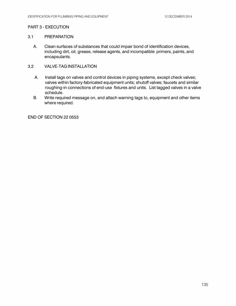
IDENTIFICATION FOR PLUMBING PIPING AND EQUIPMENT 12 DECEMBER 2014
PART 3 - EXECUTION
3.1 PREPARATION
A. Clean surfaces of substances that could impair bond of identification devices,
including dirt, oil, grease, release agents, and incompatible primers, paints, and encapsulants.
3.2 VALVE-TAG INSTALLATION
A. Install tags on valves and control devices in piping systems, except check valves; valves within factory-fabricated equipment units; shutoff valves; faucets and similar roughing-in connections of end-use fixtures and units. List tagged valves in a valve schedule.
B. Write required message on, and attach warning tags to, equipment and other items where required.
END OF SECTION 22 0553
135
SUPPORTS AND ANCHORS FOR PLUMBING PIPES AND EQUIPMENT 12 DECEMBER 2014
SECTION 22 1000 - SUPPORTS AND ANCHORS FOR PLUMBING PIPES AND EQUIPMENT
PART 1 - GENERAL
1.1 SECTION INCLUDES
A. Pipe and equipment hangers and supports. B. Equipment bases and supports. C. Sleeves and seals. D. Flashing and sealing equipment and pipe stacks.
1.2 REFERENCES
A. ASME B31.9 - Building Services Piping. B. ASTM F708 - Design and Installation of Rigid Pipe Hangers. C. MSS SP58 - Pipe Hangers and Supports - Materials, Design and Manufacturers. D. MSS SP69 - Pipe Hangers and Supports - Selection and Application. E. MSS SP89 - Pipe Hangers and Supports - Fabrication and Installation Practices.
1.3 SUBMITTALS
A. Product Data: Provide Manufacturers catalog data including load capacity.
1.4 REGULATORY REQUIREMENTS
A. Conform to 2013 California Plumbing Code Chapter 3 for support of piping. B. Brace piping & ducts to resist seismic induced motion per 2008 SMACNA Seismic
Restraint Guidelines. Hazard level is A. PART 2 - PRODUCTS
2.1 PIPE HANGERS AND SUPPORTS
A. Manufacturers:
1. Unistrut 2. B-Line 3. Michigan Hanger
B. Plumbing Piping - Domestic Water:
1. Conform to ASTM F708. 2. Hangers for Pipe Sizes 1/2 to 1-1/2 Inch (13 to 38 mm): Carbon steel, adjustable
swivel, split ring, copper plated for copper pipes. 3. Hangers for Cold Pipe Sizes 2 Inches (50 mm) and Over: Carbon steel, adjustable,
clevis. 4. Multiple or Trapeze Hangers: Steel channels with welded spacers and hanger rods. 5. Wall Support for Pipe Sizes to 3 Inches (76 mm): Cast iron hook. 6. Vertical Support: Steel riser clamp. 7. Floor Support for Cold Pipe: Cast iron adjustable pipe saddle, lock nut, nipple, floor
flange, and concrete pier or steel support.
136

SUPPORTS AND ANCHORS FOR PLUMBING PIPES AND EQUIPMENT 12 DECEMBER 2014
8. Copper Pipe Support: Carbon steel ring, adjustable, copper plated. 9. Rooftop Support – Miro Blocks 10. Copper clamps for water piping.
2.2 ACCESSORIES
A. Hanger Rods: Mild steel threaded both ends, threaded one end, or continuous
threaded. 2.3 FLASHING
A. Provide flashings for all pipe roof penetrations.
PART 3 - EXECUTION
3.1 INSTALLATION
A. Install in accordance with Manufacturer’s instructions. B. All ducting, piping, and equipment shall be installed to resist seismic motion and shall
comply with the requirements of the 2008 edition of the SMACNA Seismic Restraint Manual for seismic level “A”.
3.2 PIPE HANGERS AND SUPPORTS
A. Support horizontal piping as scheduled. B. Install hangers to provide minimum 1/2 inch (13 mm) space between finished covering
and adjacent work. C. Place hangers within 12 inches (300 mm) of each horizontal elbow. D. Support horizontal cast iron pipe adjacent to each hub, with 5 feet (1.5 m) maximum
spacing between hangers. E. Support vertical piping at every floor. Support vertical cast iron pipe at each floor at hub. F. Where several pipes can be installed in parallel and at same elevation, provide multiple
or trapeze hangers. G. Support riser piping independently of connected horizontal piping. H. Provide copper plated hangers and supports for copper piping. I. Design hangers for pipe movement without disengagement of supported pipe. J. Prime coat exposed steel hangers and supports. Refer to Division 9 – Painting. Hangers
and supports located in crawl spaces and pipe shafts are not considered exposed. K. Install plastic pipe isolators for copper piping at all wood penetrations.
3.3 EQUIPMENT BASES AND SUPPORTS
A. Provide templates, anchor bolts, and accessories for mounting and anchoring
equipment. 3.4 FLASHING
A. Provide flexible flashing and metal counterflashing where piping and ductwork penetrate
weather or waterproofed walls, floors, and roofs.
137

SUPPORTS AND ANCHORS FOR PLUMBING PIPES AND EQUIPMENT 12 DECEMBER 2014
3.5 SCHEDULES
MAXIMUM
HANGER ROD
PIPE SIZE Inches (mm) 1/2 to 1-1/4 (12 to 32)
HANGER SPACING Feet (m) 6.5 (2)
DIAMETER Inches (mm)
3/8 (9)
1-1/2 to 2 (38 to 50)
10 (3) 3/8 (9)
2-1/2 to 3 (62 to 75)
10 (3) 1/2 (13)
END OF SECTION 22 1000
138

PLUMBING FIXTURES AND EQUIPMENT 12 DECEMBER 2014
SECTION 22 4000 - PLUMBING FIXTURES AND EQUIPMENT
PART 1 - GENERAL
1.1 RELATED DOCUMENTS
A. Drawings and general provisions of the Contract, including General and
Supplementary Conditions and these Specifications.
1.2 SUMMARY
A. This Section includes the following plumbing fixtures, equipment, and related components:
1. Faucets for Lavatories. 2. Flushometers. 3. Fixture Supports. 4. Water Closets. 5. Urinals. 6. Lavatories. 7. Hydrants. 8. Floor Drains. 9. Trap Primers. 10. Water Hammer Arrestors. 11. Drinking Fountains.
1.3 DEFINITIONS
A. ABS: Acrylonitrile-butadiene-styrene plastic. B. Accessible Fixture: Plumbing fixture that can be approached, entered, and used by
people with disabilities. C. Cast Polymer: Cast-filled-polymer-plastic material. This material includes cultured-
marble and solid-surface materials. D. Cultured Marble: Cast-filled-polymer-plastic material with surface coating. E. Fitting: Device that controls the flow of water into or out of the plumbing fixture.
Fittings specified in this Section include supplies and stops, faucets and spouts, shower heads and tub spouts, drains and tailpieces, and traps and waste pipes. Piping and general-duty valves are included where indicated.
F. FRP: Fiberglass-reinforced plastic. G. PMMA: Polymethyl methacrylate (acrylic) plastic. H. PVC: Polyvinyl chloride plastic. I. Solid Surface: Nonporous, homogeneous, cast-polymer-plastic material with heat-,
impact-, scratch-, and stain-resistance qualities.
1.4 SUBMITTALS
A. Product Data: For each type of plumbing fixture indicated. Include selected fixture and trim, fittings, accessories, appliances, appurtenances, equipment, and supports. Indicate materials and finishes, dimensions, construction details, and flow-control rates.
139

PLUMBING FIXTURES AND EQUIPMENT 12 DECEMBER 2014
B. Environmental Submittals: Product data for adhesives and sealants used inside of the
weatherproofing system, including printed statement of VOC content. C. Operation and Maintenance Data: For plumbing fixtures to include in emergency,
operation, and maintenance manuals. D. Warranty: Special warranty specified in this Section.
1.5 QUALITY ASSURANCE
A. Accessible Plumbing Fixture Regulatory Requirements: Accessible plumbing fixtures
shall comply with all of the requirements of CBC Section 1115B. Height and locations of all fixtures shall be according to CBC Table 1115B-1. Fixture controls shall comply with CBC Section 1118B.
B. Source Limitations: Obtain plumbing fixtures, faucets, and other components of each category through one source from a single manufacturer.
1. Exception: If fixtures, faucets, or other components are not available from a
single manufacturer, obtain similar products from other manufacturers specified for that category.
C. Electrical Components, Devices, and Accessories: Listed and labeled as defined in
2010 CEC, by a testing agency acceptable to authorities having jurisdiction, and marked for intended use.
D. Regulatory Requirements: Comply with requirements in ICC A117.1, "Accessible and Usable Buildings and Facilities" "Americans with Disabilities Act"; for plumbing fixtures for people with disabilities.
E. Regulatory Requirements: Comply with requirements in Public Law 102-486, "Energy Policy Act," about water flow and consumption rates for plumbing fixtures.
F. NSF Standard: Comply with NSF 61, "Drinking Water System Components--Health Effects," for fixture materials that will be in contact with potable water.
G. Select combinations of fixtures and trim, faucets, fittings, and other components that are compatible.
H. Comply with the following applicable standards and other requirements specified for plumbing fixtures:
1. Enameled, Cast-Iron Fixtures: ASME A112.19.1M. 2. Vitreous-China Fixtures: ASME A112.19.2M. 3. Water-Closet, Flushometer Tank Trim: ASSE 1037.
I. Comply with the following applicable standards and other requirements specified for
lavatory and sink faucets:
1. Faucets: ASME A112.18.1. 2. Integral, Atmospheric Vacuum Breakers: ASSE 1001. 3. NSF Potable-Water Materials: NSF 61. 4. Pipe Threads: ASME B1.20.1. 5. Sensor-Actuated Faucets and Electrical Devices: UL 1951. 6. Supply Fittings: ASME A112.18.1. 7. Brass Waste Fittings: ASME A112.18.2. 8. Lead-free construction.
140

PLUMBING FIXTURES AND EQUIPMENT 12 DECEMBER 2014
J. Comply with the following applicable standards and other requirements specified for
miscellaneous fittings:
1. Brass Waste Fittings: ASME A112.18.2. 2. Sensor-Operation Flushometers: ASSE 1037 and UL 1951. 3. Lead-free construction.
K. Comply with the following applicable standards and other requirements specified for
miscellaneous components:
1. Flexible Water Connectors: ASME A112.18.6. 2. Floor Drains: ASME A112.6.3. 3. Hose-Coupling Threads: ASME B1.20.7. 4. Hot-Water Dispensers: ASSE 1023 and UL 499. 5. Off-Floor Fixture Supports: ASME A112.6.1M. 6. Pipe Threads: ASME B1.20.1. 7. Plastic Toilet Seats: ANSI Z124.5. 8. Supply and Drain Protective Shielding Guards: ICC A117.1. 9. Lead-free construction.
1.6 EXTRA MATERIALS
A. Furnish extra materials described below that match products installed and that are
packaged with protective covering for storage and identified with labels describing contents.
1. Faucet Cartridges and O-Rings: Provide two repair kits for each type faucet.
PART 2 - PRODUCTS
2.1 LAVATORY FAUCETS
A. Lavatory Faucets: 1. Manufacturers: Subject to compliance with requirements, provide products by
one the following: a. See Plumbing Schedule.
2.2 FLUSHOMETERS
A. Flushometers:
1. Manufacturers: Subject to compliance with requirements, provide products by the following: a. See Plumbing Schedule.
2.3 FIXTURE SUPPORTS
A. Manufacturers: Subject to compliance with requirements, provide products by one of
the following:
1. Smith, Jay R. Mfg. Co. 2. Zurn Plumbing Products Group; Specification Drainage Operation.
141

PLUMBING FIXTURES AND EQUIPMENT 12 DECEMBER 2014
B. Water-Closet Supports:
1. Description: Combination carrier designed for accessible or standard mounting height of wall-mounting, water-closet-type fixture. Include single or double, vertical or horizontal, hub-and-spigot or hubless waste fitting as required for piping arrangement; faceplates; couplings with gaskets; feet; and fixture bolts and hardware matching fixture. Include additional extension coupling, faceplate, and feet for installation in wide pipe space. Verify width of wall and submit support that fits in wall width.
C. Urinal Supports:
1. Description: Type I, urinal carrier with fixture support plates and coupling
with seal and fixture bolts and hardware matching fixture for wall-mounting, urinal- type fixture. Include steel uprights with feet.
2. Accessible-Fixture Support: Include rectangular steel uprights.
2.4 WATER CLOSETS
A. Water Closets: 1. Manufacturers: Subject to compliance with requirements, provide products by
the following: a. See Plumbing Schedule.
2.5 URINALS
A. Urinals:
1. Manufacturers: Subject to compliance with requirements, provide products by the following: a. See Plumbing Schedule.
2.6 LAVATORIES
A. Lavatories:
1. Manufacturers: Subject to compliance with requirements, provide products by the following: a. See Plumbing Schedule
2.7 HYDRANTS
A. Hydrants:
1. Manufacturers: Subject to compliance with requirements, provide products by the following: a. See Plumbing Schedule.
2.8 FLOOR DRAINS
A. Floor Drains:
1. Manufacturers: Subject to compliance with requirements, provide products by the following: a. See Plumbing Schedule.
142

PLUMBING FIXTURES AND EQUIPMENT 12 DECEMBER 2014
2.9 TRAP PRIMERS
A. Trap Primers:
1. Manufacturers: Subject to compliance with requirements, provide products by the following: a. See Plumbing Schedule.
2.10 WATER HAMMER ARRESTORS
A. Water Hammer Arrestors:
1. Manufacturers: Subject to compliance with requirements, provide products by the following: a. See Plumbing Schedule.
2.11 DRINKING FOUNTAINS
A. Drinking Fountains:
1. Manufacturers: Subject to compliance with requirements, provide products by the following: a. See Plumbing
Schedule. PART 3 - EXECUTION
3.1 EXAMINATION
A. Examine roughing-in of water supply and sanitary drainage and vent piping systems to verify actual locations of piping connections before plumbing fixture installation.
B. Examine cabinets, counters, floors, and walls for suitable conditions where fixtures will be installed.
C. Proceed with installation only after unsatisfactory conditions have been corrected.
3.2 INSTALLATION
A. Assemble plumbing fixtures, trim, fittings, and other components according to manufacturers' written instructions.
B. Install off-floor supports, affixed to building substrate, for wall-mounting fixtures.
1. Use carrier supports with waste fitting and seal for back-outlet fixtures. 2. Use carrier supports without waste fitting for fixtures with tubular waste piping. 3. Use chair-type carrier supports with rectangular steel uprights for accessible
fixtures.
C. Install back-outlet, wall-mounting fixtures onto waste fitting seals and attach to supports.
D. Install floor-mounting fixtures on closet flanges or other attachments to piping or building substrate.
E. Install wall-mounting fixtures with tubular waste piping attached to supports. F. Install counter-mounting fixtures in and attached to casework. G. Install fixtures level and plumb according to roughing-in drawings.
143

PLUMBING FIXTURES AND EQUIPMENT 12 DECEMBER 2014
H. Install water-supply piping with stop on each supply to each fixture to be connected to
water distribution piping. Attach supplies to supports or substrate within pipe spaces behind fixtures. Install stops in locations where they can be easily reached for operation.
I. Install trap and tubular waste piping on drain outlet of each fixture to be directly connected to sanitary drainage system.
J. Install tubular waste piping on drain outlet of each fixture to be indirectly connected to drainage system.
K. Install faucet-spout fittings with specified flow rates and patterns in faucet spouts if faucets are not available with required rates and patterns. Include adapters if required.
L. Install water-supply flow-control fittings with specified flow rates in fixture supplies at stop valves.
M. Install faucet flow-control fittings with specified flow rates and patterns in faucet spouts if faucets are not available with required rates and patterns. Include adapters if required.
N. Install traps on fixture outlets.
1. Exception: Omit trap on fixtures with integral traps.
O. Install escutcheons at piping wall ceiling penetrations in exposed, finished locations and within cabinets and millwork. Use deep-pattern escutcheons if required to conceal protruding fittings. Escutcheons are specified in Division 22 Section "Common Work Results for Plumbing."
P. Set service basins in leveling bed of cement grout. Q. Seal joints between fixtures and walls, floors, and countertops using sanitary-type,
one-part, mildew-resistant silicone sealant. Match sealant color to fixture color.
3.3 CONNECTIONS
A. Piping installation requirements are specified in other Division 22 Sections. Drawings indicate general arrangement of piping, fittings, and specialties.
B. Connect fixtures with water supplies, stops, and risers, and with traps, soil, waste, and vent piping. Use size fittings required to match fixtures.
C. Ground equipment according to Division 26. D. Connect wiring according to Division 26.
3.4 FIELD QUALITY CONTROL
A. Verify that installed plumbing fixtures are categories and types specified for locations
where installed. B. Check that plumbing fixtures are complete with trim, faucets, fittings, and other
specified components. C. Inspect installed plumbing fixtures for damage. Replace damaged fixtures and
components. D. Test installed fixtures after water systems are pressurized for proper operation.
Replace malfunctioning fixtures and components, then retest. Repeat procedure until units operate properly.
E. Install fresh batteries in sensor-operated mechanisms. 144

PLUMBING FIXTURES AND EQUIPMENT 12 DECEMBER 2014
3.5 ADJUSTING
A. Operate and adjust faucets and controls. Replace damaged and malfunctioning fixtures, fittings, and controls.
B. Adjust water pressure at faucets and flushometer valves to produce proper flow and stream.
C. Replace washers and seals of leaking and dripping faucets and stops. D. Install fresh batteries in sensor-operated mechanisms.
3.6 CLEANING
A. Clean fixtures, faucets, and other fittings with manufacturers' recommended cleaning
methods and materials. Do the following: B.
1. Remove faucet spouts and strainers, remove sediment and debris, and reinstall strainers and spouts.
2. Remove sediment and debris from drains.
C. After completing installation of exposed, factory-finished fixtures, faucets, and fittings, inspect exposed finishes and repair damaged finishes.
3.7 PROTECTION
A. Provide protective covering for installed fixtures and fittings. B. Do not allow use of plumbing fixtures for temporary facilities unless approved in
writing by County. END OF SECTION 22 4000
145
CONCRETE PAVING JOINT SEALANTS 12 DECEMBER 2014
SECTION 32 1313 - CONCRETE PAVING
PART 1 - GENERAL
1.1 RELATED DOCUMENTS
A. Drawings and general provisions of the Contract, including General and Supplementary Conditions and Division 01 Specification Sections, apply to this Section.
1.2 SUMMARY
A. Section Includes Concrete Paving Including the Following:
1. Walks.
B. Related Requirements:
1. Section 03 3053 "Miscellaneous Cast-in-Place Concrete" for general building applications of concrete.
2. Section 32 1373 "Concrete Paving Joint Sealants" for joint sealants in expansion and contraction joints within concrete paving and in joints between concrete paving and asphalt paving or adjacent construction.
1.3 DEFINITIONS
A. Cementitious Materials: Portland cement alone or in combination with one or more of
blended hydraulic cement, fly ash, slag cement, and other pozzolans.
B. W/C Ratio: The ratio by weight of water to cementitious materials.
1.4 QUALITY ASSURANCE
A. Ready-Mix-Concrete Manufacturer Qualifications: A firm experienced in manufacturing ready-mixed concrete products and that complies with ASTM C 94/C 94M requirements for production facilities and equipment.
1. Manufacturer certified according to NRMCA's "Certification of Ready Mixed
Concrete Production Facilities" (Quality Control Manual - Section 3, "Plant Certification Checklist").
1.5 PRECONSTRUCTION TESTING
A. Preconstruction Testing Service: Engage a qualified independent testing agency to
perform preconstruction testing on concrete paving mixtures.
1.6 FIELD CONDITIONS 146

CONCRETE PAVING JOINT SEALANTS 12 DECEMBER 2014
A. Cold-Weather Concrete Placement: Protect concrete work from physical damage or
reduced strength that could be caused by frost, freezing, or low temperatures. Comply with ACI 306.1 and the following:
1. Do not use calcium chloride, salt, or other materials containing antifreeze agents or
chemical accelerators unless otherwise specified and approved in design mixtures.
B. Hot-Weather Concrete Placement: Comply with ACI 301 and as follows when hot-weather conditions exist:
1. Cover steel reinforcement with water-soaked burlap, so steel temperature will not
exceed ambient air temperature immediately before embedding in concrete. 2. Fog-spray forms, steel reinforcement, and subgrade just before placing concrete.
Keep subgrade moisture uniform without standing water, soft spots, or dry areas. PART 2 - PRODUCTS
2.1 CONCRETE, GENERAL
A. ACI Publications: Comply with ACI 301 unless otherwise indicated.
2.2 FORMS
A. Form Materials: Plywood, metal, metal-framed plywood, or other approved panel-type
materials to provide full-depth, continuous, straight, and smooth exposed surfaces.
1. Use flexible or uniformly curved forms for curves with a radius of 100 feet or less. Do not use notched and bent forms.
B. Form-Release Agent: Commercially formulated form-release agent that will not bond with,
stain, or adversely affect concrete surfaces and that will not impair subsequent treatments of concrete surfaces.
2.3 STEEL REINFORCEMENT
A. Plain-Steel Welded-Wire Reinforcement: ASTM A 1064/A 1064M, fabricated from, as- drawn, galvanized- steel wire into flat sheets.
B. Deformed-Steel Welded-Wire Reinforcement: ASTM A 1064/A 1064M, flat sheet. C. Epoxy-Coated Welded-Wire Reinforcement: ASTM A 884/A 884M, Class A, plain steel. D. Reinforcing Bars: ASTM A 615/A 615M, Grade 60; deformed. E. Galvanized Reinforcing Bars: ASTM A 767/A 767M, Class II zinc coated, hot-dip galvanized
after fabrication and bending; with ASTM A 615/A 615M, Grade 60 deformed bars. F. Epoxy-Coated Reinforcing Bars: ASTM A 775/A 775M or ASTM A 934/A 934M; with ASTM
A 615/A 615M, Grade 60 deformed bars. G. Steel Bar Mats: ASTM A 184/A 184M; with ASTM A 615/A 615M, Grade 60 deformed bars;
assembled with clips. H. Plain-Steel Wire: ASTM A 1064/A 1064M, as drawn, galvanized.
147

CONCRETE PAVING JOINT SEALANTS 12 DECEMBER 2014
I. Deformed-Steel Wire: ASTM A 1064/A 1064M. J. Epoxy-Coated-Steel Wire: ASTM A 884/A 884M, Class A; coated, plain, deformed. K. Joint Dowel Bars: ASTM A 615/A 615M, Grade 60 plain-steel bars; zinc coated
(galvanized) after fabrication according to ASTM A 767/A 767M, Class I coating. Cut bars true to length with ends square and free of burrs.
L. Epoxy-Coated, Joint Dowel Bars: ASTM A 775/A 775M; with ASTM A 615/A 615M, Grade 60 plain-steel bars.
M. Tie Bars: ASTM A 615/A 615M, Grade 60; deformed. N. Hook Bolts: ASTM A 307, Grade A, internally and externally threaded. Design hook-bolt
joint assembly to hold coupling against paving form and in position during concreting operations, and to permit removal without damage to concrete or hook bolt.
O. Bar Supports: Bolsters, chairs, spacers, and other devices for spacing, supporting, and fastening reinforcing bars, welded-wire reinforcement, and dowels in place. Manufacture bar supports according to CRSI's "Manual of Standard Practice" from steel wire, plastic, or precast concrete of greater compressive strength than concrete specified, and as follows:
1. Equip wire bar supports with sand plates or horizontal runners where base material
will not support chair legs. 2. For epoxy-coated reinforcement, use epoxy-coated or other dielectric-polymer-
coated wire bar supports.
P. Epoxy Repair Coating: Liquid, two-part, epoxy repair coating, compatible with epoxy coating on reinforcement.
Q. Zinc Repair Material: ASTM A 780/A 780M. 2.4 CONCRETE MATERIALS
A. Cementitious Materials: Use the following cementitious materials, of same type, brand, and source throughout Project:
1. Portland Cement: ASTM C 150/C 150M, gray, white portland cement [Type I]
[Type II] [Type I/II] [Type III] [Type V]. 2. Fly Ash: ASTM C 618, [Class C] [or] [Class F]. 3. Slag Cement: ASTM C 989/C 989M, Grade 100 or 120. 4. Blended Hydraulic Cement: ASTM C 595/C 595M, [Type IS, portland blast-furnace
slag] [Type IP, portland-pozzolan] [Type IL, Portland-limestone] [Type IT, ternary blended] cement.
B. Normal-Weight Aggregates: ASTM C 33/C 33M, [Class 4S] [Class 4M] [Class 1N], uniformly
graded. Provide aggregates from a single source.
1. Maximum Coarse-Aggregate Size: [1-1/2 inches] [1 inch] [3/4 inch] nominal. 2. Fine Aggregate: Free of materials with deleterious reactivity to alkali in cement.
C. Air-Entraining Admixture: ASTM C 260/C 260M.
D. Chemical Admixtures: Admixtures certified by manufacturer to be compatible with other
admixtures and to contain no more than 0.1 percent water-soluble chloride ions by mass of cementitious material.
1. Water-Reducing Admixture: ASTM C 494/C 494M, Type A.
148

CONCRETE PAVING JOINT SEALANTS 12 DECEMBER 2014
2. Retarding Admixture: ASTM C 494/C 494M, Type B. 3. Water-Reducing and Retarding Admixture: ASTM C 494/C 494M, Type D. 4. High-Range, Water-Reducing Admixture: ASTM C 494/C 494M, Type F. 5. High-Range, Water-Reducing and Retarding Admixture: ASTM C 494/C 494M,
Type G. 6. Plasticizing and Retarding Admixture: ASTM C 1017/C 1017M, Type II.
E. Water: Potable and complying with ASTM C 94/C 94M.
2.5 FIBER REINFORCEMENT
A. Synthetic Fiber: Monofilament polypropylene fibers engineered and designed for use in
decorative concrete paving, complying with ASTM C 1116/C 1116M, Type III, [1/2 to 1-1/2 inches] long.
B. Synthetic Fiber: Fibrillated polypropylene fibers engineered and designed for use in decorative concrete paving, complying with ASTM C 1116/C 1116M, Type III, [1/2 to 1-1/2 inches] long.
2.6 CURING MATERIALS
A. Absorptive Cover: AASHTO M 182, [Class 3, burlap cloth made from jute or kenaf,
weighing approximately 9 oz./sq. yd. dry] [or] [cotton mats].
B. Moisture-Retaining Cover: ASTM C 171, polyethylene film or white burlap-polyethylene sheet.
C. Water: Potable.
D. Evaporation Retarder: Waterborne, monomolecular, film forming, manufactured for
application to fresh concrete.
E. Clear, Waterborne, Membrane-Forming Curing Compound: ASTM C 309, Type 1, Class B, dissipating.
F. White, Waterborne, Membrane-Forming Curing Compound: ASTM C 309, Type 2, Class B, dissipating.
2.7 RELATED MATERIALS
A. Joint Fillers: ASTM D 1751, asphalt-saturated cellulosic fiber or ASTM D 1752, cork or self-
expanding cork in preformed strips.
B. Slip-Resistive Aggregate Finish: Factory-graded, packaged, rustproof, nonglazing, abrasive aggregate of fused aluminum-oxide granules or crushed emery aggregate containing not less than 50 percent aluminum oxide and not less than 20 percent ferric oxide; unaffected by freezing, moisture, and cleaning materials.
C. Bonding Agent: ASTM C 1059/C 1059M, Type II, non-redispersible, acrylic emulsion or
149

CONCRETE PAVING JOINT SEALANTS 12 DECEMBER 2014
styrene butadiene.
D. Epoxy-Bonding Adhesive: ASTM C 881/C 881M, two-component epoxy resin capable of humid curing and bonding to damp surfaces; of class suitable for application temperature, of grade complying with requirements, and of the following types:
1. Types I and II, nonload bearing, Types IV and V, load bearing, for bonding
hardened or freshly mixed concrete to hardened concrete.
E. Chemical Surface Retarder: Water-soluble, liquid, set retarder with color dye, for horizontal concrete surface application, capable of temporarily delaying final hardening of concrete to a depth of 1/8 to 1/4 inch.
2.8 CONCRETE MIXTURES
A. Prepare design mixtures, proportioned according to ACI 301, for each type and strength
of normal-weight concrete, and as determined by either laboratory trial mixtures or field experience.
1. Use a qualified independent testing agency for preparing and reporting proposed
concrete design mixtures for the trial batch method. 2. When automatic machine placement is used, determine design mixtures and obtain
laboratory test results that comply with or exceed requirements.
B. Cementitious Materials: Use fly ash, pozzolan, slag cement, and silica fume as needed to reduce the total amount of portland cement, which would otherwise be used, by not less than 40 percent. Limit percentage, by weight, of cementitious materials other than portland cement in concrete as follows:
1. Fly Ash or Pozzolan: 25 percent. 2. Slag Cement: 50 percent. 3. Combined Fly Ash or Pozzolan, and Slag Cement: 50 percent, with fly ash or
pozzolan not exceeding 25 percent.
C. Add air-entraining admixture at manufacturer's prescribed rate to result in normal-weight concrete at point of placement having an air content as follows:
1. Air Content: [5-1/2] [4-1/2] [2-1/2] percent plus or minus 1-1/2 percent for 1-1/2-
inch nominal maximum aggregate size.
2. Air Content: [6] [4-1/2] [3] percent plus or minus 1-1/2 percent for 1-inch nominal maximum aggregate size.
3. Air Content: [6] [5] [3-1/2] percent plus or minus 1-1/2 percent for 3/4-inch nominal maximum aggregate size.
D. Limit water-soluble, chloride-ion content in hardened concrete to [0.15] [0.30] percent by
weight of cement.
E. Chemical Admixtures: Use admixtures according to manufacturer's written instructions.
1. Use [water-reducing admixture] [high-range, water-reducing admixture] [high- range, water-reducing and retarding admixture] [plasticizing and retarding
150

CONCRETE PAVING JOINT SEALANTS 12 DECEMBER 2014
admixture] in concrete as required for placement and workability. 2. Use water-reducing and retarding admixture when required by high temperatures,
low humidity, or other adverse placement conditions.
F. Color Pigment: Add color pigment to concrete mixture according to manufacturer's written instructions and to result in hardened concrete color consistent with approved mockup.
G. Concrete Mixtures: Normal-weight concrete.
1. Compressive Strength (28 Days): [4500 psi] [4000 psi] [3500 psi] [3000 psi]. 2. Maximum W/C Ratio at Point of Placement: [0.45] [0.50]. 3. Slump Limit: [4 inches] [5 inches] [8 inches] <Insert dimension>, plus or minus 1
inch. 2.9 CONCRETE MIXING
A. Ready-Mixed Concrete: Measure, batch, and mix concrete materials and concrete
according to ASTM C 94/C 94M and ASTM C 1116/C 1116M. Furnish batch certificates for each batch discharged and used in the Work.
PART 3 - EXECUTION
3.1 EXAMINATION
A. Examine exposed subgrades and sub-base surfaces for compliance with requirements for dimensional, grading, and elevation tolerances.
B. Proceed with installation only after unsatisfactory conditions have been corrected.
3.2 PREPARATION
A. Remove loose material from compacted sub-base surface immediately before placing concrete.
3.3 EDGE FORMS AND SCREED CONSTRUCTION
A. Set, brace, and secure edge forms, bulkheads, and intermediate screed guides to required
lines, grades, and elevations. Install forms to allow continuous progress of work and so forms can remain in place at least 24 hours after concrete placement.
B. Clean forms after each use and coat with form-release agent to ensure separation from
concrete without damage.
3.4 STEEL REINFORCEMENT INSTALLATION
A. General: Comply with CRSI's "Manual of Standard Practice" for fabricating, placing, and supporting reinforcement.
B. Clean reinforcement of loose rust and mill scale, earth, ice, or other bond-reducing materials.
C. Arrange, space, and securely tie bars and bar supports to hold reinforcement in position during concrete placement. Maintain minimum cover to reinforcement.
D. Install welded-wire reinforcement in lengths as long as practicable. Lap adjoining pieces
151

CONCRETE PAVING JOINT SEALANTS 12 DECEMBER 2014
at least one full mesh, and lace splices with wire. Offset laps of adjoining widths to prevent continuous laps in either direction.
E. Zinc-Coated Reinforcement: Use galvanized-steel wire ties to fasten zinc-coated reinforcement. Repair cut and damaged zinc coatings with zinc repair material.
F. Epoxy-Coated Reinforcement: Use epoxy-coated steel wire ties to fasten epoxy-coated reinforcement. Repair cut and damaged epoxy coatings with epoxy repair coating according to ASTM D 3963/D 3963M.
G. Install fabricated bar mats in lengths as long as practicable. Handle units to keep them flat and free of distortions. Straighten bends, kinks, and other irregularities, or replace units as required before placement. Set mats for a minimum 2-inch overlap of adjacent mats.
3.5 JOINTS
A. General: Form construction, isolation, and contraction joints and tool edges true to line,
with faces perpendicular to surface plane of concrete. Construct transverse joints at right angles to centerline unless otherwise indicated.
1. When joining existing paving, place transverse joints to align with previously placed
joints unless otherwise indicated.
B. Construction Joints: Set construction joints at side and end terminations of paving and at locations where paving operations are stopped for more than one-half hour unless paving terminates at isolation joints.
1. Continue steel reinforcement across construction joints unless otherwise indicated.
Do not continue reinforcement through sides of paving strips unless otherwise indicated.
2. Provide tie bars at sides of paving strips where indicated. 3. Butt Joints: Use [bonding agent] [epoxy-bonding adhesive] at joint locations where
fresh concrete is placed against hardened or partially hardened concrete surfaces. 4. Keyed Joints: Provide preformed keyway-section forms or bulkhead forms with
keys unless otherwise indicated. Embed keys at least 1-1/2 inches into concrete. 5. Doweled Joints: Install dowel bars and support assemblies at joints where
indicated. Lubricate or coat with asphalt one-half of dowel length to prevent concrete bonding to one side of joint.
C. Isolation Joints: Form isolation joints of preformed joint-filler strips abutting concrete curbs, catch basins, manholes, inlets, structures, other fixed objects, and where indicated.
1. Locate expansion joints at intervals of 50 feet unless otherwise indicated. 2. Extend joint fillers full width and depth of joint. 3. Terminate joint filler not less than 1/2 inch or more than 1 inch below finished
surface if joint sealant is indicated. 4. Place top of joint filler flush with finished concrete surface if joint sealant is not
indicated. 5. Furnish joint fillers in one-piece lengths. Where more than one length is required,
lace or clip joint-filler sections together. 6. During concrete placement, protect top edge of joint filler with metal, plastic, or
other temporary preformed cap. Remove protective cap after concrete has been placed on both sides of joint.
152

CONCRETE PAVING JOINT SEALANTS 12 DECEMBER 2014
D. Contraction Joints: Form weakened-plane contraction joints, sectioning concrete into
areas as indicated. Construct contraction joints for a depth equal to at least one-fourth of the concrete thickness, as follows[, to match jointing of existing adjacent concrete paving]:
1. Grooved Joints: Form contraction joints after initial floating by grooving and finishing
each edge of joint with grooving tool to a [1/4-inch] [3/8-inch] radius. Repeat grooving of contraction joints after applying surface finishes. Eliminate grooving-tool marks on concrete surfaces.
a. Tolerance: Ensure that grooved joints are within 3 inches either way from
centers of dowels.
2. Sawed Joints: Form contraction joints with power saws equipped with shatterproof abrasive or diamond-rimmed blades. Cut 1/8-inch-wide joints into concrete when cutting action will not tear, abrade, or otherwise damage surface and before developing random contraction cracks.
a. Tolerance: Ensure that sawed joints are within 3 inches either way from
centers of dowels.
3. Doweled Contraction Joints: Install dowel bars and support assemblies at joints where indicated. Lubricate or coat with asphalt one-half of dowel length to prevent concrete bonding to one side of joint.
E. Edging: After initial floating, tool edges of paving, gutters, curbs, and joints in concrete
with an edging tool to a [1/4-inch] [3/8-inch] radius. Repeat tooling of edges after applying surface finishes. [Eliminate edging-tool marks on concrete surfaces.]
3.6 CONCRETE PLACEMENT
A. Before placing concrete, inspect and complete formwork installation, steel reinforcement, and items to be embedded or cast-in.
B. Moisten sub-base to provide a uniform dampened condition at time concrete is placed. Do not place concrete around manholes or other structures until they are at required finish elevation and alignment.
C. Comply with ACI 301 requirements for measuring, mixing, transporting, and placing concrete.
D. Do not add water to concrete during delivery or at Project site. Do not add water to fresh concrete after testing.
E. Deposit and spread concrete in a continuous operation between transverse joints. Do not push or drag concrete into place or use vibrators to move concrete into place.
F. Consolidate concrete according to ACI 301 by mechanical vibrating equipment supplemented by hand spading, rodding, or tamping.
1. Consolidate concrete along face of forms and adjacent to transverse joints with an
internal vibrator. Keep vibrator away from joint assemblies [reinforcement,] or side forms. Use only square-faced shovels for hand spreading and consolidation. Consolidate with care to prevent dislocating reinforcement, dowels and joint devices.
G. Screed paving surface with a straightedge and strike off.
153

CONCRETE PAVING JOINT SEALANTS 12 DECEMBER 2014
H. Commence initial floating using bull floats or darbies to impart an open-textured and
uniform surface plane before excess moisture or bleedwater appears on the surface. Do not further disturb concrete surfaces before beginning finishing operations or spreading surface treatments.
I. Curbs and Gutters: Use design mixture for automatic machine placement. Produce curbs
and gutters to required cross section, lines, grades, finish, and jointing.
J. Slip-Form Paving: Use design mixture for automatic machine placement. Produce paving to required thickness, lines, grades, finish, and jointing.
1. Compact sub-base and prepare subgrade of sufficient width to prevent
displacement of slip-form paving machine during operations.
3.7 FLOAT FINISHING
A. General: Do not add water to concrete surfaces during finishing operations.
B. Float Finish: Begin the second floating operation when bleedwater sheen has disappeared and concrete surface has stiffened sufficiently to permit operations. Float surface with power-driven floats or by hand floating if area is small or inaccessible to power units. Finish surfaces to true planes. Cut down high spots and fill low spots. Refloat surface immediately to uniform granular texture.
1. Burlap Finish: Drag a seamless strip of damp burlap across float-finished concrete,
perpendicular to line of traffic, to provide a uniform, gritty texture. 2. Medium-to-Fine-Textured Broom Finish: Draw a soft-bristle broom across float-
finished concrete surface, perpendicular to line of traffic, to provide a uniform, fine- line texture.
3. Medium-to-Coarse-Textured Broom Finish: Provide a coarse finish by striating float- finished concrete surface 1/16 to 1/8 inch deep with a stiff-bristled broom, perpendicular to line of traffic.
3.8 CONCRETE PROTECTION AND CURING
A. General: Protect freshly placed concrete from premature drying and excessive cold or hot
temperatures.
B. Comply with ACI 306.1 for cold-weather protection.
C. Evaporation Retarder: Apply evaporation retarder to concrete surfaces if hot, dry, or windy conditions cause moisture loss approaching 0.2 lb/sq. ft. x h before and during finishing operations. Apply according to manufacturer's written instructions after placing, screeding, and bull floating or darbying concrete but before float finishing.
D. Begin curing after finishing concrete but not before free water has disappeared from
concrete surface.
E. Curing Methods: Cure concrete by moisture curing, moisture-retaining-cover curing, curing compound or a combination of these as follows: 1. Moisture Curing: Keep surfaces continuously moist for not less than seven days
with the following materials: 154
CONCRETE PAVING JOINT SEALANTS 12 DECEMBER 2014
a. Water. b. Continuous water-fog spray. c. Absorptive cover, water saturated and kept continuously wet. Cover concrete
surfaces and edges with 12-inch lap over adjacent absorptive covers.
2. Moisture-Retaining-Cover Curing: Cover concrete surfaces with moisture-retaining cover, placed in widest practicable width, with sides and ends lapped at least 12 inches, and sealed by waterproof tape or adhesive. Immediately repair any holes or tears occurring during installation or curing period, using cover material and waterproof tape.
3. Curing Compound: Apply uniformly in continuous operation by power spray or roller according to manufacturer's written instructions. Recoat areas subjected to heavy rainfall within three hours after initial application. Maintain continuity of coating, and repair damage during curing period.
3.9 PAVING TOLERANCES
A. Comply with tolerances in ACI 117 and as follows:
1. Elevation: 3/4 inch. 2. Thickness: Plus 3/8 inch, minus 1/4 inch. 3. Surface: Gap below 10-feet-long; unleveled straightedge not to exceed 1/2 inch. 4. Alignment of Tie-Bar End Relative to Line Perpendicular to Paving Edge: 1/2 inch
per 12 inches of tie bar. 5. Lateral Alignment and Spacing of Dowels: 1 inch. 6. Vertical Alignment of Dowels: 1/4 inch. 7. Alignment of Dowel-Bar End Relative to Line Perpendicular to Paving Edge: 1/4
inch per 12 inches of dowel. 8. Joint Spacing: 3 inches. 9. Contraction Joint Depth: Plus 1/4 inch, no minus. 10. Joint Width: Plus 1/8 inch, no minus.
3.10 REPAIR AND PROTECTION
A. Remove and replace concrete paving that is broken, damaged, or defective or that does
not comply with requirements in this Section. Remove work in complete sections from joint to joint unless otherwise approved by Architect.
B. Protect concrete paving from damage. Exclude traffic from paving for at least 14 days
after placement. When construction traffic is permitted, maintain paving as clean as possible by removing surface stains and spillage of materials as they occur.
C. Maintain concrete paving free of stains, discoloration, dirt, and other foreign material.
Sweep paving not more than two days before date scheduled for final inspection. END OF SECTION 32 1313
155

CONCRETE PAVING JOINT SEALANTS 12 DECEMBER 2014
SECTION 32 1373 - CONCRETE PAVING JOINT SEALANTS PART 1 – GENERAL RELATED DOCUMENTS
A. Drawings and general provisions of the Contract, including General and Supplementary Conditions and Division 01 Specification Sections, apply to this Section.
1.2 SUMMARY
A. Section Includes:
1. Cold-applied joint sealants. 2. Joint-sealant backer materials.
B. Related Requirements:
1. Section 07 9200 "Joint Sealants" for sealing nontraffic and traffic joints in locations not specified in this Section.
1.3 ACTION SUBMITTALS
A. Product Data: For each type of product.
B. Samples for Verification: For each kind and color of joint sealant required, provide Samples
with joint sealants in 1/2-inch-wide joints formed between two 6-inch-long strips of material matching the appearance of exposed surfaces adjacent to joint sealants.
C. Paving-Joint-Sealant Schedule: Include the following information:
1. Joint-sealant application, joint location, and designation. 2. Joint-sealant manufacturer and product name. 3. Joint-sealant formulation. 4. Joint-sealant color.
1.4 QUALITY ASSURANCE
A. Installer Qualifications: An entity that employs installers and supervisors who are trained
and approved by manufacturer.
1.5 FIELD CONDITIONS
A. Do not proceed with installation of joint sealants under the following conditions:
1. When ambient and substrate temperature conditions are outside limits permitted by joint-sealant manufacturer or are below 40 deg F.
2. When joint substrates are wet. 3. Where joint widths are less than those allowed by joint-sealant manufacturer for
applications indicated. 4. Where contaminants capable of interfering with adhesion have not yet been
removed from joint substrates.
156
CONCRETE PAVING JOINT SEALANTS 12 DECEMBER 2014
PART 2 - PRODUCTS
2.1 MATERIALS, GENERAL
A. Compatibility: Provide joint sealants, backing materials, and other related materials that
are compatible with one another and with joint substrates under conditions of service and application, as demonstrated by joint-sealant manufacturer, based on testing and field experience.
2.2 COLD-APPLIED JOINT SEALANTS
A. Single-Component, Nonsag, Silicone Joint Sealant: ASTM D 5893/D 5893M, Type NS.
1. Manufacturers: Subject to compliance with requirements, available manufacturers
offering products that may be incorporated into the Work include, but are not limited to the following: a. Dow Corning Corporation; 888. b. Pecora Corporation; 301 NS.
2.3 JOINT-SEALANT BACKER MATERIALS
A. Joint-Sealant Backer Materials: Nonstaining; compatible with joint substrates, sealants,
primers, and other joint fillers; and approved for applications indicated by joint-sealant manufacturer, based on field experience and laboratory testing.
B. Round Backer Rods for Cold-Applied Joint Sealants: ASTM D 5249, Type 3, of diameter
and density required to control joint-sealant depth and prevent bottom-side adhesion of sealant.
C. Backer Strips for Cold- and Hot-Applied Joint Sealants: ASTM D 5249; Type 2; of
thickness and width required to control joint-sealant depth, prevent bottom-side adhesion of sealant, and fill remainder of joint opening under sealant.
PART 3 - EXECUTION 3.1 EXAMINATION
A. Examine joints to receive joint sealants, with Installer present, for compliance with
requirements for joint configuration, installation tolerances, and other conditions affecting joint-sealant performance.
B. Proceed with installation only after unsatisfactory conditions have been corrected.
3.2 PREPARATION
A. Surface Cleaning of Joints: Before installing joint sealants, clean out joints immediately to
comply with joint-sealant manufacturer's written instructions.
1. Remove all foreign material from joint substrates that could interfere with adhesion of joint sealant, including dust, old joint sealants, oil, grease, waterproofing, water
157
CONCRETE PAVING JOINT SEALANTS 12 DECEMBER 2014
repellents, water, surface dirt, and frost.
B. Joint Priming: Prime joint substrates where indicated or where recommended in writing by joint-sealant manufacturer, based on preconstruction joint-sealant-substrate tests or prior experience. Apply primer to comply with joint-sealant manufacturer's written instructions. Confine primers to areas of joint-sealant bond; do not allow spillage or migration onto adjoining surfaces.
3.3 INSTALLATION OF JOINT SEALANTS
A. Comply with joint-sealant manufacturer's written installation instructions for products and
applications indicated unless more stringent requirements apply.
B. Joint-Sealant Installation Standard: Comply with recommendations in ASTM C 1193 for use of joint sealants as applicable to materials, applications, and conditions.
C. Install joint-sealant backings to support joint sealants during application and at position
required to produce cross-sectional shapes and depths of installed sealants relative to joint widths that allow optimum sealant movement capability. 1. Do not leave gaps between ends of joint-sealant backings. 2. Do not stretch, twist, puncture, or tear joint-sealant backings. 3. Remove absorbent joint-sealant backings that have become wet before sealant
application and replace them with dry materials.
D. Install joint sealants immediately following backing installation, using proven techniques that comply with the following: 1. Place joint sealants so they fully contact joint substrates. 2. Completely fill recesses in each joint configuration. 3. Produce uniform, cross-sectional shapes and depths relative to joint widths that
allow optimum sealant movement capability.
E. Tooling of Nonsag Joint Sealants: Immediately after joint-sealant application and before skinning or curing begins, tool sealants according to the following requirements to form smooth, uniform beads of configuration indicated; to eliminate air pockets; and to ensure contact and adhesion of sealant with sides of joint: 1. Remove excess joint sealant from surfaces adjacent to joints. 2. Use tooling agents that are approved in writing by joint-sealant manufacturer and
that do not discolor sealants or adjacent surfaces.
F. Provide joint configuration to comply with joint-sealant manufacturer's written instructions unless otherwise indicated.
3.4 CLEANING AND PROTECTION
A. Clean off excess joint sealant as the Work progresses, by methods and with cleaning
materials approved in writing by joint-sealant manufacturers.
B. Protect joint sealants, during and after curing period, from contact with contaminating substances and from damage resulting from construction operations or other causes so sealants are without deterioration or damage at time of final inspection. If, despite such protection, damage or deterioration occurs, cut out and remove damaged or deteriorated
158

CONCRETE PAVING JOINT SEALANTS 12 DECEMBER 2014
joint sealants immediately and replace with joint sealant so installations in repaired areas are indistinguishable from the original work.
3.5 PAVING-JOINT-SEALANT SCHEDULE
A. Joint-Sealant Application: Joints within concrete paving.
1. Joint Location:
a. Expansion and isolation joints in concrete paving. b. Contraction joints in concrete paving. c. Other joints as indicated.
2. Joint Sealant: Single-component, nonsag, silicone joint sealant. 3. Joint-Sealant Color: Manufacturer's standard.
END OF SECTION 32 1373
159


