800 Wheel Balancer - Welcome to GRP Enterprises llc.grpequip.com/800_manual_web.pdf800 Wheel...
44
KW Products Inc. 800-553-5953 Copyright 2004 All Rights Reserved 500 57 th Street, Marion, IA 52302 USA Equipment specifications, options and accessories subject to change without notice. 800 Wheel Balancer Instruction Manual and Parts List
Transcript of 800 Wheel Balancer - Welcome to GRP Enterprises llc.grpequip.com/800_manual_web.pdf800 Wheel...

KW Products Inc. 800-553-5953 Copyright 2004 All Rights Reserved 500 57th Street, Marion, IA 52302 USA Equipment specifications, options and accessories subject to change without notice.
800
Wheel
Balancer
Instruction Manual and Parts List


800 Wheel Balancer
521 WARRANTY Brake Lathes · Tire Changers ·
Wheel Balancers
KW Products Inc. (Kwik-Way) provides a limited 521 Warranty on products when purchased in a new and unused condition to be free from defective material or workmanship from date of purchase as per the following:
Product Category
BENCH MODEL LATHES ON-CAR-LATHES PASSENGER CAR
TIRE CHANGERS WHEEL
BALANCERS TRUCK LATHES
AND TIRE CHANGERS
5 Years Spindle, spindle bearing and housing
Cast iron components,
excluding guide rods Transmission Frame, welding
construction N/A
2 Years All other mechanical parts
All other mechanical parts
All other mechanical parts
All other mechanical parts N/A
1 Year Motor, electronic components and
labor
Motor, electronic components and
labor
Motor, electronic components and
labor
Motor, electronic components and
labor
Machine, components and labor
Kwik-Way will repair and/or replace, free of charge (FOB factory) all such defective parts, only when returned to factory with shipping charges prepaid. This warranty does not cover parts and supplies consumed in normal operation of the machine. Kwik-Way disclaims all other warranties, expressed or implied, as to the quality of any goods, including implied warranties of MERCHANTABILITY and FITNESS FOR PARTICULAR PURPOSES. UNDER NO CIRCUMSTANCES WHATSOEVER, SHALL Kwik-Way BE LIABLE FOR ANY INCIDENTAL OR CONSEQUENTIAL DAMAGES, WHETHER BASED ON LOST GOODWILL, LOST RESALE PROFITS, WORK STOPPAGE, IMPAIRMENT OF OTHER GOODS OR ARISING OUT OF BREACH OF ANY EXPRESS OR IMPLIED WARRANTY, BREACH OF CONTRACT, NEGLIGENCE OR OTHERWISE, EXCEPT ONLY IN THE CASE OF PERSONAL INJURY. Because of Kwik-Way’s constant program of product improvement, specifications are subject to change without notice. This warranty does not apply to a product that has been purchased in used condition, that has failed due to improper installation, repairs, service or that has sustained damage caused by accident, improper use or shipment.
Model #: Serial #: Purchase Date: For further information or questions, please contact KW Products Inc at 800/553-5953 or 319/377-9421, fax 319/377-9101, email [email protected]
KW Products Inc. 800-553-5953 1. 500 57th Street, Marion, IA 52302 USA Copyright 2004 All Rights Reserved Equipment specifications, options and accessories subject to change without notice.


800 Wheel Balancer
RECEIVING SHIPMENT Upon taking delivery of your machine, carefully inspect the assembly before removing the crating and packing materials. If evidence of damage exists, contact the shipper and KW Products Inc. immediately. Although KW Products Inc. is not responsible for damage incurred during transit, you will be provided assistance in preparation and filing of any necessary claims. CAREFULLY READ THIS MANUAL BEFORE ATTEMPTING TO SETUP OR OPERATE THIS MACHINE.
IMPORTANT NOTE Always have your serial number ready when communicating with KW Products Inc. regarding parts or service. Keep this manual in a safe place. Date Received: Serial Number:
(Serial Number location: Upper left corner at rear of unit)
KW Products Inc. 800-553-5953 2. 500 57th Street, Marion, IA 52302 USA Copyright 2004 All Rights Reserved Equipment specifications, options and accessories subject to change without notice.

800 Wheel Balancer
SAFETY FIRST This manual has been prepared for the owner and those responsible for the maintenance of this machine. It’s purpose aside from proper maintenance and operations, is to promote safety through the use of accepted practice. READ THE SAFETY AND OPERATING INSTRUCTIONS THOROUGHLY BEFORE OPERATING THE MACHINE. In order to obtain maximum life and efficiency from your machine, follow all the instructions in the operating manuals carefully. The specifications put forth in this manual were in effect at the time of publication. However, owing to KW Products’ policy of continuous improvement, changes to these specifications may be made at any time without obligation.
KW Products Inc. 800-553-5953 3. 500 57th Street, Marion, IA 52302 USA Copyright 2004 All Rights Reserved Equipment specifications, options and accessories subject to change without notice.

800 Wheel Balancer
SAFETY INSTRUCTIONS 1. Read, understand and follow the safety and operating instructions found in this manual.
Know the limitations and hazards associated with operating the machine. 2. Eye Safety: Wear an approved safety face shield, goggles or safety glasses to protect eyes
when operating the machine. 3. Grounding the Machine: Machines equipped with three prong grounding plugs are so equipped
for your protection against shock hazards and should be plugged directly into a properly grounded three-prong receptacle in accordance with national electrical codes and local codes and ordinances. A grounding adapter may be used. If one is used, the green lead should be securely connected to a suitable electrical ground such as a ground wire system. Do not cut off the grounding prong or use an adapter with the grounding prong removed.
4. Work Area: Keep the floor around the machine clean and free of tools, tooling, stock scrap and
other foreign material and oil, grease or coolant to minimize the danger of tripping or slipping. Kwik-Way recommends the use of anti-skid floor strips on the floor area where the operator normally stands and that each machine's work area be marked off. Make certain the work area is well lighted and ventilated. Provide for adequate workspace around the machine.
5. Guards: Keep all machine guards in place at all times when machine is in use. 6. Do Not Overreach: Maintain a balanced stance and keep your body under control at all times. 7. Hand Safety: NEVER wear gloves while operating this machine. 8. Machine Capacity: Do not attempt to use the machine beyond its stated capacity or operations.
This type of use will reduce the productive life of the machine and could cause the breakage of parts, which could result in personal injury.
9. Avoid Accidental Starting: Make certain the main switch is in the OFF position before connecting
power to the machine. 10. Careless Acts: Give the work you are doing your undivided attention. Looking around, carrying
on a conversation and horseplay are careless acts that can result in serious injury. 11. Job Completion: If the operation is complete, the machine should be emptied and the work area
cleaned. 12. Disconnect All Power and Air to Machine before performing any service or maintenance. 13. Replacement Parts: Use only Kwik-Way replacement parts and accessories; otherwise,
warranty will be null and void. 14. Misuse: Do not use the machine for other than its intended use. If used for other purposes,
KW Products Inc. disclaims any real or implied warranty and holds itself harmless for any injury or loss that may result from such use.
KW Products Inc. 800-553-5953 4. 500 57th Street, Marion, IA 52302 USA Copyright 2004 All Rights Reserved Equipment specifications, options and accessories subject to change without notice.

800 Wheel Balancer
ILLUSTRATION OF MACHINE
KEY: A: Main switch B: Electrical power cable C: Weight holder dashboard D: Control panel E: Measuring rod F: Wheel cover guard G: Shaft H: Adapter L: Lift trolley M: Lift N: Anti-shearing guard P: Lift control lever Q: Adapter and accessories holder R: FR + L filter group. Pneumatic supply
KW Products Inc. 800-553-5953 5. 500 57th Street, Marion, IA 52302 USA Copyright 2004 All Rights Reserved Equipment specifications, options and accessories subject to change without notice.

800 Wheel Balancer
ACCESSORIES PROVIDED
KEY: A. Counterweight pliers 504-6065-00 B. Rim width measuring gauge 504-6027-00 C. Adapter group for truck wheels
1 Center star – 4 lug 506-6271-00 2 Center star – 5 lug 506-6268-00 3 Lug stud 506-6529-03 4 Center adapter 506-6529-01 5 Spacer adapter 506-6529-02 6 Bell flange 506-6053-00 7 14mm Allen wrench 504-6053-00 8 Allen wrench 506-6529-00
D. Special centering cones 1 Centering cone - XL 506-6272-00 2 Double taper truck cone 504-6063-00 3 Cone – 3.75”-4.80” 504-6123-00
E. Centering cones for car wheels 1 Wing nut 506-6267-00 2 Nylon ring 504-6161-00 3 Pressure cup 504-6165-00 4 Cone – 2.12”-3.15” 504-6528-62 5 Cone – 1.65”-2.55” 504-6325-00 6 Cone – 2.95” 504-6056-00 F. Special weight positioning gauge for aluminum wheels 504-6294-00
KW Products Inc. 800-553-5953 6. 500 57th Street, Marion, IA 52302 USA Copyright 2004 All Rights Reserved Equipment specifications, options and accessories subject to change without notice.

800 Wheel Balancer
OPTIONAL ACCESSORIES
KEY: 1. 3/4/5 Hole adapter with standard nuts 504-6276-00 2. Quick release nuts 504-6281-00 3. Motorcycle wheel adapter 504-6558-00 4. Spacer – ¾ ton truck 504-6062-00 5. Dayton wheel adapter 20”-22.5” * 506-2000-00 6. Extension kit for D.W. 22.5”-24.5” * 506-2000-50
* Not Shown
KW Products Inc. 800-553-5953 7. 500 57th Street, Marion, IA 52302 USA Copyright 2004 All Rights Reserved Equipment specifications, options and accessories subject to change without notice.

800 Wheel Balancer
TECHNICAL FEATURES The 800 Wheel Balancer is an electronic wheel balancing machine for truck and car wheels. It operates with a single fully automatic cycle that includes: start up, measuring and braking. The machine offers precision balancing of truck, bus, and car wheels of up to 352 lbs. Imbalance is displayed digitally on a large double screen for clear and efficient reading. The three wheel measurements are entered on the number pad for quick and easy
operation. A system of self-diagnosis and automatic calibration ensures easy maintenance. Operation is with a single fully automatic cycle. Start up by lowering the guard and pressing
the START button. After measuring the machine brakes automatically. The machine measures the dynamic imbalance points simultaneously and memorizes the
weights and positions. It also has 5 ALU programs (2 for trucks) with the option of separating the weights, a static balancing program, and static optimization. To guarantee the safety of operators the balancing of heavy truck wheels is performed at a
low rotation speed (100 rpm). For maximum safety the machine also has a wheel cover guard standard to protect
operators from mud, water or the ejection of parts of the tire or rim. The safety cover allows the insertion of wheels up to a max. of 47 ¼”. When the guard is
open a safety device prevents the machine from starting up. The SBM800s is also equipped with a pneumatic lift to simplify mounting of wheels,
centering, and fixing on the machine adapter. The lift has an automatic system for horizontal centering and vertical adjustment to ensure that wheels are always centered. The lift can raise truck wheels of up to 352 lbs. in weight and also handle wheels with a
diameter down to 15 inches. The lift has a special double function grip. It helps to move the wheel and protects operators
from the danger of falling wheels.
KW Products Inc. 800-553-5953 8. 500 57th Street, Marion, IA 52302 USA Copyright 2004 All Rights Reserved Equipment specifications, options and accessories subject to change without notice.

800 Wheel Balancer
TECHNICAL INFORMATION DIMENSIONS Max. height (wheel cover open) 1950 mm 76.8” Max. depth (wheel cover closed) 1350 mm 53” Max. width (with lift trolley) 2000 mm 78 ¾” WEIGHT Net weight (with guard) 248 kg 546 lbs. Gross weight (with packing) 362 kg 796 lbs. ELECTRICAL SUPPLY Absorbed power 1.0 kW Phases 1 ~ Supply voltage 115V - 60Hz Protection grade IP 22 Balancing speed (car wheels) 200 rpm at 60Hz Balancing speed (truck wheels) ~100 rpm min 42 rpm Imbalance reading resolution (car) 1/5 g 0.01/0.25 ounce Imbalance reading resolution (truck) 10/50 g 0.1/1.0 ounce Noise level < 75 db LIFT Pneumatic supply 800-1200 kPa 8-12 bar 145-175 lbs. per sq inch Max. load 160 kg 352 lbs. Max. wheel lifting height 440 mm 17.32”
RANGE OF APPLICATIONS
Rim width (min./max.) 1”-20" Rim diameter (min./max.) 10”-26.5” Wheel diameter (max.) 1200 mm 47 ¼” Wheel width (max 650/800 mm 25.6”/31.5” Wheel weight (max.) 160 kg 352 lbs. NOTE: The maximum and minimum measurements listed above refer to dynamic imbalance on the two compensation planes or to a single static imbalance. Imbalance is given in 3 figures. The reading can be in grams or ounces (this is changed using the programming keyboard). The angular position of the imbalance is indicated by LED’s.
KW Products Inc. 800-553-5953 9. 500 57th Street, Marion, IA 52302 USA Copyright 2004 All Rights Reserved Equipment specifications, options and accessories subject to change without notice.

800 Wheel Balancer
UNPACKING
REMOVING THE BOX Figure 1 After removing the straps, remove the cardboard cover and carefully inspect the machine for missing or damaged parts. If in doubt, contact your sales representative or Kwik-Way. A box containing your accessories is packed within the box for the machine. Please open and inspect the accessories provided. NOTE: Discard all non-biodegradable packaging at appropriate collection points. All packaging materials are potentially hazardous to children. Dispose of all materials in a safe method.
Figure 1
KW Products Inc. 800-553-5953 10. 500 57th Street, Marion, IA 52302 USA Copyright 2004 All Rights Reserved Equipment specifications, options and accessories subject to change without notice.

800 Wheel Balancer
LOCATION The wheel balancer must be located on a solid floor of concrete or similar material. A hollow or soft floor will cause errors in imbalance measurements. Figure 2 Overall dimensions: 79” x 54 x 77”. The wheel balancer should not be located any closer than 20” to any wall or fixed object. This is to provide for safe and ergonomic operation of the machine. Anchoring to the floor at three locations on the base is highly recommended to provide maximum reliability and repeatability.
Figure 2
INSTALLATION
FITTING THE GUARD COVER See Figure 3 and proceed as follows: 1. Insert the hole in the wheel cover onto the support pin. 2. Adjust the inclination of the cover. The forward part of the guard cover must be at a height of
about 75” from the ground when the cover is open. 3. Tighten the fixing screws. 4. When closed the forward part of the cover should be at a height of about 39” from the
ground.
Figure 3
KW Products Inc. 800-553-5953 11. 500 57th Street, Marion, IA 52302 USA Copyright 2004 All Rights Reserved Equipment specifications, options and accessories subject to change without notice.

800 Wheel Balancer
PNEUMATIC CONNECTION Connect the air line to the connector on the filter. Figure 4
Figure 4
ELECTRICAL CONNECTION ALL WORK ON THE ELECTRICAL SYSTEM, EVEN OF A MINOR NATURE, MUST BE CONDUCTED BY PROFESSIONALLY QUALIFIED PERSONNEL! Check that the supply voltage is the same as that indicated on the machine identification
plate. Connect the electrical power cable to a plug that conforms with local standards or the
standards of the country in which the machine is used. The plug must have a ground connection. Check the effectiveness of the ground connection. The machine must be connected to the supply through a multi-pole cutoff switch. When connected and switched on, mounted wheels must rotate in a clockwise direction as
seen from the right-hand side of the machine. Figure 5
Figure 5
KW Products Inc. 800-553-5953 12. 500 57th Street, Marion, IA 52302 USA Copyright 2004 All Rights Reserved Equipment specifications, options and accessories subject to change without notice.

800 Wheel Balancer
ELECTRICAL CONNECTION (Continued) The correct direction of rotation is indicated with an arrow on the machine body. If the direction of rotation is wrong the machine will operate only while the start button is
pressed down (the display reads E03). If the machine functions abnormally immediately switch off the main switch and check the
troubleshooting section of the instructions manual. NOTE: The manufacturer declines all responsibility for the failure to observe the instructions given above. Always pay attention to the safety warning signs applied as labels on the machine.
In the case of the disappearance or deterioration of the electrical discharge label, please request replacements from Kwik-Way’s spare parts service, Part # 502-1007-89.
FITTING THE ADAPTER
Before fitting the adapter to the machine it is advisable to clean the machine shaft cone, the shaft centering area, and the hole in the adapter. A badly fitted adapter will compromise the accuracy of balancing. The machine can operate with either the truck or car adapter. When using the truck adapter fit the special centering connector on the spindle. Figure 6(A) shows the bell flange for the adapter unit (cone adapter for car wheels). Figure 6(B) shows the spacers for truck wheel adapter. Figure 6(C) shows the truck wheel adapter.
Figure 6(A)
Figure 6 (B)
Figure 6(C)
KW Products Inc. 800-553-5953 13. 500 57th Street, Marion, IA 52302 USA Copyright 2004 All Rights Reserved Equipment specifications, options and accessories subject to change without notice.

800 Wheel Balancer
FIXING THE WHEEL FIXING TRUCK WHEELS Figures 7(A) and (B) illustrate the mounting method for truck wheels using the appropriate adapter. The wheels are mounted on the adapter and fixed in place with the centering cross. Take care when attaching the wheel since incorrect centering will inevitable create imbalance.
Figure 7(A)
Figure 7(B)
FIXING CAR WHEELS Figures 8(A) and (B) illustrate the mounting method for car wheels using the cone adapter.
Figure 8(A)
Figure 8(B)
KW Products Inc. 800-553-5953 14. 500 57th Street, Marion, IA 52302 USA Copyright 2004 All Rights Reserved Equipment specifications, options and accessories subject to change without notice.

800 Wheel Balancer
FITTING OTHER ADAPTERS FITTING THE UNIVERSAL ADAPTER 3/4/5 HOLES Before attaching the adapter to the machine it is advisable to clean the machine shaft cone and the adapter hole. A badly attached adapter will compromise the accuracy of balancing. Figure 9 illustrates the fitting method for the 3/4/5 hole universal adapter. Figure 10 illustrates the mounting method for car wheels using the 3/4/5 hole universal adapter.
Figure 9
Figure 10
KW Products Inc. 800-553-5953 15. 500 57th Street, Marion, IA 52302 USA Copyright 2004 All Rights Reserved Equipment specifications, options and accessories subject to change without notice.

800 Wheel Balancer
FITTING OTHER ADAPTERS (continued)
FITTING THE MOTORCYCLE WHEEL ADAPTER Figure 11 illustrates the attachment method for the motorcycle wheel adapter. Figure 12 illustrates the mounting method for motorcycle wheels using the motorcycle adapter.
Figure 11
Figure 12
KW Products Inc. 800-553-5953 16. 500 57th Street, Marion, IA 52302 USA Copyright 2004 All Rights Reserved Equipment specifications, options and accessories subject to change without notice.

800 Wheel Balancer
INSTRUCTIONS FOR USE
Figure 13
CONTROL PANEL KEY 1. Data displays 2. Programming keyboard 3. Rim width setting key 4. Rim diameter setting key 5. Rim distance setting key 6. STOP button 7. START button 8. Imbalance point direction indicators 9. Imbalance point (LED)
10. C Key – code entry function key 11. Balancing program selection (MODE) 12. Truck program selection indicator
KW Products Inc. 800-553-5953 17. 500 57th Street, Marion, IA 52302 USA Copyright 2004 All Rights Reserved Equipment specifications, options and accessories subject to change without notice.

800 Wheel Balancer
WHEEL BALANCING Switch the machine on using the main switch. Figure 1(A) The displays read 0 0. Figure 13(1) Fix the wheel onto the machine centering it on the relevant adapter and carefully tighten the
screws. The following data has to be entered in order to balance wheels:
1. Select wheel type: truck or car (see the paragraph “Selecting wheel type”). 2. Select the balancing program that will define the position of the weights on the rim (see
paragraph “Selecting balancing program”). 3. Enter the wheel dimensions: nominal width and nominal diameter (see paragraph
“Entering wheel data”). 4. Enter the distance between the machine and the internal side of the rim (see paragraph
“Entering wheel data”). Close the wheel cover and then press the START key to begin the measuring cycle. Figure
13(7) After start-up the display goes off apart from a central segment of the display. The quantity and position of the imbalance on the two sides of the wheel are measured in a
single measuring cycle and are given on the two displays. When the measurements have been made the wheel is automatically slowed to a stop. The wheel cover must not be opened before the wheel stops. The STOP button stops the
machine immediately in emergencies. Figure 13(6) The arrow shaped LED’s indicate the direction that the wheel must be turned to reach the
balancing position (indicated separately for each side of the wheel). Figure 13(8) The wheel is turned by hand until the LED’s go off. Figure 13(9) The required weight is now fixed to the respective sides of the wheel at the position
perpendicularly above the main axle (12 o’clock). With the weights positioned correctly, restart the machine in order to verify that the wheel is
correctly balanced.
SELECTING WHEEL TYPE The 800 Wheel Balancer can operate in two different modes called truck program and car program, depending on the type of wheel to be balanced. The current modality is permanently displayed by the truck program selection indicator (LED). Figure 13(12) TRUCK PROGRAM / LIGHT TRUCKS: The truck program indicator is on. Balancing speed is variable and automatically selected by the machine on the basis of the
wheel characteristics. Rotation speed is low (<100 rpm for safety reasons) for heavy truck wheels and higher for light truck wheels. Imbalance readings are given in 50 g intervals (1.0 ounce). By selecting high resolution (see
paragraph “Special programming”) the imbalance is given in 10 g (0.1 ounce) intervals. The highest measurable imbalance is about 2 kg (7 ounces). When the machine is set for
display in grams (see paragraph “Special programming”) and the imbalance reading goes above 990 g, the reading is given in kilograms (for example 1.00 kg). The balancing programs available in this operating mode are: dynamic standard (“nor”), Alu
1, Alu 2, static (“Sta”) and optimization (“opt”).
KW Products Inc. 800-553-5953 18. 500 57th Street, Marion, IA 52302 USA Copyright 2004 All Rights Reserved Equipment specifications, options and accessories subject to change without notice.

800 Wheel Balancer
SELECTING WHEEL TYPE (continued) CAR PROGRAM: The truck program indicator is off. Balancing speed is fixed (200 rpm at 60 Hz) for all wheels. Imbalance readings are given in 5 g intervals (0.25 ounce). By selecting high resolution (see
paragraph “Special programming”) the imbalance is given in 1 g (0.01 ounce) intervals. The highest measurable imbalance is about 400 g (when display in ounces is selected the
maximum figure displayed is 9.99 ounces). The balancing programs available in this operating mode are: dynamic standard (“nor”), Alu
1, Alu 2, static (“Sta”) and optimization (“opt”). Operators must set the required operating mode for the type of wheels to be balanced. When first switched on the machine automatically sets to the truck mode (truck program indicator on). To toggle between the truck and car programs, press the C and MODE keys in sequence (first key C and then immediately the MODE key).
SELECTING BALANCING PROGRAM
The use of different types of counterweight for balancing and different types of rim (steel or light alloy) produces variations between the set nominal figures for the wheel to be balanced and the correction plane measurements. The wheel balancer employs different programs to cope with these variations. The SBM800s wheel balancer offers the following balancing programs: Nor: standard dynamic balancing with clip-on weights (with spring). Available in both truck
and car modes. ALu 1: dynamic balancing with adhesive weights. Available in both truck and car modes. ALu 2: dynamic balancing with adhesive weights. With weight separation program. Available
in both truck and car modes. ALu 3: dynamic balancing with adhesive and clip-on weights. With weight separation
program. Only available in car mode. ALu 4: dynamic balancing with adhesive and clip-on weights. Only available in car mode. ALu 5: dynamic balancing with adhesive and clip-on weights. Only available in car mode. StA: static balancing with adhesive weights. oPt: imbalance optimization.
Operators set the most appropriate balancing program for the type of wheel being balanced, the counterweights to be used, and the chosen correction planes. When the machine is switched on it sets automatically to the standard dynamic program (“nor”). To select a balancing program press the MODE key repeatedly until the required program is seen on the display.
KW Products Inc. 800-553-5953 19. 500 57th Street, Marion, IA 52302 USA Copyright 2004 All Rights Reserved Equipment specifications, options and accessories subject to change without notice.

800 Wheel Balancer
SETTING WHEEL DIMENSIONS
Set the figures for the width, diameter, and distance of the wheel to be balanced: The rim width measurement is generally given on the rim itself. Otherwise it can be
measured with the gauge supplied with the machine. Figure 14. The rim diameter is generally given on the rim itself. Otherwise it can be found on the tire. The rim distance is measured on the internal side of the rim with the cursor gauge fitted on
the machine. Figure 15. The distance to be entered is read from the scale. NOTE: For wheels of small dimensions (for example motorcycle wheels) only the static imbalance has to be measured. In this case use the STATIC balancing program and only the correct figures for the rim diameter Figure 13(4) have to be set. If the rim distance and width figures cannot be measured with the machine gauges the corresponding settings (Figure 13(3) and (5) can be set to any figure apart from zero (a zero figure is not accepted!).
Figure 14
Figure 15
KW Products Inc. 800-553-5953 20. 500 57th Street, Marion, IA 52302 USA Copyright 2004 All Rights Reserved Equipment specifications, options and accessories subject to change without notice.

800 Wheel Balancer
PROGRAMMING AND FIXING ADHESIVE WEIGHTS
This machine is equipped with a special gauge for programming and fixing the adhesive weights on aluminum and light alloy rims. The gauge is for use on the ALU 2 and ALU 3 programs and allows very precise determination (and based on the rim shape) of the precise position for fixing the adhesive weights. Figure 16
Figure 16
KEY: A: Gauge base cursor B: Weight positioning gauge head C: Outside claw D: Screw knob E: Scale plate in millimeters F: Extruder G: Inside claw for fixing weights H: Grip with scale plate insert
See Figures 16, 17 and 18 and proceed as follows: Set the machine program to ALU 2 by pressing the MODE key repeatedly. Position the gauge with its base at (A) on the inside edge of the rim. Slide the base A on the millimeter scale (E) and move the outside claw (C) to the required
and optimum position for fixing the weight. Fix the base (A) using the screw knob (D). Read the measurement in mm and enter it as the rim width using the keyboard. Figure 13(3) Run a balancing cycle: the weight figures are given (inside and outside). Move the wheel into position and locate the weight (as read on the outside display) on the
outside claw (C). KW Products Inc. 800-553-5953 21. 500 57th Street, Marion, IA 52302 USA Copyright 2004 All Rights Reserved Equipment specifications, options and accessories subject to change without notice.

800 Wheel Balancer
PROGRAMMING AND FIXING ADHESIVE WEIGHTS (continued)
Move the base (A) to the edge of the rim (12 o’clock) and fix the weight using the extruder
(F) Figure 17 Move the wheel into position and locate the weight (as given on the inside display) on the
inside claw (G). Move the gauge head (B) to the edge of the rim and fix the weight using the extruder (F)
Figure 18
NOTE: For the ALU 3 program the outside weight procedure is the same while for the inside one, fix the spring weight to the rim flange.
Figure 17
Figure 18
KW Products Inc. 800-553-5953 22. 500 57th Street, Marion, IA 52302 USA Copyright 2004 All Rights Reserved Equipment specifications, options and accessories subject to change without notice.

800 Wheel Balancer
WEIGHT SEPARATION PROGRAM FOR ALUMINUM AND LIGHT ALLOY RIMS (ALU 2 AND ALU 3 WHEEL BALANCING PROGRAMS) To start the weight separation procedure enter the command C 4 0 E on the keyboard. The
left display reads n. and the number of spokes currently set, while the right display reads 0. Use the number keypad to enter the number of wheel spokes (from 3 to 9) and press the E
key. Now the machine automatically enters the ALU 2 program (it is possible to change to ALU 3 by pressing the MODE key). Set the measures of the wheel: distance of the rim, rim diameter, value of the width of the
rim must be measured whit the special gauge for aluminum and light alloy rims, following the instruction on Page 30: phases 2,3,4 e 5 of the procedure “programming and fixing the sticking weights with special gauge”. Execute a balancing launch; at the end of the cycle the machine displays the two balancing
weights (inside and outside) not yet separated. In the case that the outside weight is visible and must be divided between the two adjacent
spokes, move the wheel so that one of the spokes is at the 12 o’clock position. Figure 19. Holding the wheel in this position press the full stop “.” key. The right display gives the figure for one of the weights with a decimal point to the right. This indicates that weight separation has been started.
Figure 19
Two separate outside balancing weights are required. The machine always displays the one
nearest to the balancing position and the wheel has to be moved in order to display them both. Now press and release STOP and the machine displays the selected ALU program for a few
seconds and the number of spokes set in the following way: ALU 2n. with the number of spokes set. For what concerns the fixing of the sticking weights follow the instructions on Page 30
phases 7,8,9 and 10 of the procedure “programming and fixing the sticking weights whit special gauge”. The weight separation function is deactivated by 1. Changing ALU program (excluding ALU 3) 2. Returning to normal balancing, Setting the number of spokes to “0” in C 40.
KW Products Inc. 800-553-5953 23. 500 57th Street, Marion, IA 52302 USA Copyright 2004 All Rights Reserved Equipment specifications, options and accessories subject to change without notice.
800 Wheel Balancer
PROGRAMMING MOTORCYCLE WHEEL BALANCING
STATIC Enter the figures for wheel width and diameter on the control panel. The figures for the wheel width is measured with the gauge provided. The wheel diameter is read directly from the tire. To activate the static balancing program press the MODE key until the letters StA appear on
the left display. After running a cycle fit a weight of the amount measured at the mid point of the wheel
width. DYNAMIC To carry out dynamic balancing of motorcycle wheels follow the instructions for the normal
balancing program (to return to the dynamic balancing program press the MODE key until the letters nor appear on the left display).
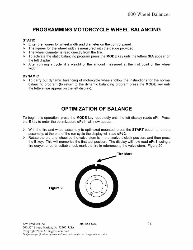
OPTIMIZATION OF BALANCE To begin this operation, press the MODE key repeatedly until the left display reads oPt. Press the E key to enter the optimization; oPt 1 will now appear. With the tire and wheel assembly to optimized mounted, press the START button to run the
assembly, at the end of the run cycle the display will read oPt 2. Rotate the tire and wheel so the valve stem is in the twelve o’clock position, and then press
the E key. This will memorize the first test position. The display will now read oPt 3, using a tire crayon or other suitable tool, mark the tire in reference to the valve stem. Figure 20
Tire Mark
Figure 20
KW Products Inc. 800-553-5953 24. 500 57th Street, Marion, IA 52302 USA Copyright 2004 All Rights Reserved Equipment specifications, options and accessories subject to change without notice.

800 Wheel Balancer
OPTIMIZATION OF BALANCE (continued)
Remove the tire and wheel from the balancer and take to a tire machine. Break the beads and rotate the tire on the rim so that the tire reference mark is now 180 degrees from the valve stem. Re-inflate the tire, and remount on the balancer. Figure 21.
Rotate the tire and wheel by hand until the valve stem is now at the twelve o’clock position,
press the E key, this will memorize the second test position. The display will now read oPt 4. Figure 21
Valve Stem
Figure 21
Press the START
is optimized. If thshow the static imThese figures areassembly.
To continue the optimLED’s are centered. M
Figure 22
KW Products Inc. 500 57th Street, Marion, IACopyright 2004 All RightsEquipment specifications, option
Tire Mark
button to run the assembly. If the display reads oPt yes, the tire and wheel e display reads oPt5, push and hold the STOP button. The left display will balance value, while the right display shows the residual imbalance value. useful in determining if you should continue to try and further optimize the
ization process, rotate the tire and wheel assembly until the positioning ark the tire at the twelve o’clock position. Figure 22
s
New Mark
Valve Stem
Tire Mark
800-553-5953 25. 52302 USA Reserved and accessories subject to change without notice.

800 Wheel Balancer
OPTIMIZATION OF BALANCE (continued)
Remove the tire and wheel assembly from the balancer and take to a tire machine. Break the beads and rotate the tire so that the new mark is in line with the valve stem. Re-inflate the tire, and remount on the balancer. Figure 23
New Mark
Valve Stem
Figure 23
Tire Mark Rotate the tire and wheel assembly by hand so that the valve stem is at the twelve o’clock
position, press the E key to memorize the position. The display will now read oPt6. Press the START button and to run the assembly, if the display reads YES, the optimization
process is complete. If the display reads oPt 7, then you go to step oPt 5 and continue. When it is no longer possible to reduce further imbalance through the optimization, the process ends. Return to the Normal mode and balance in a conventional method.
KW Products Inc. 800-553-5953 26. 500 57th Street, Marion, IA 52302 USA Copyright 2004 All Rights Reserved Equipment specifications, options and accessories subject to change without notice.

800 Wheel Balancer
SPECIAL PROGRAMMING HIGH RESOLUTION WEIGHT DISPLAY The weigh is displayed with an interval of 50 g (1.0 ounce) for truck wheels and an interval
of 5g (0.25 ounce) for car wheels. The imbalance figures can be displayed at high resolution, with an interval of 10g (0.1
ounce) for truck wheels and an interval of 1g (0.01 ounce) for car wheels. Operators enter the command “C 2 1 E” to toggle between the two degrees of resolution:
1. If “C 2 1 E” is pressed in standard resolution, this switches to high resolution. 2. If “C 2 1 E” is pressed in high resolution, this switches to standard resolution.
SWITCHING OFF SOUND 1. To deactivate the “Beep” that sound when keys are pressed and in all other functions, press
the keys “C 1 6 E”. 2. To reactivate the sound press “C 1 6 E” again. ENTERING MEASUREMENTS IN mm Entering wheel measurements in mm does not require any particular operation. Simply write
the figures in mm as they appear on the tire. START UP BY LOWERING THE WHEEL COVER To start the wheel imbalance measuring cycles simply by lowering the wheel cover, press
the keys “C 1 5 E”. If conversely start up is required only after the start button on the panel is pressed (with the
wheel cover already lowered), press “C 1 5 E” again. WEIGHT DISPLAY IN GRAMS OR OUNCES To display the weight in ounces rather than grams press the keys “C 2 0 E”. To return to display in grams press “C 1 8 E”.
ZEROING SMALL GRAM MEASUREMENTS To zero small gram measurements press “C 7 E”. The left display shows the current zeroing
figure. To modify the setting enter a new figure (displayed on the right) and press “E” to confirm the
figure. The same command applies to both truck and car wheels. The two figures are however
fixed at a ratio of 10:1 so that if 40 g is set for the truck program the machine automatically calculates a figure of 4.0 g for the car program. Conversely, if 3.5 g is set in the car program then the machine automatically sets a figure of 35 g for the truck program. The maximum setting figure is 99 g in the truck program (9.9 g in the car program).
NOTE: The small gram zeroing figures must be set in grams. The corresponding zeroing figures in ounces are then calculated by the machine.
KW Products Inc. 800-553-5953 27. 500 57th Street, Marion, IA 52302 USA Copyright 2004 All Rights Reserved Equipment specifications, options and accessories subject to change without notice.

800 Wheel Balancer
CHECKING THE BALANCING OPERATION
Two test procedures are required to ensure that wheel balancing is carried out correctly (the procedures described apply to car wheels but could be used with truck wheels by adjusting the tolerance in the imbalance measurements). CHECKING THE CORRECT OPERATION OF THE BALANCING PROCEDURE The two sides of a wheel are balanced according to the instructions. Then an imbalance is artificially created by adding a one ounce weight on one of the two
sides. The machine should now indicate exactly this imbalance giving both the weight and the position. There might also be a reading for the other side to a max. of .01 ounce. To check the imbalance indicator LED the wheel is rotated until the imbalance position is
reached and indicated by the machine. In this position the test weight should be positioned vertically under the axle (at 6 o’clock). If there is a clearly visible angular deviation then the indicator LED’s have to be corrected. If there is an unacceptable deviation for the readings on the side of the wheel with the test
weight, or if the imbalance indicated for the other side is excessive, then the machine has to be re-calibrated.
CENTERING PRECISION (WHEEL BALANCING QUALITY) For this test the same wheel balanced in the previous test procedure can be used. Remove the test weight. Then release the wheel from the adapting device, rotate it about
35° and then re-lock it. In a test cycle the reading should not exceed a max. imbalance of 10g on each side (15g in
the case of particularly heavy wheels). This error is due to the rim centering tolerance. Precise centering is essential both for this test and for normal balancing procedures. If a large imbalance emerges from this test it is necessary to check for excessive wear, for
play, or for dirt in the parts used to center the wheel.
KW Products Inc. 800-553-5953 28. 500 57th Street, Marion, IA 52302 USA Copyright 2004 All Rights Reserved Equipment specifications, options and accessories subject to change without notice.

800 Wheel Balancer
BASIC MACHINE CALIBRATION FIRST STAGE OF CALIBRATION Fit the cone adapter solidly to the shaft. Press C 7 2 E. The display reads C A L 1. Run a machine cycle with the adapter. When the adapter stops turning the display reads O O. Press C 5 2 6 E to memorize the data.
FOR USE WITH CAR AND TRUCK WHEELS After completing the stage described above (“First stage of calibration”) proceed as follows: Second stage of calibration Mount a medium-sized car wheel in good condition (diameter 14") on the cone adapter and
fix it well. Remove any weights that are already on the wheel. Set the wheel data as follows:
1. Press key 3 and set the rim width in inches (e.g.: 6.0 or 5.5 etc.) then press E. Figure 13 2. Press key 4 and set the wheel diameter in inches (e.g.: 13" or 14") then press E. Figure
13 3. Press key 5 (Figure 13) and set the wheel distance in mm from the body of the wheel
balancer (e.g.: 80 mm, 65 mm etc.), this distance is shown on the graduated scale, then press E. Figure 15
Press STOP. Press C 1 9 E The display reads C A L 4 Run a measuring cycle. When the wheel stops turning, the display reads C A L 5 Type 1 O O E (if the weight used for the automatic calibration is 80 g then type 8 0 E). The display reads C A L 6 Position the 3.5 ounce weight on the inside of the wheel. Run a measuring cycle. When the wheel stops turning, the display reads C A L 7. Remove the 100 g weight form the inside of the wheel and position it on the outside in a
directly opposite location (in the symmetrically opposite position). Run a measuring cycle. When the wheel stops turning, the display reads O O Press STOP C 5 2 6 E to memorize the data.
Calibration is now complete (and does not need to be repeated).
KW Products Inc. 800-553-5953 29. 500 57th Street, Marion, IA 52302 USA Copyright 2004 All Rights Reserved Equipment specifications, options and accessories subject to change without notice.

800 Wheel Balancer
BASIC MACHINE CALIBRATION (continued) FOR USE WITH ONLY TRUCK WHEELS After completing the stage described above. Important! The first stage is conducted in car mode (with the truck program selection indicator off). For the two subsequent stages, either a car wheel (with car wheel adapter) or truck wheel can be used. If a car wheel is used, proceed to the second stage of calibration exactly as described in the
previous paragraph (“For use with car and truck wheels”). If a truck wheel is used, the procedure is similar to that described for the car wheel.
1. First, change to the truck wheel program by pressing C MODE (in the 7th step in the procedure). The truck mode indicator lights up.
2. The wheel dimensions as described above should be set with care, in particular as regards width and distance (step 8 in the procedure).
3. Use a weight of 10.5 ounces for automatic calibration rather than 3.5 ounces (and so in step 14 of the procedure the figure 3 5 0 E must be entered).
KW Products Inc. 800-553-5953 30. 500 57th Street, Marion, IA 52302 USA Copyright 2004 All Rights Reserved Equipment specifications, options and accessories subject to change without notice.

800 Wheel Balancer
SELF-DIAGNOSIS TEMPORARY BALANCING OF A WHEEL When balancing a wheel without weights for the purpose of testing the balancing machine, press “C 7 5 E” and then start up normally. In this way the balancing machine registers the imbalance figures and cancels them. This function cannot be memorized and is canceled as soon as the machine is switched off, or by pressing “C 5 3 O E”. +5 V VOLTAGE DISPLAY To display this voltage press the buttons “C 2 E”. The left display reads “t2” and the voltage is shown on the right, and should be between 4.6 and 4.9. +2.5 V VOLTAGE DISPLAY To display this voltage press the buttons “C 1 E”. The left display reads “t1” and the voltage is shown on the right, and should be between 2.3 and 2.5. PICK-UP VOLTAGE DISPLAY To display the voltage taken in the last measurement, press “C6 E” and on the left display the internal pick-up reading appears and on the right the outer pick-up. The correct functioning of the pick-ups can be checked as follows: the voltage of the inner pick-up should always be smaller than the external pickup reading. The ratio between the external and internal pick-up readings should never exceed 3.5 and should never be less than 1.5. PICK-UP PHASE DISPLAY To display the phase of the last measurement, press “C 1 7 E” and the internal pick-up reading appears on the left-hand display, and on the right the external reading. The correct functioning of the pick-up can be checked as follows: start up with only the flange with the sample weight fitted. The difference between the two angles should be 180° (0 - 180° +/- 1°) CHECKING MOTOR ROTATION SPEED To check motor rotation in revolutions per minute, press “C 5 E” and then “START”. The rpm for the first minute will be displayed on the right. The minimum acceptable figure at 50 Hz is 162 rpm and the maximum 172 rpm The minimum acceptable figure at 60 HZ is 195 rpm and the maximum 205 rpm MEMORIZING DATA It must be remembered that any setting operation or function modification must be memorized before starting a new work cycle. This is done by pressing “STOP C 5 2 6 E”.
KW Products Inc. 800-553-5953 31. 500 57th Street, Marion, IA 52302 USA Copyright 2004 All Rights Reserved Equipment specifications, options and accessories subject to change without notice.

800 Wheel Balancer
TROUBLESHOOTING GUIDE
DISPLAY FAULT CAUSE POSSIBLE SOLUTIONS The display does not light up
The board has no power.
No external supply or lack of one phase. Fuses F3-F4 blown in the electrical system. See electrical circuit diagrams #652897. Fuses F1-F2 blown on the electrical board. See electrical circuit diagrams #652898.
Check that the phase and neutral are connected to the balancing machine. Replace fuses F3 and/or F4 (the repeated blowing of these fuses indicates an electrical malfunction Replace fuses F1 and/or F2. The repeated blowing of these fuses indicates an electrical malfunction.
E 00 Non-existent function error.
Wrong function code entered.
Check the code in this manual and enter it.
E 01 “E 01” appears when the machine is switched on.
The board has lost its calibration settings memorized during production.
Conduct the full calibration procedure for the balancing machine.
E 02 “E 02” appears when the machine is switched on.
The board’s operating memory is not working.
Replace the board.
E 03 The motor turns in the wrong direction.
When START was pressed or the cover lowered, the wheel was turning in the reverse direction.
Ensure that the wheel is stationary and not turning in the reverse direction when starting up.
E 04 The machine takes a long time to measure the imbalance and after about 30 seconds an “E 04” message is displayed.
The motor is unable to achieve the speed required for accurate balancing. Fault in the electrical system. Fault on the electronic board.
Check the supply voltage (it might be low). Replace the electrical components. Replace the electronic board.
E 05 “E 05” is displayed after the second cycle of calibration.
The sample weight is not screwed on.
Re-start calibration and after the first cycle screw on the sample weight before starting the second cycle.
E 06 When START is pressed “E 06” is displayed.
The guard cover is not lowered. Guard cover microswitch is faulty. See electrical circuit diagrams #652897.
Lower the cover when the wheel is fixed. Replace the microswitch.
KW Products Inc. 800-553-5953 32. 500 57th Street, Marion, IA 52302 USA Copyright 2004 All Rights Reserved Equipment specifications, options and accessories subject to change without notice.

800 Wheel Balancer
TROUBLESHOOTING GUIDE (continued)
DISPLAY FAULT CAUSE POSSIBLE SOLUTIONS E 07 “E 07” is displayed after
a calibration cycle. The phase difference between the two pick-ups is too large.
Check that the calibration weight is correctly fitted. Check the stability of the machine. Instability can cause excessive vibration. If the problem persists after having correctly fixed the machine to the floor, check the connection of the pick-ups and the electronic board. Replace if necessary.
E 08 “E 08” is displayed after the second calibration cycle.
The left pick-up is not correctly connected, is defective, or has a broken wire.
Check the connection of the left pick-up. Replace if necessary.
E 09 “E 09” is displayed after the second calibration cycle.
The right pick-up is not correctly connected, is defective, or has a broken wire.
Check the connection of the right pick-up. Replace if necessary.
E 10 “E 10” is displayed after a cycle.
Something is stopping the wheel from turning or it is turning too slowly. The motor is faulty. Fault in the optoelectronic position sensors.
The lift trolley is not fully lowered. Check the electrical
elements. Check the optoelectronics.
Replace if necessary. E 11 “E 11” is displayed after
a cycle. Something is stopping the wheel from turning or it is turning too slowly. The motor is faulty. Fault in the optoelectronic position sensors.
The lift trolley is not fully lowered. Check the electrical
elements. Check the optoelectronics.
Replace if necessary. E 14 “E 14” is displayed. The +5V supply is incorrect. Replace the electrical
board. E 17 “E 17” is displayed after
a cycle. Wheel imbalance is too great and the weight is outside the correction range. The weight required to balance the wheel is greater than 400g for car wheels and 2kg for truck wheels.
Check that the wheel is correctly fixed to the adapter. If in car wheel mode (truck
LED off) and the wheel to be balanced is a truck wheel, change to the truck wheel program. Establish the external
position and fit a weight (100g for car wheels and 350g for truck wheels) and run another cycle.
KW Products Inc. 800-553-5953 33. 500 57th Street, Marion, IA 52302 USA Copyright 2004 All Rights Reserved Equipment specifications, options and accessories subject to change without notice.

800 Wheel Balancer
TROUBLESHOOTING GUIDE (continued)
DISPLAY FAULT CAUSE POSSIBLE SOLUTIONS E 18 “E 18” is displayed after
a cycle. Wheel data not entered. Enter the wheel data on the
keyboard. E 19 “E 19” is displayed after
a cycle. The signal reading at the right pick-up is lower than the left pick-up.
The connections to the two pick-ups might be inverted. Exchange if necessary.
E 20 “E 20” is displayed during measuring cycles.
The wheel speed dropped below the minimum 42 rpm for trucks.
The wheel is too light for measuring with the truck program. Change to the car program (C key and MODE) and start another measuring cycle.
E 21 The electronic board has registered danger due to the excessive rotation of the wheel during periods of machine inactivity (the axle is rotating at high speed without the operator pressing START). The electrical power supply to the power system is disabled.
Possible error in the electrical power system.
Switch off the machine, lower the cover and switch the machine on again without moving the wheel. If the condition persists, the electrical board should be checked. Replace if necessary.
KW Products Inc. 800-553-5953 34. 500 57th Street, Marion, IA 52302 USA Copyright 2004 All Rights Reserved Equipment specifications, options and accessories subject to change without notice.

800 Wheel Balancer
ROUTINE MAINTENANCE CLEANING THE MACHINE AND USER MAINTENANCE In order to guarantee the correct operation and efficiency of the machine it is essential to carry out periodic routine maintenance. Routine maintenance operations must be conducted by the user in accordance with the manufacturer’s instructions given below. Before carrying out any maintenance or cleaning operations, switch off the machine using the main switch and remove the plug from the socket. MECHANICAL PARTS The centering cones, adapter devices and the Kwik-Nut must be kept clean and lightly lubricated with non-corrosive oil even when not being used. The quality of the balancing depends significantly on the condition of these parts. LUBRICATOR: check and adjust the level of oil in the lubricator. The level should not go outside the minimum and maximum levels indicated on it. Top up if necessary. WATER SEPARATOR: Periodically release the condensation that accumulates in the water trap.
TECHNICAL ASSISTANCE AND SPARE PARTS For any malfunctions, consult the Troubleshooting Guide in this manual. Any malfunctions other than those listed should be checked by a qualified technician. For prompt assistance, please have the machine mode and serial number ready when you place your call. Any SPARE PARTS must be ordered from Kwik-Way Products or an authorized distributor the manufacturer denies all responsibility for damage or malfunctions resulting from use of non-original substituted parts.
KW Products Inc. 800-553-5953 35. 500 57th Street, Marion, IA 52302 USA Copyright 2004 All Rights Reserved Equipment specifications, options and accessories subject to change without notice.
800 Wheel Balancer
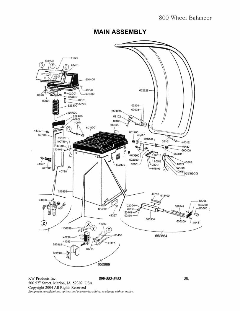
MAIN ASSEMBLY
KW Products Inc. 800-553-5953 36. 500 57th Street, Marion, IA 52302 USA Copyright 2004 All Rights Reserved Equipment specifications, options and accessories subject to change without notice.

800 Wheel Balancer
ARBOR ASSEMBLY
KW Products Inc. 800-553-5953 37. 500 57th Street, Marion, IA 52302 USA Copyright 2004 All Rights Reserved Equipment specifications, options and accessories subject to change without notice.
800 Wheel Balancer
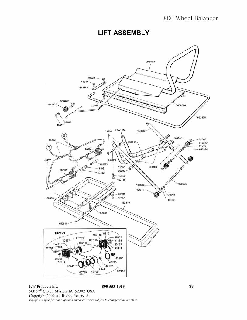
LIFT ASSEMBLY
KW Products Inc. 800-553-5953 38. 500 57th Street, Marion, IA 52302 USA Copyright 2004 All Rights Reserved Equipment specifications, options and accessories subject to change without notice.

800 Wheel Balancer
WIRING DIAGRAM – 115V
KW Products Inc. 800-553-5953 39. 500 57th Street, Marion, IA 52302 USA Copyright 2004 All Rights Reserved Equipment specifications, options and accessories subject to change without notice.

800 Wheel Balancer
WIRING DIAGRAM – 230V
KW Products Inc. 800-553-5953 40. 500 57th Street, Marion, IA 52302 USA Copyright 2004 All Rights Reserved Equipment specifications, options and accessories subject to change without notice.

KW Products Inc. 500 57th St., Marion, IA 52302 USA
319/377-9421 319/377-9101 (FAX)
800/553-5953 www.kwik-way.com