
8. Visibility and Class Diagrams
14
12/25/2014 1 | Visibility and Class Diagrams | Visibility and Class Diagrams MTI8305 - Software Modeling 2 Design Model: Determining Visibility Objectives Identify four kinds of visibility Design to establish visibility Illustrate kinds of visibility in the UML notation Visibility between Objects Visibility is the ability of one object to see or have reference to another. The designs created for the system events (enterItem in Figure 11.1) illustrate messages between objects. For a sender object to send a message to a receiver object, the sender must be visible to the receiver – the sender must have some kind of reference or pointer to receiver object. When creating a design of interacting objects, it is necessary to ensure that the visibility is present to support message interaction.
description
visibility and class diagrams - software modeling
Transcript of 8. Visibility and Class Diagrams
12/25/2014
1
|
Visibility and Class Diagrams
|Visibility
and Class
Diagrams
MTI8305 - Software Modeling 2
Design Model: Determining Visibility
� Objectives
� Identify four kinds of visibility
� Design to establish visibility
� Illustrate kinds of visibility in the UML notation
� Visibility between Objects
� Visibility is the ability of one object to see or have reference toanother. The designs created for the system events (enterItem inFigure 11.1) illustrate messages between objects.
� For a sender object to send a message to a receiver object, thesender must be visible to the receiver – the sender must havesome kind of reference or pointer to receiver object.
� When creating a design of interacting objects, it is necessary toensure that the visibility is present to support messageinteraction.
12/25/2014
2
|Visibility
and Class
Diagrams
MTI8305 - Software Modeling 3
Visibility between Objects
: RegisterenterItem
(itemID, quantity)
: ProductCatalog
spec := getSpecification( itemID )
{public void enterItem( itemID, qty ){ ... spec = catalog.getSpecification(itemID) ...}}
class Register{ ... private ProductCatalog catalog; ...}
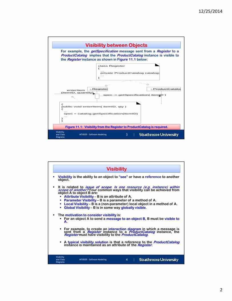
Figure 11.1: Visibility from the Register to ProductCatalog is required.
For example, the getSpecification message sent from a Register to a
ProductCatalog implies that the ProductCatalog instance is visible to
the Register instance as shown in Figure 11.1 below:
|Visibility
and Class
Diagrams
MTI8305 - Software Modeling 4
Visibility
� Visibility is the ability to an object to “see” or have a reference to anotherobject.
� It is related to issue of scope: Is one resource (e.g. instance) withinscope of another? Four common ways that visibility can be achieved fromobject A to object B are:� Attribute Visibility – B is an attribute of A.� Parameter Visibility – B is a parameter of a method of A.� Local Visibility – B is a (non-parameter) local object in a method of A.� Global Visibility – B is in some way globally visible.
� The motivation to consider visibility is:� For an object A to send a message to an object B, B must be visible to
A.
� For example, to create an interaction diagram in which a message issent from a Register instance to a ProductCatalog instance, theRegister must have visibility to the ProductCatalog.
� A typical visibility solution is that a reference to the ProductCataloginstance is maintained as an attribute of the Register.
12/25/2014
3
|Visibility
and Class
Diagrams
MTI8305 - Software Modeling 5
1. Attribute Visibility
� Attribute visibility from A to B exists when B is an attribute
of A, a common visibility in object-oriented systems.
� It is a relatively permanent visibility because it persists as
long as A and B exist.
� To illustrate, in a Java class definition, a Register instance
may have attribute visibility to a ProductCatalog, since it is
an attribute (Java instance variable) of the Register
public class Register {
…
private ProductCatalog catalog {
….
}
}
|Visibility
and Class
Diagrams
MTI8305 - Software Modeling 6
: RegisterenterItem
(itemID, quantity)
: ProductCatalog
spec := getSpecification( itemID )
{public void enterItem(itemID, qty){ ... spec = catalog.getSpecification(itemID) ...}}
class Register{ ... private ProductCatalog catalog; ...}
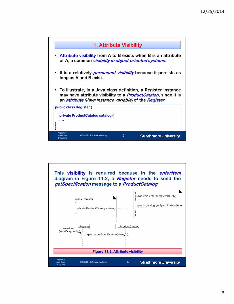
Figure 11.2: Attribute visibility
This visibility is required because in the enterItemdiagram in Figure 11.2, a Register needs to send the
getSpecification message to a ProductCatalog
12/25/2014
4
|Visibility
and Class
Diagrams
MTI8305 - Software Modeling 7
2. Parameter Visibility
� Parameter visibility from A to B exists when B is passedas a parameter to a method of A and second mostcommon visibility in object-oriented systems afterattribute visibility.
� It is a relatively temporary visibility because it persistsonly within the scope of the method.
� It is common to transform parameter visibility intoattribute visibility.
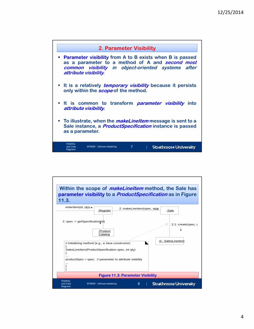
� To illustrate, when the makeLineItem message is sent to aSale instance, a ProductSpecification instance is passedas a parameter.
|Visibility
and Class
Diagrams
MTI8305 - Software Modeling 8
2: makeLineItem(spec, qty)enterItem(id, qty)
2: spec := getSpecification(id)2.1: create(spec, qty)
:Register :Sale
:ProductCatalog
sl : SalesLineItem// initializing method (e.g., a Java constructor){SalesLineItem(ProductSpecification spec, int qty){...productSpec = spec; // parameter to attribute visibility...}}
Figure 11.3: Parameter Visibility
Within the scope of makeLineItem method, the Sale has
parameter visibility to a ProductSpecification as in Figure
11.3.
12/25/2014
5
|Visibility
and Class
Diagrams
MTI8305 - Software Modeling 9
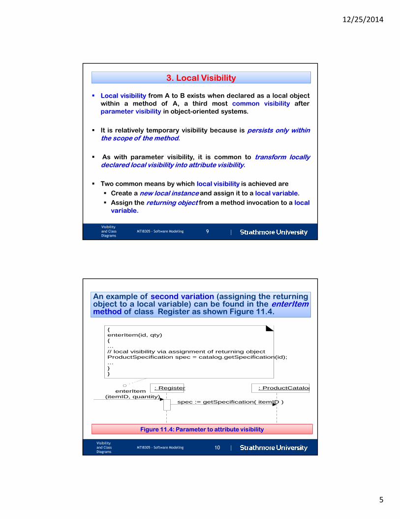
3. Local Visibility
� Local visibility from A to B exists when declared as a local object
within a method of A, a third most common visibility after
parameter visibility in object-oriented systems.
� It is relatively temporary visibility because is persists only withinthe scope of the method.
� As with parameter visibility, it is common to transform locallydeclared local visibility into attribute visibility.
� Two common means by which local visibility is achieved are
� Create a new local instance and assign it to a local variable.
� Assign the returning object from a method invocation to a local
variable.
|Visibility
and Class
Diagrams
MTI8305 - Software Modeling 10
: RegisterenterItem
(itemID, quantity)
: ProductCatalog
spec := getSpecification( itemID )
{enterItem(id, qty){...// local visibility via assignment of returning objectProductSpecification spec = catalog.getSpecification(id);...}}
Figure 11.4: Parameter to attribute visibility
An example of second variation (assigning the returningAn example of second variation (assigning the returningobject to a local variable) can be found in the enterItemmethod of class Register as shown Figure 11.4.
12/25/2014
6
|Visibility
and Class
Diagrams
MTI8305 - Software Modeling 11
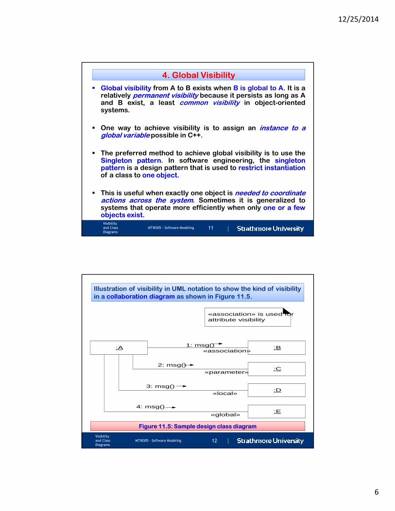
4. Global Visibility
� Global visibility from A to B exists when B is global to A. It is arelatively permanent visibility because it persists as long as Aand B exist, a least common visibility in object-orientedsystems.
� One way to achieve visibility is to assign an instance to aglobal variable possible in C++.
� The preferred method to achieve global visibility is to use theSingleton pattern. In software engineering, the singletonpattern is a design pattern that is used to restrict instantiationof a class to one object.
� This is useful when exactly one object is needed to coordinateactions across the system. Sometimes it is generalized tosystems that operate more efficiently when only one or a fewobjects exist.
|Visibility
and Class
Diagrams
MTI8305 - Software Modeling 12
:A :B1: msg()
:C2: msg()
:D3: msg()
«association»
«parameter»
«local»
:E4: msg()
«global»
«association» is used forattribute visibility
Figure 11.5: Sample design class diagram
Illustration of visibility in UML notation to show the kind of visibility
in a collaboration diagram as shown in Figure 11.5.
12/25/2014
7
|Visibility
and Class
Diagrams
MTI8305 - Software Modeling13
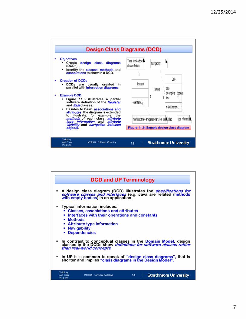
Design Class Diagrams (DCD)
� Objectives
� Create design class diagrams(DCDs).
� Identify the classes, methods andassociations to show in a DCD.
� Creation of DCDs
� DCDs are usually created inparallel with interaction diagrams
� Example DCD
� Figure 11.6 illustrates a partialsoftware definition of the Registerand Sale classes.
� Besides to basic associations andattributes, the diagram is extendedto illustrate, for example, themethods of each class, attributetype information and attributevisibility and navigation betweenobjects.
Register
enterItem(...)
Sale
dateisComplete : Booleantime
makeLineItem(...)
Captures
Navigability
1 1
Three section box forclass definition.
methods; there are parameters, but unspecified type information
Figure 11.6: Sample design class diagram
|Visibility
and Class
Diagrams
MTI8305 - Software Modeling 14
DCD and UP Terminology
� A design class diagram (DCD) illustrates the specifications forsoftware classes and interfaces (e.g. Java are related methodswith empty bodies) in an application.
� Typical information includes:� Classes, associations and attributes� Interfaces with their operations and constants� Methods� Attribute type information� Navigability� Dependencies
� In contrast to conceptual classes in the Domain Model, designclasses in the DCDs show definitions for software classes ratherthan real-world concepts.
� In UP it is common to speak of “design class diagrams”, that isshorter and implies “class diagrams in the Design Model”.
12/25/2014
8
|Visibility
and Class
Diagrams
MTI8305 - Software Modeling 15
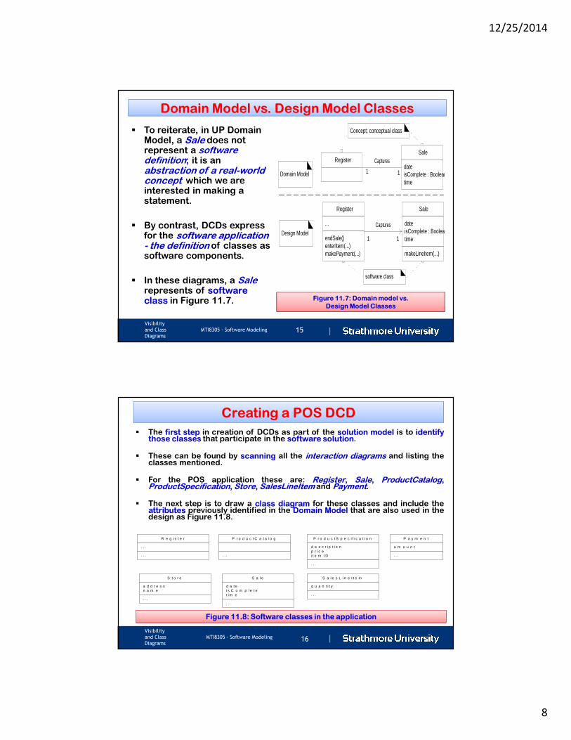
Domain Model vs. Design Model Classes
� To reiterate, in UP Domain Model, a Sale does not represent a software definition; it is an abstraction of a real-world concept which we are interested in making a statement.
� By contrast, DCDs express for the software application - the definition of classes as software components.
� In these diagrams, a Salerepresents of software class in Figure 11.7.
Register
...
endSale()enterItem(...)makePayment(...)
Sale
dateisComplete : Booleantime
makeLineItem(...)
Captures
RegisterSale
dateisComplete : Booleantime
Captures
software class
1 1
11Domain Model
Design Model
Concept; conceptual class
Figure 11.7: Domain model vs.
Design Model Classes
|Visibility
and Class
Diagrams
MTI8305 - Software Modeling 16
Creating a POS DCD
� The first step in creation of DCDs as part of the solution model is to identifythose classes that participate in the software solution.
� These can be found by scanning all the interaction diagrams and listing theclasses mentioned.
� For the POS application these are: Register, Sale, ProductCatalog,ProductSpecification, Store, SalesLineItem and Payment.
� The next step is to draw a class diagram for these classes and include theattributes previously identified in the Domain Model that are also used in thedesign as Figure 11.8.
R e g i s t e r
. . .
. . .
S a l e
d a t ei s C o m p l e t et i m e
. . .
S a l e s L i n e I t e m
q u a n t i t y
. . .
P r o d u c t C a t a l o g
. . .
P r o d u c t S p e c i f i c a t i o n
d e s c r i p t i o np r i c ei t e m I D
. . .
S t o r e
a d d r e s sn a m e
. . .
P a y m e n t
a m o u n t
. . .
Figure 11.8: Software classes in the application
12/25/2014
9
|Visibility
and Class
Diagrams
MTI8305 - Software Modeling 17
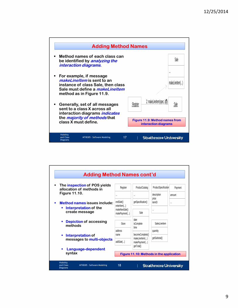
Adding Method Names
� Method names of each class can be identified by analyzing the interaction diagrams.
� For example, if message makeLineItem is sent to an instance of class Sale, then class Sale must define a makeLineItemmethod as in Figure 11.9.
� Generally, set of all messages sent to a class X across all interaction diagrams indicates the majority of methods that class X must define.
:Register :Sale2: makeLineItem(spec, qty)
Sale
...
makeLineItem(...)
Figure 11.9: Method names from
interaction diagrams
|Visibility
and Class
Diagrams
MTI8305 - Software Modeling 18
Adding Method Names cont’d
� The inspection of POS yields allocation of methods in Figure 11.10.
� Method names issues include:
� Interpretation of the create message
� Depiction of accessing methods
� Interpretation of messages to multi-objects
� Language-dependentsyntax
SalesLineItem
quantity
getSubtotal()
ProductCatalog
...
getSpecification()
ProductSpecification
descriptionpriceitemID
...
Store
addressname
addSale(...)
Payment
amount
...
Register
...
endSale()enterItem(...)makeNewSale()makePayment(...) Sale
dateisCompletetime
becomeComplete()makeLineItem(...)makePayment(...)getTotal()
Figure 11.10: Methods in the application
12/25/2014
10
|Visibility
and Class
Diagrams
MTI8305 - Software Modeling 19
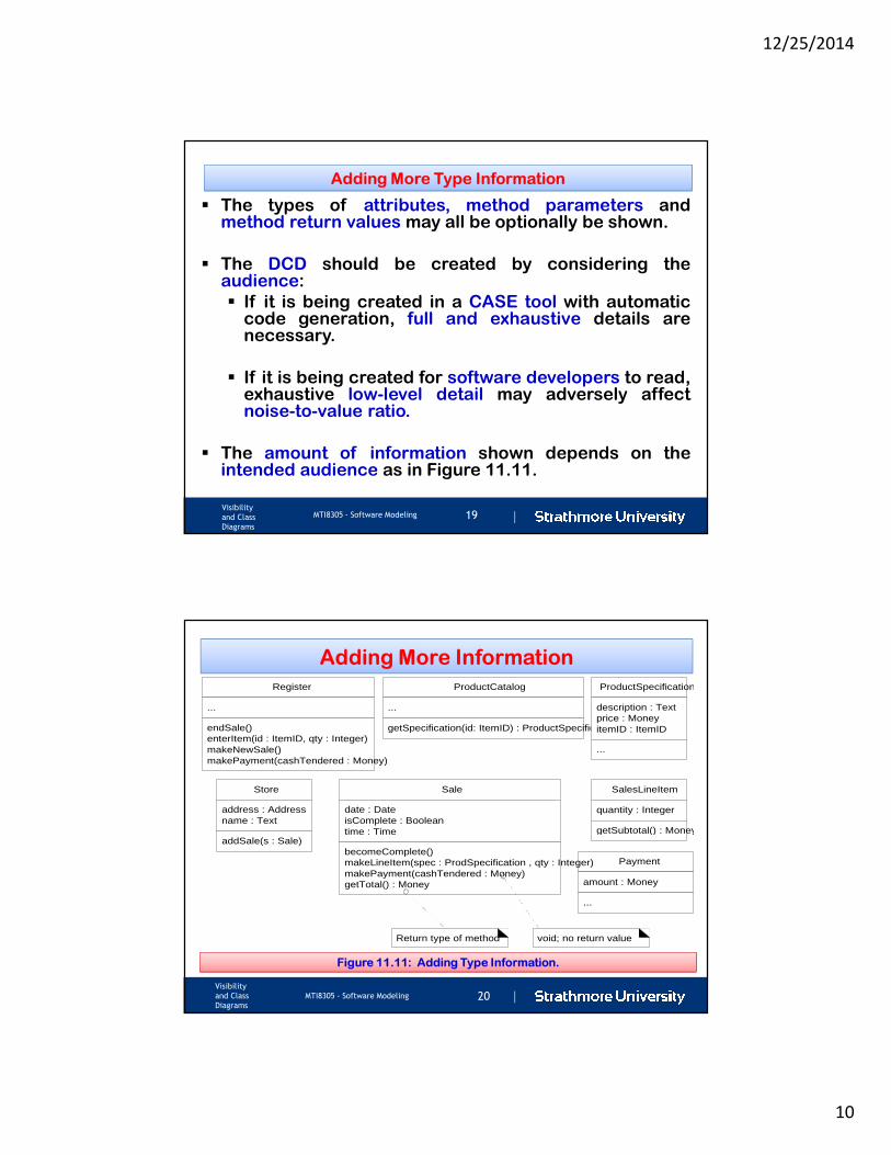
Adding More Type Information
� The types of attributes, method parameters andmethod return values may all be optionally be shown.
� The DCD should be created by considering theaudience:
� If it is being created in a CASE tool with automaticcode generation, full and exhaustive details arenecessary.
� If it is being created for software developers to read,exhaustive low-level detail may adversely affectnoise-to-value ratio.
� The amount of information shown depends on theintended audience as in Figure 11.11.
|Visibility
and Class
Diagrams
MTI8305 - Software Modeling 20
Adding More Information
SalesLineItem
quantity : Integer
getSubtotal() : Money
ProductCatalog
...
getSpecification(id: ItemID) : ProductSpecification
ProductSpecification
description : Textprice : MoneyitemID : ItemID
...
Store
address : Addressname : Text
addSale(s : Sale)
Payment
amount : Money
...
Register
...
endSale()enterItem(id : ItemID, qty : Integer)makeNewSale()makePayment(cashTendered : Money)
Sale
date : DateisComplete : Booleantime : Time
becomeComplete()makeLineItem(spec : ProdSpecification , qty : Integer)makePayment(cashTendered : Money)getTotal() : Money
Return type of method void; no return value
Figure 11.11: Adding Type Information.
12/25/2014
11
|Visibility
and Class
Diagrams
MTI8305 - Software Modeling 21
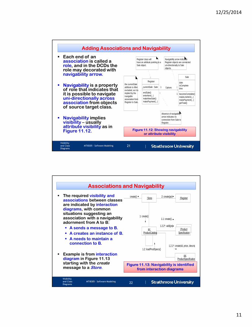
Adding Associations and Navigability
� Each end of an association is called a role, and in the DCDs the role may decorated with navigability arrow.
� Navigability is a property of role that indicates that it is possible to navigate uni-directionally across association from objects of source target class.
� Navigability implies visibility – usually attribute visibility as in Figure 11.12.
Captures
Register
currentSale : Sale
endSale()enterItem(...)makeNewSale()makePayment(...)
Sale
dateisCompletetime
becomeComplete()makeLineItem(...)makePayment(...)getTotal()
Navigability arrow indicatesRegister objects are connecteduni-directionally to Saleobjects.
Absence of navigabilityarrow indicates noconnection from Sale toRegister.
Register class willhave an attribute pointing to aSale object.
1
1
the currentSaleattribute is oftenexcluded, as it isimplied by thenavigableassociation fromRegister to Sale.
Figure 11.12: Showing navigability
or attribute visibility
|Visibility
and Class
Diagrams
MTI8305 - Software Modeling22
Associations and Navigability
� The required visibility and associations between classes are indicated by interaction diagrams, with common situations suggesting an association with a navigability adornment from A to B:
� A sends a message to B.
� A creates an instance of B.
� A needs to maintain a connection to B.
� Example is from interaction diagram in Figure 11.13 starting with the create message to a Store.
:Store :Register
pc:ProductCatalog
create() 2: create(pc)
1: create()
1.2: loadProdSpecs()
:ProductSpecification
1.1: create()
1.2.2*: add(ps)
1.2.1*: create(id, price, description)
ps:ProductSpecification
Figure 11.13: Navigability is identified
from interaction diagrams
12/25/2014
12
|Visibility
and Class
Diagrams
MTI8305 - Software Modeling 23
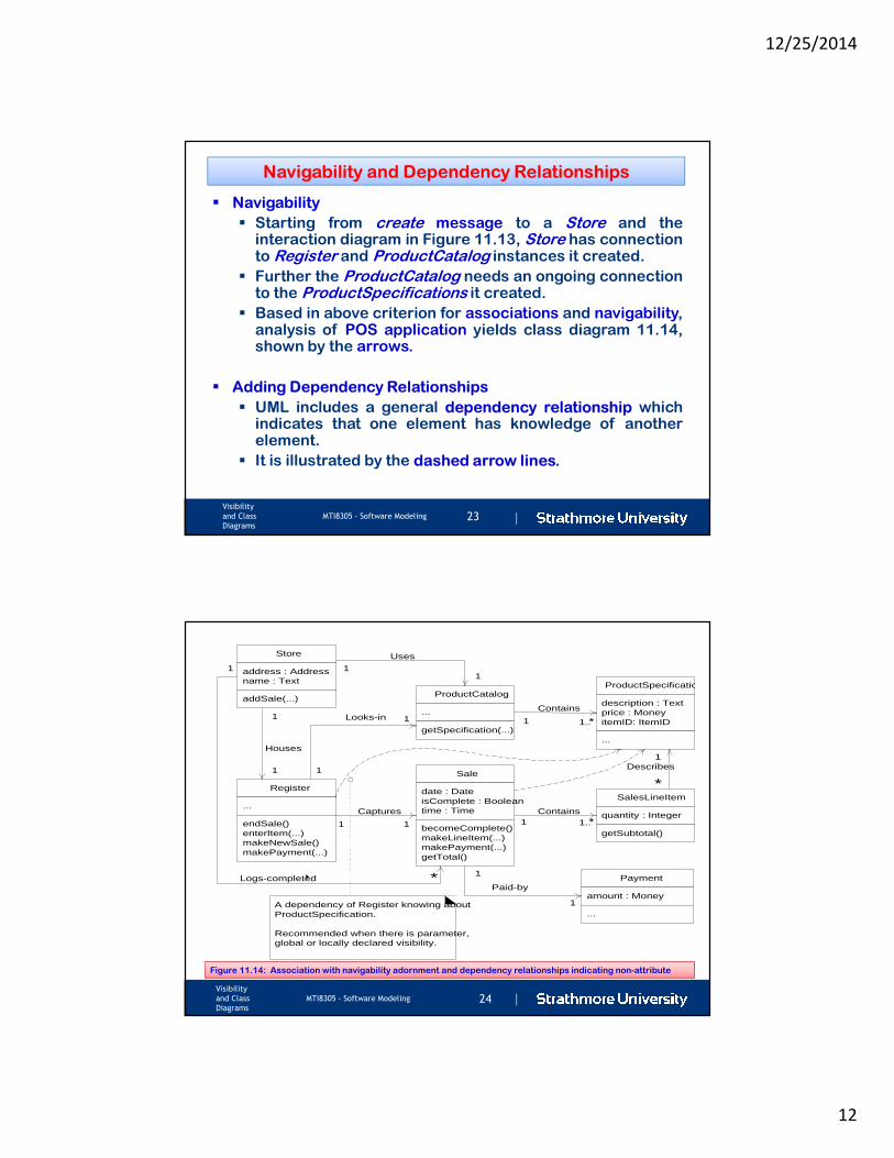
Navigability and Dependency Relationships
� Navigability
� Starting from create message to a Store and theinteraction diagram in Figure 11.13, Store has connectionto Register and ProductCatalog instances it created.
� Further the ProductCatalog needs an ongoing connectionto the ProductSpecifications it created.
� Based in above criterion for associations and navigability,analysis of POS application yields class diagram 11.14,shown by the arrows.
� Adding Dependency Relationships
� UML includes a general dependency relationship whichindicates that one element has knowledge of anotherelement.
� It is illustrated by the dashed arrow lines.
|Visibility
and Class
Diagrams
MTI8305 - Software Modeling 24
SalesLineItem
quantity : Integer
getSubtotal()
ProductCatalog
...
getSpecification(...)
ProductSpecification
description : Textprice : MoneyitemID: ItemID
...
Store
address : Addressname : Text
addSale(...)
Payment
amount : Money
...
Contains
1..*
Contains1..*
Register
...
endSale()enterItem(...)makeNewSale()makePayment(...)
Sale
date : DateisComplete : Booleantime : Time
becomeComplete()makeLineItem(...)makePayment(...)getTotal()
Captures
Houses
Uses
Looks-in
Paid-by
Describes
1 1
1
1 1
1
11
1
1
1
1
1
*
A dependency of Register knowing aboutProductSpecification.
Recommended when there is parameter,global or locally declared visibility.
Logs-completed4 *
1
Figure 11.14: Association with navigability adornment and dependency relationships indicating non-attribute
12/25/2014
13
|Visibility
and Class
Diagrams
MTI8305 - Software Modeling 25
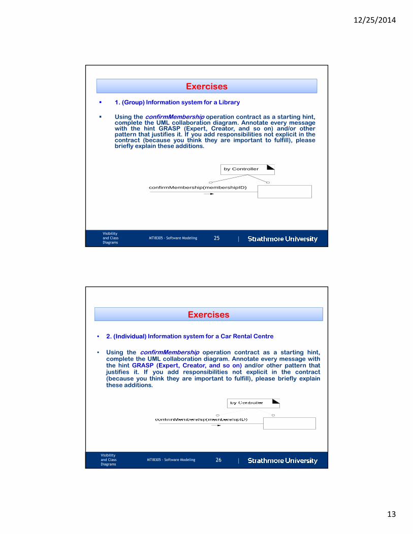
Exercises
� 1. (Group) Information system for a Library
� Using the confirmMembership operation contract as a starting hint,complete the UML collaboration diagram. Annotate every messagewith the hint GRASP (Expert, Creator, and so on) and/or otherpattern that justifies it. If you add responsibilities not explicit in thecontract (because you think they are important to fulfill), pleasebriefly explain these additions.
confirmMembership(membershipID)
by Controller
|Visibility
and Class
Diagrams
MTI8305 - Software Modeling 26
Exercises
• 2. (Individual) Information system for a Car Rental Centre
• Using the confirmMembership operation contract as a starting hint,complete the UML collaboration diagram. Annotate every message withthe hint GRASP (Expert, Creator, and so on) and/or other pattern thatjustifies it. If you add responsibilities not explicit in the contract(because you think they are important to fulfill), please briefly explainthese additions.

12/25/2014
14
|
Ole Sangale Road, Madaraka Estate. PO Box 59857-00200, Nairobi, Kenya
Tel +254 (0)20 606155, 606268, 606380 Fax +254 (0)20 607498
Mobile +254 (0)722 25 428, (0)733 618 135 Email [email protected]
www.strathmore.edu


![class Diagrams uml diagrams-basic [for educational purpose only]](https://static.fdocuments.net/doc/165x107/577d2fe81a28ab4e1eb2f5c6/class-diagrams-uml-diagrams-basic-for-educational-purpose-only.jpg)
