8 NCR 20 Issue 8/98 NELCROSS DILUTION VALVE CONTROL SYSTEM · NELCROSS DILUTION VALVE CONTROL...
4
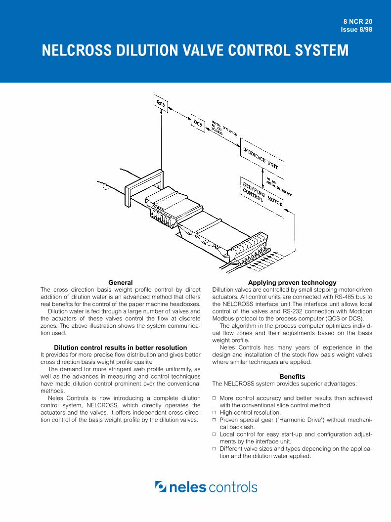
NELCROSS DILUTION VALVE CONTROL SYSTEM 8 NCR 20 Issue 8/98 General The cross direction basis weight profile control by direct addition of dilution water is an advanced method that offers real benefits for the control of the paper machine headboxes. Dilution water is fed through a large number of valves and the actuators of these valves control the flow at discrete zones. The above illustration shows the system communica- tion used. Dilution control results in better resolution It provides for more precise flow distribution and gives better cross direction basis weight profile quality. The demand for more stringent web profile uniformity, as well as the advances in measuring and control techniques have made dilution control prominent over the conventional methods. Neles Controls is now introducing a complete dilution control system, NELCROSS, which directly operates the actuators and the valves. It offers independent cross direc- tion control of the basis weight profile by the dilution valves. Applying proven technology Dillution valves are controlled by small stepping-motor-driven actuators. All control units are connected with RS-485 bus to the NELCROSS interface unit The interface unit allows local control of the valves and RS-232 connection with Modicon Modbus protocol to the process computer (QCS or DCS). The algorithm in the process computer optimizes individ- ual flow zones and their adjustments based on the basis weight profile. Neles Controls has many years of experience in the design and installation of the stock flow basis weight valves where similar techniques are applied. Benefits The NELCROSS system provides superior advantages: ▫ More control accuracy and better results than achieved with the conventional slice control method. ▫ High control resolution. ▫ Proven special gear ("Harmonic Drive") without mechani- cal backlash. ▫ Local control for easy start-up and configuration adjust- ments by the interface unit. ▫ Different valve sizes and types depending on the applica- tion and the dilution water applied.
Transcript of 8 NCR 20 Issue 8/98 NELCROSS DILUTION VALVE CONTROL SYSTEM · NELCROSS DILUTION VALVE CONTROL...
NELCROSS DILUTION VALVE CONTROL SYSTEM
8 NCR 20Issue 8/98
General
The cross direction basis weight profile control by directaddition of dilution water is an advanced method that offersreal benefits for the control of the paper machine headboxes.
Dilution water is fed through a large number of valves andthe actuators of these valves control the flow at discretezones. The above illustration shows the system communica-tion used.
Dilution control results in better resolution
It provides for more precise flow distribution and gives bettercross direction basis weight profile quality.
The demand for more stringent web profile uniformity, aswell as the advances in measuring and control techniqueshave made dilution control prominent over the conventionalmethods.
Neles Controls is now introducing a complete dilutioncontrol system, NELCROSS, which directly operates theactuators and the valves. It offers independent cross direc-tion control of the basis weight profile by the dilution valves.
Applying proven technology
Dillution valves are controlled by small stepping-motor-drivenactuators. All control units are connected with RS-485 bus tothe NELCROSS interface unit The interface unit allows localcontrol of the valves and RS-232 connection with ModiconModbus protocol to the process computer (QCS or DCS).
The algorithm in the process computer optimizes individ-ual flow zones and their adjustments based on the basisweight profile.
Neles Controls has many years of experience in thedesign and installation of the stock flow basis weight valveswhere similar techniques are applied.
Benefits
The NELCROSS system provides superior advantages:
▫
More control accuracy and better results than achievedwith the conventional slice control method.
▫
High control resolution.
▫
Proven special gear ("Harmonic Drive") without mechani-cal backlash.
▫
Local control for easy start-up and configuration adjust-ments by the interface unit.
▫
Different valve sizes and types depending on the applica-tion and the dilution water applied.

N E L E S C O N T R O L S
- 2 -
Components of the NELCROSS package
Dilution valves
Stepping motor control unit
ActuatorsInterface unit
Actuators
Every dilution valve in the system is driven by its own com-pact electric actuator. The actuator consists of a steppingmotor unit and a special gear drive assembly. These aredesigned to ensure backlash free torque transmission.
For manual operation a small handle can be used. It indi-cates also the valve position.
The valve position is controlled by driving the steppingmotor connected to the gear unit. IP65 stainless steel coverprotects the stepping motor. To provide the valve positionfeedback an optical encoder is mounted to the steppingmotor. This reads the incremental rotation of the unit and theinformation is transmitted to the control system. Shieldedcables and protected electric plugs are used.
Dilution valves
Neles Controls uses rotary type ball and plug valves andaxcial flow globe valves in this application. The dilution watersupply rate and concept determines the type of valveselected.
To size the valves to achieve the best dilution effectrequires knowledge of the valve characteristics and thepressure conditions. The pipe size range is normallybetween 10...30 mm / 0.4...1,2 inch.
The dilution flow rate needed for the headbox variesdepending on the application and different design parame-ters. As the collection of fibers in use is a concern, dilutionvalves must have a clean surface finish on the internals.Neles Controls designs gives a smooth flow pattern, lowpressure loss and a rigid adaptation to the actuator withoutmechanical backlash.
Control electronics
The NELCROSS system consists of a valve mounted to anelectromechanical actuator with a stepping motor and thecontrol electronics. The main components of the completesystem are described as follows:
Interface unit
The interface unit operates in a response to a control signalfrom the process computer. Its primary function is to be theinterface between the stepping motor control units and thecontrol (or quality) system of the paper machine.
The interface unit has a graphical LCD-display and key-board with push buttons for local operations and configura-tion of the system.
The operator can activate certain menus to make configu-rations at start-up. The interface unit display is used to visu-alize the opening position of the individual dilution valvesand their setpoints.
Stepping motor control unit
The communication between the interface unit and the step-ping motor control unit is made by the RS485 interface.
One motor control unit can incorporate up to six motorcontrol cards. Each card can drive up to two steppingmotors. The system is built by adding these modules up tothe needed number of valves for the complete system.

N E L C R O S S D I L U T I O N V A L V E C O N T R O L S Y S T E M
- 3 -
Valves
Standard version :
Ball valve: 3-piece ball valveBody: stainless steel, 1.4404 / AISI 316LBall: stainless steel, 1.4404 / AISI 316LStem: stainless steel, 1.4404 / AISI 316LSeat: PTFELiner (space filling): PTFEEnd connections: according to customer's specification *Sizes: DN 10, 15, 20 / 3/8", 1/2", 3/4"Pressure class: PN 40Actuator mounting: F03/F04
* Standard end connections, one side welded end accordingto DIN 3239. Other side threaded according to DIN 2999.(For other valve types please contact your Neles Controlssales contact person.)
Actuator
Gear drive is "Harmonic Drive" typeStepping motor is 2-phase (bipolar) stepping motorwith encoder for positionOutput torque is 12 Nm / 8.9 ftlbs.
DESCRIPTION OF COMPONENTS
Dimensions in mm
DN A øH øD SW G B C E F ISO 5211 KG
10 239 73 17.3 27 65 186 166 30 53 FO3 3.6
15 241 73 21.3 33 72.5 186 166 32 55 FO3 4
20 247 73 26.9 41 85.4 186 166 38 61 F04 4.3
Dimensions in inch
Valve size A øH øD SW G B C E F ISO 5211 lbs
3/8 9.41 2.87 0.68 1.06 2.56 7.32 6.54 1.18 2.09 FO3 52.2
1/2 9.49 2.87 0.84 1.30 2.85 7.32 6.54 1.26 2.17 FO3 58
3/4 9.72 2.87 1.06 1.61 3.36 7.32 6.54 1.50 2.40 F04 62.35
DN
SW
G
ØD
ØHISO5211
E
F
A
B
C
These dimensions apply for standard end connections
Handle/Indicator
Valve/Actuator
Interface unit
Mini-Panel "MP100" with RS232 connection and Modicon Modbus protocol.RS485 interface to the stepping motor control unit.Keyboard and display included for:- configuration- mode of operation- alarms- valve position/setpoints indication and local control
Stepping motor control unit
Installation of electronic cards in a 19" rack:- power supply card- interface card- desired number of motor cardsA complete control unit consists of a desired number ofmodules. One module serves up to 12 motors/valves.
260
234
904
205
180
F1
S1 S2 S3
ESC
Shift ENT- 0
1
MINI PANEL 100
2 3
4 5 6
7 8
o o o o
9
.
F2 F3 F4
Com1
Com2
Com3
24VDC
8
10.2
7
9.6
3.5
0.15
19"rack, standard
Interface card
Power supplycard
MotorcardsMotorcards
o
o o o o o o
ooNeles Controls
INTERNATIONAL MANUFACTURING AND SALES LOCATIONS
UNITED STATES: Shrewsbury, Massachusetts. MEXICO: Chihuahua. BRAZIL: São José dos Campos. FINLAND: Helsinki. FRANCE: Wittenheim. PEOPLE’S REPUBLIC of CHINA: Shanghai.
Our products are available through Neles Controls sales offices in Australia, Austria, Belgium, Canada, Chile, Denmark, England,Germany, Indonesia, Italy, Japan, The Netherlands, Norway, Portugal, Russia, Saudi Arabia, Singapore, South Africa, South Korea,
Spain, Sweden, Switzerland, Thailand, United Arab Emirates, Venezuela, as well as through a world-wide network of representatives.
Neles Controls Oy P.O. Box 110, 00881 Helsinki, Finland Tel. int. +358 204 80 150 Fax int. +358 204 80 151Neles Controls Inc. P.O. Box 8004, Shrewsbury, MA 01545, USA Tel. int. +1 508 852 3567 Fax int. +1 508 852 8762
Neles Controls PTE. LTD 501 Orchard Road, #05-09 Wheelock Place, 238880 Singapore Tel. int. +65 735 5200 Fax int. +65 735 2955NELES CONTROLS GROUP • A MEMBER OF RAUMA CORPORATION
www.nelescontrols.com
Subject to change without prior notice.
N E L E S C O N T R O L S
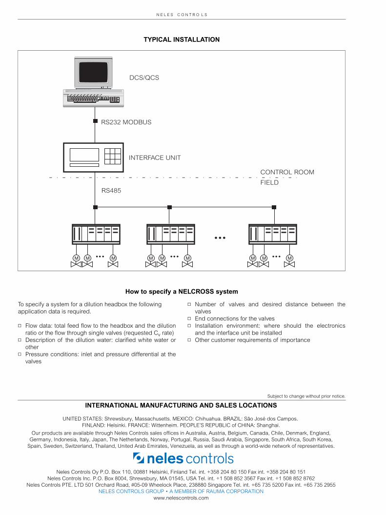
TYPICAL INSTALLATION
To specify a system for a dilution headbox the followingapplication data is required.
▫
Flow data: total feed flow to the headbox and the dilutionratio or the flow through single valves (requested C
v
rate)
▫
Description of the dilution water: clarified white water orother
▫
Pressure conditions: inlet and pressure differential at thevalves
▫
Number of valves and desired distance between thevalves
▫
End connections for the valves
▫
Installation environment: where should the electronicsand the interface unit be installed
▫
Other customer requirements of importance
INTERFACE UNIT
DCS/QCS
RS232 MODBUS
RS485
CONTROL ROOM
FIELD
How to specify a NELCROSS system