8 0 F E DO IT YOURSELF SERIES Booklet Number 2 IT YOURSELF SERIES Booklet Number 2 FERROIEmEnT...
41
2 1.7 8 0 F E D O IT YOURSELF SERIES Booklet Number 2 CT3 rn 0 L_nJ $H mTERnnnonni FERROcEmErn inFORmnnon IEIITER z i^-Sbfe -S^e
Transcript of 8 0 F E DO IT YOURSELF SERIES Booklet Number 2 IT YOURSELF SERIES Booklet Number 2 FERROIEmEnT...
2 1 .7
8 0 F E D O IT YOURSELF SERIES Booklet Number 2
CT3
r n 0
L_nJ
$H
mTERnnnonni FERROcEmErn inFORmnnon IEIITER
z i -Sbfe -S^e
INTERNATIONAL FERROCEMENT INFORMATION CENTER (IFIC) STAFF
Director : Dr. J. Vails (France) Associate Director : Dr. R. P. Pama (Philippines)
Senior Information Scientist : Mr. V.S. Gopalaratnam (India) Secretary : Ms. Lalida Vichitsombat (Thailand)
ACKNOWLEDGEMENTS
The IFIC gratefully acknowledges the financial support received from the United States Agency for International Development (USAID), the Government of New Zealand and the International Development Research Center (IDRC) of Canada. Thanks are also due to Ms. Arunee Boonyapukdi for typing the manuscript.
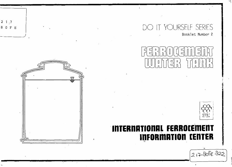
DO IT YOURSELF SERIES Booklet Number 2
FERROIEmEnT UIHTER TflllK P. C. Sharma and V S. Gopalaratnam
UBRARY. INTERNATIONAL R E ^ N C E y
CENTRE FOR COMMUNITY WATER SUPPLY AND SANITATION (IRC) PO Box 93190, 2&09 AD The Hague Tel. (070) 814911 ext, 141/142
LO: 21=7 SO rET
LIBRARY International Reference Centre for Community Water Supply
iniERiniTionnL PERROcEmEnT inFORmnnon CERTER
Ferrocement Water Tank
P.C. Sharma, Scientist, Structural Engineering Research Centre, Roorkee, India. V.S. Gopalaratnam, Senior Information Scientist, International Ferrocement Information Center, Bangkok, Thailand.
Copyright © 1980, by : International Ferrocement Information Center (IFIC) Asian Institute of Technology, P.O. Box 2754 Bangkok, Thailand
All rights reserved.
No part of this book may be reproduced by any means, stored in a retrieval system, or transmitted in any form or by any means, electronic, mechanical, photocopying, recording or otherwise, without the written permission of the publisher.
IFIC Publication No. 17/80, May 1980.
Price: US$2.00 (inclusive of postage by surface mail).
II
Foreword
The need for hygenic and economical water storage structures in the rural areas of the developing countries is urgent. Experiences accumulated in the recent past substantially prove that ferrocement is an ideal material for the construction of water tanks. With these facts in view IFIC decided to publish this booklet which it believes will be a useful contribution in alleviating the water storage problem in many remote villages.
Ferrocement Water Tank is the second booklet in the Do it yourself series published by IFIC. The present booklet benefits from several useful comments from reviewers and users of IFIC's first booklet in the series, on Ferrocement Grain Storage Bin. Clarity of drawings have been greatly improved by delinking it from the text (Part I — Instruction Manual ) and incorporating it into Part II entitled Get Down to do it.
We welcome comments and suggestions from users for further improvements of subsequent booklets in this series. Drafts of two more booklets in this series, booklet 3 on Ferrocement Biogas Holder and booklet 4 on Ferrocement 'Canoe are under preparation.
We sincerely hope this series of Do it yourself booklets will be found useful in promoting ferrocement applications.
The Director
Ml
Instruction manual Port I
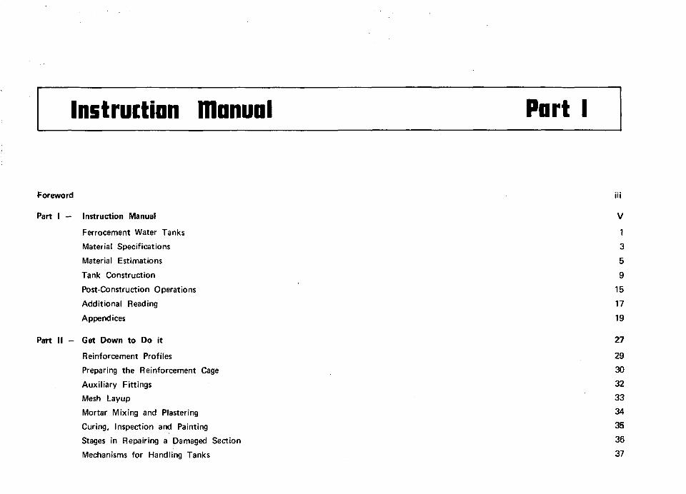
Foreword iii
Part I — Instruction Manual V
Ferrocement Water Tanks 1
Material Specifications 3
Material Estimations 5
Tank Construction 9
Post-Construction Operations 15
Additional Reading 17
Appendices 19
Part II - Get Down to Do it 27
Reinforcement Profiles 29
Preparing the Reinforcement Cage 30
Auxiliary Fittings 32
Mesh Layup 33
Mortar Mixing and Plastering 34
Curing, Inspection and Painting 35
Stages in Repairing a Damaged Section 36
Mechanisms for Handling Tanks 37

Ferroiement Water Tanks 1
Introduction
Problems related to water storage and supply are of increasing concern in most parts of the developing countries. Although water itself might not be a scarce resource in the urban centers, its supply to highly decentralized rural population is neither simple nor economical. Most of such areas have consequently been attracted to collect and store rain water or water from other sources. Although unhygenic storage results in the spread of waterborne diseases,the vast majority of the rural population, find more scientific non-traditional storage structures beyond their reach.
Among the non-traditional storage structures that are presently used are tanks made of reinforced concrete, steel, galvanized iron and asbestos cement. Reinforced concrete tanks require the use of expensive formwork (especially for cylindrical tanks) and skilled labor. They are quite heavy and consequently when used as overhead tanks, require stronger supporting structure. Metal tanks require sophisticated equipments for fabrication, provide poor thermal insulation and their service life even with regular maintenance is short. Raw materials have in most cases to be imported. Asbestos tanks are brittle and as a result are susceptable to frequent damages. Additionally, recent studies have shown that asbestos fibers are hazardous to health. Besides all these drawbacks, all of the tanks discussed above are relatively expensive.
As a comparison, traditional storage structures though economical are not durable, nor are they hygenic. Storage structures of this type are made of raw, fibrous or baked clay and are generally unlined. In most cases their storage capacities are also far from adequate.
Experiences accumulated over the past decade have proven that ferrocement water tanks offer a more economical storage alternative,
without in any way, compromising on the quality, as when compared to earlier listed storage structures.
Ferrocement
Ferrocement is a highly versatile form of reinforced mortar in which closely spaced and evenly distributed wire mesh reinforcement, is impregnated with a rich cement-sand mix. This technique allows for fabrication of complex shapes as thin as 1 cm, even without the use of formwork. It has a high strength to weight ratio when compared to reinforced concrete, requires little or no maintenance when compared to metal structures and is more durable than asbestos. The following section highlights specific advantages of ferrocement for the construction of water tanks.
2
Water tanks of ferrocement
In most situations, ferrocement water tanks are less expensive than reinforced concrete, metal or even asbestos tanks. However, before deciding to build a water tank of ferrocement, it is advisable to compare the total costs (material, labor, transportation, installation and maintenance), based on relevant local estimates. The following advantages of ferrocement can be realized using proper construction techniques.
(i) Compatible strength for a much reduced self-weight, as when compared to reinforced concrete.
(ii) A more durable and hygenic storage requiring less frequent maintenance as when compared to metal tanks.
(iii) High resistance to cracking even under adverse thermal stresses that exist during service.
(iv) Availibility of all raw materials required for construction. The fact that ferrocement construction does not require the use of any heavy machinery is particularly suited to the rural areas of the developing countries.
(v) In case of accidental damages to such tanks, one could easily repair it at site, saving both time and money. Repair at site is difficult, if not impossible for tanks made from other materials.
Performance evaluation of ferrocement water tanks
Results obtained from laboratory structural tests, simulating service conditions, at the Asian Institute of Technology, Bangkok, (Thailand), Structural Engineering Research Center, Roorkee and Madras (India), University of Singapore (Singapore), University of Illinois (U.S.A.) and New Zealand Portland Cement Association, Wellington (New Zealand) adequately highlight the superb performance and durability of such tanks. Factory production and sales of ferrocement tanks of various capacities, in New Zealand (200 to 5,000 gallons) and India (20 to 2000 gallons) and their successful field performance over the years, substantiate results obtained from laboratory studies. Large numbers of ferrocement tanks have also been constructed at sites in Bangladesh, Indonesia, Malaysia, Thailand and the U.S.A.
Appendix I gives details of a more recent semi-mechanized process for casting cylindrical ferrocement elements, that can effectively be adopted for manufacture of water tanks. This process developed by the Structural Engineering Research Centre, Roorkee, is presently being used to manufacture water tanks on a commercial scale. Note however that for the design discussed in this booklet this technique is not readily adaptable.
material Specifications
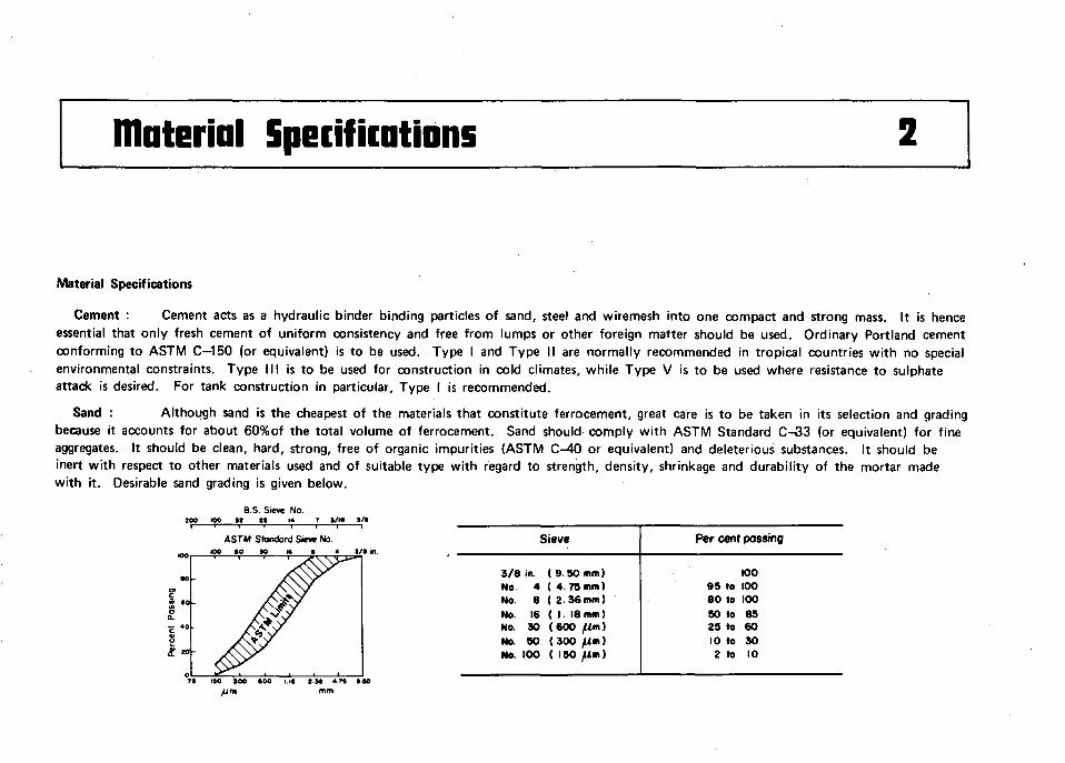
Material Specifications
Cement : Cement acts as a hydraulic binder binding particles of sand, steel and wiremesh into one compact and strong mass. It is hence essential that only fresh cement of uniform consistency and free from lumps or other foreign matter should be used. Ordinary Portland cement conforming to ASTM C—150 (or equivalent) is to be used. Type I and Type II are normally recommended in tropical countries with no special environmental constraints. Type III is to be used for construction in cold climates, while Type V is to be used where resistance to sulphate attack is desired. For tank construction in particular. Type I is recommended.
Sand : Although sand is the cheapest of the materials that constitute ferrocement, great care is to be taken in its selection and grading because it accounts for about 60%of the total volume of ferrocement. Sand should comply with ASTM Standard C-33 (or equivalent) for fine aggregates. It should be clean, hard, strong, free of organic impurities (ASTM C-40 or equivalent) and deleterious substances. It should be inert with respect to other materials used and of suitable type with regard to strength, density, shrinkage and durability of the mortar made with it. Desirable sand grading is given below.
B.S- Sieve No.
ASTM Standard Sieve No too to
Sieve
3/8 in. ( 9 50 mm) No. 4 ( 4. 75 nun) No. 8 ( 2 36mm) No. 16 ( 1. 18 nun) No. 30 (600 fim) No. 90 (300 flm) No. 100 ( ISO / i n )
Per cent passing
100 95 to 100 80 to 100 50 to 85 25 to 60 10 to SO 2 to 10
I M 4.79 ISO mm

Aggregate : Coarse aggregate for concrete used for construction of the water tank base should be well graded w i th a maximum size of
10 mm. crushed gravel, strong and non-porous, and should be free f rom silt or organic matter.
Water : Water used for mixing and curing is to be fresh and free f rom organic impurities and harmful chemical substances which lead to
a deterioration in the properties of mortar. Use of sea water is to be avoided. Potable water is f i t for use as mixing water as well as for
curing ferrocement structures.
Wire mesh : Several types of wire meshes are available: hexagonal wire mesh, welded or woven square mesh, expanded metal mesh and
Watson mesh. It has been observed that galvanized square (woven) mesh performs the best. The mesh should be clean and free f rom all loose
mill scale, dust, rust and coatings, such as paint, oil or anything that might reduce bond. The woven square mesh shall conform to ASTM
Standard A—185 (or equivalent) w i th a wire diameter of around 1.3 mm (18 gage) and spacing of around 12 mm VA in.).
Skeletal steel : Steel bars are used for making a frame of the structure over which the mesh is placed. Use of 6, 8 or 10 mm bars is
recommended depending upon the size of the water tank. The surface of these bars should be total ly free f rom greese, o i l , rust,
detergents and other organic matters. A simple field test could be conducted thus; bend the bar into an U shape and then straighten it out .
Bend it again into an U and on straightening if no cracks appear at the bend, then the bar is acceptable. They should conform to ASTM
A - 6 1 5 and ASTM A - 6 1 6 (or equivalent).
Binding (tying) wire : For ty ing the mesh layers on to the skeletal steel use of annealed (soft) galvanised wires of 24 or 26 gage is
recommended. However, cut pieces of wires f rom the meshes could also be used for typing.
Water proofing chemicals : It has been observed that addit ion of water proofing compounds in mortar for water tanks, improves its
properties. Special considerations shall be given to the use of additives in cement mortar for special purposes and shall comply w i th approved
standards if any, or should be based on actual performance tests.
Coatings : Coating is not required on the external surface of ferrocement water tank although it is recommended for aesthetic purposes only. Two coats of any cold fast-setting bituminous paint are to be applied on the exterior, if desired, after the tank has been cured tested and dried. Two coats of any standard non-toxic water tank paint are recommended for the interior (normally these are marketted as " Tankmast ic" or " Drinking Water" tank paint). This helps f i l l in any hairline surface cracks besides retarding algae growth. The paints used should be stable and durable for up to a specified temperature and pressure as well as chemically inert for the type of water stored. Use of bituminous alumunium paint (paint grade aluminium powder added to bituminous paint) is suggested for the external surface as it is aesthetic, economical and serves to reflect heat.
material Estimations 3
Selection of shape and size
The versatility of ferrocement enables one to construct water tanks of almost any conceivable shape. However, the most popular cross-sections for tanks are circular and rectangular. Most often the selection of the shape and size is governed by the storage capacity required, availibility of installation space and the location itself. Cylindrical ferrocement tanks (circular cross-section) have numerous advantages over rectangular ferrocement tanks in that they consume less material (consequently more economical) for the same storage capacity, have fewer sharp edges (which normally contribute to stress concentrations as well as construction and maintenance bottlenecks) and are aesthetically more pleasant. The following sections of this chapter and subsequent chapters discuss in detail the various aspects of construction of cylindrical tanks. Appendix II gives dimensional and reinforcement details of cylindrical ferrocement water tanks of various capacities (600 liters to 10,000 liters) in a convenient tabular form. 600 - 1200 liter tanks are suitable for individual dwellings while tanks of larger capacities are recommended for farms, schools, public buildings and other community centers. In Appendix III a sample estimation is included for a 1200 liter capacity water tank.
Once the storage capacity is estimated, the actual dimensions can be determined from the table in Appendix II. In case one desires to construct a tank of capacity other than those listed in the Table, it is recommended that a diameter-height ratio (d/h) of between 0.5 and 2.0 be maintained. A free board of 8-10 cm is provided to enable installation of a float-valve assembly (specially useful if the storage tank is directly connected to the water mains).
Material estimations
The following notations are used in computing the quantities of the various materials required for the construction of a ferrocement water tank.
A
Aco = A r = d Lb =
Total area of mesh required, (rr>2) Total surface area to be coated, exterior or interior (m^) Surface area of roof, outside or inside, (m2) Inside diameter of the water tank, (m) Total length of bars required for base reinforcement, (m)
Ab A| A w
h L|
= = = = =
Area of base, (m2) Surface area of lid, outside or inside, (m^) Surface area of vertical wall, outside or inside, (m2) Height of the wall upto overflow level, (m) Total length of bars required for the lid reinforcement, (m)
6
Total length of bars required for ring reinforcement in the roof, (m) Total length of bars required for ring reinforcement in the wall, (m) Thickness of the base, (m) Thickness of the roof, (m) Volume of coating required for the exterior, (Lit.) Volume of mortar required, (m3) Total weight of steel required, (kg) Weight of cement required, (kg) Weight of water required, (kg)
(1)
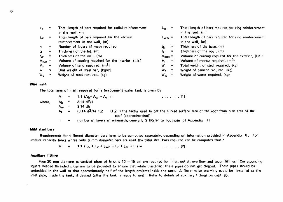
roof (approximation)) n = number of layers of wiremesh, generally 2 (Refer to footnote of Appendix I I)
Mild steel bars
Requirements for different diameter bars have to be computed seperately, depending on information provided in Appendix I I . For smaller capacity tanks where only 6 mm diameter bars are used the total steel bars required can be computed thus :
W = 1.1 (L b + L V + L w n + L r + L r r +L|) w (2)
Auxiliary fittings
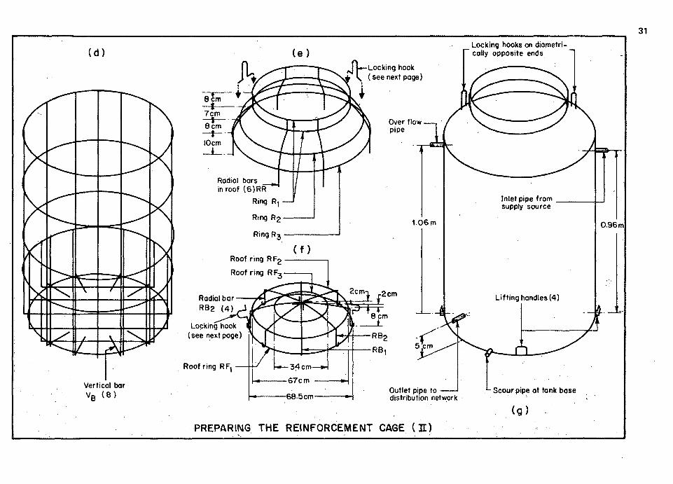
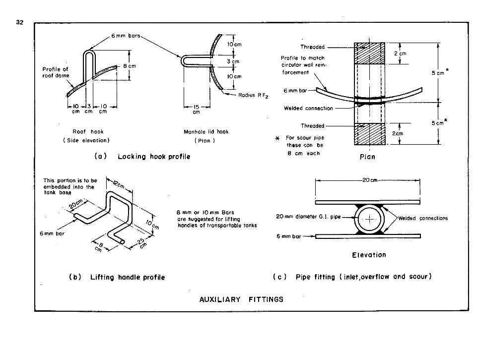
Four 20 mm diameter galvanized pipes of lengths 10 —15 cm are required for inlet, outlet, overflow and scour fittings. Corresponding square headed threaded plugs are to be provided to ensure that while plastering, these pipes do not get clogged. These pipes should be embedded in the wall so that approximately half of the length projects inside the tank. A float- valve assembly could be installed at the inlet pipe, inside the tank, if desired (after the tank is ready to use). Refer to details of auxiliary fittings on page 30.
Lr
Lv
n
t|
tw
Vico Vs
w
Ws
Wire mesh
—
=
= = = = = = =
The total
where,
Total length of bars required for radial reinforcement in the roof, (m) Total length of bars required for the vertical reinforcement in the wall, (m) Number of layers of mesh required Thickness of the lid, (m) Thickness of the wall, (m) Volume of coating required for the interior, (Lit.) Volume of sand required, (m^) Unit weight of steel bar, (kg/m) Weight of sand required, (kg)
area of mesh required for a ferrocement water tank is
A = 1.1 (AD+ A w + A r) n
Ab = 3.14 d2/4 A w = 3.14 dh Ar = (3.14 d2/4) 1.2 (1.2 is the factor used
Lrr =
Lwn =
tb = tr =
Veco =
V m = W Wc =
Ww =
given by
to get the curved i
7
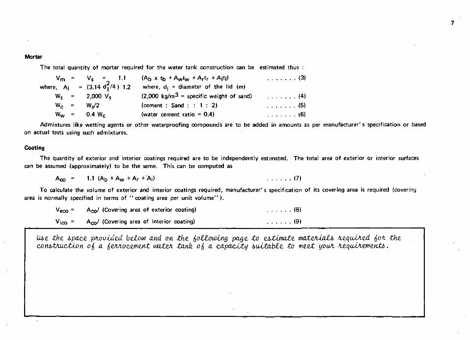
Mortar
The total quantity of mortar required for the water tank construction can be estimated thus :
V m = Vs = 1.1 (Ab x t b + A w t w + A r t r + A|t|) (3) 2
where, A| = (3.14 d j / 4 ) 1.2 where, d| = diameter of the lid (m)
Ws = 2,000 Vs (2,000 kg/m3 = specific weight of sand) (4)
Wc = Wj/2 (cement : Sand : : 1 : 2) (5)
Ww = 0.4 Wc (water cement ratio = 0.4) (6)
Admixtures like wetting agents or other waterproofing compounds are to be added in amounts as per manufacturer's specification or based on actual tests using such admixtures.
Coating
The quantity of exterior and interior coatings required are to be independently estimated. The total area of exterior or interior surfaces can be assumed (approximately) to be the same. This can be computed as
Aco = 1.1 (Ab + A W + A r +'A|) (7)
To calculate the volume of exterior and interior coatings required, manufacturer's specification of its covering area is required (covering area is normally specified in terms of "coating area per unit volume").
Veco = ACQ/ (Covering area of exterior coating) (8)
v ico = ACQ/ (Covering area of interior coating) (9)
tiae the. i>pace. pfiovidtd beZooo and on the. ^otiouotng paae, to estimate. mateAlati> h.e.quJjie.d ^ofi the. con6tAu.cJU.on o{ a ^eJViocement wateA tank oft a capacity MuXable. to me.eX. youA SLcquuAwe.nt!>.

8
lank Construction 4
Site selection
For water tank construction, selection of a proper site is of utmost importance. Functionally, it is necessary to select the highest point within the area it is expected to serve. This would facilitate supply to the entire service area (specially for community tanks) without the use of additional pumping devices. Besides, this would also provide for,a natural drainage of the site. In case such an arrangement is not possible due to site constraints, the tank could alternatively be mounted on supports at any desired elevation. Supports in such cases have to be designed so that there is an even distribution of load, by use of braces and ring beams connecting the columns at various levels. In some cases additional reinforcement for the water tank base might also have to be provided. Tank supports and foundations should be constructed on soils with adequate bearing capacity and not on uncompacted backfill.
For individual dwellings, the tanks could be mounted atop roofs or on any elevated platform, so that they meet all the functional and structural requirements desired.
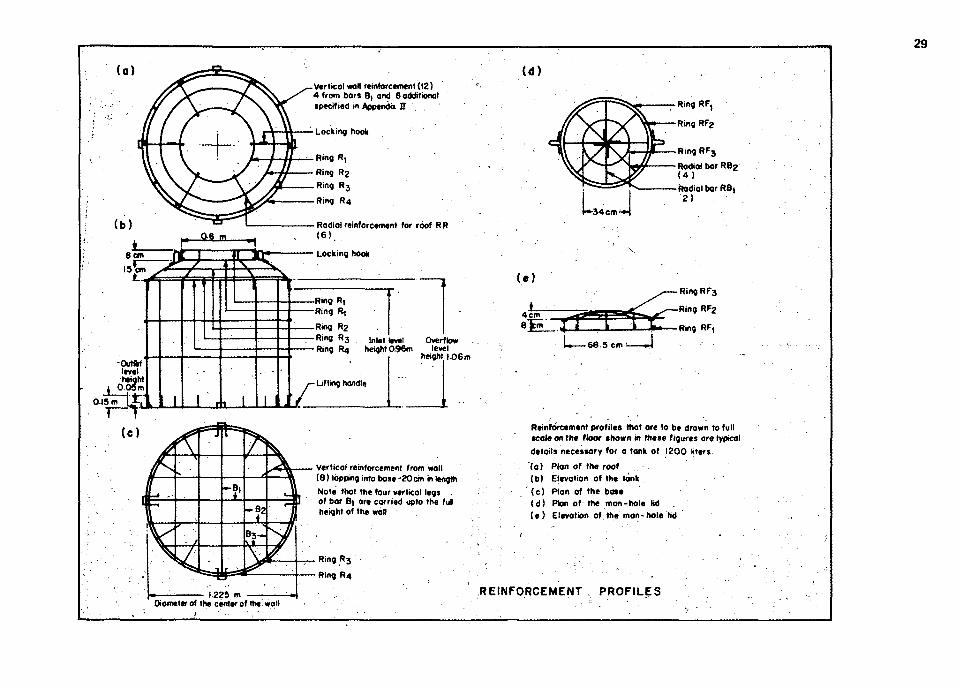
Drawing profiles on the floor
Tank reinforcement profiles drawn to a full scale on the floor, help a great deal while cutting and bending of steel bars that are used in fabricating the basic skeletal steel cage. Four drawings that would serve the purpose are :
(a) Plan of the roof reinforcement. (b) Elevation of the tank reinforcement cage. (c) Plan of the base reinforcement. (d) Plan and Elevation of manhole lid reinforcement.
These profiles also ensure accurate cutting and bending of steel bars besides helping in precise dimensional control.
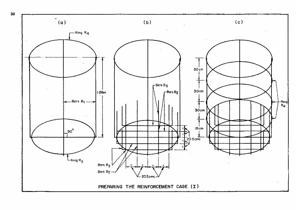
Preparing the skeletal steel cage
For identification of notations used for the various component bars of the cage refer to Part II of the booklet and the drawing

10
in Appendix I I I .
Once all the bars are cut to specified lengths and bent to proper profiles, these are to be welded or tied to each other in the sequence described in this section. In case welding facilities are not available.it is necessary to provide additional lengths of laps to ensure rigid connections between component bars. The two bars Bi are tied at right angles to each other and are held in position by Rings FU at the base level and R at the roof- wall joint level. Subsequently, other bars in the base as per the designed spacing are tied. Rings R4 are tied along the height of the wall in numbers specified in Appendix I I . Vertical wall reinforcement in addition to the vertical legs of B1, are tied to Rings R4. Inlet, outlet t overflow and scour pipe fittings are tied at the various wall levels specified. Cage for the roof is fabricated seperately based on the earlier drawn profiles. This is then fixed to the base-wall unit so that adequate lap is available between projecting vertical bars of the wall and radial bars of the roof. Ensure also that the manhole level height is maintained as per the design. Four equally spaced lifting hooks at the base are to be provided. Two locking hooks diametrically opposite to each other, adjacent to the manhole in the roof are to be provided. Reinforcement for the manhole lid is to be seperately prepared which is also to include locking hooks that match with the ones provided in the roof (for details refer Part II of the booklet)
Tying wire meshes
Unless otherwise specified in Appendix II ,use two layers of 18 - 20 gage galvanized square (woven or welded) mesh of 12 mm (Vi in.) mesh opening. One layer is to be tied on the inside of the skeletal steel frame and another on the outside using earlier specified tyjng wires. To ensure proper profile and compactness of reinforcements these mesh layers should be tied at 20 cm spacing along both the vertical and circumferential directions streching the meshes taut .Care should be taken to provide at least 10 cm overlap of meshes where these have to be joined. In case of roof - wall joint mesh layers should have laps of 10 cm each on the wall portion as well as the roof. Similar overlaps have to be provided for the wall - base joint. The two layers of mesh should be staggered in such a way that the effective opening size is reduced to half of the individual mesh opening. This misalignment provides for a more uniform distribution of reinforcement as well as a superior bond for the mortar while plastering.
Plastering
Before plastering can be undertaken, required quantities of mixed mortar and concrete (for type B only) should be prepared. The recommended mix proportions by weight are
cement : sand : water : : 1 : 2 : 0.4 (for types A &B) cement : sand : aggregate : water : 1 : 2 : 3 : 0.5 (for type B only)
Water proofing or other similar admixtures are to be thoroughly dry-mixed with cement and sand before water is added to the mix. Sand should be properly seived and void of all impurities as earlier specified. Mix the mortar in batches in such a manner that each batch of mixed mortar is plastered within an hour after mixing. This batching will reduce wastage of mortar caused as a result of partial setting.
11
Note however, that the consistency of the mortar mixes should be the same for all the batches.
Prior to plastering it should be ensured that the reinforcement cage is complete, including all auxiliary fittings like inlet, outlet, overflow and scour pipes, lifting handles and locking hooks. Bulge or slackness in wiremesh should be removed by readjusting the mesh by beating to the proper profile and tying them at more places to retain the desired shape.
The reinforcement cage is to be cleaned using a steel fiber brush to remove all loose scales on the cage. Construction procedures of the base for type A (in-situ) and for type B (transportable and mountable on columns) differ slightly, while they are similar for wall, roof and lid construction.
Type A : The ground is levelled after clearing grass and other plant growth from a circular area of diameter 75 cm greater than the designed diameter of the tank. Polyethylene sheet is to be spread over this area before a 2 cm thick layer of mortar is laid. This sheet besides preventing direct contact of wet mortar with soil, will provide an additional option of ease of shifting of the tank to another nearby location, if so desired at a later date. The reinforcement cage prepared earlier is to be placed over the wet mortar and moved so that the mortar layer penetrates into the bottom layer of mesh in the tank base and the cage gets an effective clear cover of 5 mm. Mortar can now be spread inside the tank base and levelled as per the designed thickness.
Type B : The base thickness for such bins have been increased for higher capacity tanks(as when compared to type A) so that they could withstand handling stresses, and stresses due to supports. The reinforcement cage for tanks of such type is exactly similar to that for type A with the only differencebeing,the mesh layer inside the base of the tank is cut at places, and temporarily rolled up the wall. As in type A, a 2 cm layer of wet mortar is laid over the polyethylene sheet. The reinforcement cage is placed over this and moved as in type A, to ensure proper penetration of the mortar into the base and at the same time maintain an effective clear cover of 5 mm for the bottom layer of mesh. Mortar is now spread inside the tank base to 'just cover' the base skeletal steel grid. A 2 cm layer of cement concrete (coarse aggregate also included in the mix, as mentioned earlier in this section) is laid next, after 16 to 20 tying wires are left projecting from the base skeletal steel grid. Mortar is plastered onto the wall upto a 5 cm height so that the wall-base joint is monolithic. The concrete surface in the base is roughened up with a steel fiber brush and left to harden for 24 hours. This roughening will aid adhesion of the subsequent layer of mortar to be placed later. After the concrete layer has hardened, the inside layer of mesh in the base that was earlier rolled up, is rolled down onto the concrete surface. The 16-20 tying wires that were earlier left projecting out of the concrete surface are used to tie down the inside base mesh. Cement slurry is brushed over the concrete layer before mortar is laid again. Mortar is now spread inside the tank base, providing a 5 mm cover to the inside layer of base mesh.
Common to both types : After completing the operations described earlier for the specific type of tank under construction, plastering of the wall can now begin. Plaster should be applied by a person (hereafter referred to, as mason) from the inside, pushing mortar onto the layers of meshes, with the assistance of another person (hereafter referred to, as helper) who is to hold a sheet of plywood or galvanized iron on the corresponding area, outside. Mortar application can be accomplished by either using the trowel or the hand. The helper is to shift the backing sheet of plywood or galvanized iron to the adjoining area when plastering is completed on the earlier region. The mason should ensure that mortar is well compacted and a 3 mm cover for the reinforcements is provided on finishing both the inside as well as the outside surfaces. It
12
is recommended that the roof be plastered after plastering the wall portion. Extra care is to be taken while plastering around the inlet, outlet, overflow and scour fittings. When the first application of mortar on both the roof and the wall have been completed, a coir brush is used to scrape off excessive mortar built up, as well as making the layer rough so as to improve adhesion of the finishing layer. The lid is also plastered seperately in a similar manner.
The water tank is to be left to dry for 24 hours before application of the finishing layer. Mortar used for finishing is proportioned in the same manner as earlier and applied over the earlier roughened inside and outside surfaces of the water tank. Final wall thickness of around 25 mm including a minimum cover of 3 mm on both the inside and outside is suggested. For the dome roof a thickness of 25 mm with the same minimum cover of 3 mm on both the top and the bottom surfaces (refer Appendix II for details of thickness) is recommended.
Curing
For any ferrocement structure, this is one of the most important stages. This is a stage when the mortar mix attains its strength. In the first two weeks the mortar nearly attains most of its designed strength, although a curing period of 28 days is suggested. Curing can start 24 hours after application of the finishing layer. Under normal conditions jute or hessian bags are soaked in water before they are used to cover the water tank. They are kept moist at all times during the curing period with regular spraying of water. Shrinkage cracks could appear on the surface of thin ferrocement structures if curing is improper. During the first 24 hrs after plastering the surface should not be permitted to dry. In case a dry patch is observed, a very fine spray of water is to be used to keep the freshly plastered surface moist.
Inspection,testing and repairing
After proper curing, the water tank is to be tested by filling it with water. Details of this stage are presented in the next chapter, which also includes procedure for repairing localized damages or cracks.
Painting and erection
Once the water tank has been successfully tested, painting operations can be carried out after drying the water tank for a week . In case any repair is carried out after testing, the water tank is to be dried for a further period as necessary before painting can be undertaken. Details of painting and erection are presented in the next chapter.
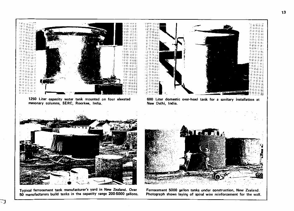
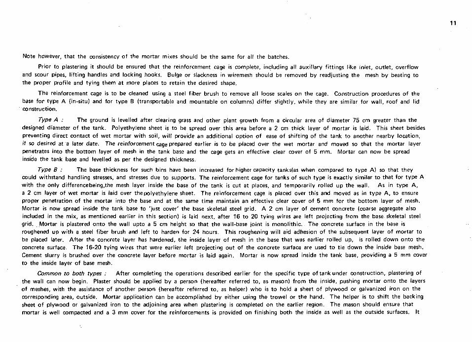
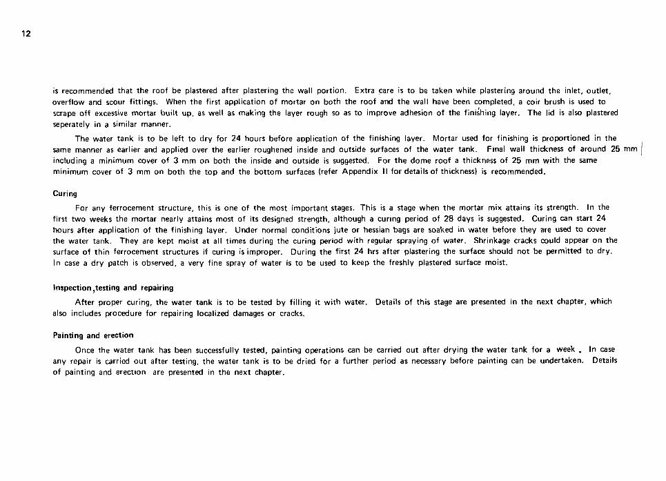
1250 Liter capacity water tank mounted on four elevated masonary columns, SERC, Roorkee, India.
600 Liter domestic over-head tank for a sanitary installation at New Delhi, India.
Typical ferrocement tank manufacturer's yard in New Zealand. Over 50 manufacturers build tanks in the capacity range 200-5000 gallons.
Ferrocement 5000 gallon tanks under construction. New Zealand. Photograph shows laying of spiral wire reinforcement for the wall.

14
Plastering the man-hole of a-2000 liter water tank, Asian Institute of Technology, Bangkok, Thailand.
The completed 9000 liter rectangular tank, supported by three inverted U frames. University of Singapore.
flSH^T^
The armature of a-9000 liter rectangular tank showing reinforcing details is ready for plastering. University of Singapore.
Experimental set-up to measure strain and thus determine maximum bending stress in service. University of Singapore.
Post-Construction Operations 5
Among the post-construction operations to be carried out are :
Testing Repairing (if necessary) Drying and Painting Installation
Testing
After curing operations have been completed ferrocement water tanks have to be tested, before painting can be undertaken. The inlet, outlet, overflow and scour fittings are temporarily sealed with plugs and commonly used plumbing sealant (fibrous white lead paste). Water is filled upto the brim of the tank and exterior surfaces are observed after retaining water for a day. Cracks, pinholes and damp patches are located if any, and repair carrried out accordingly.
Repairing
Ferrocement water tanks do not require regular maintenance like metal or masonary tanks. In case poorly constructed areas are identified while testing, or the tank has been accidentally damaged during installation, it can be repaired without much difficulty. Small damp patches that occur while testing could be repaired by applying 2 coats of interior and exterior paints as described in the next section. Small hairline cracks and pinholes could be filled up using a rich cement: sand paste (1 : 1 by weight) after roughening the crack or pinhole location to ensure proper adhesion. For larger cracks or localized damage, the following procedure for repair is suggested :
1. Mortar in and around the damaged area is chipped off using a fine round head chisel and a small hammer exposing all reinforcement. Mortar in the adjoining area is chipped upto levels where the inside and outside wiremesh layers are exposed. Reinforcement in the affected area is straightened and profiled if necessary.
16
2. The adjoining area of chipped mortar is coated with a rich cement slurry using a cement brush.
3. The damaged area is now ready for replastering following the procedure described earlier in plastering.
4. The replastered area is to be cured for 3 - 4 days before the tank can be put to use. It should be retested before painting.
Drying and painting
After successful testing, the tank is dried for 3 - 4 days (avoid direct sunlight). Interior and exterior surfaces are brushed to ensure that loose particles or dust are removed, two coats of interior and exterior paints are applied, as earlier specified. One coat of paint with vertical strokes is applied followed by a second coat with horizontal strokes. It is necessary to allow for a 2 - 4 hour drying period between the two coats, or as specified by the paint manufacturer. Care should be taken to adquately fi l l all hairline surface cracks, pinholes and other minor defects with paint.
Installation
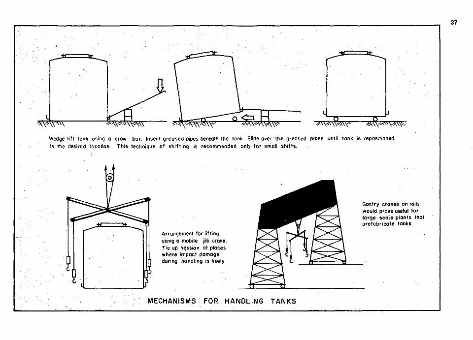
Ferrocement water tanks should be lifted to place using only the 4 lifting hooks provided in the base of the tank. Specially designed tripods or small jib cranes and pulley-winch mechanisms could prove to be a big help, specially for large scale production. Tanks should at all times be in an upright position while transporting, handling or in service. For small shifts, wedge lifting the tanks and sliding them on greased pipes has been observed to be efficient.
Once the tank is in place, all auxilliary fittings can be unplugged (except scour) and connected to supply and distribution lines as desired. Locking facility of the lid to roof could be used if desired.

Additional Rending 6
1. GUERRA, A.J. , N A A M A N , A.E. and SHAH, S.P., 'Ferrocement Cylindrical Tanks : Cracking and Leakage Behaviour', ACI Journal, Proceedings, Vo l . 75, No. 1, January 1978, pp. 22 - 30.
2. GOPALAKRISHNAN, S., SHARMA, P.C. and R A M A N , N.V., "Small Capacity Ferrocement Water Tanks" , Proceedings of the 8th Session of the IASS Committee of Pipes and Tanks, Budapest, Hungary, June 1978, 8 pp.
3. NATIONAL ACADEMY OF SCIENCES, 'Ferrocement : Appl icat ion in Developing Countries', A Report of an ad hoc panel of the Advisory Committee of Technological Innovation, BOSTID, Washington, D.C., February 1973, 90 pp.
4. PARAMASIVAM, P., N A T H A N , G.K. and LEE, S.L., 'Application of Ferrocement Water Tanks (Phase I and I I ) , Prepared by. Faculty of Engineering, University of Singapore, for the Ministry of Science and Technology, Singapore, (1976, 64 pp.) and (1977, 69 pp.) respectively.
5. SURYA KUMAR, G.V. ,SHARMA, P.C, GOPALAKRISHNAN, S. and R A M A N , N.V., 'Casting Techniques for Ferrocement Cylindrical Units', Presented at the A l l India Seminar on Developments in Construction Technology, The Insti tut ion of Engineers (India), Bombay, December 1975, 12 pp.
6. WATT, S.B., 'Ferrocement Water Tanks and Their Construction', Published by Intermediate Technology Publications Limi ted, 1978, 118 pp.
Appendices
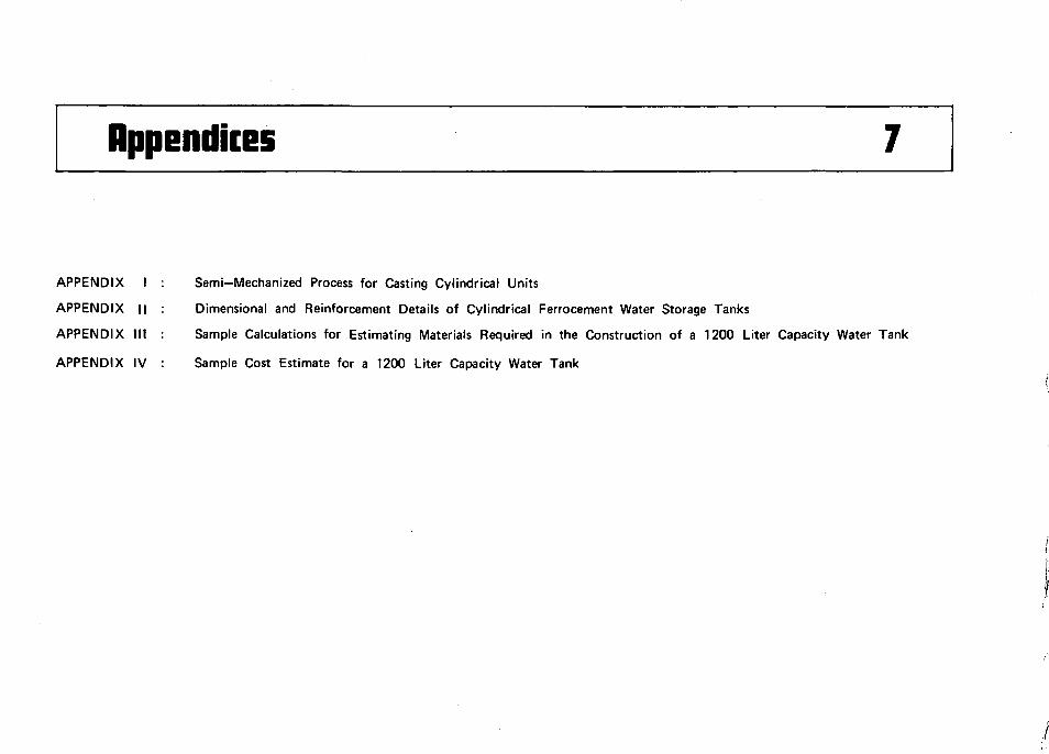
APPENDIX I
APPENDIX ||
APPENDIX III
APPENDIX IV
Semi—Mechanized Process for Casting Cylindrical Units
Dimensional and Reinforcement Details of Cylindrical Ferrocement Water Storage Tanks
Sample Calculations for Estimating Materials Required in the Construction of a 1200 Liter Capacity Water Tank
Sample Cost Estimate for a 1200 Liter Capacity Water Tank
APPENDIX I
Semi-Mechanized Process for Casting Cylindrical Units
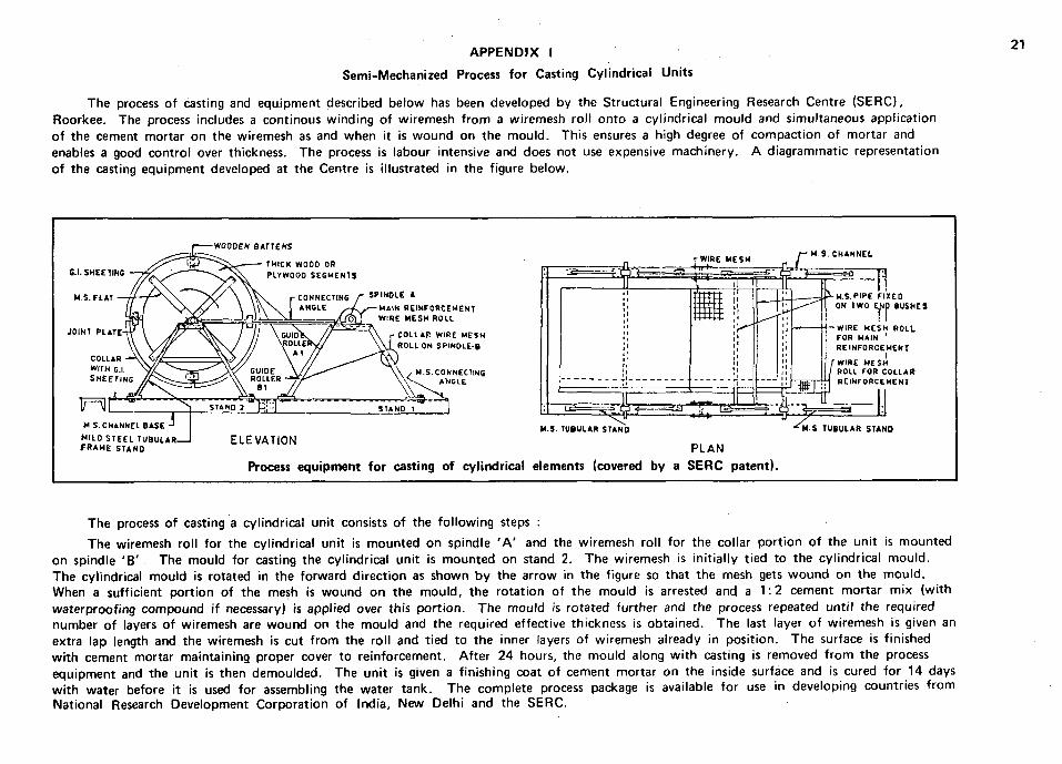
The process of casting and equipment described below has been developed by the Structural Engineering Research Centre (SERC), Roorkee. The process includes a continous winding of wiremesh from a wiremesh roll onto a cylindrical mould and simultaneous application of the cement mortar on the wiremesh as and when it is wound on the mould. This ensures a high degree of compaction of mortar and enables a good control over thickness. The process is labour intensive and does not use expensive machinery. A diagrammatic representation of the casting equipment developed at the Centre is illustrated in the figure below.
The process of casting a cylindrical unit consists of the following steps :
The wiremesh roll for the cylindrical unit is mounted on spindle 'A ' and the wiremesh roll for the collar portion of the unit is mounted on spindle 'B ' The mould for casting the cylindrical unit is mounted on stand 2. The wiremesh is initially tied to the cylindrical mould. The cylindrical mould is rotated in the forward direction as shown by the arrow in the figure so that the mesh gets wound on the mould. When a sufficient portion of the mesh is wound on the mould, the rotation of the mould is arrested and a 1:2 cement mortar mix (with waterproofing compound if necessary) is applied over this portion. The mould is rotated further and the process repeated until the required number of layers of wiremesh are wound on the mould and the required effective thickness is obtained. The last layer of wiremesh is given an extra lap length and the wiremesh is cut from the roll and tied to the inner layers of wiremesh already in position. The surface is finished with cement mortar maintaining proper cover to reinforcement. After 24 hours, the mould along with casting is removed from the process equipment and the unit is then demoulded. The unit is given a finishing coat of cement mortar on the inside surface and is cured for 14 days with water before it is used for assembling the water tank. The complete process package is available for use in developing countries from National Research Development Corporation of India, New Delhi and the SERC.
22
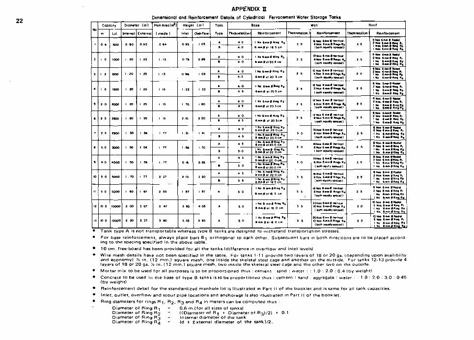
APPENDIX H Dimensional and Reinforcement Details of Cylindrical Ferrocement Water Storage Tanks
No
'
2
3
4
5
ft
7
8
8
K>
'•
12
13
Capacity
m.
0 6
I 0
1 . 2
1 5
2 0
2 3
2 3
3 0
4 0
5 0
3 0
10 0
K> 0
L i t
6 0 0
1000
woo
1900
2 0 0 0
2300
2 8 0 0
3 0 0 0
* O O 0
SOOO
3 0 0 0
I0OOO
10000
Diameter (m)
Internal
0 9 0
1 . 2 0
1 - 2 0
l 20
1 20
1 20
1 -SO
1 90
1 3 0
1 - 7 0
1 - 8 0
2 - 0 0
2 - 2 0
Externol
0 9 3
1 23
1 . 2 3
1 29
1 23
1 29
1 3ft
1 9ft
1 3ft
1 77
1 87
2 0 7
2 27
PlonArtotm2)
(insidt )
0 6 4
1 -13
1 -13
1 13
1 13
1 13
1 . 7 7
1 77
1 77
2 - 2 7
2 33
2 4 7
3 SO
H e i g h t ( i n )
Inlet
0 9 3
0 7 9
0 9ft
1 - 2 3
1 7 0
2-10
1 31
1 6«
2 1 f t
2 .10
1 -87
3 8 9
2 S3
Overflow
1-03
0 8 9
1 0 6
1 33
I 8 0
2 - 2 0
1 41
1 70
2 - 2 6
2 20
1 97
4 - 0 3
2 63
Tonk
Type
A
B
A
B
A
B
A
B
A
8
A
B
A
B
A
B
A
8
A
B
A
A
A
Base
Thickness (cm!
4 0
4 . 0
4 0
4 0
4 0
4 3
4 0
4 6
4 0
4 3
4 0
4 3
4 0
4 3
4 3
3 0
4 5
3 0
4 3
3 3
3 0
3 0
3 0
Reinforcement
1 No ftmm0 Ring R j
6 mm 0 of 18 5 cm
t No 6mm 0 Ring R,
ft • • 0 at 2 0 3 cm
INo.f tmm0R>ng R»
ftnwnfl at 20 3 cm
1 Ho 6 m m 0 f t m g R»
6 m m 0 ot 2 0 3 cm
1 No 6 m m 0 R*g R i
6 m m 0 oi 20 3cm
1 Ho 6 m m 0 Ring R»
6 mm 0 at 20 3 cm
1 No 6 m m 0 Ring R j 6 mm0 ot 2 0 0 cm
1 No. 6 mm 0 Ring R» 8 m « 0 a t 20 O c m
1 Ho 6 mm 0 Ring R» 6 m m 0 at 20 0 cm
1 No. 6 m m 0 Ring R | 8 mm 0 o t 2 O Ocm
I No 6 m m 0 Ring R | 6 m m 0 o t 2 0 0 c*» 1 No 6 m m 0 Ring R | 8 m m 0 o t 20 0 cm
1 Ho 6 m m 0 Ring R j 8 mm0 ot 22 0 cm
1 No 6 mm 0 Ring R i 8 mm0 at 18 5 cw
1 No 8 m m 0 R i n g f l B
8 mm0 at 18 3 em
1 No 8 mm 0 Ring R»
8 m m f l o t 18.0 cm
I No 8 mm 0 Ring R ,
8 mm flat 16 O c m
T h c k n e s s l c m )
2. s
2 3
2 3
2 3
2 3
2 3
3 0
3 0
3 0
3 3
•3 3
3 3
3 3
#all
Reinforcement
8 No* 6 * » » 0 Vtrtical 4 No* 6mm 0 Ring* R4
(both oouof ty tpocod)
l2Hot 6m«0v* r t f coJ 4 H o * 6 m m 0 R m g i R4
(both •ovoflj »poc*xJ)
i2No* 6 mm 0 Vtrtical 4 Ho* ft mm 0 Ring* R4
f froth *quoNy • m c t d )
B U M ftmm0 V«*ttcol 3 Ho* 8 OWN 0 Rtfig* R4
(both tgvaly • M c t a )
12 Ho* 6 mm 0 Vortical 6 No* 6 mm 0 Rmg* R^ [both touoty I t o c t d )
12 Ho* 6 m m 0 Vtrttcol 8 No* 6 mm 0 Rmgs R^ ( both omjOJh; *POcod 1
16No* 6 m m 0 Vortical 6 Ho* « « « 0 R i n g * R 4
(both equally *pocod)
16 No* 6m*>0 Vorhcol 8 Ho* 6 mm 0 Ring* R4
( both •QuoBy tpQctd)
16No* 6 m m 0 Vtrtfcol 8 No* 6 mm0 Ring* R 4
(both tguliy t o o t t a )
16 No* 6 m m 0 Vttticol 8 No* 6 mm 0 Ring* R4
( botn touoly isocod )
(« Ho* 8 mm 0 Vorhcal 8No* 6 m m 0 Ring* R 4
(both tquoly spocod)
20No* ftmir.0, Votticai rONo* Bmmft Rmo* R 4
( both oauoly tsoetd)
20 No* 6 rump Vortical 10 Ho* 8mm0Ring* R 4
(both *quolr tpocod)
Roof
Thtcfcnesstcm 1
2 3
2 3
2 3
t 9
t 9
2 3
2 3
2 3
2 3
2 9
2 3
3 0
3 0
Rtinf or cement
6 No* 6mm 0 RoaNU 2 No* 6«w*>0R*g R, 1 No* 6mm0*m>f R« 1 Ho* 6 mm 0 Ring R»
6 H M 6mm0Ro«a l 2 No* 6mm0Ring R, 1 Ho 6mm0Rmg R» I Ho 6 mm fl Ring R t
6 Ho* 6 mr*0 RodBQl 2 No* 6mm0Rmg R, i No 6 m m 0 Ring R t 1 Ho 6m*n0 Ring R j
ft HO* 6mm0Rodta* 2 Ho* 6mm0N<ng R| 1 No t « n > l « M Rfl 1 No ftmm0 Rtag R»
6 No* 6mm0 RMtal t No* 8*Mn0 Rwg R| 1 No < m m 0 R i n g R 2 1 No 6 « * » 0 Ring R»
6 Ho* 6 m m 0 Radiol 2 HO* 6 m m 0 Rmg R, I No 6mm0 Ring Rs
\ Ho ft*M>>0 Rmg R»
• No* 6mm0Rodt t l 2 Not 6 mm 0 Ring R, 1 No t mm*Ring R t 1 No 6 * M 0 R * * g R ,
8 No* 6 mm 0 RodW 2 Not ft mm 0 Mng R, 1 No ft mm 0 Ring R j 1 No 8 mm0Rm« R*
• Ho*. 6 mm 0 ROOM 2 No* 6 mm 0Rmg R| \ No 6fr.wi9JRmo.R2 1 No 6 mm 0 Ring R i
8 Ho* 6mm 0 Radial 2 No* 6 mm 0Rmg R, 1 Ho 6mm 0Rlng Rt 1 Ho ftmm 0Rmg R j
8 No* 8 mm 0 Radiol 2 No* 6 mm 0 Ring Ri 1 No 8 mm 0Ring « J I No 8 mm 0Ring R i
K) Ho* 8mm0Ro9Ol 2 Ho* 8 mm 0Rmg Ri 1 Ho 8 mm flRtng R t 1 No 8 mm 0Ring R j
K> Hot 8 mm 0Ro61ol 2 Ho* 8 mm 0 Rmg Ri 1 Ho 6mm flRtng R» I No 8 mm 0 Ring R i
Tank type A is not transportable whereas type B tanks are designed to withstand transportation stresses. For base reinforcement, always place bars B-j orthogonal to each other. Subsequent bars in both directions are to be placed according to the spacing specified in the above table.
1 0 crn. free-board has been provided for all the tanks (difference in overflow and inlet levels). Wire mesh details have not been specified in the table. For tanks 1-11 provide two layers of 18 or 20 ga. (depending upon availibiity and economy) Va in. (12 mm.) square mesh, one inside the skeletal steel cage and another on the outside. For tanks 12-13 provide 4 layers of 18 or 20 ga. Vi in. (12 mm.) square mesh, two inside the skeletal steel cage and the other two on the outside. Mortar mix to be used for all purposes is to be proportioned thus : cement : sand : water ; : 1.0 : 2.0 : 0.4 (by weight) Concrete to be used in the base of type B tanks is to be proportioned thus : cement : sand : aggregate : water : : 1.0 : 2.0 : 3.0 : 0.45 (by weight)
Reinforcement detail for the standardized manhole lid is illustrated in Part II of the booklet and is same for all tank capacities. Inlet, outlet, overflow and scour pipe locations and anchorage is also illustrated in Part 11 of the booklet. Ring diameters for rings R-}, R2, R3 and R4 in meters can be computed thus :
Diameter of Ring R1 = 0.6 m (for all sizes of tanks) Diameter of Ring R2 = ((Diameter of R^ + Diameter of R3)/2) + 0.1 Diameter of Ring R3 = Internal diameter of the tank Diameter of Ring R4 = (d + External diameter of the tank) /2.
23
APPENDIX III
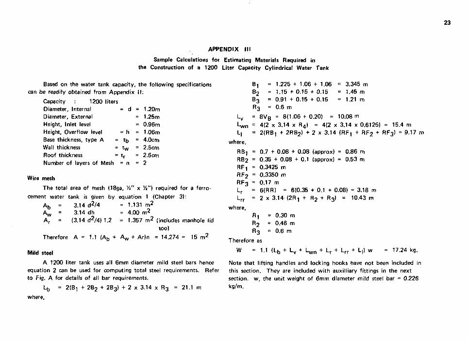
Sample Calculations for Estimating Materials Required in the Construction of a 1200 Liter Capacity Cylindrical Water Tank
Based on the water tank capacity, the following specifications can be readily obtained from Appendix I I :
Capacity 1200 liters Diameter, Internal = d = 1.20m Diameter, External = 1.25m Height, Inlet level = 0.96m Height, Overflow level = h = 1.06m Base thickness, type A = t b = 4.0cm Wall thickness = t w = 2.5cm Roof thickness = t r = 2.5cm Number of layers of Mesh = n = 2
Wire mesh
The total area of mesh (18ga, Va" x Vt") required for a ferro-
cement water tank is given by equation 1 (Chapter 3):
A b = 3.14 d2 /4 = 1.131 m 2
Aw = 3.14 dh = 4.00 m2
A r = (3.14 d2/4) 1,2 = 1.357 m 2 (includes manhole lid too)
Therefore A = 1.1 (Ab + A w + Ar)n = 14.274 = 15 m 2
Mild steel
A 1200 liter tank uses all 6mm diameter mild steel bars hence equation 2 can be used for computing total steel requirements. Refer to Fig. A for details of all bar requirements.
Lb = 2(B! + 2B2 + 2B3) + 2 x 3.14 x R3 = 21.1 m
where.
B, = 1.225 + 1 . 0 6 + 1 . 0 6 = 3.345 m B2 = 1.15 + 0.15 + 0.15 = 1.45 m B3 = 0.91 + 0.15 + 0.15 = 1.21 m
R3 = 0.6 m
Lv = 8VB = 8(1.06 + 0.20) = 10.08 m
C n = 4(2 x 3.14 x R4) = 4(2 x 3.14 x 0.6125) = 15.4 m
L| = 2(RB! + 2RB2) + 2 x 3.14 (RFT + RF2 + RF3) = 9.17 m
where,
RBi = 0.7 + 0.08 + 0.08 (approx) = 0.86 m RB2 = 0.35 + 0.08 + 0.1 (approx) = 0.53 m RF! = 0.3425 m RF2 = 0.3350 m RF3 = 0.17 m Lr = 6(RR) = 6(0.35 + 0.1 + 0.08) = 3.18 m L r r = 2 x 3.14-(2R.| + R2 + R3) = 10.43 m
where, R-) = 0.30 m R2 = 0.46 m R3 = 0.6 m
Therefore as
W 1.1 ( L b + L v + L w n + L r + L r r + L|) w = 17.24 kg.
Note that lifting handles and locking hooks have not been included in this section. They are included with auxilliary fittings in the next section, w, the unit weight of 6mm diameter mild steel bar = 0.226 kg/m.
24
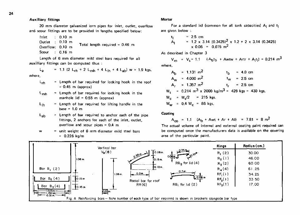
Total length required = 0.46 m
Auxiliary fittings
20 mm diameter galvanized iorn pipes for inlet, outlet, overflow
and scour f i tt ings are to be provided in lengths specified below.
Inlet : 0.10 m
Outlet : 0.10 m
Overflow: 0.10 m
Scour : 0.16 m
Length of 6 mm diameter mild steel bars required for all
auxil l iary f i tt ings can be computed thus :
La = 1.1 (2 L r h + 2 L m h + 4 L,h + 4 La b ) w = 1.9 kgs.
L r n = Length of bar required for locking hook in the roof
= 0.45 m (approx)
L m n = Length of bar required for locking hook in the
manhole lid = 0.55 m (approx)
L|n = Length of bar required for l ift ing handle in the base = 1.0 m
Lab = Length of bar required to anchor each of the pipe
fitt ings, 2 anchors for each of the inlet, out let,
overflow and scour pipes = 0.4 m
w = unit weight of 6 mm diameter mild steel bars
= 0.226 kg/m
where.
Mortar
For a standard lid (common for all tank capacities) A| and t|
are given below :
t| = 2.5 cm
A| = 1.2 x 3.14 (0.3425)2 x 1.2 + 2 x 3.14 (0.3425)
x 0.08 = 0.615 m 2
As described in Chapter 3
V
where. ' m V s = 1.1 ( A b t D + Awtw + Art r + A|t|) = 0.214 m 3
A b
A w
= 1.131 m 2
= 4.000 m 2
= 1.357 m 2
<b t w
Ws = 0.214 m 3 x 2000 kg/m 3 =
4.0 cm
2.5 cm
= 2.5 cm
428 kgs = 430 kgs.
W, Ws/2 = 215 kgs.
W w = 0.4 W c = 86 kgs.
Coating
*co = 1.1 ( A b + A w t + Ar + Al) = 7.81 = 8 m 2
The actual volume of internal and external coating paint required can
be computed once the manufacturers data is available on the covering
area of the particular paint.
Bar B. ( 2 )
| Bar B 2 ( 4 ) |
| Bor B 3 ( 4 ) | l.225m-1.150 m-0.91m
Vertical bar V B (6 )
1.06 m
O.I5m
O 16 m
_ _ . 0.08m.
0.16m. OOSmJ \JP
1 RB2 for lid (4) O.IOm.
1.06m. | - 0 3 B I , |
Radial bar for roof RR(6)
Q.7m.
RB, for lid (2 )
Rings
R, (2)
R 2 ( l ) R3 (2) R4 (4) RF, (1) RF2( 1) RF3( 1)
Radius (cm.)
30.00 46.00 60.00
61 .25
34.25 33 50 17.00
P2qm.
Fig. A Reinforcing bars— Note number of each type of bar required is shown in brackets alongside bar type
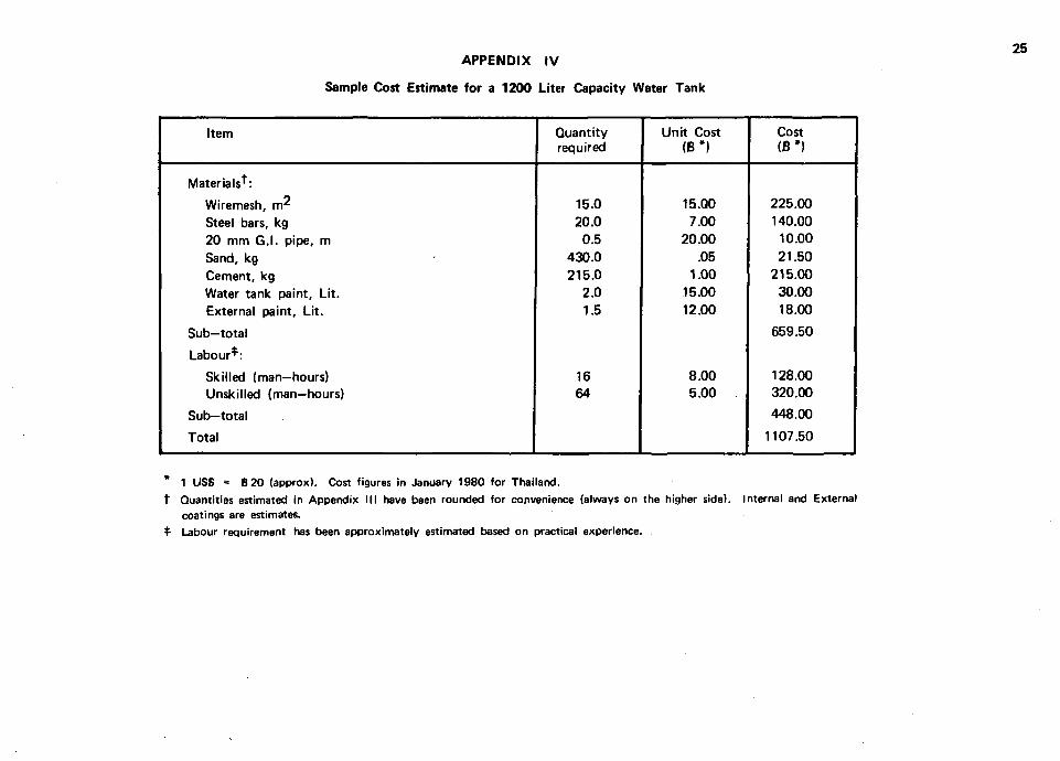
25 APPENDIX IV
Sample Cost Estimate for a 1200 Liter Capacity Water Tank
Item
Materials^:
Wiremesh, m* Steel bars, kg 20 mm G.I. pipe, m Sand, kg Cement, kg Water tank paint. Lit. External paint. Lit.
Sub-total
Labour*:
Skilled (man-hours) Unskilled (man-hours)
Sub-total
Total
Quantity required
15.0 20.0
0.5 430.0 215.0
2.0 1.5
16 64
Unit Cost (B#)
15.00 7.00
20.00 .05
1.00 15.00 12.00
8.00 5.00
Cost (B*)
225.00 140.00
10.00 21.50
215.00 30.00 18.00
659.50
128.00 320.00
448.00
1107.50
* 1 USS = 6 20 (approx). Cost figures in January 1980 for Thailand. t Quantities estimated in Appendix III have been rounded for convenience (always on the higher side). Internal and External
coatings are estimates. $• Labour requirement has been approximately estimated based on practical experience.
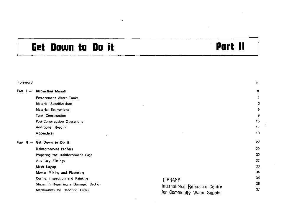
Get Down to Do it
Foreword
Part I — Instruction Manual
Ferrocement Water Tanks
Material Specifications
Material Estimations
Tank Construction
Post-Construction Operations
Additional Reading
Appendices
Part II — Get Down to Do it
Reinforcement Profiles
Preparing the Reinforcement Cage
Auxiliary Fittings
Mesh Layup
Mortar Mixing and Plastering
Curing, Inspection and Painting
Stages in Repairing a Damaged Section
Mechanisms for Handling Tanks
Part II
LIBRARY
International Reference Centre for Community Water Supply
in
v 1
3
5
9
15
17
19
27
29
30
32
33
34
35
36
37
OuMef level heiqht
OJ
mgl 005i
15 m jtj
Vertical wafl reinforcement (12) 4 from bars B, and 8 additional specified in Appendix H
Locking hook
-ftfijD-
••^a^s; Rodial reinforcement for roof RR
• < 6 ) .
Locking hook
-Ring R| -Ring R,
-Ring R2
-Ring R3 inlet level Overflow -Ring R4 height0.96m level
\L Lifting handle
height 1.06 m
(c)
- 1 22
~\
5 m
* ? 2
B 3 -
_—_».
Vertical reinforcement from won ( 8 ) lopping into base -20cm in length
Note that the four verticol legs of bar Bi are carried upto the ful height of the wall
Ring R3
Ring R4
(d)
Radial bor RB? ( 4 )
Radial bar R8 | 2 )
(e )
J£ 68 5 cm
Ring RF3
Ring RFj
Ring RFf
Reinforcement profiles mat are to be drown to full
scale on the floor shown in these figures are typical
details necessary for a tank of 1200 liters.
(a) Plan of the roof (b) Elevation of the tank
' ( c ) Plan of the base ( d ) Plan of the mon-hole ltd
( e ) Elevation of the man-hole lid
REINFORCEMENT PROFILES Diameter of the center of the wall
30
(a ) (b ) ( c )
-Ring R4
30 cm
*L 15 cm
2 0 5 cms
30 cm
30 cm
YV V - 2 0 . 5 cms-V
• 205 cms-
PREPARING THE REINFORCEMENT CAGE ( I )
Radial bar RB2 (4 )
Locking (see next page)
Roof ring RF,
J U-Locking hook " \ , (see next page)
Locking hooks on diametrically opposite ends
Over flow pipe
2 cm
1.06 m
Outlet pipe to distribution network
.*- Scour pipe at tank base
(g )
PREPARING THE REINFORCEMENT CAGE (3E)
6 mm bars
Profile of roof dome
Y ^ - ^ - 8 cm fell
UlO J3U10 -* cm cm cm
Roof hook
( Side elevation)
10 cm
Radius R F2
Manhole lid hook
(Plan )
( a ) Locking hook profile
Threaded
Profile to match circular wall reinforcement
6 mm bar
Welded connection
Threaded
-* For scour pipe these can be 8 cm each
5 cm
5cm
Plan
This portion is to be embedded into the tank base
6 mm bar
20 cm-
8 mm or 10 mm Bars are suggested for lifting handles of transportable tanks
20 mm diomefer 6.1. pipe
6 mm bar
Welded connections
Elevation
(b) Lifting handle profile ( c ) Pipe fitting (inlet, overflow and scour)
AUXILIARY FITTINGS

33
2 Layers of mesh not mis- 2 Layers of mesh perfectly aligned (incorrect practice) mis-aligned (correct practice)
Provide ties at 20 cm spacing both ways.
(a) Mis-aligning during laying of meshes
Base mesh rolled onto wall upto a 10 cm height and wall mesh rolled onto base upto a 10 cm overlap in the base
—»-J35mm-»—
- " — t 4 c m
Base mesh rolled onto wall upto a 10 cm height and wall mesh rolled onto base upto a 10 cm overlap in the base
25 mm
35mm
10 cm y^r-
• „ , / \ \ r \ 10 cr \_L
Tying wires
+*«'$*W&'p7v«?+?UiKy£?\ 4-5cm m-i^f • . • . / « . • • • » , » • • • ( |_
Type A
( c ) Wal l - base joint
2 cm thick concrete
Type B
Rings fy-
2 5 cm Wall thickness
4
«
—r~-
> r 6 mm Vertical bar
. Two layers of square 20ga.t/2 X 1/2" mesh
• Ring R4,6 mm
Ties
Inside mesh is taken over to the outside upto the base of the manhole rim. Outside mesh is also similarly taken inside upto the base of the manhole rim
(b) Typical wall section (d) Roof- wall joint
MESH LAYUP

Water Cement Sand 0-4 10 2 0
V
Water Cement Sand Aggregate 0 4 5 10 2 0 3 0
^ ^ ^M Dry-mixed
Wet-mixed
Mortar ( Types A a B )
Dry-mixed
Wet-mixed
Concrete (Type B - base only)
(a ) Mix proportions by weight for mortar and concrete mixes that are required to be prepared.
Wooden mortar holder v-
Wooden back-up sheet
( c )
Scraping out excessive mortar build-up. This also improves adhesion of finishing coat.
( b ) Plastering technique and simple equipments that make plastering an easy task. Mason impregnates mortar from the inside of the tank while the helper holds a back-up sheet on the outside
MORTAR MIXING AND PLASTERING
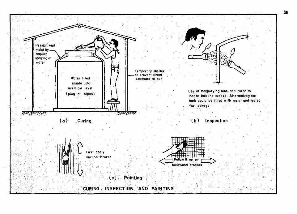
«**s^>*
Temporary shelter to prevent direct exposure to sun
( a ) Curing
Use of magnifying lens.and torch to locate hairline cracks. Alternatively the tank could be filled with water and tested for leakage
(b ) Inspection
ft 4
First apply
vertical strokes Follow It up
horizontal strokes
byrzz£>
(c ) Painting
CURING , INSPECTION AND PAINTING

Impact force
Localized area of damage. Skeletal steel and mesh have been displaced.
Mortar in the damaged area chipped off, exposing steel. Additional layers of mesh are to be provided if necessary , after steel is straightened out.
(a ) Damaged ferrocement section (c ) Chipping mortar and straightening steel
Partially replastered section prior to brushing off excessive mortar
Repaired section ready for curing
( b ) Repair partially complete ( d ) Completed section
STAGES IN REPAIRING A DAMAGED SECTION
JtC a t
A\AW ^VVW^V- ^^V^VVAV,
Wedge lift tank using, a crow-bar. Insert greased pipes beneath the tank Slide over'the greased pipes until tank is repositioned in the desired location This technique of shifting is recommended only for small shifts.
Arrangement for lifting using a mobile jib crane. Tie up hessian at places where impact damage during handling is likely
Gantry cranes on rails would prove useful for large scale plants that prefabricate tanks
MECHANISMS FOR HANDLING TANKS

About IFIC
The International Ferrocement Information Center (IFIC) was founded in October 1976 at the Asian Institute of Technology (AIT) under the joint sponsorship of the Institute's Division of Structural Engineering and Construction and the Library and Regional Documentation Center. The IFIC was established as a result of the recommendations made in 1972 by the U.S. National Academy of Sciences' Advisory Committee on Technological Innovation (ACTI). IFIC receives financial support f rom the United States Agency for International Development (USAID), the Government of New Zealand and the International Development Research Center (IDRC) of Canada.
Basically IFIC serves as a clearing house for information on ferrocement and related materials. In cooperation w i th national societies, universities, libraries, information centers, government agencies, research organizations, engineering and consulting f irms all over the wor ld , IFIC attempts to collect information on all forms of ferrocement applications either published or unpublished. This information is identified and sorted before it is repackaged and disseminated as widely as possible through IFIC's publication and on request through IFIC's reference and reprographic services.
IFIC publishes:
The quarterly Jounal of Ferrocement,
Monographs (such as Ferrocement — a comprehensive state-of-the-art review of properties and potential application of ferrocement — published in August 1978).
Simple brochures on ferrocement in various languages.
Ferrocement and its Applications—A Bibliography (Vol . 1 containing 736 items of references classified according to subject — published in November 1978).
Series of simple Do it yourself booklets on specific rural ut i l i ty structures. First booklet on Ferrocement Grain Storage Bin was published in May 1978. Two more booklets on Ferrocement Biogas Holder and Ferrocement Canoe are under draft.
IFIC also envisages to sponsor training sessions on ferrocement construction to be conducted at A I T for specialists f rom various developing countries (one such 4 month training for 9 Indonesian engineers financed by USAID was completed in October 1978). For more information on IFIC write to : The Director, International Ferrocement Information Center, Asian Institute of Technology, P.O. Box 2754, Bangkok, Thailand.
PubLLbhzd by the. lntnA.naXA.onaZ. T-QAA.oc.mznt Information ZznteA
AiAjxn Institute, ofa Technology P.O. Box 2754
Bangkok, Thailand ' Wo. 77/S0, May 1980