7SG15 – MicroTAPP -...
20
Reyrolle Protection Devices 7SG15 – MicroTAPP Automatic Voltage Control Answers for energy
Transcript of 7SG15 – MicroTAPP -...

Reyrolle
Protection
Devices
7SG15 – MicroTAPP Automatic Voltage Control
Answers for energy

Siemens Protection Devices Limited 2
7SG15 - MicroTAPP Automatic Voltage Control
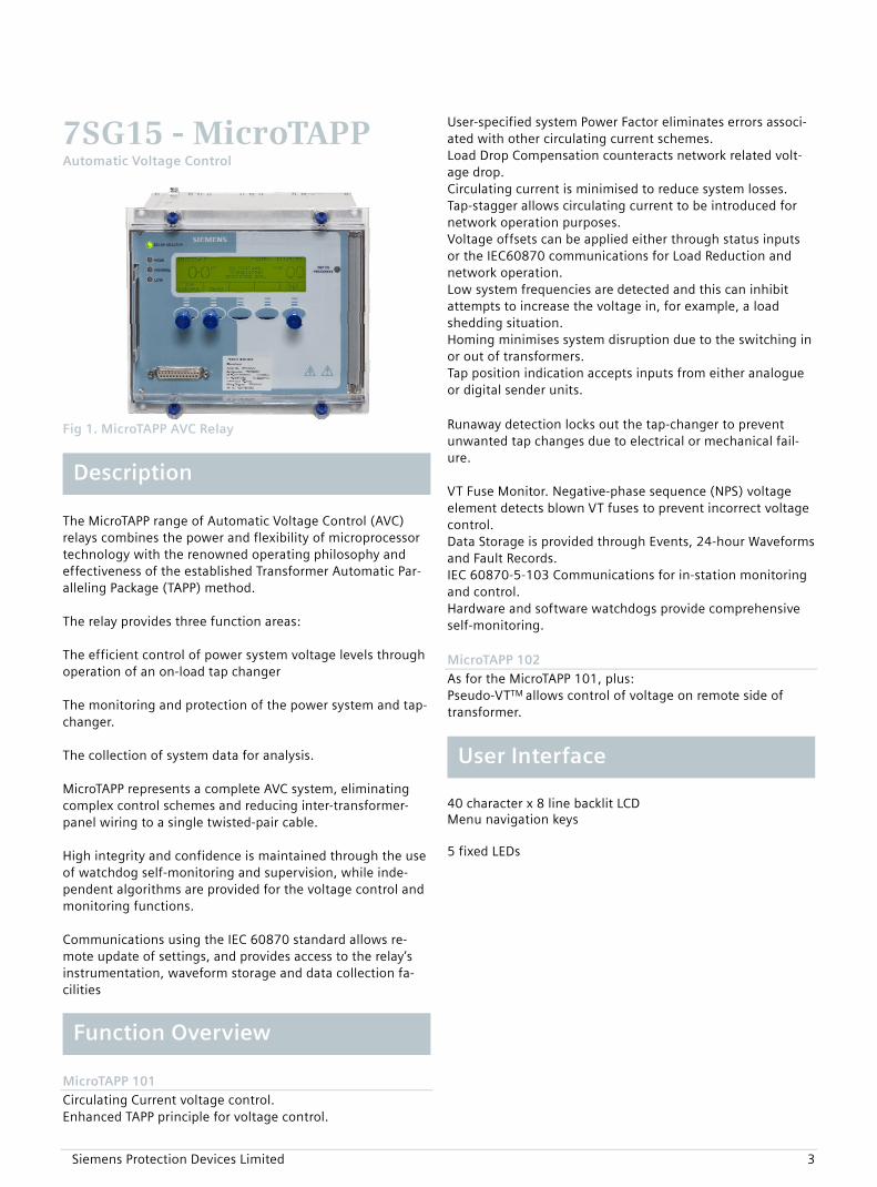
Fig 1. MicroTAPP AVC Relay
The MicroTAPP range of Automatic Voltage Control (AVC) relays combines the power and flexibility of microprocessor technology with the renowned operating philosophy and effectiveness of the established Transformer Automatic Par-alleling Package (TAPP) method. The relay provides three function areas: The efficient control of power system voltage levels through operation of an on-load tap changer The monitoring and protection of the power system and tap-changer. The collection of system data for analysis. MicroTAPP represents a complete AVC system, eliminating complex control schemes and reducing inter-transformer-panel wiring to a single twisted-pair cable. High integrity and confidence is maintained through the use of watchdog self-monitoring and supervision, while inde-pendent algorithms are provided for the voltage control and monitoring functions. Communications using the IEC 60870 standard allows re-mote update of settings, and provides access to the relay’s instrumentation, waveform storage and data collection fa-cilities
MicroTAPP 101
Circulating Current voltage control. Enhanced TAPP principle for voltage control.
User-specified system Power Factor eliminates errors associ-ated with other circulating current schemes. Load Drop Compensation counteracts network related volt-age drop. Circulating current is minimised to reduce system losses. Tap-stagger allows circulating current to be introduced for network operation purposes. Voltage offsets can be applied either through status inputs or the IEC60870 communications for Load Reduction and network operation. Low system frequencies are detected and this can inhibit attempts to increase the voltage in, for example, a load shedding situation. Homing minimises system disruption due to the switching in or out of transformers. Tap position indication accepts inputs from either analogue or digital sender units. Runaway detection locks out the tap-changer to prevent unwanted tap changes due to electrical or mechanical fail-ure.
Description VT Fuse Monitor. Negative-phase sequence (NPS) voltage element detects blown VT fuses to prevent incorrect voltage control. Data Storage is provided through Events, 24-hour Waveforms and Fault Records. IEC 60870-5-103 Communications for in-station monitoring and control. Hardware and software watchdogs provide comprehensive self-monitoring.
MicroTAPP 102 As for the MicroTAPP 101, plus: Pseudo-VTTM allows control of voltage on remote side of transformer.
User Interface
40 character x 8 line backlit LCD Menu navigation keys 5 fixed LEDs
Function Overview
Siemens Protection Devices Limited 3
Siemens Protection Devices Limited 4
Analogue values can be displayed on the LCD screen. In addition most values can be obtained via the data communications channel(s). Primary and secondary currents Primary and secondary voltages Frequency Power Factor Phase Angles Transformer & Group Load PPS and NPS voltage Tap Position Status inputs Output contacts Tap counters MPPC status
Voltage Control
The user specifies target voltage, voltage dead band, initial delay and inter-tap delay. When a voltage excursion outside the dead band occurs the MicroTAPP acts to restore correct system voltage. When de-ciding on voltage excursion the measured voltage is com-pensated for:
Load drop compensation (LDC) – compensates for voltage drop in the network. Corrective coupling voltage (CCV) – acts to eliminate current circulating between parallel transformers due to mis-matches in voltage. In service adjustments to the target voltage – ap-plied either via status inputs or IEC60870 communi-cations.
OperateTime
RelayDeadband80% Volts
InitialDelay
IDMTLInitialDelay
DTLInitialDelay
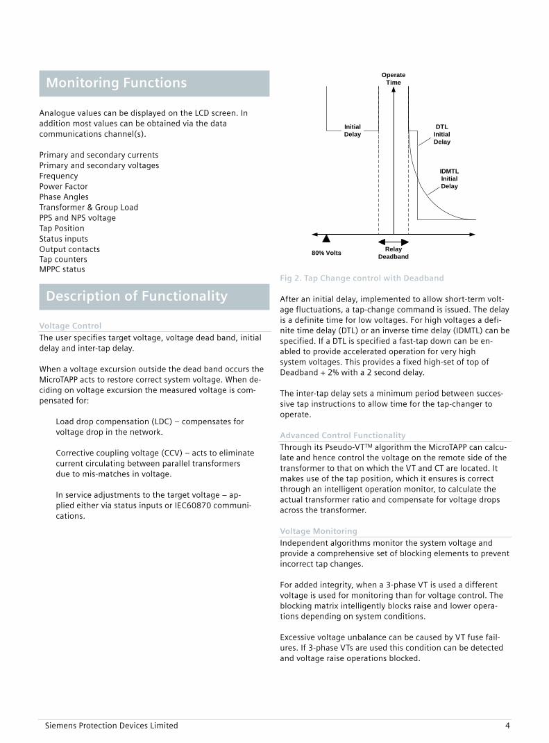
Fig 2. Tap Change control with Deadband After an initial delay, implemented to allow short-term volt-age fluctuations, a tap-change command is issued. The delay is a definite time for low voltages. For high voltages a defi-nite time delay (DTL) or an inverse time delay (IDMTL) can be specified. If a DTL is specified a fast-tap down can be en-abled to provide accelerated operation for very high system voltages. This provides a fixed high-set of top of Deadband + 2% with a 2 second delay. The inter-tap delay sets a minimum period between succes-sive tap instructions to allow time for the tap-changer to operate. Advanced Control Functionality Through its Pseudo-VTTM algorithm the MicroTAPP can calcu-late and hence control the voltage on the remote side of the transformer to that on which the VT and CT are located. It makes use of the tap position, which it ensures is correct through an intelligent operation monitor, to calculate the actual transformer ratio and compensate for voltage drops across the transformer. Voltage Monitoring Independent algorithms monitor the system voltage and provide a comprehensive set of blocking elements to prevent incorrect tap changes. For added integrity, when a 3-phase VT is used a different voltage is used for monitoring than for voltage control. The blocking matrix intelligently blocks raise and lower opera-tions depending on system conditions. Excessive voltage unbalance can be caused by VT fuse fail-ures. If 3-phase VTs are used this condition can be detected and voltage raise operations blocked.
Monitoring Functions
Description of Functionality

Siemens Protection Devices Limited 5
Voltage
TransformerLoad
Full Load(Transformer Capacity
setting)
Normal Operation
Block Raise Volts
Block Lower Volts
Total blocking
80% Volts
Lower Band
Upper BandBlock operation forexcessive LOAD
Allow operation to reduceCIRCULATING current
Block Raise Volts if VTFuse failure detected
Data Storage and Communication
Sequence of event records
Up to 200 events are stored and time tagged to 1ms resolution. These are available via the communications. Fault records
The last 10 tap-changer fault records are available from the fascia with time, date and type of failure. Graphical records Recordings of all operational data, voltage level, transformer load, summed load etc. are available for up to 24 hours. Communications
Two fibre-optic communications ports are provided on the rear of the relay. They are optimised for 62.5/125μm glass-fibre, with BFOC/2.5 (ST®) bayonet style connectors. Fig 3. Voltage monitoring blocking matrix In addition users may interrogate the relay locally with a laptop PC and the RS232 port on the front of the relay.
If an excessive current flows at normal system power factors the relay inhibits all tap-changing operations. High currents when the power factor is abnormal may be as a result of circulating currents. In this situation the relay should act to reduce them rather than applying over-current blocking.
The relay supports the IEC 60870-5-103 communications standard. Reydisp Evolution A system voltage below 80% will be due either to the Trans-
former being powered down or a system fault condition and so all tap-changing is inhibited.
Upper and Lower Alarm levels are provided to indicate ab-normal voltages. An Alarm will also be issued if the voltage remains outside the Deadband for an abnormal time. Tap-changer Monitoring An intelligent tap-position indicator and runaway prevention algorithm monitors the entire tap-change operation. A Tap-changer runaway is quickly detected and the resulting alarm can be used to lock-out the tap-changer to prevent damage to the system. Incomplete tap-changes are also detected and indicated. If the voltage requires a tap-change beyond the limits of the tap-changer this is inhibited and a target not achievable alarm is generated.
Fig 2. Typical ReyDisp Evolution screenshot This support software is common to the entire range of Reyrolle numeric products. It provides the means for the user to apply settings to the Delta as well as to retrieve settings, instruments, events, waveforms and 24 hour data.
Tap Changer Maintenance A tap-changer operations count and a “sum of I2” count is provided. Alarm levels can be set which, when reached, can be routed to a condition-based maintenance system.
For full technical data refer to the Performance Specification of the Technical Manual.
Characteristic Energising Quantity
AC Current 1, 5 A, 50/60 Hz
AC Voltage 63.5 V line-neutral, 110 V line-line, 50/60 Hz
Thermal Withstand
AC Current Inputs
continuous 3.0 xIn
10 minutes 3.5 xIn
5 minutes 4.0 xIn
2 minutes 6.0 xIn
1 second 250 A
1 cycle 625 A peak
AC Voltage Inputs
continuous 300 V
Burden
AC Current Inputs
1 A ≤ 0.1 VA
5 A ≤ 0.3 VA
AC Voltage Inputs
≤ 0.01 VA
DC Auxiliary Supply
Nominal Voltage Operating Range 30 VDC 24 to 37.5 VDC 48, 110 VDC 37.5 to 137.5 VDC 220 VDC 178 to 280 VDC 110 VAC 82.5 to 137.5 VAC RMS
Operate State Burden Quiescent (Typical) 17 W Maximum 20 W
Burdens are measured at nominal rating. Allowable superimposed ac component
≤12% of dc voltage
Allowable breaks/dips in supply (collapse to zero from nominal voltage)
≤20 ms
Status Inputs Technical Information
Nominal Voltage Operating Range 30, 34 VAC/DC 24 to 37.5 VAC/DC 48, 54 VAC/DC 37.5 to 60 VAC/DC 110, 125 VAC/DC 87.5 to 137.5 VAC/DC 220, 250 VAC/DC 175 to 280 VAC/DC Inputs and Outputs
Note that the status input voltage need not be the same as the main energising voltage. The 30V and 48V inputs meet the requirements of ESI48-4 ESI 1. However, the 110V and 220V inputs will operate with a DC current of less than 10mA. Where 110V or 220V inputs compliant with ESI48-4 ESI 1 are required, a relay with 48V binary inputs can be supplied with external series resistors as follows: Nominal Voltage Resistor Value Wattage 110V 2k7 ± 5% 2.5 W 220 V 8k2 ± 5% 6.0 W
Parameter Value Minimum DC current for operation (30 V and 48 V inputs only)
10 mA
Reset/Operate Voltage Ratio 90 % Recommended minimum pulse duration 500 ms
Output Relays
Carry continuously 5A ac or dc Make and carry (L/R ≤ 40 ms and V ≤ 300V)
20A ac or dc for 0.5s 30A ac or dc for 0.2s
Breaking Capacity ( ≤ 5 A and ≤ 300 V): AC Resistive AC Inductive DC Resistive DC Inductive
1250 VA 250 VA at p.f. ≤ 0.4 75 W 30 W at L/R ≤ 40ms 50 W at L/R ≤ 10ms
Minimum number of operations
1000 at maximum load
Minimum recommended load
0.5 W limits 10mA or 5V
Vibration(Sinusoidal)IEC 60255-21-1 Class 1
0.5 gn, Vibration response
1.0 gn, Vibration endurance
≤ 5% variation
Mechanical
Siemens Protection Devices Limited 6

Shock and Bump IEC 60255-21-2 Class 1
5 gn, Shock response, 11ms
15 gn, Shock withstand, 11ms
10 gn, Bump test, 16ms
≤ 5% variation
Seismic IEC 60255-21-3 Class 1
1 gn, Seismic Response ≤ 5% variation
Mechanical Classification
Durability In excess of 106
operations Recommended load
Minimum recommended load 0.5 W, limits 10 mA or
5 V
Insulation IEC 60255-5
RMS levels for 1 minute Between all terminals and earth 2.0 kV Between independent circuits 2.0 kV Across normally open contacts 1.0 kV
Transient Overvoltage
IEC 60255-5 Between all terminals and earth or between any two independent circuits without damage or flashover
5 kV 1.2/50 µs 0.5 J
High Frequency Disturbance
IEC 60255-22-1 Class III 2.5kV, Longitudinal mode 1.0kV, Transverse mode
≤3% variation
Electrostatic Discharge
IEC 60255-22-2 Class III 8kV, Contact discharge ≤5% variation
Fast Transient
IEC 60255-22-4 Class IV 4kV, 5/50ns, 2.5 kHz, repetitive ≤3% variation
Radio Frequency Interference
IEC 60255-22-3 10 V/m, 80 to 1000 MHz ≤5% variation
Conducted RFI
IEC 60255-22-6 10 V, 0.15 to 80 MHz ≤5% variation
Conduct limits
IEC 60255-25
Limits dB(µV) Frequency Range Quasi-peak Average
0.15 to 0.5 MHz 79 66 0.5 to 30 MHz 73 60
Radiated limits
IEC 60255-25
Electrical Tests Frequency Range Limits at 10 m Quasi-peak, dB(µV/m)
30 to 230 MHz 40 230 to 10000 MHz 47
Siemens Protection Devices Limited 7

Temperature IEC 68-2-1/2
Operating -10 °C to +55 °C
Storage -25 °C to +70 °C
Humidity IEC 68-2-3
Operational test 56 days at 40 °C and 95% RH
General Accuracy
Reference Conditions
Parameter Reference or Value
General IEC 60255-3
Current Settings 100% of In
Time Multiplier 1.0
Current input (IDMTL) 2x to 20x Is
Current input (DTL) 5x Is
Auxiliary supply Nominal
Frequency 50 Hz
Ambient temperature 20 °C
General Settings
Parameter Value
Transient Overreach of Highset/Lowset (X/R = 100)
≤ 5%
Disengaging Time (1) < 42 ms
Overshoot Time < 40 ms
Output contacts have a minimum dwell time of 100ms, after which the disengage time is as above. Indication
Relay Healthy Method Green LED Relay Failure Flashing or extinguished High, Low Voltage Method Red LEDs Voltage Alarm Flashing Normal Voltage Method Green LED Tap In Progress Method Amber LED Lockout Flashing
Settings and Instrumentation Method graphical backlit LCD Environmental
Protection Elements
Sub-station communications
Protocol IEC 60870-5-103
RS-232 interface Location Fascia Form 25-pin female D-type con-
nector Fibre interface Location Rear Quantity 2 x Rx, 2 x Tx Form BFOC/2.5 (ST®) bayonet
connector COM1 Baud rate 75-115200 baud Interface Fibre-optic port COM2 Baud rate 75-115200 baud Interface Auto-switches between
Fibre-optic and RS-232
Siemens Protection Devices Limited 8

General Accuracy
Reference conditions
Parameter Reference or Value Auxiliary Supply Nominal Frequency 50/60 Hz Ambient Temperature 20 °C
Accuracy Influencing Factors Temperature
Ambient range Variation -10 °C to +55 °C ≤ 5%
Frequency
Range Variation 47 Hz to 52 Hz Level: ≤ 5% 57 Hz to 62 Hz Operate Time: ≤ 5%
Harmonic content
Range Variation Frequencies to 550Hz Setting: ≤ 5%
Control Elements
Voltage Control Method TAPP, Circulating Current
Voltage Control Target 85 to 115% Vn Dead band ±0.1 to ±5.0% Vn Accuracy ±0.1% Vn Repeatability ±1% Initial Delay Characteristics DTL or IDMTL (voltage
high only) Setting 2 to 180 s Accuracy ±0.25 s Repeatability ±0.25 s General No of transformers 1 to 16 No of taps 1 to 39 Sender Unit Resistor chain, binary,
BCD, gray code Inter-Tap delay Setting Continuous, 1 to 120 s Accuracy 1s Repeatability 1s
Siemens Protection Devices Limited 9
Temperature IEC 68-2-1/2
Operating range -10 °C to +55 °C Storage range -25 °C to +70 °C
Humidity IEC 68-2-3
Operational test
56 days at 40 °C and 95% RH
Transient Overvoltage IEC 60255-5
Test Levels Between all terminals and earth or be-tween any two independent circuits with-out damage or flashover
5 kV 1.2/50 µs 0.5 J
Insulation IEC 60255-5
Test Level (rms for 1 min) Between all terminals and earth
2.0 kV
Between independent circuits
2.0 kV
Across normally open contacts
1.0 kV
Immunity Auxiliary DC Supply IEC 60255-11
Quantity Value Allowable superimposed ac component
≤ 12% of dc voltage
Allowable breaks/dips in supply (collapse to zero from nominal voltage)
≤ 20 ms
High Frequency Disturbance IEC 60255-22-1 Class III
Type Level Variation Common (Longitudinal) Mode 2.5 kV Series (Transverse) Mode 1.0 kV
≤ 3%
Electrostatic Discharge IEC 60255-22-2 Class III
Type Level Variation Contact discharge 8 kV ≤ 5%
Radio Frequency Interference IEC 60255-22-3
Frequency Range Level Variation 80 to 1000 MHz 10 V/m ≤ 5%
Fast Transient IEC 60255-22-4 Class IV
Type Level Variation 5/50ns, 2.5 kHz, repetitive 4kV ≤ 3%
Conducted RFI IEC 60255-22-6
Frequency Range Level Variation 0.15 to 80 MHz 10 V ≤ 5%
Emissions Conducted limits IEC 60255-25
Limits dB(ΔV) Frequency Range Quasi-peak Average
0.15 to 0.5 MHz 79 66 0.5 to 30 MHz 73 60
Radiated limits IEC 60255-25
Frequency Range Limits at 10 m Quasi-peak, dB(ΔV/m)
30 to 230 MHz 40 230 to 10000 MHz 47
Mechanical
Environmental
Vibration Sinusoidal IEC 60255-21-1 Class 1
Type Level Variation Vibration response 0.5 gn Vibration endurance 1.0 gn
≤ 5%
Shock and Bump IEC 60255-21-2 Class 1
Type Level Variation Shock response, 11ms 5gn Shock withstand, 11ms 15gn Bump test, 16ms 10gn
≤ 5%
Seismic IEC 60255-21-3 Class 1
Type Level Variation Seismic Response 1 gn ≤ 5%
Mechanical Classification
Durability In excess of 106 operations
Siemens Protection Devices Limited 10

Siemens Protection Devices Limited 11
Voltage Control The following standard system conditions should be ca-tered for with minimal or no adjustment to the Automatic Voltage Control System (AVC): Where a transformer operates in parallel with other trans-formers, either within a site or across a network, the AVC should operate in order to (a) maintain the system volt-age at the correct level and (b) operate at a tap position where minimal reactive circulating current flows from or into any system transformer which is a part of the net-work. In the event of a failure of communications either be-tween grouped transformers or from a remote control centre, the AVC should be able to operate in a stand-alone mode and achieve a satisfactory overall system voltage. If a transformer in a group is switched IN, no significant change in voltage will occur. If a transformer in a group is switched OUT, no significant change in voltage will occur. The Load Drop Compensation (LDC) method, if used, must remain at the correct level regardless of the number of transformers connected to a common busbar. Settings applicable to different network running arrangements should be applied to the AVC and be capa-ble of implementation by a single instruction (either from a remote source or locally) or plant status change. The AVC must be provided with the capability of inde-pendently protecting against incorrect operation which would allow abnormal voltages to be applied to the net-work. The AVC shall be capable of controlling at least 16 trans-formers operating in parallel as a group. The operating characteristics of the voltage regulating relay is to be such that a raise or lower command will only be issued after an initial time delay as set on the voltage regulating relay. A definite time characteristic and an inversely related initial time characteristic shall be select-able. When a definite time delay is selected a fast tapping feature which bypasses the initial time delay in the event of substantial voltage excursions above the set band is preferred. Any subsequent corrective signals for the same voltage deviation will be delayed by a separate inter-tap time delay. The voltage regulating relay shall include a ‘Load Drop Compensation’ facility. LDC shall be used where the bus-bar voltage is increased in proportion to the total substa-tion load current. The LDC effect shall be proportional to
the total connected busbar load. This method will provide the correct voltage boost given by the chosen LDC set-ting, irrespective of the number of transformers in ser-vice. Full LDC functionality shall be retained when parallel control based on the minimum circulating current method is used. Voltage Monitoring Monitoring of the voltage level shall be via separate con-nections to those used for voltage control. If the measured system voltage is less than a pre-set un-der-voltage limit or greater than a pre-set over-voltage limit, the system shall inhibit the appropriate tap control outputs to the relevant transformer but allow tap change operations that will correct the abnormal voltage. An alarm will be generated if the abnormal voltage persists. Where a 3 phase VT is used the system shall monitor all voltages in order to ensure the integrity of the VT secon-dary output. Any abnormalities detected will inhibit the voltage raise outputs from the system and initiate an alarm. If the load current is greater than a pre-set limit, the sys-tem shall inhibit all tap control outputs to the relevant transformer(s) and generate an alarm, unless the situa-tion is caused by circulating current flowing between transformers. In this case tap changing will be allowed to reduce the circulating current. Tap-changer Monitoring The tap changer operation monitor circuits shall be pro-vided for tap changer runaway protection in the event of a mechanism, wiring or relay fault. The following shall be considered minimum requirements for such protection: Protection is required that will detect incorrect tap change operation at the earliest opportunity. An incorrect tap change operation is defined as “a tap change opera-tion that is not initiated by a ‘true’ control signal”. As an example, a slow to clear ‘raise’ contactor may allow a motor drive to continue driving the mechanism at the end of a tap change cycle such that the tap change maintain-ing switch recloses and thus allows the tap change to ‘run away’. The preferred scheme should not rely on timing systems for determination of this situation, but intelli-gently monitor the relationship between the control sig-nals, the tap change in progress inputs and the tap posi-tion.
If a lockout is required the AVC will initiate contacts both for lockout and alarms. The lockout contacts shall provide for the tripping of a mechanically latched contac-tor or the permissive operation normally open contactor to remove the tap change motor power supply. Inputs from plant
Sample Specification

Siemens Protection Devices Limited 12
To avoid drain on substation batteries, the tap changer control supply will provide the supply for all AVC equip-ment and have a nominal AC voltage of 110V (+10% to –25%). Measuring voltage inputs shall be provided which are capable of operating with VTs with secondary rating be-tween 63.5 and 250V. Adjustment shall be provided to eliminate any VT ratio errors. A measuring current input shall be provided capable of operating with CTs of 1 or 5A secondary rating. The relay shall be configurable to allow non-standard CT ratios to be used. The relay shall be capable of using the CT re-gardless of the phase to which it may be connected. The relay shall be capable of measuring up to 39 tap positions, including special tap positions (e.g. 8A, 8B, 8C) from resistor chain, BCD, binary and gray code sender units. A tap-change in progress (TCIP) signal shall be detected by the relay from a contact provided in the tap changer. The TCIP contact will close as the tap change starts and open at the end of the tap change sequence. Outputs to plant The tap raise/lower outputs shall be via normally open clean contacts with a minimum pulse time of 1.5s rated for 5A AC. The AVC system will be required to prevent operation of the tap changer motor drive in the event of unwanted operations. Two methods may be used: Tripping of a mechanically latched contactor connected into the supply for the motor Permissive operation of a normally de-energised contac-tor connected into the motor supply during the tap changing sequence To enable either option, change-over clean output con-tacts rated for at least 5A AC shall be provided. Operator Controls The AVC system shall provide the means to: Switch control points between local (at the AVC) and remote (network control centre). Switch between local and automatic control. Raise and lower the tap-changer manually. When set to local it shall not be possible for a remote point to operate the tap-changer or switch the AVC be-tween manual and automatic modes. If a Master/Follower tap change control scheme is pro-posed, additional control switches will be required. A
Master/Follower design is NOT the preferred scheme for submission as a solution. Indication and instrumentation The following indications shall be provided: Circuit identifier AVC healthy LED Voltage normal/high/low LEDs Tap in progress LED Voltmeter showing system voltage Tap position indication, allowing for unusual tap ar-rangements (e.g. 8A, 8B, 8C) Indication of transformer load, transformer load power factor and total load of all paralleled transformers Remote Access Remote access shall be provided through both hard-wired inputs and outputs, and using a non-proprietary commu-nications protocol, e.g. IEC 60870-5-103. The following features shall be available using both access methods: When the AVC system is set to remote, it will be possible to switch the AVC between automatic and manual. When in manual, it will be possible to operate the tap-changer from a remote point. It will be possible to select between a minimum of 3 pre-set voltage targets. Alarms will be provided for AVC failure, VT fuse failure, voltage out of limits, tap-changer runaway, tap-change incomplete, target not achievable. The following data shall be made available using the communications protocol: Metering values of voltage, load, power factor and tap position. Traces of voltage, current, tap position, frequency and a measure of power quality for a minimum period of 24 hours.
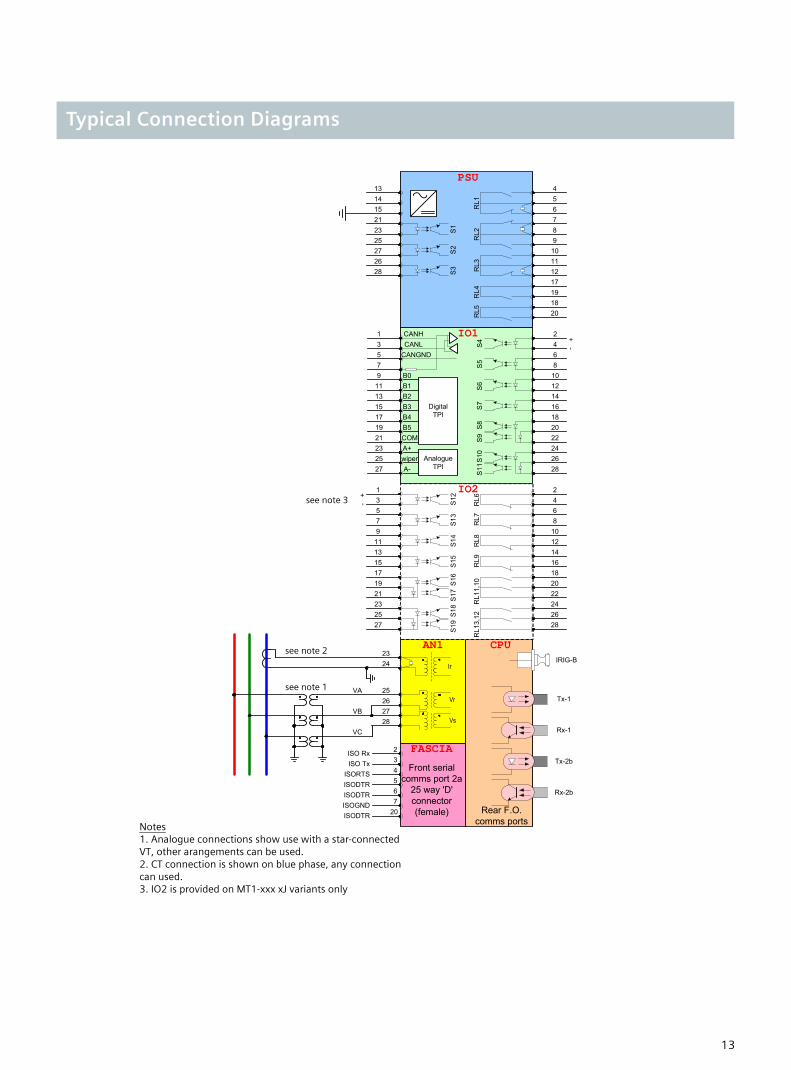
Typical Connection Diagrams
S1
S3
S2
13
2826272523211514
7531
1513119
171921
+-
8642
16141210
182022242628
654
10987
111217191820
S16
S17
S14
S15
S13
S12
232527
S18
S19
RL1
3,12
RL1
1,10
RL9
RL8
RL7
RL6
PSU
IO1
IO2
AN1 CPU
FASCIA
RL1
RL2
RL3
RL4
RL5
Front serialcomms port 2a
25 way 'D' connector(female)
IRIG-B
Rx-2b
Tx-2b
Rx-1
Tx-1
2423
25
282726
VA
VC
VB
Rear F.O.comms ports
Notes
1. Analogue connections show use with a star-connected VT, other arangements can be used.2. CT connection is shown on blue phase, any connection can used.3. IO2 is provided on MT1-xxx xJ variants only
Ir
Vr
Vs
ISO Rx
207
23456
ISODTR
ISO TxISORTSISODTRISODTRISOGND
S5
S4
8642
16141210
182022242628
+-
S7
S6
S9
S8
S10
S11
7531
1513119
171921232527
B0B1B2B3B4B5COM
CANGNDNLNH
CACA IO1
Analogue TPI
Digital TPI
A+wiperA-
see note 1
see note 2
see note 3
13
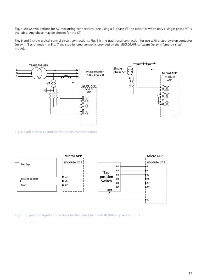
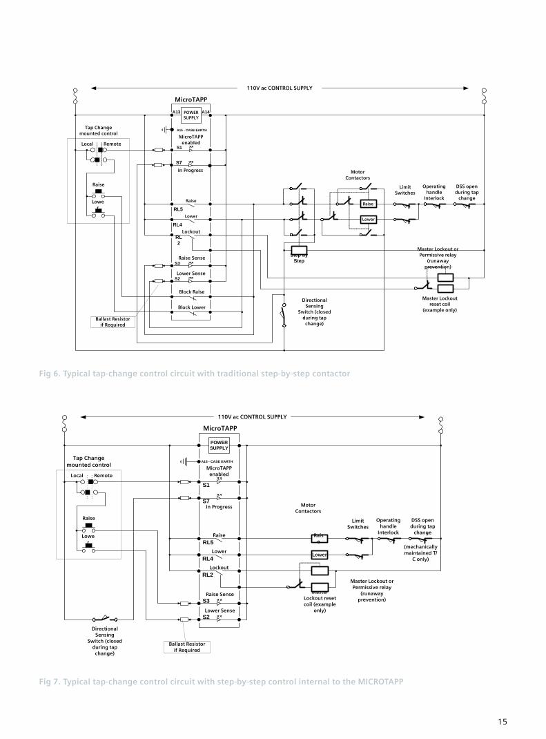
Fig. 4 shows two options for AC measuring connections, one using a 3-phase VT the other for when only a single-phase VT is available. Any phase may be chosen for the CT. Fig. 6 and 7 show typical control circuit connections. Fig. 6 is the traditional connection for use with a step-by-step contactor (relay in ‘Basic’ mode). In Fig. 7 the step-by-step control is provided by the MICROTAPP software (relay in ‘step-by-step’ mode).
VT
TRANSFORMER
Phase rotationA-B-C or A-C-B
ABC c
ba
MicroTAPP
25
26
2728
23
24
module AN1
Single phase VT MicroTAPP
25
26
27
28
23
24
module AN1
Fig 4. Typical voltage and current measurement inputs
Tap 1
Top Tap
Moving contact23
25
27
MicroTAPP
21
9
11
13
15
17
19
B0
B1
B2
B3
B4
B5COM
Tap position Switch
module IO1 module IO1
MicroTAPP
Fig5. Tap position input connections for Resistor Chain and BCD/Binary sender units
14
Motor Contactors
Step by Step
Directional Sensing
Switch (closed during tap
change)
DSS open during tap
change
Operating handle
Interlock
Limit Switches
Lower
Raise
Master Lockoutreset coil
(example only)
110V ac CONTROL SUPPLY
Raise
Local Remote
Lower
Tap Change mounted control
S2
RL5
RL4
RL2
POWER SUPPLY
A13 A14
S3
MicroTAPP
Raise
Lower
Lockout
A15 - CASE EARTH
Master Lockout orPermissive relay
(runaway prevention)
Raise Sense
Lower Sense
Block Raise
Block Lower
Ballast Resistorif Required
MicroTAPPenabled
S1
S7In Progress
Fig 6. Typical tap-change control circuit with traditional step-by-step contactor
Motor Contactors
DSS open during tap
change
Operating handle
Interlock
Limit Switches
Lower
Raise
110V ac CONTROL SUPPLY
Raise
Local Remote
Lower
Tap Change mounted control
(mechanically maintained T/
C only)
Directional Sensing
Switch (closed during tap
change)
POWER SUPPLY
MicroTAPPenabled
Raise
Lower
Lockout
RL4
RL5
S1
S2
S3
S7
RL2
A15 - CASE EARTH
Raise Sense
Lower Sense
In Progress
Master Lockout reset coil (example
only)
Master Lockout or Permissive relay
(runaway prevention)
Ballast Resistorif Required
MicroTAPP Fig 7. Typical tap-change control circuit with step-by-step control internal to the MICROTAPP
15

MPPC Screend twisted pair cable
MPPC line terminator link
MPPC line terminator link
MPPC screen earthing at a single point
MicroTAPP 1
13 5
7
Intermediate MicroTAPP
13 5
7
MicroTAPP N
1 35
7
module IO1 module IO1 module IO1
Fig 8. Connections for MicroTAPP peer-peer communications (MPPC)
Operating handle
InterlockLimit Switches
Master Lockout Relay trip or
Permissive close(runaway
prevention)
RaiseContactor
LowerContactorIsolator
Overload
Motor3 phase power supply
Maintaining switch driven by
mechanismRaise
Lower
Fig 9. Typical tap-change motor circuit
16

The MicroTAPP is supplied in either a size 8 or size 12 case, depending on the status input and output relay requirement, see the table below.
Fig 10. Overall Dimensions and panel drilling for Epsilon E8 case
Case Drawing
Fig 11. Overall Dimensions and panel drilling for Epsilon E12 case
17

Ordering Information - MICROTAPP 7SG151
Product description Variants Order No.
MICROTAPP 7 S G 1 5 □ 0 - □ □ □ □ □ - 0 □ □ 0 ▲ ▲ ▲ ▲ ▲ ▲ ▲ ▲
Transformer tap change control and monitoring. | | | | | | | | | | | | | | | | Relay type | | | | | | | | Automatic voltage control (AVC) 1 | | | | | | | | | | | | | | Protection options | | | | | | | Basic - Microprocessor based automatic voltage control (AVC)
system operating on the well proven TAPP philosophy
1 | |
| | |
| | |
| | |
| | |
| | |
| | |
Advanced - As basic model only particularly suitable for em-bedded generation and traction system applications as this model is capable of controlling the HV or LV voltage
2 | | |
| | |
| | |
| | |
G | |
| | |
| | | | | | Auxiliary supply /binary input voltage | | | | | | 30 V DC auxiliary, 30 V DC/AC binary input A | | | | | 30 V DC auxiliary, 48 V DC/AC binary input B | | | | | 48/110 V DC auxiliary, 30 V DC/AC binary input C | | | | | 48/110 V DC auxiliary, 48 V DC/AC binary input 1) D | | | | | 48/110 V DC auxiliary, 110 V DC/AC low burden binary input E | | | | | 220 V DC auxiliary, 110 V DC/AC low burden binary input F | | | | | 220 V DC auxiliary, 220 V DC/AC low burden binary input G | | | | | 110 V AC auxiliary, 110 V DC/AC binary input H | | | | | 110 V AC auxiliary, 48 V DC/AC binary input X | | | | | 110 V AC auxiliary, 220 V DC/AC binary input J | | | | | 110 V AC auxiliary, 30 V DC/AC binary input K | | | | | | | | | | I/O range | | | | | 11 Binary Inputs / 5 Binary Outputs (incl. 3 changeover) E | | E | 19 Binary Inputs / 13 Binary Outputs (incl. 3 changeover and
4 normally closed contacts) J
| | |
| |
G |
| |
19 Binary Inputs / 13 Binary Outputs (incl. 3 changeover) K | | G | | | | | Frequency | | | | 50/60Hz 3 | | | | | | Nominal current | | | 1/ 5 A 0 | | | | Housing size | | Case size E8 (4U high) E | Case size E12 (4U high) G | | Communication interface | Fibre optic (ST-connector) / IEC 60870-5-103 A
1) High burden 110/125V & 220/250V binary inputs compliant with ESI48-4 ESI 1 available via external dropper resistors with 48V binary input version 110/125 V application, order combination of the following resistor boxes to suit number of binary inputs VCE: 2512H10064 (9 inputs, 110V) VCE:2512H10065 (5 inputs, 110V) VCE:2512H10066 (1 inputs, 110V) 220/250 V application, order resistor box 2512H10066 in addition VCE:2512H10067 (5 inputs, 220V) VCE:2512H10068 (1 inputs, 220V) Refer to website for application note about ESI48-4 compliance 2) For use with resistor sender units, order mounting bracket assembly with 19 off 220ohm resistors – VCE:2512H10072 3) Milliamp transducer FTPT, order 7XG2300-1AA00-0AA0 Averaging VT FAVT, order 7XG2300-2AA00-0AA0 Tap position indication module FTIM, order 7XG2300-3AA00-0AA0
18

19
20
www. siemens.com/energy
Published by and copyright © 2010:
NE31 1TZ
United Kingdom
Phone: +44 (0)191 401 7901
Fax: +44 (0)191 401 5575
www.siemens.com/energy
For more information, please contact our
Customer Support Center.
Phone: +49 180/524 70 00
Fax: +49 180/524 24 71(Charges depending on provider)
E-mail: [email protected]
Power Distribution Division Order No. E53000-K7076-C23-1
Printed in Fürth
Printed on elementary chlorine-free bleached paper.
All rights reserved.
Trademarks mentioned in this document are the property of Siemens AG, its affili-
ates, or their respective owners.
Subject to change without prior notice.
The information in this document contains general
descriptions of the technical options available, which
may not apply in all cases. The required technical
options should therefore be specified in the contract.
Hebburn
Tyne & Wear
North Farm Road
P.O. Box 8
Siemens Protection Devices Limited
Freyeslebenstrasse 1
91058 Erlangen, Germany
Siemens AG
Energy Sector