034 402 24 94 Energieberatungsstelle Region Emmental 034 402 24 94.
8/6/2019 7.IJAEST Vol No 6 Issue No 1 a Design Approach for Vehicle Black Box System Using FPGA Basd LIN Controller 031 034
http://slidepdf.com/reader/full/7ijaest-vol-no-6-issue-no-1-a-design-approach-for-vehicle-black-box-system 1/4
A Design Approach for Vehicle Black Box System Using FPGA Based LINController
1 Nikhil Wyawahare 2 Milind khanapurkar 1 Research student, ECE Department 2 Professor, Head of Department , ECE Department G.H. Raisoni college of Engineering G.H.Raisoni College of Engineering
Nagpur, India Nagpur, India [email protected] [email protected]
Abstract — a design approach for vehicle Black Box system usingFPGA Based LIN Controller. It is proposed that the system willconsists of monitor as LIN Controller. Which on activation test itsrun application after authentication it will form packets of emergency data depending upon spontaneous situation & risk;Packets which are generated through LIN Controller namely flowsin all network buses which are connected to LIN master andSlaves. As on the same time packets are store into the memorywhich is present in FPGA as a Black Box for vehicle. Stored datawe can retrieve for analysis to see accident cause or anyemergency situation occurs. Analog to digital conversion isrequired for digital data in along with controller for Black Box.Fully hardware is responsible for sensed data in to memory part of Black Box and VHDL language is used for coding
Index Term- LIN – Local Interconnect network, ADC-Analog to digital convertor, FPGA- Field programmable gatearray, DIP – Dual In Line package.
I. INTRODUCTION
new technology tell for future to do fully automatedsystem may call as good driving experience with driver comforts and safety. But it is also look after for
economical standard in today’s world. As expectation fromvehicular manufacture, researchers led to design easilyinterlinking with ECU part now are very common. ECU partrequired the communication media with intelligent system mayknown as controller mostly the controller having its internal busmechanism that will help to communicate with each other. HereLIN act as Controller which having one master and we candesign system up to 16 salves which are connected to its master with link called as bus. LIN is used for controlling betweencontroller and device. The LIN is a serial communication
protocol which efficiently supports the control of mechatronicnodes in distributed automotive applications. Lin bus has Singlemaster / multiple slaves (maximum 16) configuration with self synchronized low cost silicon single wire implementation witharound 20 k bits/ s data transfer rate. Master task is allowed totransmit the message header and slave task responds to theheader. Because there is no arbitration, to avoid error multipleslave reception, the slave is specified with application. Themaster checks the Consistency of message and can changemessage schedule. To reduce the power consumption of thesystem, a LIN node may be sent to sleep node which has nointernal activity & passive bus driver. A new methodology is
now demanded more where vehicle communicate with theworld, devices with them this will create more opportunity todevelop advanced communication devices which are isn’t smartto tell its status and its internal working pro forma at same timeof activation or in the middle of journey. A smart vehicle isalways look after on its all devices which is sensed every sometime instances decided by the programmer.
Paper is divided into sixth sections; Section 2 narratesreview and discussion related to LIN protocol and design for hardware structure. Electronic Control units (ECUs), hardwareused components
II. REVIEW & DESIGN
By the use of LIN protocol a design approach is made of,like to stored Speed, temperature, and sound etc. sensor whichis used to detect the physical change in environmentsurrounding to vehicle which is under test. A sensed data isnever to be look directly as digital stage. Then there is moralresponsibility to convert it first into digital one. Then and thensome action which is assumed to be consider for controlledsensed data in. for digital conversion ADC0809CCN is used assuccessive approximation style of conversion. ICADC0809CCN is in DIP package 28 pin. Here pin no 26and 27are used for input data. When logic 1 to the soc pin; conversion
process started as action is taken on to the analog sensed data;rate of conversion is fully depend on the pin no 11, 12, 9 these
pins are used for threshold value comparison here we kept all of these on + 5v (logic 1). And pin no 23, 24, 25 are used for channel selection.
As one more important thing is consider when we areworking with FPGA kit it required + 3.3v supply input dataonly. For that we are familiar to use a 3.3v zener diode after data out from ADC controller same for all D0-D7 bit. Digitizeddata is stored according to the controller action.
A three channel ADC controller is used to select proper input that is sensor part for vehicle. For our data input we areconsidering three different types of sensor. A first sensor isused for audio, second for temperature and third last but notleast speeds. For audio recording a condenser mic is used tosense driver conversation, mic gives analog voltage equivalentto audio after amplifying these voltages by using IC 741 it isgiven to pin no 26 of ADC0809CCN.
A
Nikhil Wyawahare et al. / (IJAEST) INTERNATIONAL JOURNAL OF ADVANCED ENGINEERING SCIENCES AND TECHNOLOGIESVol No. 6, Issue No. 1, 031 - 034
ISSN: 2230-7818 @ 2011 http://www.ijaest.iserp.org. All rights Reserved. Page 31
8/6/2019 7.IJAEST Vol No 6 Issue No 1 a Design Approach for Vehicle Black Box System Using FPGA Basd LIN Controller 031 034
http://slidepdf.com/reader/full/7ijaest-vol-no-6-issue-no-1-a-design-approach-for-vehicle-black-box-system 2/4
For temperature measure we used LM 35 which is small insize and give 10mv/°c value output for every sensation. Itsvalue is always in analog is required to be convert in to digitalso after digital conversion its input is given to the pin no 27 of IC0809CCN.
Finally for Speed is directly measure from such sensor which gives digital pulses for any motion; here motion is takenfrom vehicle wheel rotation. For demo purpose we consider asopto-coupler. Here selection of which channel is now to beused is totally depend on the controller code program. As wecan manually also check for each sensor for that just we have todo a contact of input to pin no 26 and 27 respectively to IC0809CCN manually at one time one in put only.
Complete hardware is going to be run on the power supplyof +9v battery. A most of IC are run on the + 5v supply. Then L7805 IC is used to convert as desired value for operation. Againwe are coming for FPGA section as digital input is givenseparately to FPGA input configured port. So we used single
bug connector. Before every bug point zener diode is active to3.3 values.
III. LIN INTERFACE MODULE
Clk Rd_n
Cs_nWe_n
AdDiD0
Int
Figure: 1 . LIN moduleFigure: 1 shows block schematic of typical LIN module.
Figure: 2 Block diagram of vehicular black box system
Figure: 2 shows that the data packet thus formed will betransmitted to all the Subsystems via networks in the vehicle.The subsystem depending upon the data will operate and willtake action. Main action of black box is to store every inputwhich is sensed from device. Here code for memory is totallydepend on the memory size for testing purpose we keep as 64
bytes of value which led to 0 to 15 address line. As we canincrease the memory size by increasing only address line no.
thus we are mention that FPGA kit is Xilinx Spartan-3XC3S200, FT256AF, D1345180A, 4C use by us that havingstandard memory size 256 kb. So we are working on thatsupport only.
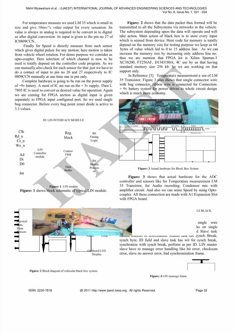
In Reference [5] Temperature measurement a use of LM35 Transistor. Figure 3 also shows that single connector wirewith bug connector, ribbon wire is connected for Connection.+ 9v battery system for power driven to whole circuit designwhich is much more economy.
Figure: 3 Actual hardware for Block Box System
Figure: 3 shows that actual hardware for the ADCcontroller and sensors like for Temperature measurement LM35 Transistor, for Audio recording; Condenser mic withamplifier circuit. And also we can sense Speed by using Opto-coupler. All these connection are made with A1 Expansion Slotwith FPGA board.
IV. A DESIGN APPROACH TO INTELLIGENT VEHICLE BLACK BOX SYSTEM
In Reference [1] LIN is low cost single wireimplementation with speed of 20kbit/s It works on singlemaster multiple slave concept. Master task and Slave task handle transfer of information. Master task has Synch. Break,synch byte, ID field and slave task has wit for synch break,synchronize with synch break, perform as per ID. LIN master slave have to manage error handling like bit error, checksumerror, slave no answer error, bad synchronization frame.
Figure: 4 LIN massage frame
FPGALIN
Controller Black Box
System
On ChipMemory
RecordedAudio Temp
PhysicalDataFrom
Sensors
Audio
Temp.
ADC0809
On Board LEDDisplay
LINController
module
Reg. block
ControlFSM
DataBuffer
BitStreamProcess
or
BitTimingLogic
Nikhil Wyawahare et al. / (IJAEST) INTERNATIONAL JOURNAL OF ADVANCED ENGINEERING SCIENCES AND TECHNOLOGIESVol No. 6, Issue No. 1, 031 - 034
ISSN: 2230-7818 @ 2011 http://www.ijaest.iserp.org. All rights Reserved. Page 32
8/6/2019 7.IJAEST Vol No 6 Issue No 1 a Design Approach for Vehicle Black Box System Using FPGA Basd LIN Controller 031 034
http://slidepdf.com/reader/full/7ijaest-vol-no-6-issue-no-1-a-design-approach-for-vehicle-black-box-system 3/4
Message Frame:
All LIN uses a single message frame format tosynchronize and address the nodes and exchange the data
between them. The master defines the transmission speed andsends the header of the message frame see figure 4.This header starts with a sync brake followed by a synch field tosynchronize the LIN slaves to the master’s bit rate. The ID is
the last header block; it holds information about the sender,receiver and data field length.
In Reference [2] states that proposed a design approachesfor intelligent vehicle safety system. A proposed safety systemwill look after the emergency data handling for in-vehiclenetworking Thus in emergency Situations, the system will
provide or pass on the data to all the sub systems/ buses, whichare operating in the vehicle. The Data will be passed on tosubsystems through LIN bus. The nodes (subsystems)connected in the network on emergency situation data receptioncan take the appropriate action. The data will also get registeredor stored in the Black Box within the system for making thefurther analysis of emergency situations.
V. SIMULATION RESULTS
Figure: 5 Code Compilation Windows
Figure: 5 show that VHDL code compilation window for the ADC Controller, Black box (LIN Controller), with memorycode.
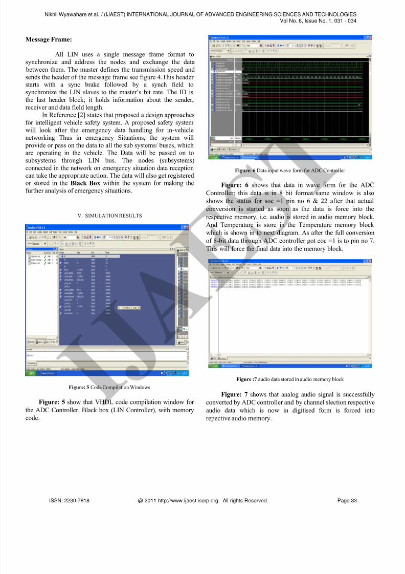
Figure: 6 Data input wave form for ADC Controller
Figure: 6 shows that data in wave form for the ADCController; this data is in 8 bit format same window is also
shows the status for soc =1 pin no 6 & 22 after that actualconversion is started as soon as the data is force into therespective memory, i.e. audio is stored in audio memory block.And Temperature is store in the Temperature memory block which is shown in to next diagram. As after the full conversionof 8-bit data through ADC controller got eoc =1 is to pin no 7.This will force the final data into the memory block.
Figure :7 audio data stored in audio memory block
Figure: 7 shows that analog audio signal is successfully
converted by ADC controller and by channel slection respectiveaudio data which is now in digitised form is forced intorepective audio memory.
Nikhil Wyawahare et al. / (IJAEST) INTERNATIONAL JOURNAL OF ADVANCED ENGINEERING SCIENCES AND TECHNOLOGIESVol No. 6, Issue No. 1, 031 - 034
ISSN: 2230-7818 @ 2011 http://www.ijaest.iserp.org. All rights Reserved. Page 33
8/6/2019 7.IJAEST Vol No 6 Issue No 1 a Design Approach for Vehicle Black Box System Using FPGA Basd LIN Controller 031 034
http://slidepdf.com/reader/full/7ijaest-vol-no-6-issue-no-1-a-design-approach-for-vehicle-black-box-system 4/4
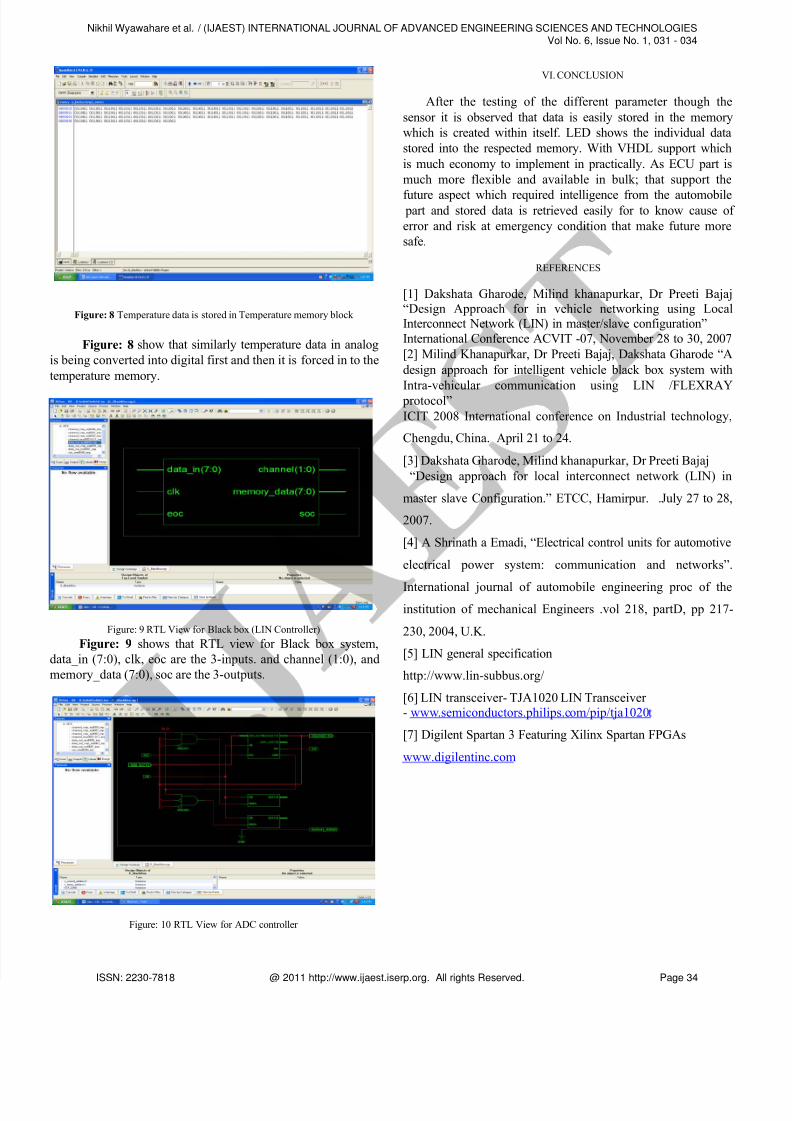
Figure: 8 Temperature data is stored in Temperature memory block
Figure: 8 show that similarly temperature data in analogis being converted into digital first and then it is forced in to thetemperature memory.
Figure: 9 RTL View for Black box (LIN Controller)
Figure: 9 shows that RTL view for Black box system,data_in (7:0), clk, eoc are the 3-inputs. and channel (1:0), andmemory_data (7:0), soc are the 3-outputs.
Figure: 10 RTL View for ADC controller
VI. CONCLUSION
After the testing of the different parameter though thesensor it is observed that data is easily stored in the memorywhich is created within itself. LED shows the individual datastored into the respected memory. With VHDL support whichis much economy to implement in practically. As ECU part ismuch more flexible and available in bulk; that support the
future aspect which required intelligence from the automobile part and stored data is retrieved easily for to know cause of error and risk at emergency condition that make future moresafe.
REFERENCES
[1] Dakshata Gharode, Milind khanapurkar, Dr Preeti Bajaj“Design Approach for in vehicle networking using LocalInterconnect Network (LIN) in master/slave configuration”International Conference ACVIT -07, November 28 to 30, 2007 [2] Milind Khanapurkar, Dr Preeti Bajaj, Dakshata Gharode “Adesign approach for intelligent vehicle black box system withIntra-vehicular communication using LIN /FLEXRAY
protocol”ICIT 2008 International conference on Industrial technology,
Chengdu, China. April 21 to 24.
[3] Dakshata Gharode, Milind khanapurkar, Dr Preeti Bajaj“Design approach for local interconnect network (LIN) in
master slave Configuration.” ETCC, Hamirpur. .July 27 to 28,
2007.
[4] A Shrinath a Emadi, “Electrical control units for automotive
electrical power system: communication and networks”.
International journal of automobile engineering proc of theinstitution of mechanical Engineers .vol 218, partD, pp 217-
230, 2004, U.K.
[5] LIN general specification
http://www.lin-subbus.org/
[6] LIN transceiver- TJA1020 LIN Transceiver - www.semiconductors.philips.com/pip/tja1020t
[7] Digilent Spartan 3 Featuring Xilinx Spartan FPGAs
www.digilentinc.com
Nikhil Wyawahare et al. / (IJAEST) INTERNATIONAL JOURNAL OF ADVANCED ENGINEERING SCIENCES AND TECHNOLOGIESVol No. 6, Issue No. 1, 031 - 034
ISSN: 2230-7818 @ 2011 http://www.ijaest.iserp.org. All rights Reserved. Page 34