787 Airplane Characteristics for Airport PlanningREVISION DATE: D6-58333 REV L December 2015 ....
171
CAGE Code 81205 787 Airplane Characteristics for Airport Planning DOCUMENT NUMBER: REVISION: REVISION DATE: D6-58333 REV L December 2015 CONTENT OWNER: Boeing Commercial Airplanes All revisions to this document must be approved by the content owner before release.
Transcript of 787 Airplane Characteristics for Airport PlanningREVISION DATE: D6-58333 REV L December 2015 ....
CAGE Code 81205
787 Airplane Characteristics for Airport Planning
DOCUMENT NUMBER: REVISION: REVISION DATE:
D6-58333 REV L December 2015
CONTENT OWNER:
Boeing Commercial Airplanes
All revisions to this document must be approved by the content owner before release.
787-10 INFORMATION IS PRELIMINARY
D6-58333
REV L December 2015 ii
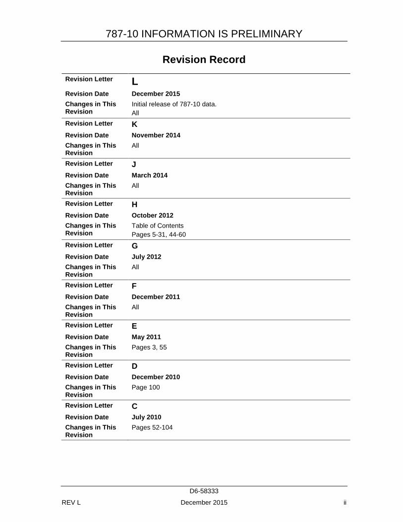
Revision Record Revision Letter L Revision Date December 2015 Changes in This Revision
Initial release of 787-10 data. All
Revision Letter K Revision Date November 2014 Changes in This Revision
All
Revision Letter J Revision Date March 2014 Changes in This Revision
All
Revision Letter H Revision Date October 2012 Changes in This Revision
Table of Contents Pages 5-31, 44-60
Revision Letter G Revision Date July 2012 Changes in This Revision
All
Revision Letter F Revision Date December 2011 Changes in This Revision
All
Revision Letter E Revision Date May 2011 Changes in This Revision
Pages 3, 55
Revision Letter D Revision Date December 2010 Changes in This Revision
Page 100
Revision Letter C Revision Date July 2010 Changes in This Revision
Pages 52-104
787-10 INFORMATION IS PRELIMINARY
D6-58333
REV L December 2015 iii
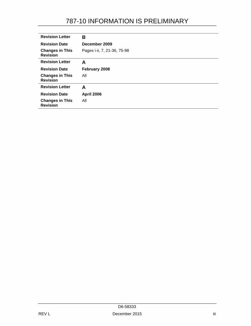
Revision Letter B Revision Date December 2009 Changes in This Revision
Pages i-ii, 7, 21-36, 75-98
Revision Letter A Revision Date February 2008 Changes in This Revision
All
Revision Letter A Revision Date April 2006 Changes in This Revision
All
787-10 INFORMATION IS PRELIMINARY
D6-58333
REV L December 2015 iv
Table of Contents 1.0 SCOPE AND INTRODUCTION ........................................................................... 1-1
1.1 SCOPE .............................................................................................................. 1-1 1.2 INTRODUCTION ............................................................................................ 1-2 1.3 A BRIEF DESCRIPTION OF THE 787 FAMILY OF AIRPLANES ............. 1-3
2.0 AIRPLANE DESCRIPTION.................................................................................. 2-1 2.1 GENERAL CHARACTERISTICS .................................................................. 2-1
2.1.1 General Characteristics: Model 787-8 ................................................... 2-2 2.1.2 General Characteristics: Model 787-9 ................................................... 2-3 2.1.3 General Characteristics: Model 787-10 ................................................. 2-4
2.2 GENERAL DIMENSIONS .............................................................................. 2-5 2.2.1 General Dimensions: Model 787-8 ........................................................ 2-5 2.2.2 General Dimensions: Model 787-9 ........................................................ 2-6 2.2.3 General Dimensions: Model 787-10 ...................................................... 2-7
2.3 GROUND CLEARANCES .............................................................................. 2-8 2.3.1 Ground Clearances: Model 787-8 .......................................................... 2-8 2.3.2 Ground Clearances: Model 787-9 .......................................................... 2-9 2.3.3 Ground Clearances: Model 787-10 ...................................................... 2-10
2.4 INTERIOR ARRANGEMENTS .................................................................... 2-11 2.4.1 Interior Arrangements - Typical: Model 787-8, 787-9, 787-10 ........... 2-11
2.5 CABIN CROSS SECTIONS: MODEL 787-8, 787-9, 787-10, FIRST CLASS, BUSINESS CLASS, AND ECONOMY SEATS ............................ 2-12
2.6 LOWER CARGO COMPARTMENTS ......................................................... 2-13 2.6.1 Lower Cargo Compartments: Model 787-8, Containers and
Bulk Cargo ........................................................................................... 2-13 2.6.2 Lower Cargo Compartments: Model 787-9, Containers and
Bulk Cargo ........................................................................................... 2-14 2.6.3 Lower Cargo Compartments: Model 787-10, Containers and
Bulk Cargo ........................................................................................... 2-15 2.7 DOOR CLEARANCES .................................................................................. 2-16
2.7.1 Door Locations: Model 787-8, 787-9, 787-10, Passenger and Cargo Doors ......................................................................................... 2-16
2.7.2 Door Clearances: Model 787-8, 787-9, 787-10, Main Deck Entry and Service Doors ................................................................................ 2-17
2.7.3 Door Clearances: Model 787-8, 787-9, 787-10, Lower Deck Cargo Door (Forward & Aft) ............................................................... 2-18
2.7.4 Door Clearances: Model 787-8, 787-9, 787-10, Bulk Cargo Door ...... 2-19
3.0 AIRPLANE PERFORMANCE .............................................................................. 3-1 3.1 GENERAL INFORMATION ........................................................................... 3-1 3.2 PAYLOAD/RANGE FOR LONG RANGE CRUISE ..................................... 3-2
787-10 INFORMATION IS PRELIMINARY
D6-58333
REV L December 2015 v
3.2.1 Payload/Range for Long-Range Cruise: Model 787-8 (Typical Engines) ................................................................................... 3-2
3.2.2 Payload/Range for Long-Range Cruise: Model 787-9 (Typical Engines) ................................................................................... 3-3
3.2.3 Payload/Range for Long-Range Cruise: Model 787-10 (Typical Engines) ................................................................................... 3-4
3.3 FAA/EASA TAKEOFF RUNWAY LENGTH REQUIREMENTS ................ 3-5 3.3.1 FAA/EASA Takeoff Runway Length Requirements - Standard
Day, Dry Runway: Model 787-8 (Typical Engines) .............................. 3-5 3.3.2 FAA/EASA TakeOff Runway Length Requirements - Standard
Day + 27°F (STD + 15°C), Dry Runway: Model 787-8 (Typical Engines) ................................................................................... 3-6
3.3.3 FAA/EASA Takeoff Runway Length Requirements - Standard Day + 45°F (STD + 25°C), Dry Runway: Model 787-8 (Typical Engines) ................................................................................... 3-7
3.3.4 FAA/EASA Takeoff Runway Length Requirements - Standard Day + 61°F (STD + 34°C, Dry Runway): Model 787-8 (Typical Engines) ................................................................................... 3-8
3.3.5 FAA/EASA Takeoff Runway Length Requirements - Standard Day, Dry Runway: Model 787-8 (Hi-Thrust Engines) .......................... 3-9
3.3.6 FAA/EASA Takeoff Runway Length Requirements - Standard Day + 27°F (STD + 15°C), Dry Runway: Model 787-8 (Hi-Thrust Engines) ................................................................................................ 3-10
3.3.7 FAA/EASA Takeoff Runway Length Requirements - Standard Day + 45°F (STD + 25°C), Dry Runway: Model 787-8 (Hi-Thrust Engines) ................................................................................................ 3-11
3.3.8 FAA/EASA Takeoff Runway Length Requirements - Standard Day + 61°F (STD + 34°C), Dry Runway: Model 787-8 (Hi-Thrust Engines) ................................................................................................ 3-12
3.3.9 FAA/EASA Takeoff Runway Length Requirements - Standard Day, Dry Runway: Model 787-9 (Typical Engines) ............................ 3-13
3.3.10 FAA/EASA Takeoff Runway Length Requirements - Standard Day + 27°F (STD + 15°C), Dry Runway: Model 787-9 (Typical Engines) ................................................................................. 3-14
3.3.11 FAA/EASA Takeoff Runway Length Requirements - Standard Day + 45°F (STD + 25°C), Dry Runway: Model 787-9 (Typical Engines) ................................................................................. 3-15
3.3.12 FAA/EASA Takeoff Runway Length Requirements - Standard Day + 61°F (STD + 34°C), Dry Runway: Model 787-9 (Typical Engines) ................................................................................. 3-16
3.3.13 FAA/EASA Takeoff Runway Length Requirements: Model 787-9, (Hi-Thrust Engines) ......................................................................... 3-17
787-10 INFORMATION IS PRELIMINARY
D6-58333
REV L December 2015 vi
3.3.14 FAA/EASA Takeoff Runway Length Requirements: Model 787-10 .......................................................................................................... 3-18
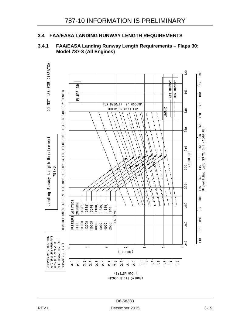
3.4 FAA/EASA LANDING RUNWAY LENGTH REQUIREMENTS .............. 3-19 3.4.1 FAA/EASA Landing Runway Length Requirements – Flaps 30:
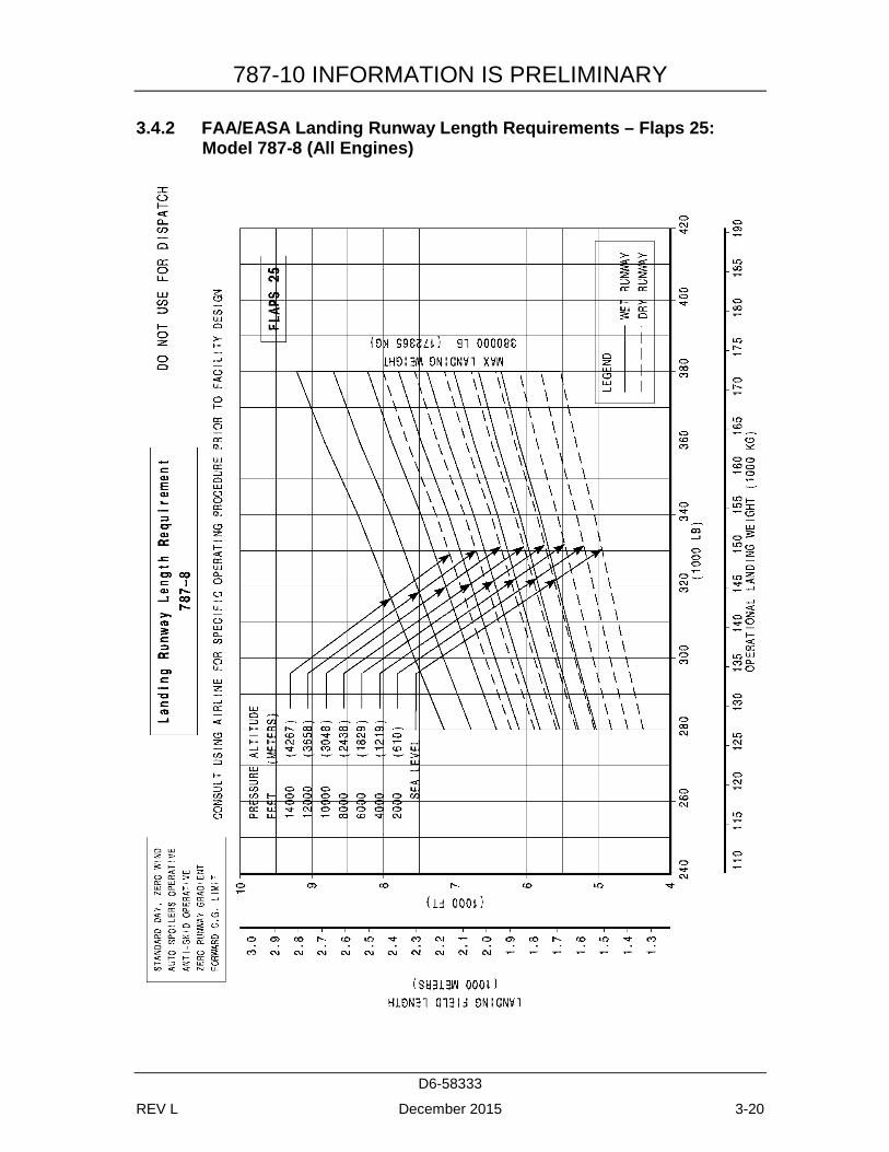
Model 787-8 (All Engines) .................................................................. 3-19 3.4.2 FAA/EASA Landing Runway Length Requirements – Flaps 25:
Model 787-8 (All Engines) .................................................................. 3-20 3.4.3 FAA/EASA Landing Runway Length Requirements – Flaps 30:
Model 787-9 (All Engines) .................................................................. 3-22 3.4.4 FAA/EASA Landing Runway Length Requirements – Flaps 25:
Model 787-9 (All Engines) .................................................................. 3-23 3.4.5 FAA/EASA Landing Runway Length Requirements: Model 787-
10 (All Engines) ................................................................................... 3-24
4.0 GROUND MANEUVERING .............................................................................. 4-25 4.1 GENERAL INFORMATION ......................................................................... 4-25 4.2 TURNING RADII .......................................................................................... 4-26
4.2.1 Turning Radii – No Slip Angle: Model 787-8 ..................................... 4-26 4.2.2 Turning Radii – No Slip Angle: Model 787-9 ..................................... 4-27 4.2.3 Turning Radii – No Slip Angle: Model 787-10 ................................... 4-28
4.3 CLEARANCE RADII: MODEL 787-8, 787-9, 787-10 ................................. 4-29 4.4 VISIBILITY FROM COCKPIT IN STATIC POSITION.............................. 4-30
4.4.1 Visibility from Cockpit in Static Position: Model 787-8, 787-9, 787-10 .................................................................................................. 4-30
4.5 RUNWAY AND TAXIWAY TURNPATHS ................................................ 4-31 4.5.1 Runway and Taxiway Turnpaths - Runway-to-Taxiway, More
Than 90 Degree Turn: Model 787-8 .................................................... 4-31 4.5.2 Runway and Taxiway Turnpaths - Runway-to-Taxiway, 90
Degree Turn: Model 787-8 ................................................................... 4-32 4.5.3 Runway and Taxiway Turnpaths - Taxiway-to-Taxiway, 90
Degree Turn: Model 787-8 ................................................................... 4-33 4.5.4 Runway and Taxiway Turnpaths - Runway-to-Taxiway, More
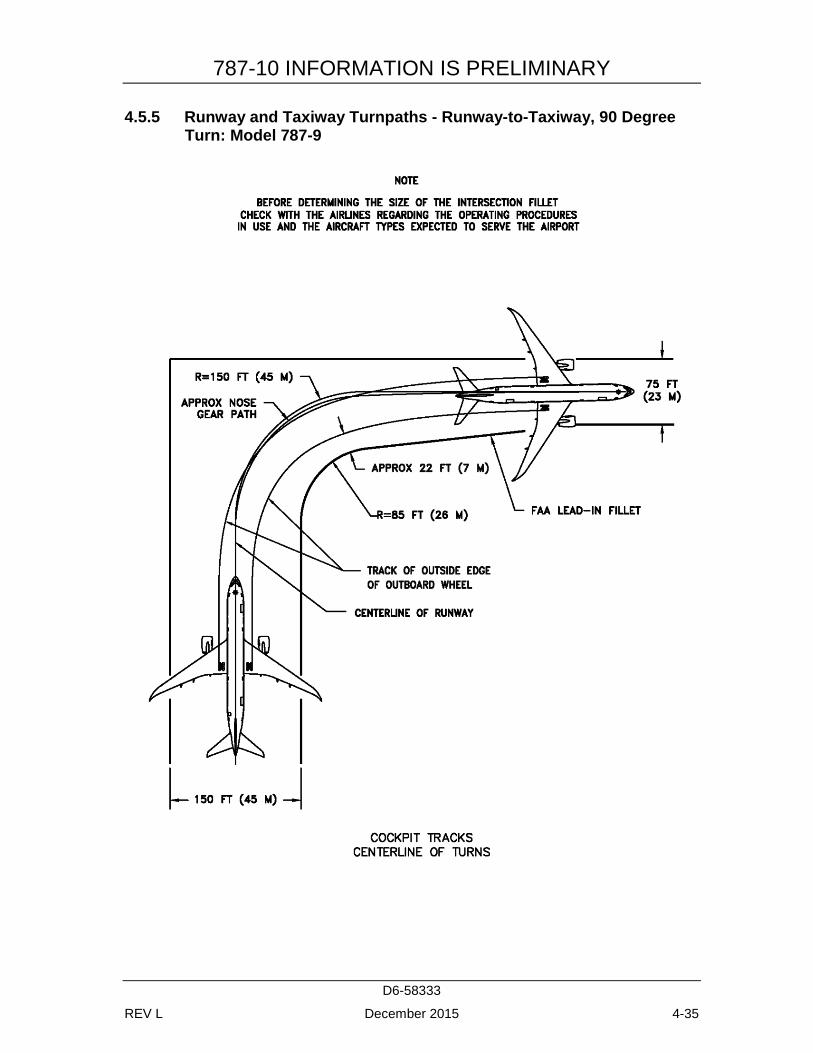
Than 90 Degree Turn: Model 787-9 .................................................... 4-34 4.5.5 Runway and Taxiway Turnpaths - Runway-to-Taxiway, 90
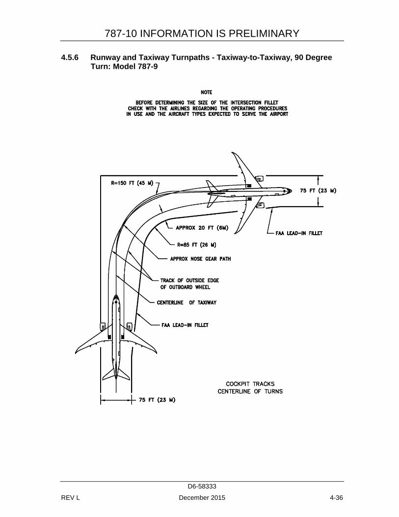
Degree Turn: Model 787-9 ................................................................... 4-35 4.5.6 Runway and Taxiway Turnpaths - Taxiway-to-Taxiway, 90
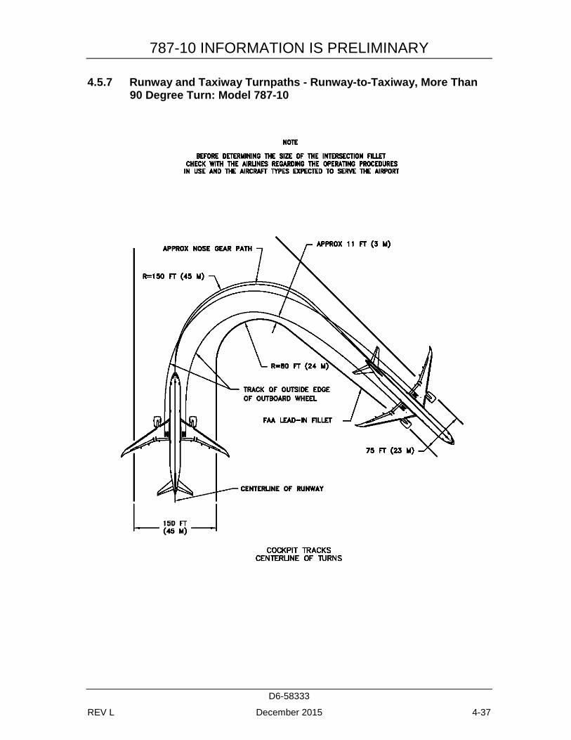
Degree Turn: Model 787-9 ................................................................... 4-36 4.5.7 Runway and Taxiway Turnpaths - Runway-to-Taxiway, More
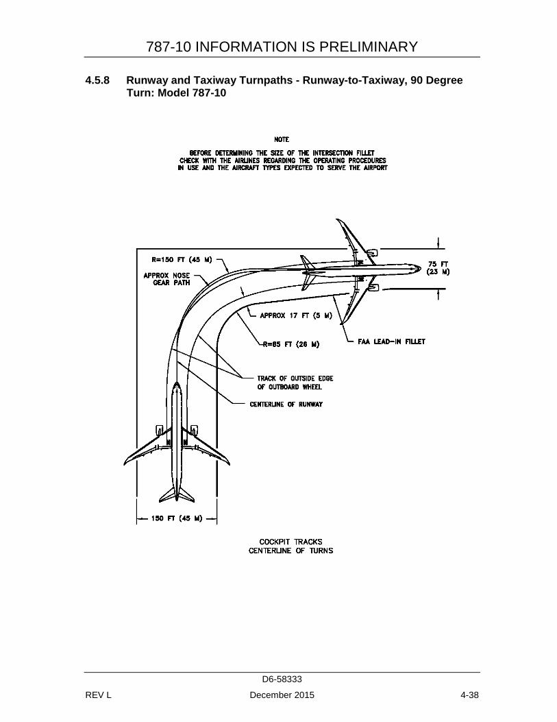
Than 90 Degree Turn: Model 787-10 .................................................. 4-37 4.5.8 Runway and Taxiway Turnpaths - Runway-to-Taxiway, 90
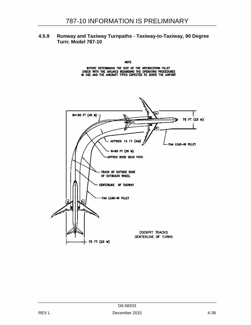
Degree Turn: Model 787-10 ................................................................. 4-38 4.5.9 Runway and Taxiway Turnpaths - Taxiway-to-Taxiway, 90
Degree Turn: Model 787-10 ................................................................. 4-39
787-10 INFORMATION IS PRELIMINARY
D6-58333
REV L December 2015 vii
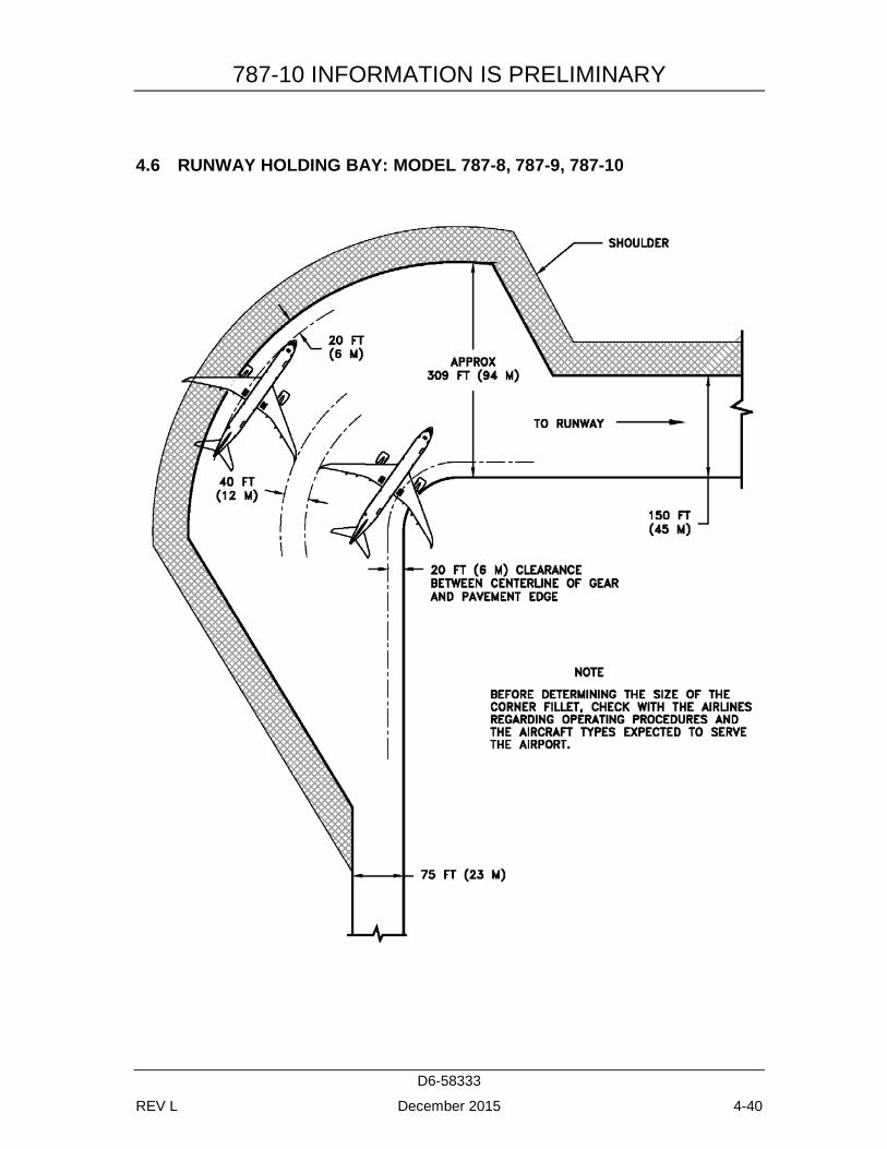
4.6 RUNWAY HOLDING BAY: MODEL 787-8, 787-9, 787-10 ...................... 4-40
5.0 TERMINAL SERVICING ..................................................................................... 5-1 5.1 AIRPLANE SERVICING ARRANGEMENT - TYPICAL
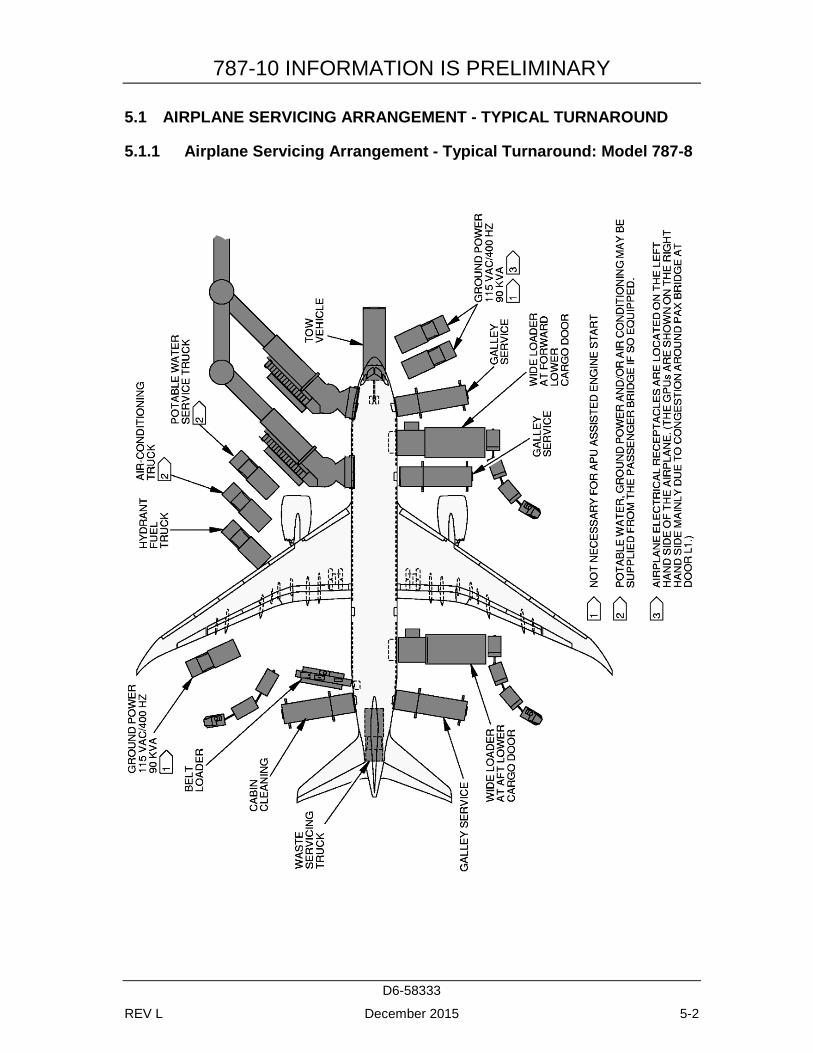
TURNAROUND .............................................................................................. 5-2 5.1.1 Airplane Servicing Arrangement - Typical Turnaround: Model
787-8 ...................................................................................................... 5-2 5.1.2 Airplane Servicing Arrangement - Typical Turnaround: Model
787-9 ...................................................................................................... 5-3 5.1.3 Airplane Servicing Arrangement - Typical Turnaround: Model
787-10 .................................................................................................... 5-4 5.1.4 Airplane Servicing Arrangement - Typical En Route: Model 787-
8 .............................................................................................................. 5-5 5.1.5 Airplane Servicing Arrangement - Typical En Route: Model 787-
9 .............................................................................................................. 5-6 5.1.6 Airplane Servicing Arrangement - Typical En Route: Model 787-
10 ............................................................................................................ 5-7 5.2 TERMINAL OPERATIONS - TURNAROUND STATION .......................... 5-8
5.2.1 Terminal Operations, Turntime Analysis - Turnaround Station: Model 787-8 ........................................................................................... 5-8
5.2.2 Terminal Operations, Turntime Analysis - Turnaround Station: Model 787-9 ........................................................................................... 5-9
5.2.3 Terminal Operations, Turntime Analysis - Turnaround Station: Model 787-10 ....................................................................................... 5-10
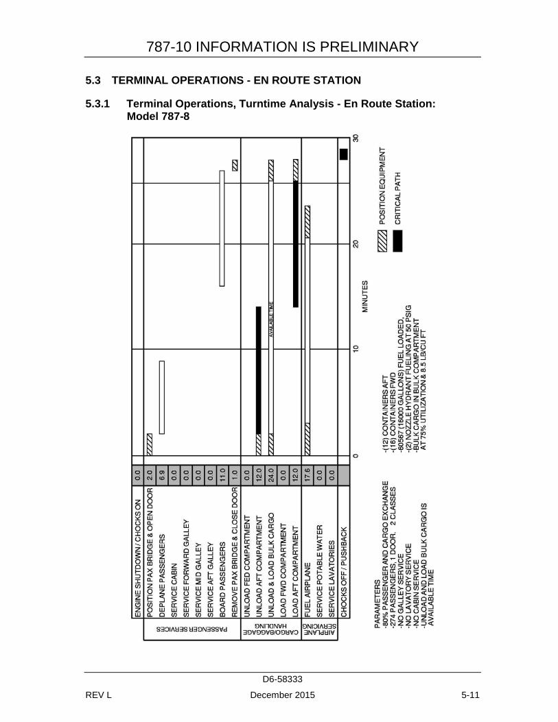
5.3 TERMINAL OPERATIONS - EN ROUTE STATION ................................. 5-11 5.3.1 Terminal Operations, Turntime Analysis - En Route Station:
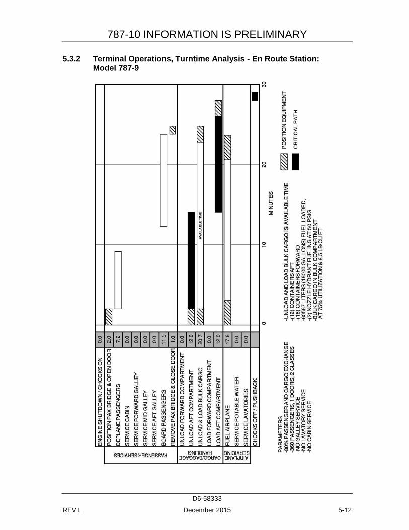
Model 787-8 ......................................................................................... 5-11 5.3.2 Terminal Operations, Turntime Analysis - En Route Station:
Model 787-9 ......................................................................................... 5-12 5.3.3 Terminal Operations, Turntime Analysis - En Route Station:
Model 787-10 ....................................................................................... 5-13 5.4 GROUND SERVICE CONNECTIONS ........................................................ 5-14
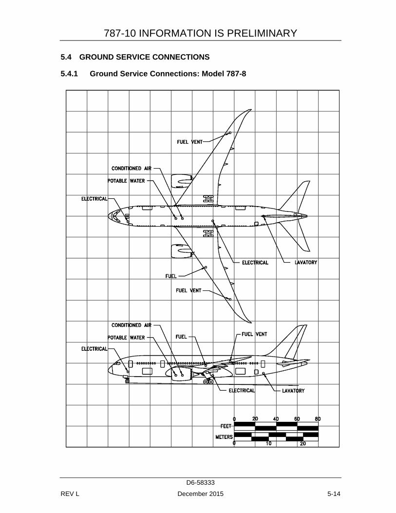
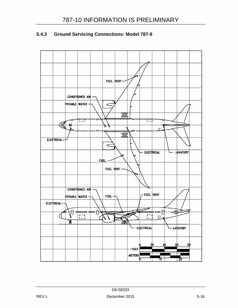
5.4.1 Ground Service Connections: Model 787-8 ......................................... 5-14 5.4.2 Ground Service Connections and Capacities: Model 787-8 ................ 5-15 5.4.3 Ground Servicing Connections: Model 787-9 ..................................... 5-16 5.4.4 Ground Servicing Connections and Capacities: Model 787-9 ............. 5-17 5.4.5 Ground Servicing Connections: Model 787-10 ................................... 5-18 5.4.6 Ground Servicing Connections and Capacities: Model 787-10 ........... 5-19
5.5 ENGINE STARTING AND GROUND POWER REQUIREMENTS .......... 5-20 5.5.1 Engine Starting Ground Power Requirements – Electrical – APU:
Model 787-8, 787-9, 787-10 ................................................................ 5-20 5.5.2 Engine Starting Ground Power Requirements – Electrical – APU
Inoperative – Two/Three GPU: Model 787-8, 787-9, 787-10 ............. 5-21
787-10 INFORMATION IS PRELIMINARY
D6-58333
REV L December 2015 viii
5.5.3 Engine Power Requirements – Pneumatic: Model 787-8, 787-9, 787-10 .................................................................................................. 5-22
5.6 CONDITIONED AIR REQUIREMENTS ..................................................... 5-23 5.6.1 Conditioned Air Flow Requirements – Cooling Time: Model 787-
8 ............................................................................................................ 5-23 5.6.2 Conditioned Air Flow Requirements – Cooling – Steady State
(103 F Ambient Air): Model 787-8 ...................................................... 5-24 5.6.3 Conditioned Air Flow Requirements – Cooling – Steady State
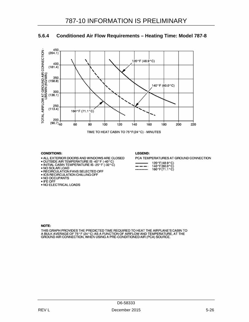
(80 F Ambient Air): Model 787-8 ........................................................ 5-25 5.6.4 Conditioned Air Flow Requirements – Heating Time: Model 787-
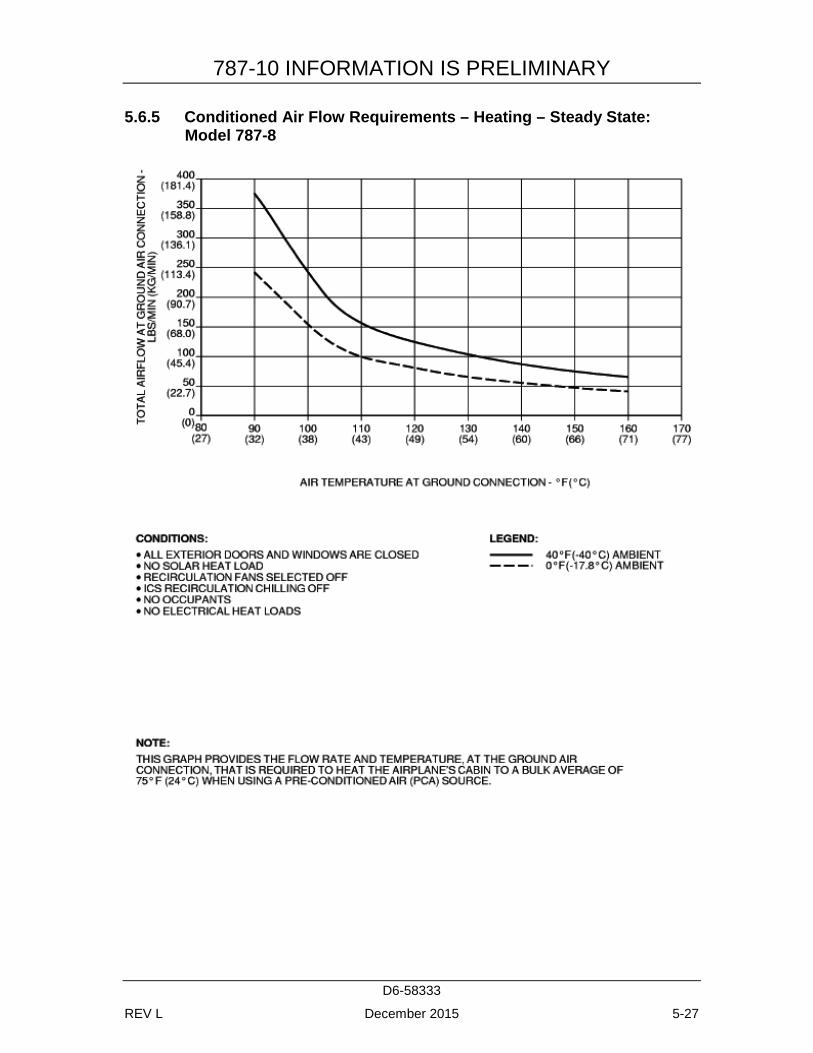
8 ............................................................................................................ 5-26 5.6.5 Conditioned Air Flow Requirements – Heating – Steady State:
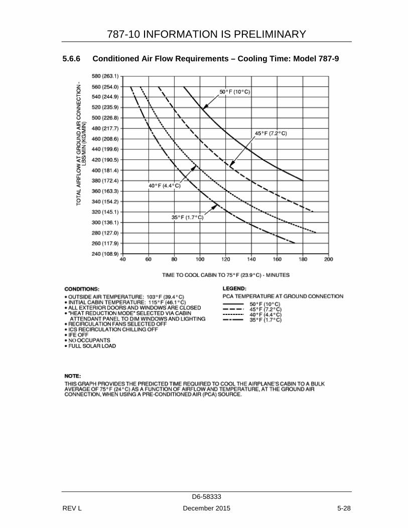
Model 787-8 ......................................................................................... 5-27 5.6.6 Conditioned Air Flow Requirements – Cooling Time: Model 787-
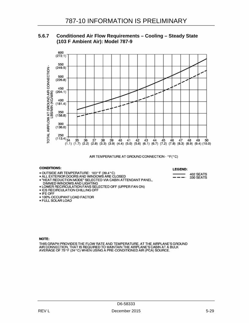
9 ............................................................................................................ 5-28 5.6.7 Conditioned Air Flow Requirements – Cooling – Steady State
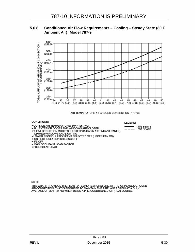
(103 F Ambient Air): Model 787-9 ...................................................... 5-29 5.6.8 Conditioned Air Flow Requirements – Cooling – Steady State
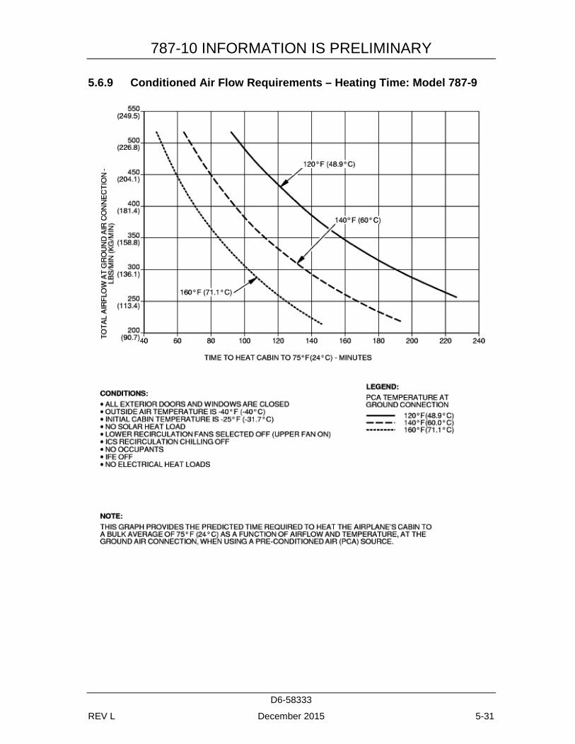
(80 F Ambient Air): Model 787-9 ........................................................ 5-30 5.6.9 Conditioned Air Flow Requirements – Heating Time: Model 787-
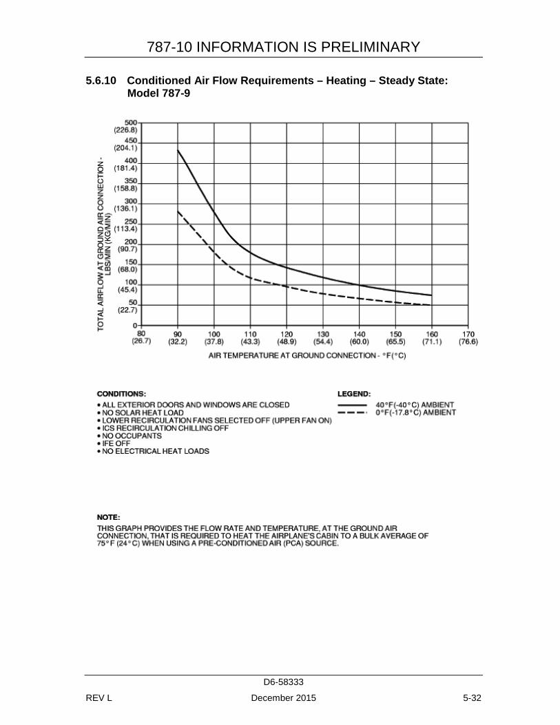
9 ............................................................................................................ 5-31 5.6.10 Conditioned Air Flow Requirements – Heating – Steady State:
Model 787-9 ......................................................................................... 5-32 5.6.11 Conditioned Air Flow Requirements: Model 787-10 .......................... 5-33
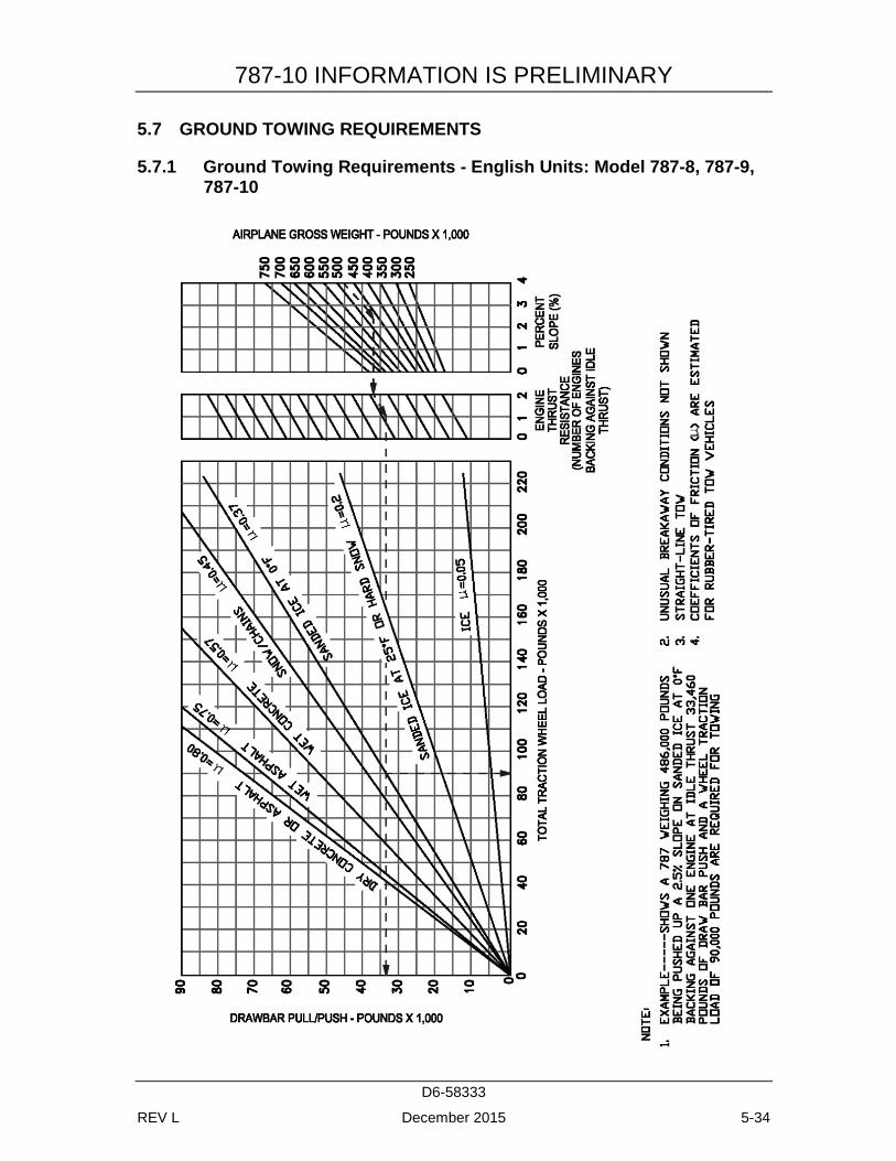
5.7 GROUND TOWING REQUIREMENTS ...................................................... 5-34 5.7.1 Ground Towing Requirements - English Units: Model 787-8, 787-
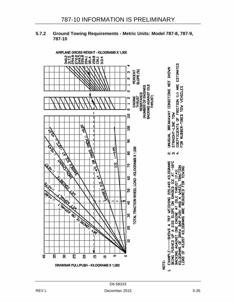
9, 787-10 .............................................................................................. 5-34 5.7.2 Ground Towing Requirements - Metric Units: Model 787-8, 787-
9, 787-10 .............................................................................................. 5-35
6.0 JET ENGINE WAKE AND NOISE DATA .......................................................... 6-1 6.1 JET ENGINE EXHAUST VELOCITIES AND TEMPERATURE ................ 6-1
6.1.1 Jet Engine Exhaust Velocity Contours – Idle Thrust: Model 787-8 ...... 6-2 6.1.2 Jet Engine Exhaust Velocity Contours - Breakaway Thrust / 0%
Slope: Model 787-8 ................................................................................ 6-3 6.1.3 Jet Engine Exhaust Velocity Contours – Breakaway Thrust / 1%
Slope / Both Engines / MTW: Model 787-8 .......................................... 6-4 6.1.4 Jet Engine Exhaust Velocity Contours – Breakaway Thrust / 0%
Slope / Single Engine / MTW: Model 787-8 ......................................... 6-5 6.1.5 Jet Engine Exhaust Velocity Contours – Breakaway Thrust / 0%
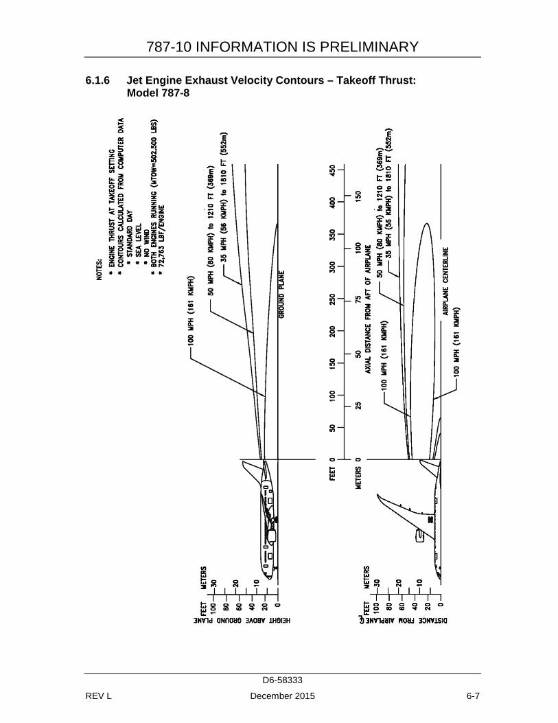
Slope / Single Engine / MLW: Model 787-8 ......................................... 6-6 6.1.6 Jet Engine Exhaust Velocity Contours – Takeoff Thrust:
Model 787-8 ........................................................................................... 6-7
787-10 INFORMATION IS PRELIMINARY
D6-58333
REV L December 2015 ix
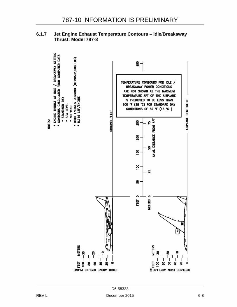
6.1.7 Jet Engine Exhaust Temperature Contours – Idle/Breakaway Thrust: Model 787-8 .............................................................................. 6-8
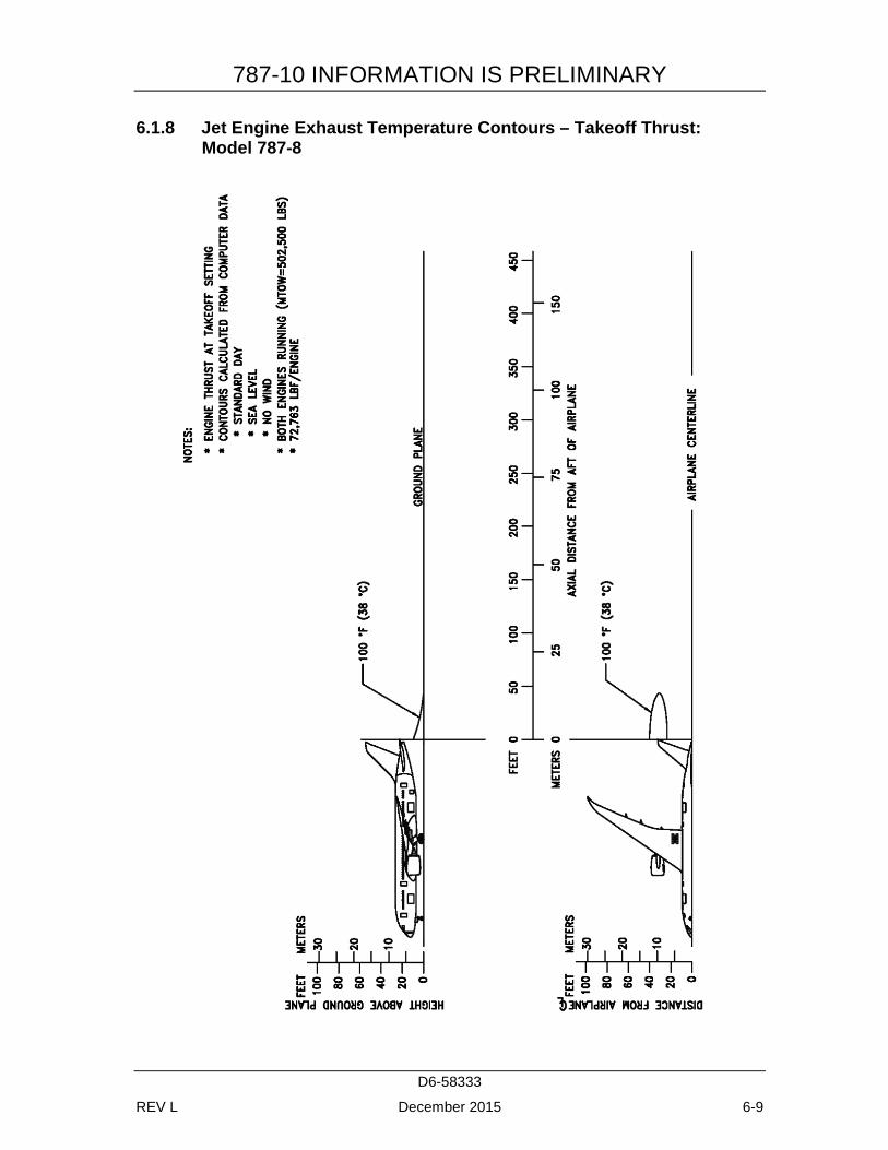
6.1.8 Jet Engine Exhaust Temperature Contours – Takeoff Thrust: Model 787-8 ........................................................................................... 6-9
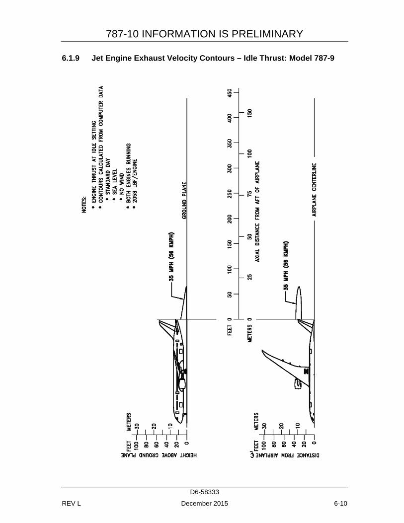
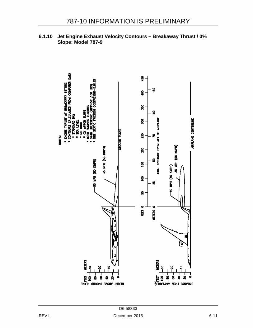
6.1.9 Jet Engine Exhaust Velocity Contours – Idle Thrust: Model 787-9 .... 6-10 6.1.10 Jet Engine Exhaust Velocity Contours – Breakaway Thrust / 0%
Slope: Model 787-9 .............................................................................. 6-11 6.1.11 Jet Engine Exhaust Velocity Contours – Breakaway Thrust / 1%
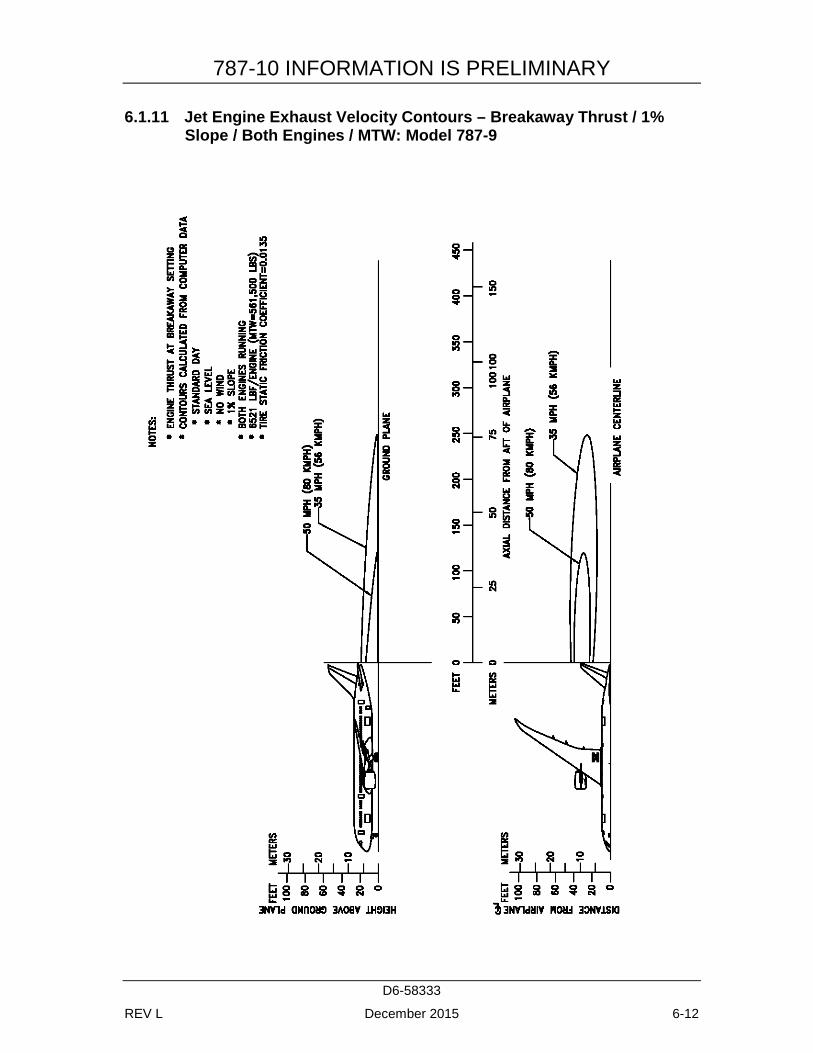
Slope / Both Engines / MTW: Model 787-9 ........................................ 6-12 6.1.12 Jet Engine Exhaust Velocity Contours – Breakaway Thrust / 0%
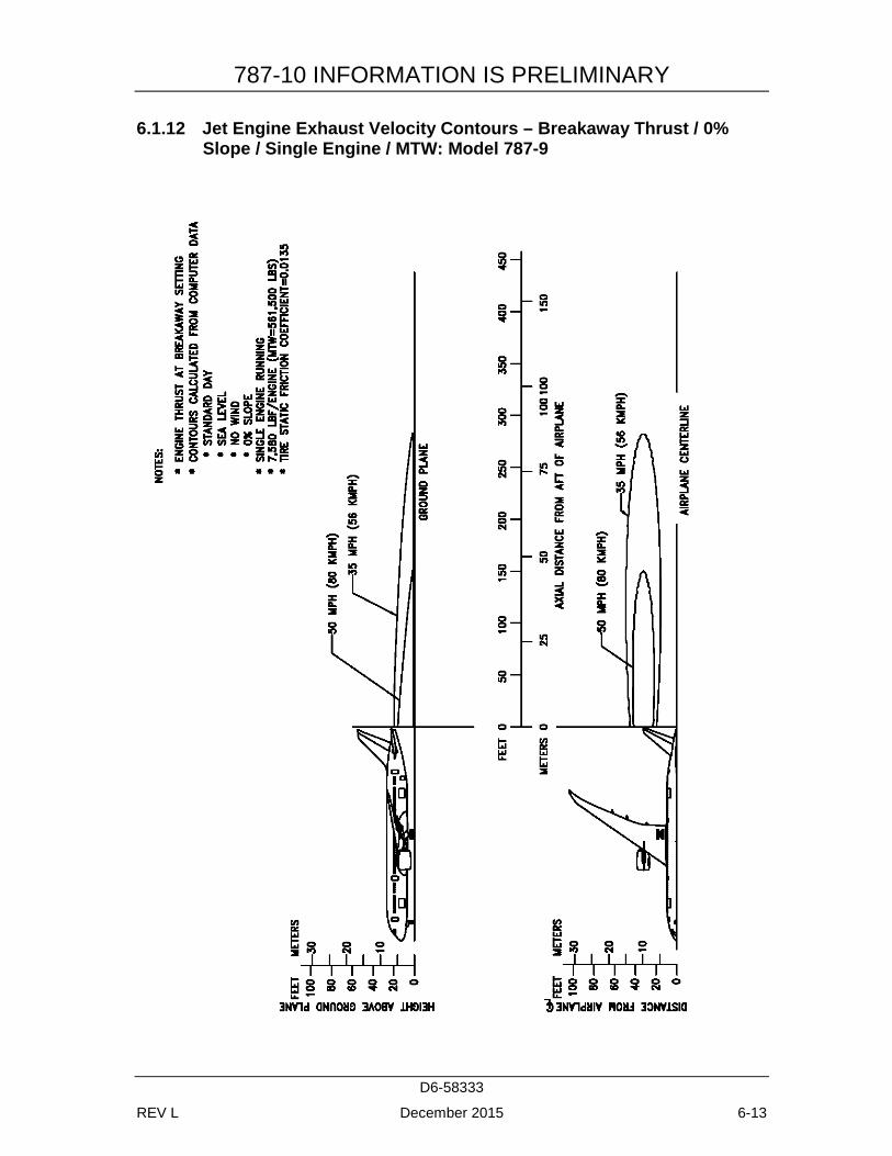
Slope / Single Engine / MTW: Model 787-9 ....................................... 6-13 6.1.13 Jet Engine Exhaust Velocity Contours – Breakaway Thrust / 0%
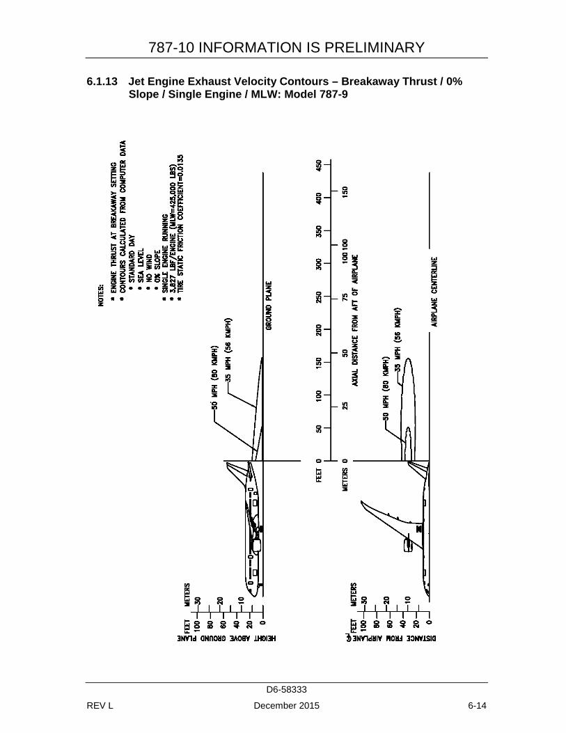
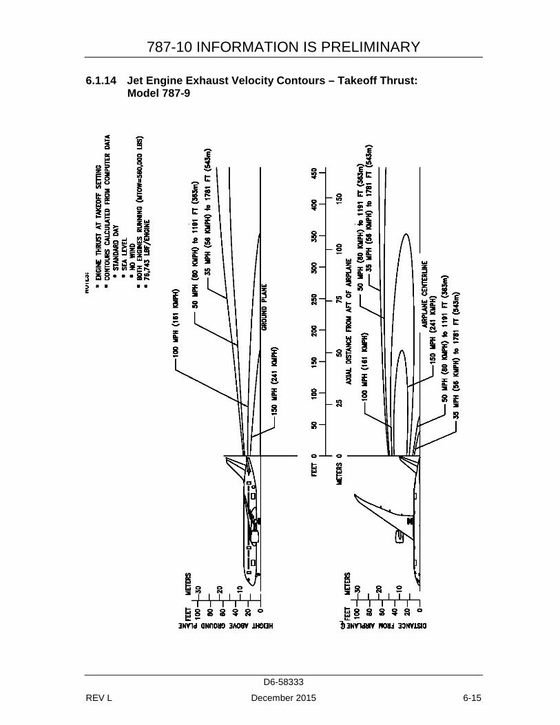
Slope / Single Engine / MLW: Model 787-9 ....................................... 6-14 6.1.14 Jet Engine Exhaust Velocity Contours – Takeoff Thrust:
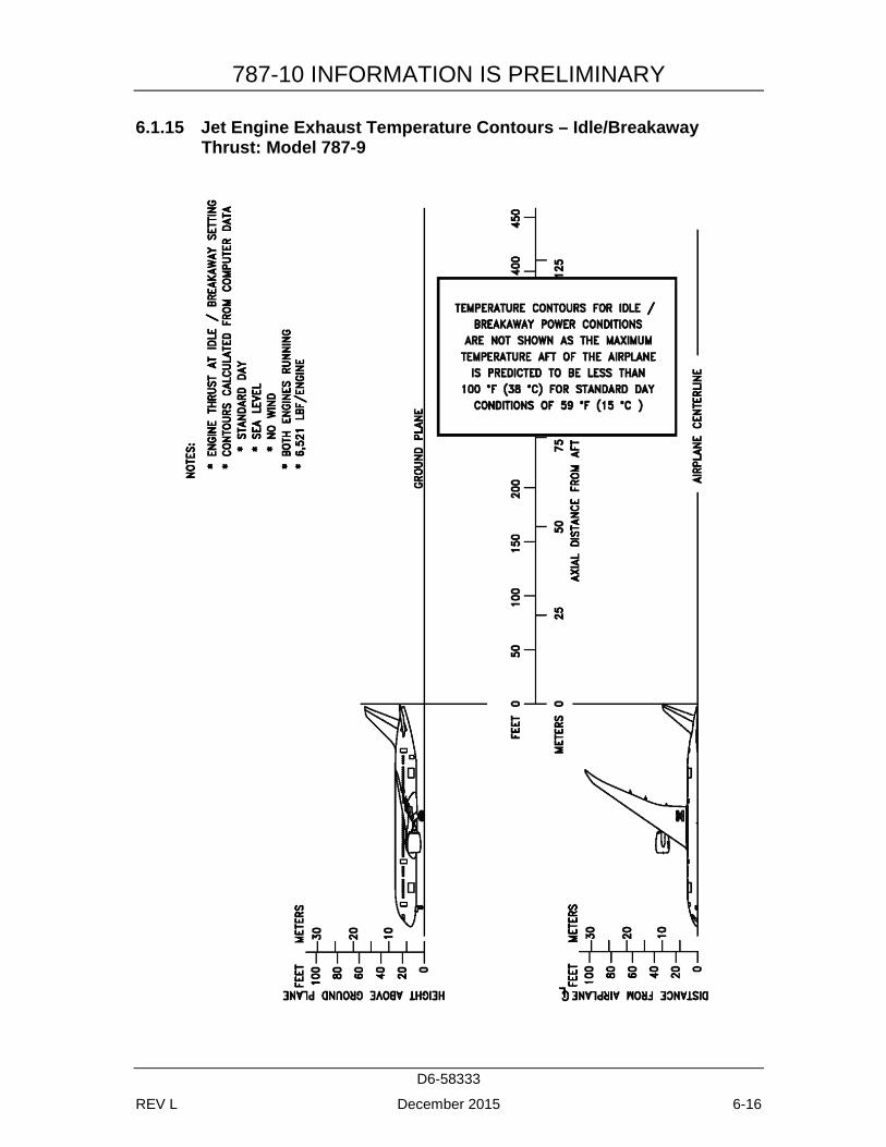
Model 787-9 ......................................................................................... 6-15 6.1.15 Jet Engine Exhaust Temperature Contours – Idle/Breakaway
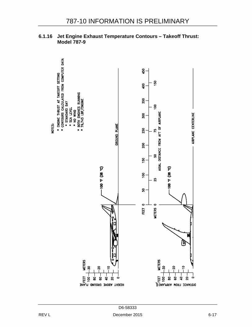
Thrust: Model 787-9 ............................................................................ 6-16 6.1.16 Jet Engine Exhaust Temperature Contours – Takeoff Thrust:
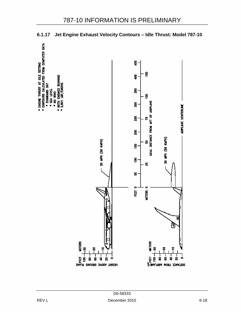
Model 787-9 ......................................................................................... 6-17 6.1.17 Jet Engine Exhaust Velocity Contours – Idle Thrust: Model 787-
10 .......................................................................................................... 6-18 6.1.18 Jet Engine Exhaust Velocity Contours – Breakaway Thrust / 0%
Slope: Model 787-10 ............................................................................ 6-19 6.1.19 Jet Engine Exhaust Velocity Contours – Breakaway Thrust / 1%
Slope / Both Engines / MTW: Model 787-10 ...................................... 6-20 6.1.20 Jet Engine Exhaust Velocity Contours – Breakaway Thrust / 0%
Slope / Single Engine / MTW: Model 787-10 ..................................... 6-21 6.1.21 Jet Engine Exhaust Velocity Contours – Breakaway Thrust / 0%
Slope / Single Engine / MLW: Model 787-10 ..................................... 6-22 6.1.22 Jet Engine Exhaust Velocity Contours – Takeoff Thrust:
Model 787-10 ....................................................................................... 6-23 6.1.23 Jet Engine Exhaust Temperature Contours – Idle/Breakaway
Thrust: Model 787-10 .......................................................................... 6-24 6.1.24 Jet Engine Exhaust Temperature Contours – Takeoff Thrust:
Model 787-10 ....................................................................................... 6-25 6.2 AIRPORT AND COMMUNITY NOISE ....................................................... 6-26
7.0 PAVEMENT DATA .............................................................................................. 7-1 7.1 GENERAL INFORMATION ........................................................................... 7-1 7.2 LANDING GEAR FOOTPRINT: MODEL 787-8, 787-9, 787-10 .................. 7-4 7.3 MAXIMUM PAVEMENT LOADS: MODEL 787-8, 787-9, 787-10 ............. 7-5 7.4 LANDING GEAR LOADING ON PAVEMENT ........................................... 7-6
7.4.1 Landing Gear Loading on Pavement: Model 787-8 ............................... 7-6
787-10 INFORMATION IS PRELIMINARY
D6-58333
REV L December 2015 x
7.4.2 Landing Gear Loading on Pavement: Model 787-9 ............................... 7-7 7.4.3 Landing Gear Loading on Pavement: Model 787-10 ............................. 7-8
7.5 FLEXIBLE PAVEMENT REQUIREMENTS - U.S. ARMY CORPS OF ENGINEERS METHOD S-77-1 ...................................................................... 7-9
7.5.1 Flexible Pavement Requirements - U.S. Army Corps of Engineers Design Method (S-77-1): Model 787-8 ................................................ 7-10
7.5.2 Flexible Pavement Requirements - U.S. Army Corps of Engineers Design Method (S-77-1): Model 787-9 ................................................ 7-11
7.5.3 Flexible Pavement Requirements - U.S. Army Corps of Engineers Design Method (S-77-1): Model 787-10 .............................................. 7-12
7.6 FLEXIBLE PAVEMENT REQUIREMENTS - LCN METHOD ................. 7-13 7.7 RIGID PAVEMENT REQUIREMENTS - PORTLAND CEMENT
ASSOCIATION DESIGN METHOD ............................................................ 7-14 7.7.1 Rigid Pavement Requirements - Portland Cement Association
Design Method: Model 787-8 .............................................................. 7-15 7.7.2 Rigid Pavement Requirements - Portland Cement Association
Design Method: Model 787-9 .............................................................. 7-16 7.7.3 Rigid Pavement Requirements - Portland Cement Association
Design Method: Model 787-10 ............................................................ 7-17 7.8 RIGID PAVEMENT REQUIREMENTS - LCN CONVERSION ................ 7-18 7.9 RIGID PAVEMENT REQUIREMENTS - FAA DESIGN METHOD ........ 7-19 7.10 ACN/PCN REPORTING SYSTEM - FLEXIBLE AND RIGID
PAVEMENTS ................................................................................................ 7-20 7.10.1 Aircraft Classification Number - Flexible Pavement: Model 787-8 .... 7-21 7.10.2 Aircraft Classification Number - Flexible Pavement: Model 787-9 .... 7-22 7.10.3 Aircraft Classification Number - Flexible Pavement: Model 787-
10 .......................................................................................................... 7-23 7.10.4 Aircraft Classification Number - Rigid Pavement: Model 787-8 ........ 7-24 7.10.5 Aircraft Classification Number – Rigid Pavement: Model 787-9 ....... 7-25 7.10.6 Aircraft Classification Number – Rigid Pavement: Model 787-10 ..... 7-26
8.0 FUTURE 787 DERIVATIVE AIRPLANES.......................................................... 8-1
9.0 scaled 787 DRAWINGS ......................................................................................... 9-2 9.1 MODEL 787-8 .................................................................................................. 9-3
9.1.1 Scaled Drawings – 1:500: Model 787-8 ................................................. 9-3 9.1.2 Scaled Drawings – 1:500: Model 787-8 ................................................. 9-4
9.2 MODEL 787-9 .................................................................................................. 9-5 9.2.1 Scaled Drawing – 1:500: Model 787-9 .................................................. 9-5 9.2.2 Scaled Drawing – 1:500: Model 787-9 .................................................. 9-6
9.3 MODEL 787-10 ................................................................................................ 9-7 9.3.1 Scaled Drawings – 1:500: Model 787-10 ............................................... 9-7 9.3.2 Scaled Drawings – 1:500: Model 787-10 ............................................... 9-8

787-10 INFORMATION IS PRELIMINARY
D6-58333
REV L December 2015 xi
787-10 INFORMATION IS PRELIMINARY
D6-58333
REV L December 2015 1-1
1.0 SCOPE AND INTRODUCTION
1.1 SCOPE
This document provides, in a standardized format, airplane characteristics data for general airport planning. Since operational practices vary among airlines, specific data should be coordinated with the using airlines prior to facility design. Boeing Commercial Airplanes should be contacted for any additional information required.
Content of the document reflects the results of a coordinated effort by representatives from the following organizations:
• Aerospace Industries Association
• Airports Council International - North America
• Air Transport Association of America
• International Air Transport Association
The airport planner may also want to consider the information presented in the "Commercial Aircraft Design Characteristics - Trends and Growth Projections," for long range planning needs and can be accessed via the following website:
http://www.boeing.com/airports
The document is updated periodically and represents the coordinated efforts of the following organizations regarding future aircraft growth trends.
• International Coordinating Council of Aerospace Industries Associations
• Airports Council International - North American and World Organizations
• Air Transport Association of America
• International Air Transport Association
787-10 INFORMATION IS PRELIMINARY
D6-58333
REV L December 2015 1-2
1.2 INTRODUCTION
This document conforms to NAS 3601. It provides characteristics of the Boeing 787 Dreamliner family of airplanes for airport planners and operators, airlines, architectural and engineering consultant organizations, and other interested industry agencies. Airplane changes and available options may alter model characteristics. The data presented herein reflects the 787 family. Data used is generic in scope and not customer-specific.
For additional information contact:
Boeing Commercial Airplanes 2201 Seal Beach Blvd. M/C: 110-SB02 Seal Beach, CA 90740-1515 U.S.A.
Attention: Manager, Airport Compatibility Engineering
Phone: 562-797-1172 Email: [email protected]
787-10 INFORMATION IS PRELIMINARY
D6-58333
REV L December 2015 1-3
1.3 A BRIEF DESCRIPTION OF THE 787 FAMILY OF AIRPLANES
The 787 Dreamliner is a super-efficient family of twin-engine airplanes with exceptional environmental performance and new passenger-pleasing features. An international team of aerospace companies builds the 787, led by Boeing at its Everett facility near Seattle, WA and in North Charleston, SC.
787 Family
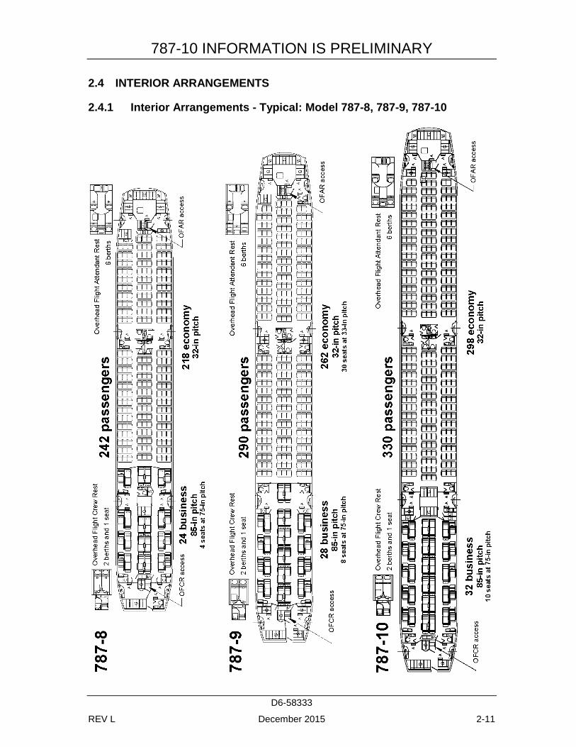
The 787 family is designed for medium- to long-range flights. In a typical dual-class configuration, the 787-8 can carry 242 passengers, the 787-9 can carry 290 passengers, and the 787-10 will carry 330 passengers.
787 Engines
The 787 features new engines from General Electric and Rolls-Royce that represent nearly a two-generation jump in technology.
Cargo Handling
The lower lobe cargo compartments can accommodate a variety of containers and pallets now in use.
Ground Servicing
The 787 features a more-electric design and does not have a traditional pneumatic system. The traditional pneumatic starters on the engines are replaced with a pair of gearbox-mounted main-engine starter/generators. Cabin air conditioning and wing anti-ice systems are also electrically driven. The remaining pneumatic system is for engine nacelle anti-ice. The airplane has ground service connections compatible with existing ground service equipment, and no special equipment is necessary. In case of an inoperable APU, engine starts may be accomplished via the airplane's external ground electrical connections.
787-10 INFORMATION IS PRELIMINARY
D6-58333
REV L December 2015 2-1
2.0 AIRPLANE DESCRIPTION
2.1 GENERAL CHARACTERISTICS
Maximum Design Taxi Weight (MTW). Maximum weight for ground maneuver as limited by aircraft strength and airworthiness requirements. (It includes weight of taxi and run-up fuel.)
Maximum Design Takeoff Weight (MTOW). Maximum weight for takeoff as limited by aircraft strength and airworthiness requirements. (This is the maximum weight at start of the takeoff run.)
Maximum Design Landing Weight (MLW). Maximum weight for landing as limited by aircraft strength and airworthiness requirements.
Maximum Design Zero Fuel Weight (MZFW). Maximum weight allowed before usable fuel and other specified usable agents must be loaded in defined sections of the aircraft as limited by strength and airworthiness requirements.
Operating Empty Weight (OEW). Weight of structure, powerplant, furnishing systems, unusable fuel and other unusable propulsion agents, and other items of equipment that are considered an integral part of a particular airplane configuration. Also included are certain standard items, personnel, equipment, and supplies necessary for full operations, excluding usable fuel and payload.
Maximum Structural Payload. Maximum design zero fuel weight minus operation empty weight.
Maximum Seating Capacity. The maximum number of passengers specifically certificated or anticipated for certification.
Maximum Cargo Volume. The maximum space available for cargo.
Usable Fuel. Fuel available for aircraft propulsion.
787-10 INFORMATION IS PRELIMINARY
D6-58333
REV L December 2015 2-2
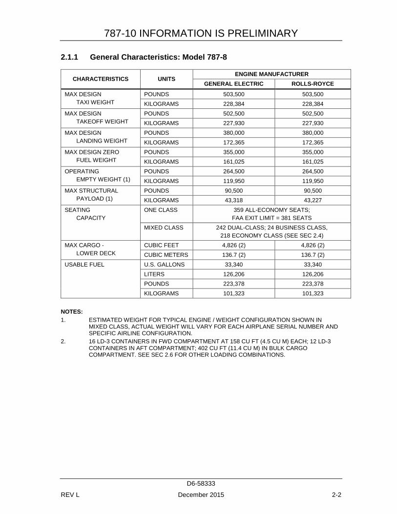
2.1.1 General Characteristics: Model 787-8
CHARACTERISTICS UNITS ENGINE MANUFACTURER
GENERAL ELECTRIC ROLLS-ROYCE
MAX DESIGN TAXI WEIGHT
POUNDS 503,500 503,500 KILOGRAMS 228,384 228,384
MAX DESIGN TAKEOFF WEIGHT
POUNDS 502,500 502,500 KILOGRAMS 227,930 227,930
MAX DESIGN LANDING WEIGHT
POUNDS 380,000 380,000 KILOGRAMS 172,365 172,365
MAX DESIGN ZERO FUEL WEIGHT
POUNDS 355,000 355,000 KILOGRAMS 161,025 161,025
OPERATING EMPTY WEIGHT (1)
POUNDS 264,500 264,500 KILOGRAMS 119,950 119,950
MAX STRUCTURAL PAYLOAD (1)
POUNDS 90,500 90,500 KILOGRAMS 43,318 43,227
SEATING CAPACITY
ONE CLASS 359 ALL-ECONOMY SEATS; FAA EXIT LIMIT = 381 SEATS
MIXED CLASS 242 DUAL-CLASS; 24 BUSINESS CLASS, 218 ECONOMY CLASS (SEE SEC 2.4)
MAX CARGO - LOWER DECK
CUBIC FEET 4,826 (2) 4,826 (2) CUBIC METERS 136.7 (2) 136.7 (2)
USABLE FUEL U.S. GALLONS 33,340 33,340 LITERS 126,206 126,206 POUNDS 223,378 223,378 KILOGRAMS 101,323 101,323
NOTES: 1. ESTIMATED WEIGHT FOR TYPICAL ENGINE / WEIGHT CONFIGURATION SHOWN IN
MIXED CLASS, ACTUAL WEIGHT WILL VARY FOR EACH AIRPLANE SERIAL NUMBER AND SPECIFIC AIRLINE CONFIGURATION.
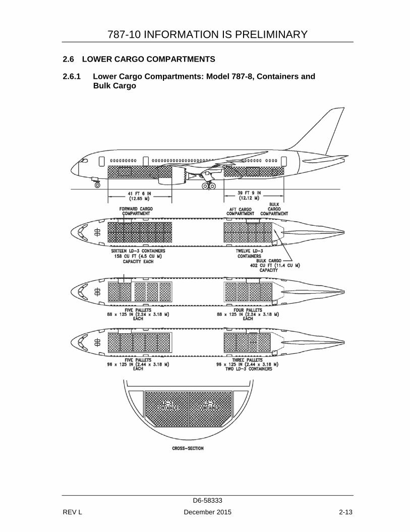
2. 16 LD-3 CONTAINERS IN FWD COMPARTMENT AT 158 CU FT (4.5 CU M) EACH; 12 LD-3 CONTAINERS IN AFT COMPARTMENT; 402 CU FT (11.4 CU M) IN BULK CARGO COMPARTMENT. SEE SEC 2.6 FOR OTHER LOADING COMBINATIONS.
787-10 INFORMATION IS PRELIMINARY
D6-58333
REV L December 2015 2-3
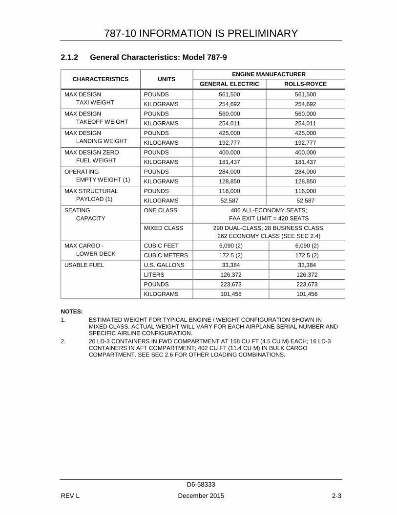
2.1.2 General Characteristics: Model 787-9
CHARACTERISTICS UNITS ENGINE MANUFACTURER
GENERAL ELECTRIC ROLLS-ROYCE
MAX DESIGN TAXI WEIGHT
POUNDS 561,500 561,500 KILOGRAMS 254,692 254,692
MAX DESIGN TAKEOFF WEIGHT
POUNDS 560,000 560,000 KILOGRAMS 254,011 254,011
MAX DESIGN LANDING WEIGHT
POUNDS 425,000 425,000 KILOGRAMS 192,777 192,777
MAX DESIGN ZERO FUEL WEIGHT
POUNDS 400,000 400,000 KILOGRAMS 181,437 181,437
OPERATING EMPTY WEIGHT (1)
POUNDS 284,000 284,000 KILOGRAMS 128,850 128,850
MAX STRUCTURAL PAYLOAD (1)
POUNDS 116,000 116,000 KILOGRAMS 52,587 52,587
SEATING CAPACITY
ONE CLASS 406 ALL-ECONOMY SEATS; FAA EXIT LIMIT = 420 SEATS
MIXED CLASS 290 DUAL-CLASS; 28 BUSINESS CLASS, 262 ECONOMY CLASS (SEE SEC 2.4)
MAX CARGO - LOWER DECK
CUBIC FEET 6,090 (2) 6,090 (2) CUBIC METERS 172.5 (2) 172.5 (2)
USABLE FUEL U.S. GALLONS 33,384 33,384 LITERS 126,372 126,372 POUNDS 223,673 223,673 KILOGRAMS 101,456 101,456
NOTES: 1. ESTIMATED WEIGHT FOR TYPICAL ENGINE / WEIGHT CONFIGURATION SHOWN IN
MIXED CLASS, ACTUAL WEIGHT WILL VARY FOR EACH AIRPLANE SERIAL NUMBER AND SPECIFIC AIRLINE CONFIGURATION.
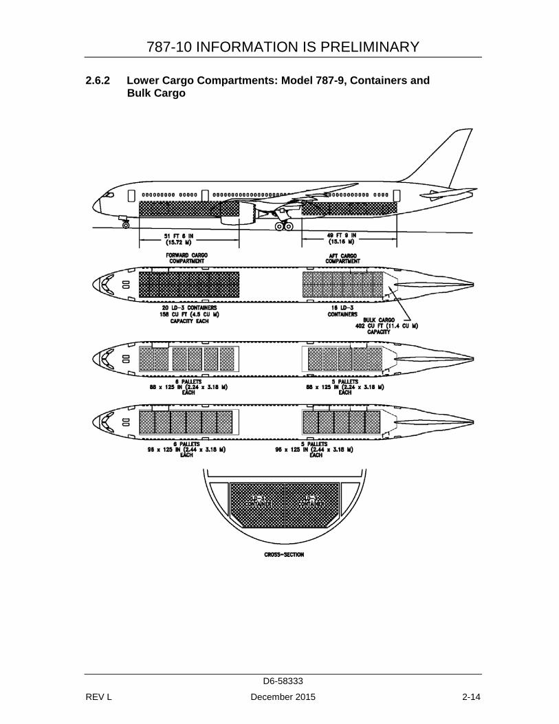
2. 20 LD-3 CONTAINERS IN FWD COMPARTMENT AT 158 CU FT (4.5 CU M) EACH; 16 LD-3 CONTAINERS IN AFT COMPARTMENT; 402 CU FT (11.4 CU M) IN BULK CARGO COMPARTMENT. SEE SEC 2.6 FOR OTHER LOADING COMBINATIONS.
787-10 INFORMATION IS PRELIMINARY
D6-58333
REV L December 2015 2-4
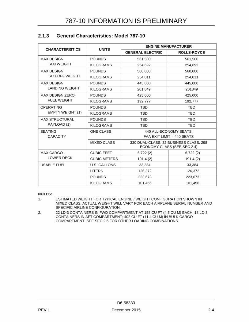
2.1.3 General Characteristics: Model 787-10
CHARACTERISTICS UNITS ENGINE MANUFACTURER
GENERAL ELECTRIC ROLLS-ROYCE
MAX DESIGN TAXI WEIGHT
POUNDS 561,500 561,500 KILOGRAMS 254,692 254,692
MAX DESIGN TAKEOFF WEIGHT
POUNDS 560,000 560,000 KILOGRAMS 254,011 254,011
MAX DESIGN LANDING WEIGHT
POUNDS 445,000 445,000 KILOGRAMS 201,849 201849
MAX DESIGN ZERO FUEL WEIGHT
POUNDS 425,000 425,000 KILOGRAMS 192,777 192,777
OPERATING EMPTY WEIGHT (1)
POUNDS TBD TBD KILOGRAMS TBD TBD
MAX STRUCTURAL PAYLOAD (1)
POUNDS TBD TBD KILOGRAMS TBD TBD
SEATING CAPACITY
ONE CLASS 440 ALL-ECONOMY SEATS; FAA EXIT LIMIT = 440 SEATS
MIXED CLASS 330 DUAL-CLASS; 32 BUSINESS CLASS, 298 ECONOMY CLASS (SEE SEC 2.4)
MAX CARGO - LOWER DECK
CUBIC FEET 6,722 (2) 6,722 (2) CUBIC METERS 191.4 (2) 191.4 (2)
USABLE FUEL U.S. GALLONS 33,384 33,384 LITERS 126,372 126,372 POUNDS 223,673 223,673 KILOGRAMS 101,456 101,456
NOTES: 1. ESTIMATED WEIGHT FOR TYPICAL ENGINE / WEIGHT CONFIGURATION SHOWN IN
MIXED CLASS, ACTUAL WEIGHT WILL VARY FOR EACH AIRPLANE SERIAL NUMBER AND SPECIFIC AIRLINE CONFIGURATION.
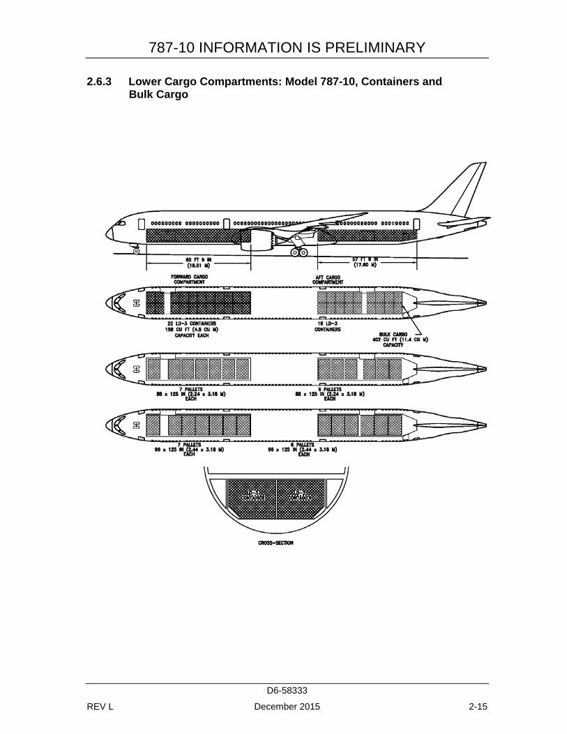
2. 22 LD-3 CONTAINERS IN FWD COMPARTMENT AT 158 CU FT (4.5 CU M) EACH; 18 LD-3 CONTAINERS IN AFT COMPARTMENT; 402 CU FT (11.4 CU M) IN BULK CARGO COMPARTMENT. SEE SEC 2.6 FOR OTHER LOADING COMBINATIONS.
787-10 INFORMATION IS PRELIMINARY
D6-58333
REV L December 2015 2-5
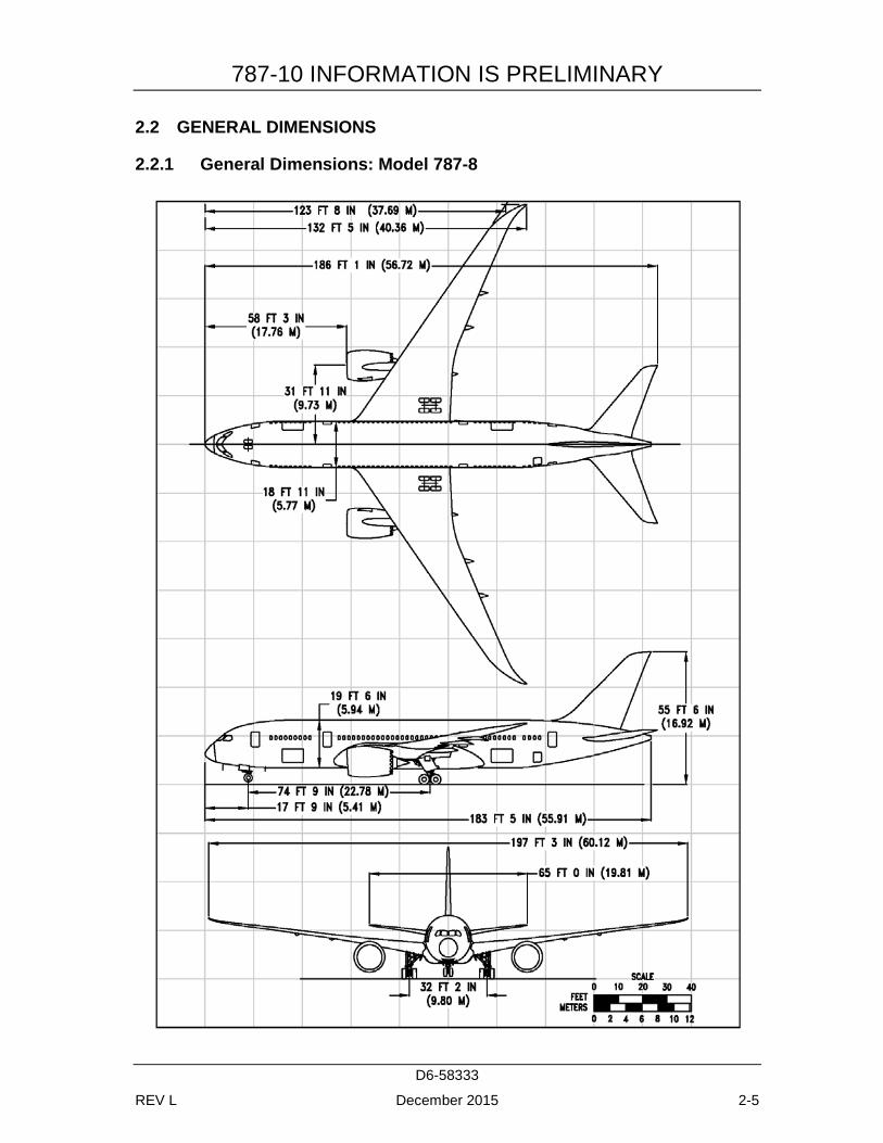
2.2 GENERAL DIMENSIONS
2.2.1 General Dimensions: Model 787-8
787-10 INFORMATION IS PRELIMINARY
D6-58333
REV L December 2015 2-6
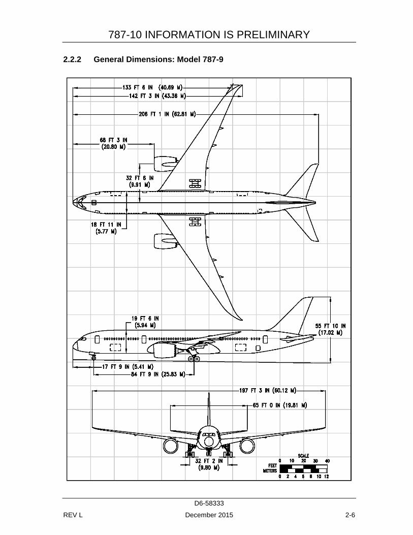
2.2.2 General Dimensions: Model 787-9
787-10 INFORMATION IS PRELIMINARY
D6-58333
REV L December 2015 2-7
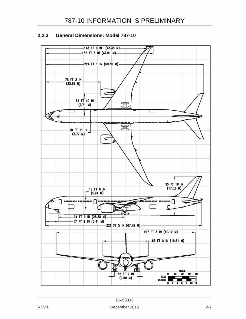
2.2.3 General Dimensions: Model 787-10
787-10 INFORMATION IS PRELIMINARY
D6-58333
REV L December 2015 2-8
2.3 GROUND CLEARANCES
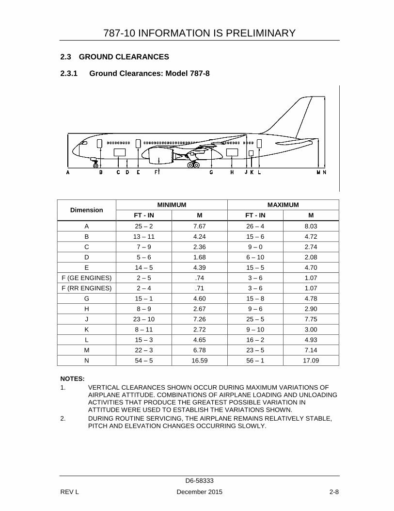
2.3.1 Ground Clearances: Model 787-8
Dimension MINIMUM MAXIMUM
FT - IN M FT - IN M A 25 – 2 7.67 26 – 4 8.03 B 13 – 11 4.24 15 – 6 4.72 C 7 – 9 2.36 9 – 0 2.74 D 5 – 6 1.68 6 – 10 2.08 E 14 – 5 4.39 15 – 5 4.70
F (GE ENGINES) 2 – 5 .74 3 – 6 1.07 F (RR ENGINES) 2 – 4 .71 3 – 6 1.07
G 15 – 1 4.60 15 – 8 4.78 H 8 – 9 2.67 9 – 6 2.90 J 23 – 10 7.26 25 – 5 7.75 K 8 – 11 2.72 9 – 10 3.00 L 15 – 3 4.65 16 – 2 4.93 M 22 – 3 6.78 23 – 5 7.14 N 54 – 5 16.59 56 – 1 17.09
NOTES: 1. VERTICAL CLEARANCES SHOWN OCCUR DURING MAXIMUM VARIATIONS OF
AIRPLANE ATTITUDE. COMBINATIONS OF AIRPLANE LOADING AND UNLOADING ACTIVITIES THAT PRODUCE THE GREATEST POSSIBLE VARIATION IN ATTITUDE WERE USED TO ESTABLISH THE VARIATIONS SHOWN.
2. DURING ROUTINE SERVICING, THE AIRPLANE REMAINS RELATIVELY STABLE, PITCH AND ELEVATION CHANGES OCCURRING SLOWLY.
787-10 INFORMATION IS PRELIMINARY
D6-58333
REV L December 2015 2-9
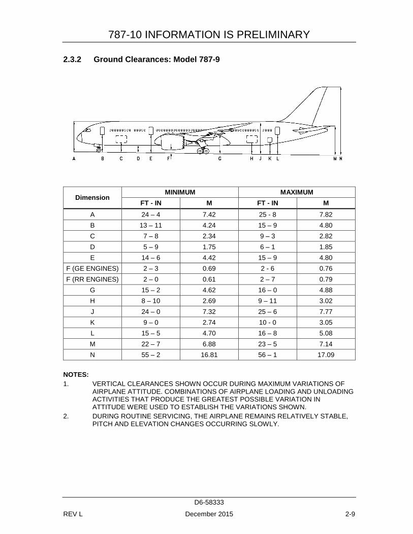
2.3.2 Ground Clearances: Model 787-9
Dimension MINIMUM MAXIMUM
FT - IN M FT - IN M A 24 – 4 7.42 25 - 8 7.82 B 13 – 11 4.24 15 – 9 4.80 C 7 – 8 2.34 9 – 3 2.82 D 5 – 9 1.75 6 – 1 1.85 E 14 – 6 4.42 15 – 9 4.80
F (GE ENGINES) 2 – 3 0.69 2 - 6 0.76 F (RR ENGINES) 2 – 0 0.61 2 – 7 0.79
G 15 – 2 4.62 16 – 0 4.88 H 8 – 10 2.69 9 – 11 3.02 J 24 – 0 7.32 25 – 6 7.77 K 9 – 0 2.74 10 - 0 3.05 L 15 – 5 4.70 16 – 8 5.08 M 22 – 7 6.88 23 – 5 7.14 N 55 – 2 16.81 56 – 1 17.09
NOTES: 1. VERTICAL CLEARANCES SHOWN OCCUR DURING MAXIMUM VARIATIONS OF
AIRPLANE ATTITUDE. COMBINATIONS OF AIRPLANE LOADING AND UNLOADING ACTIVITIES THAT PRODUCE THE GREATEST POSSIBLE VARIATION IN ATTITUDE WERE USED TO ESTABLISH THE VARIATIONS SHOWN.
2. DURING ROUTINE SERVICING, THE AIRPLANE REMAINS RELATIVELY STABLE, PITCH AND ELEVATION CHANGES OCCURRING SLOWLY.
787-10 INFORMATION IS PRELIMINARY
D6-58333
REV L December 2015 2-10
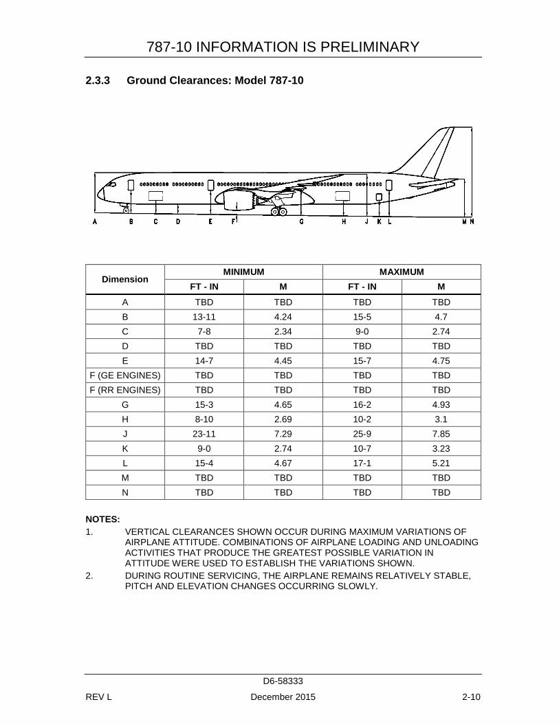
2.3.3 Ground Clearances: Model 787-10
Dimension MINIMUM MAXIMUM
FT - IN M FT - IN M A TBD TBD TBD TBD B 13-11 4.24 15-5 4.7 C 7-8 2.34 9-0 2.74 D TBD TBD TBD TBD E 14-7 4.45 15-7 4.75
F (GE ENGINES) TBD TBD TBD TBD F (RR ENGINES) TBD TBD TBD TBD
G 15-3 4.65 16-2 4.93 H 8-10 2.69 10-2 3.1 J 23-11 7.29 25-9 7.85 K 9-0 2.74 10-7 3.23 L 15-4 4.67 17-1 5.21 M TBD TBD TBD TBD N TBD TBD TBD TBD
NOTES: 1. VERTICAL CLEARANCES SHOWN OCCUR DURING MAXIMUM VARIATIONS OF
AIRPLANE ATTITUDE. COMBINATIONS OF AIRPLANE LOADING AND UNLOADING ACTIVITIES THAT PRODUCE THE GREATEST POSSIBLE VARIATION IN ATTITUDE WERE USED TO ESTABLISH THE VARIATIONS SHOWN.
2. DURING ROUTINE SERVICING, THE AIRPLANE REMAINS RELATIVELY STABLE, PITCH AND ELEVATION CHANGES OCCURRING SLOWLY.
787-10 INFORMATION IS PRELIMINARY
D6-58333
REV L December 2015 2-11
2.4 INTERIOR ARRANGEMENTS
2.4.1 Interior Arrangements - Typical: Model 787-8, 787-9, 787-10
787-10 INFORMATION IS PRELIMINARY
D6-58333
REV L December 2015 2-12
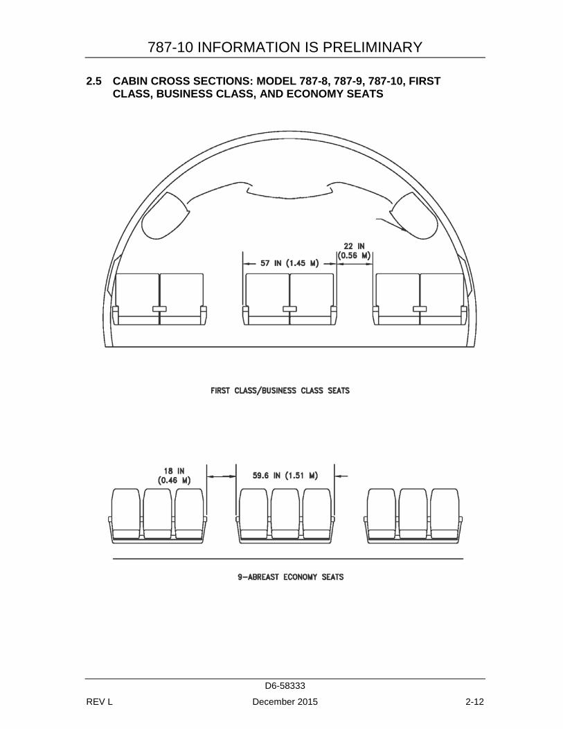
2.5 CABIN CROSS SECTIONS: MODEL 787-8, 787-9, 787-10, FIRST CLASS, BUSINESS CLASS, AND ECONOMY SEATS
787-10 INFORMATION IS PRELIMINARY
D6-58333
REV L December 2015 2-13
2.6 LOWER CARGO COMPARTMENTS
2.6.1 Lower Cargo Compartments: Model 787-8, Containers and Bulk Cargo
787-10 INFORMATION IS PRELIMINARY
D6-58333
REV L December 2015 2-14
2.6.2 Lower Cargo Compartments: Model 787-9, Containers and Bulk Cargo
787-10 INFORMATION IS PRELIMINARY
D6-58333
REV L December 2015 2-15
2.6.3 Lower Cargo Compartments: Model 787-10, Containers and Bulk Cargo
787-10 INFORMATION IS PRELIMINARY
D6-58333
REV L December 2015 2-16
2.7 DOOR CLEARANCES
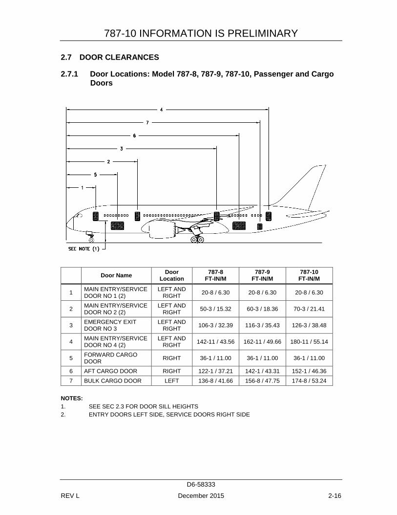
2.7.1 Door Locations: Model 787-8, 787-9, 787-10, Passenger and Cargo Doors
Door Name Door Location
787-8 FT-IN/M
787-9 FT-IN/M
787-10 FT-IN/M
1 MAIN ENTRY/SERVICE DOOR NO 1 (2)
LEFT AND RIGHT 20-8 / 6.30 20-8 / 6.30 20-8 / 6.30
2 MAIN ENTRY/SERVICE DOOR NO 2 (2)
LEFT AND RIGHT 50-3 / 15.32 60-3 / 18.36 70-3 / 21.41
3 EMERGENCY EXIT DOOR NO 3
LEFT AND RIGHT 106-3 / 32.39 116-3 / 35.43 126-3 / 38.48
4 MAIN ENTRY/SERVICE DOOR NO 4 (2)
LEFT AND RIGHT 142-11 / 43.56 162-11 / 49.66 180-11 / 55.14
5 FORWARD CARGO DOOR RIGHT 36-1 / 11.00 36-1 / 11.00 36-1 / 11.00
6 AFT CARGO DOOR RIGHT 122-1 / 37.21 142-1 / 43.31 152-1 / 46.36 7 BULK CARGO DOOR LEFT 136-8 / 41.66 156-8 / 47.75 174-8 / 53.24
NOTES: 1. SEE SEC 2.3 FOR DOOR SILL HEIGHTS 2. ENTRY DOORS LEFT SIDE, SERVICE DOORS RIGHT SIDE
787-10 INFORMATION IS PRELIMINARY
D6-58333
REV L December 2015 2-17
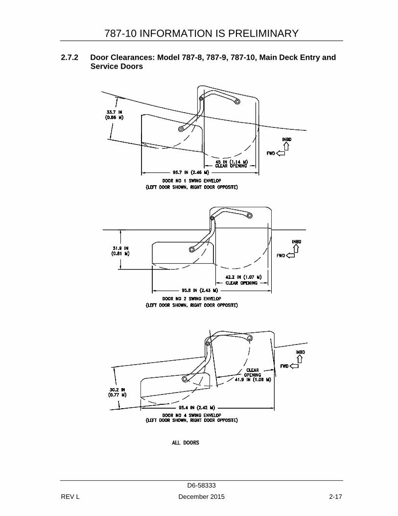
2.7.2 Door Clearances: Model 787-8, 787-9, 787-10, Main Deck Entry and Service Doors
787-10 INFORMATION IS PRELIMINARY
D6-58333
REV L December 2015 2-18
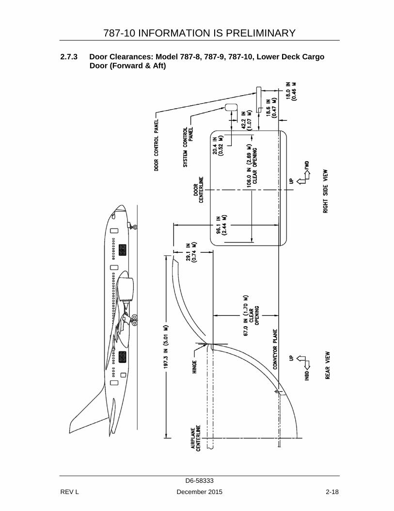
2.7.3 Door Clearances: Model 787-8, 787-9, 787-10, Lower Deck Cargo Door (Forward & Aft)
787-10 INFORMATION IS PRELIMINARY
D6-58333
REV L December 2015 2-19
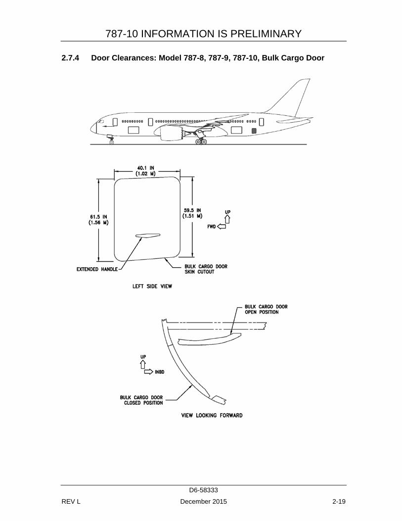
2.7.4 Door Clearances: Model 787-8, 787-9, 787-10, Bulk Cargo Door
787-10 INFORMATION IS PRELIMINARY
D6-58333
REV L December 2015 3-1
3.0 AIRPLANE PERFORMANCE
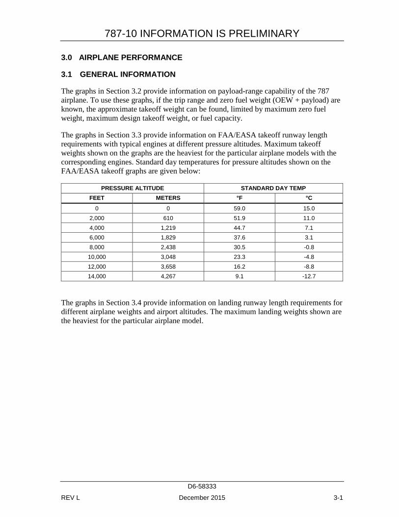
3.1 GENERAL INFORMATION
The graphs in Section 3.2 provide information on payload-range capability of the 787 airplane. To use these graphs, if the trip range and zero fuel weight (OEW + payload) are known, the approximate takeoff weight can be found, limited by maximum zero fuel weight, maximum design takeoff weight, or fuel capacity.
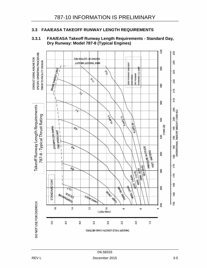
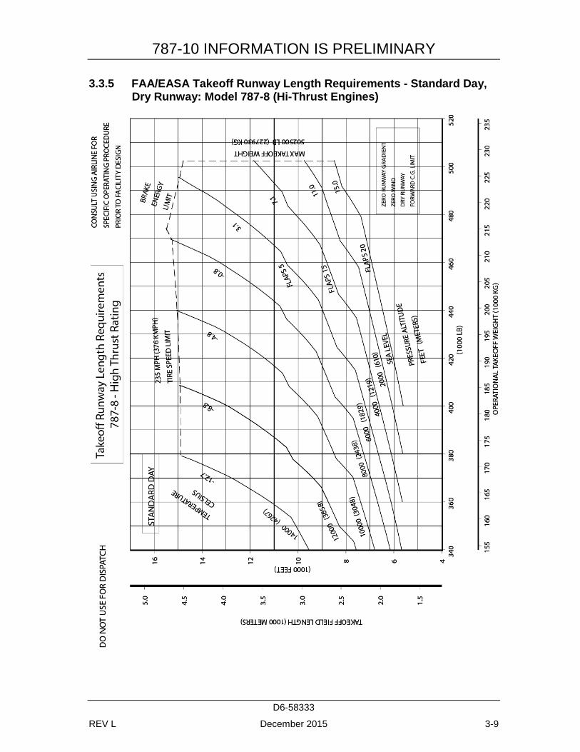
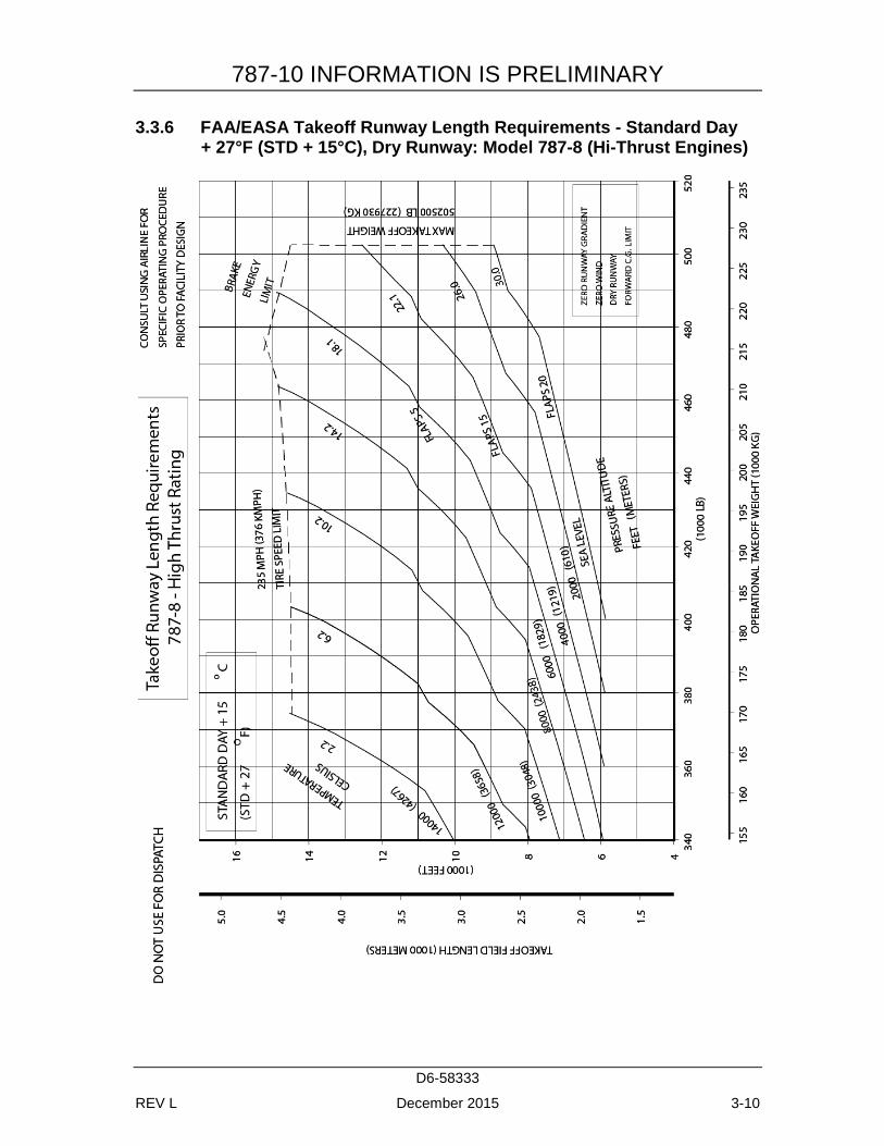
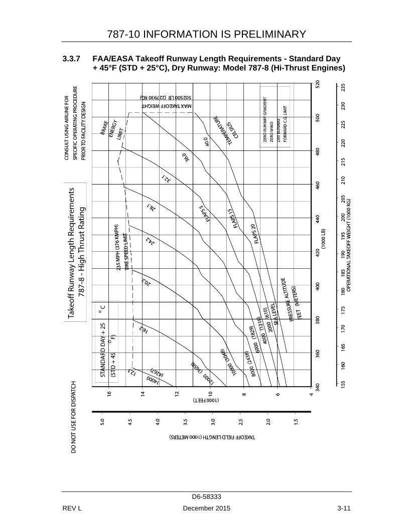
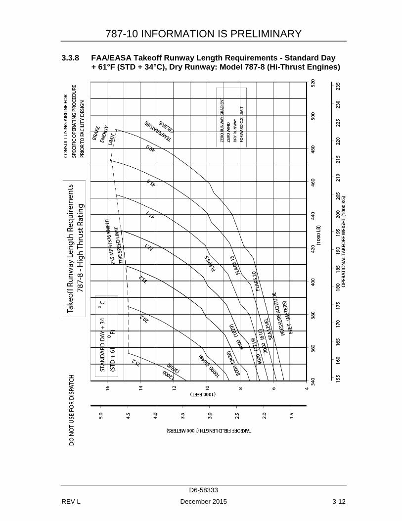
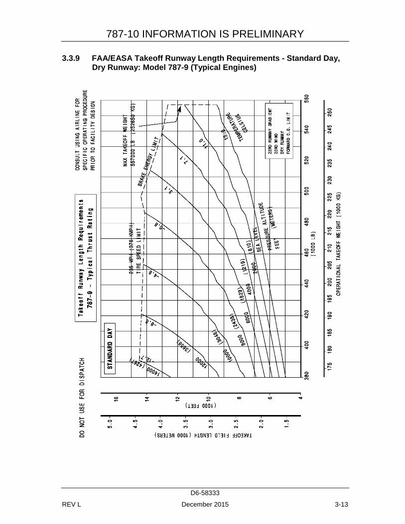
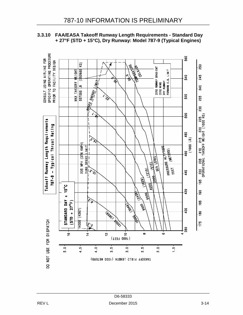
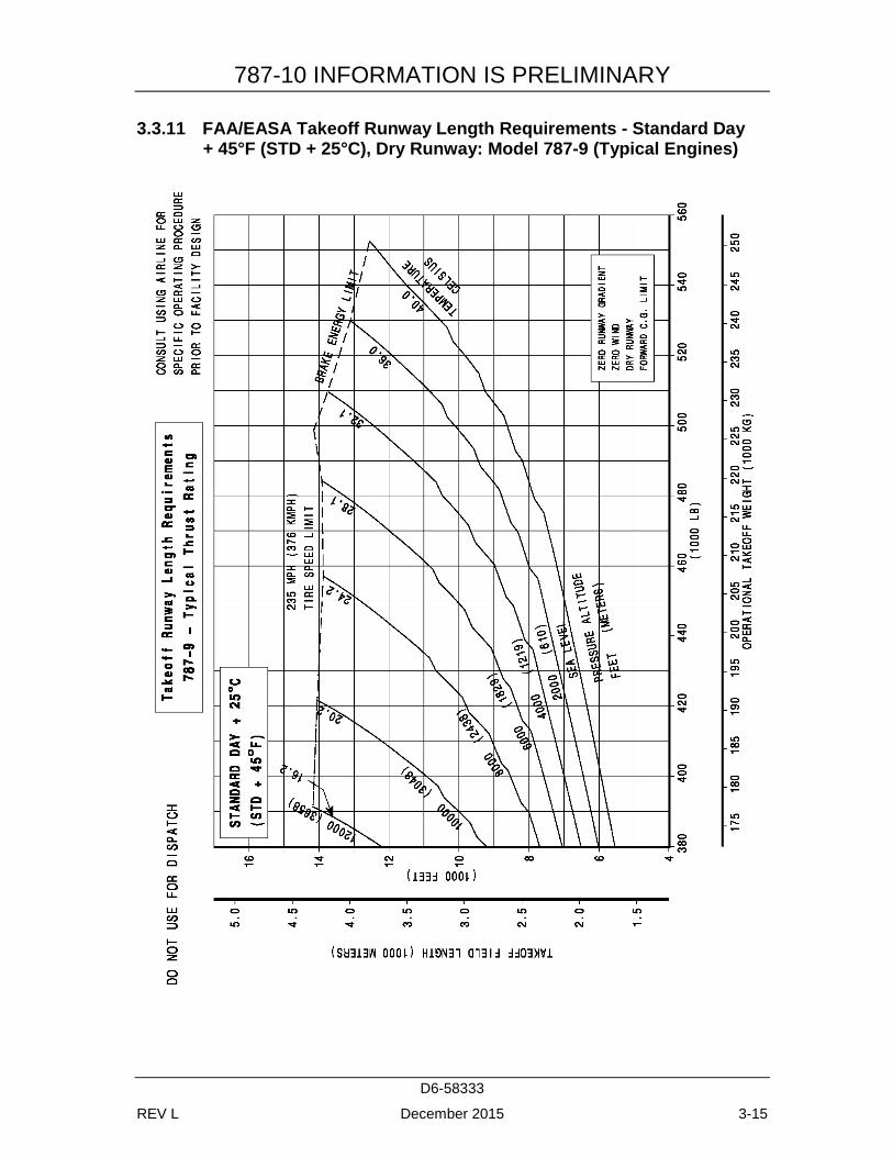
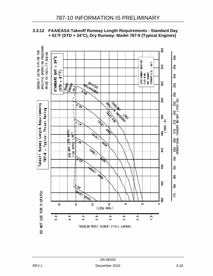
The graphs in Section 3.3 provide information on FAA/EASA takeoff runway length requirements with typical engines at different pressure altitudes. Maximum takeoff weights shown on the graphs are the heaviest for the particular airplane models with the corresponding engines. Standard day temperatures for pressure altitudes shown on the FAA/EASA takeoff graphs are given below:
PRESSURE ALTITUDE STANDARD DAY TEMP FEET METERS °F °C
0 0 59.0 15.0 2,000 610 51.9 11.0 4,000 1,219 44.7 7.1 6,000 1,829 37.6 3.1 8,000 2,438 30.5 -0.8
10,000 3,048 23.3 -4.8 12,000 3,658 16.2 -8.8 14,000 4,267 9.1 -12.7
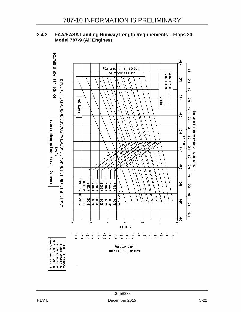
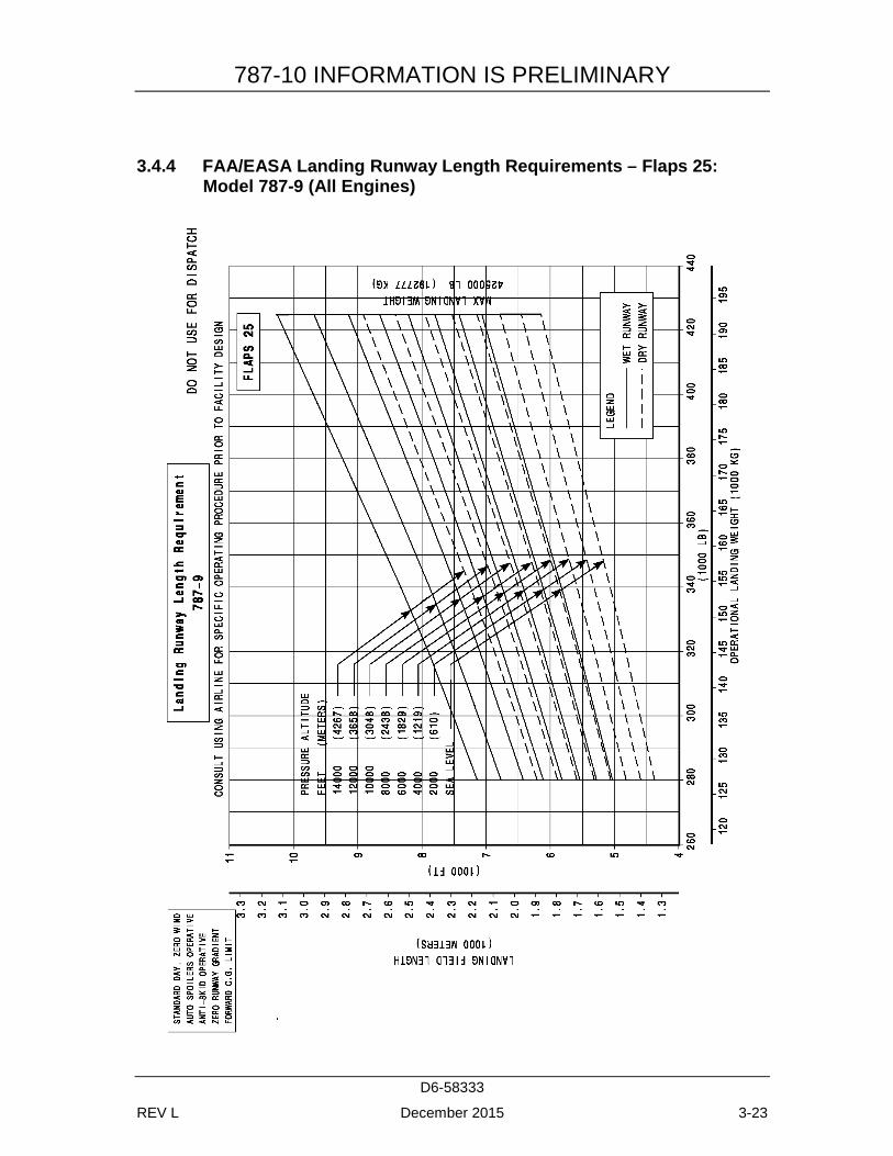
The graphs in Section 3.4 provide information on landing runway length requirements for different airplane weights and airport altitudes. The maximum landing weights shown are the heaviest for the particular airplane model.
787-10 INFORMATION IS PRELIMINARY
D6-58333
REV L December 2015 3-2
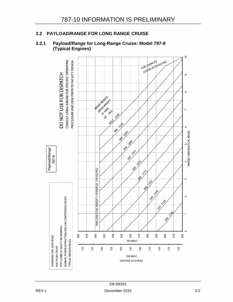
3.2 PAYLOAD/RANGE FOR LONG RANGE CRUISE
3.2.1 Payload/Range for Long-Range Cruise: Model 787-8 (Typical Engines)
787-10 INFORMATION IS PRELIMINARY
D6-58333
REV L December 2015 3-3
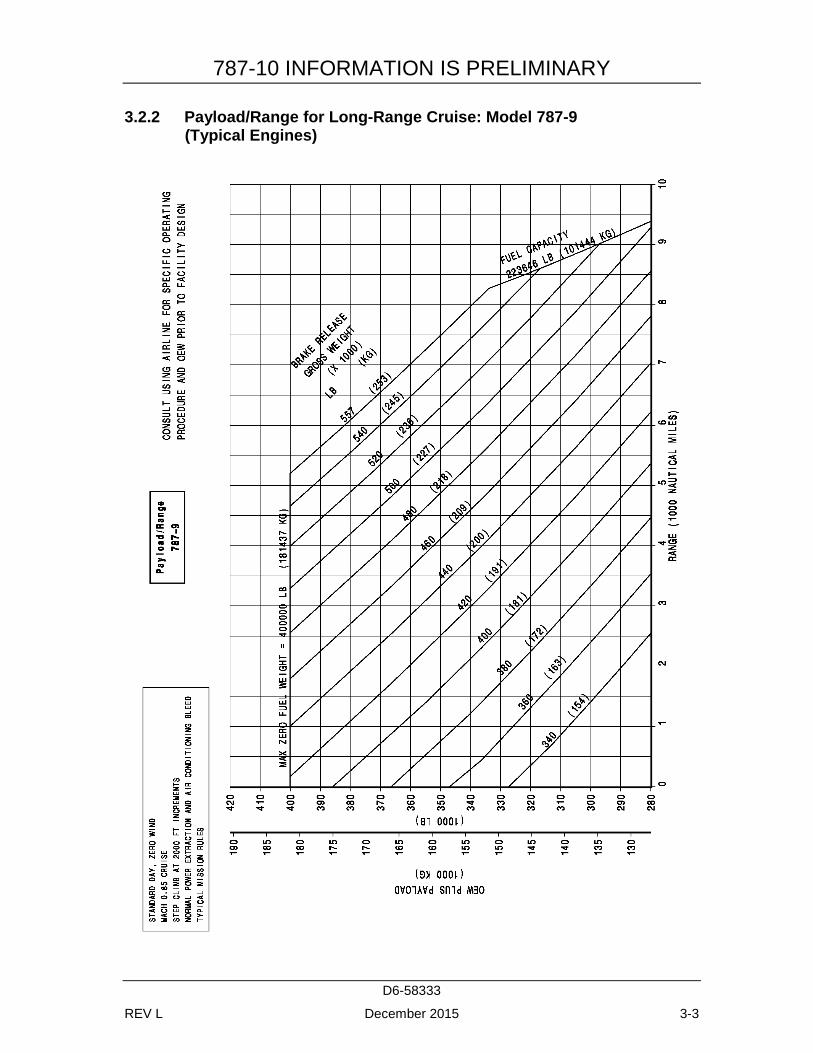
3.2.2 Payload/Range for Long-Range Cruise: Model 787-9 (Typical Engines)
787-10 INFORMATION IS PRELIMINARY
D6-58333
REV L December 2015 3-4
3.2.3 Payload/Range for Long-Range Cruise: Model 787-10 (Typical Engines)
DATA TO BE PROVIDED AT A LATER DATE
787-10 INFORMATION IS PRELIMINARY
D6-58333
REV L December 2015 3-5
3.3 FAA/EASA TAKEOFF RUNWAY LENGTH REQUIREMENTS
3.3.1 FAA/EASA Takeoff Runway Length Requirements - Standard Day, Dry Runway: Model 787-8 (Typical Engines)

787-10 INFORMATION IS PRELIMINARY
D6-58333
REV L December 2015 3-6
3.3.2 FAA/EASA TakeOff Runway Length Requirements - Standard Day + 27°F (STD + 15°C), Dry Runway: Model 787-8 (Typical Engines)
787-10 INFORMATION IS PRELIMINARY
D6-58333
REV L December 2015 3-7
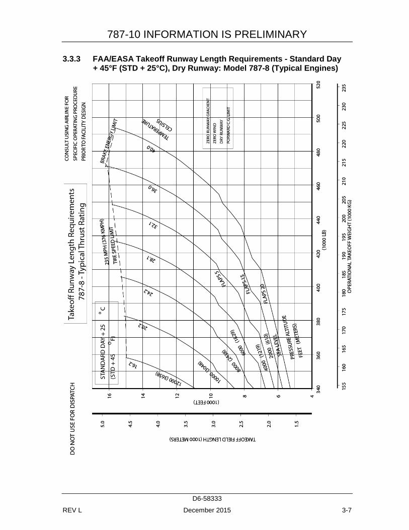
3.3.3 FAA/EASA Takeoff Runway Length Requirements - Standard Day + 45°F (STD + 25°C), Dry Runway: Model 787-8 (Typical Engines)
787-10 INFORMATION IS PRELIMINARY
D6-58333
REV L December 2015 3-8
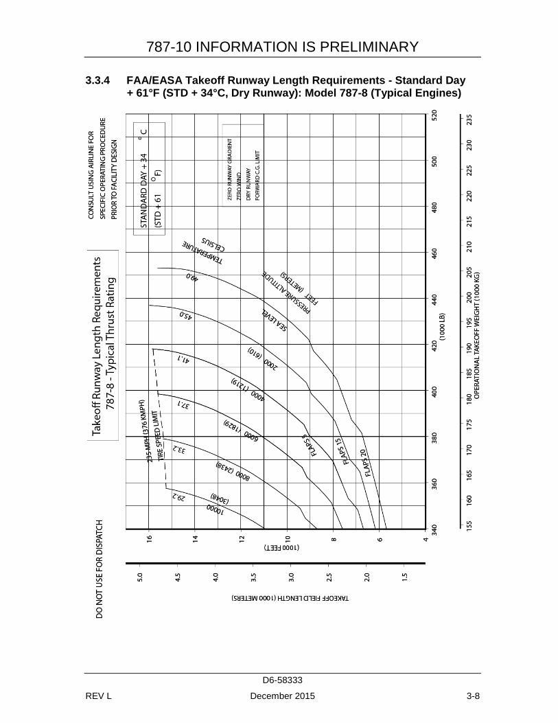
3.3.4 FAA/EASA Takeoff Runway Length Requirements - Standard Day + 61°F (STD + 34°C, Dry Runway): Model 787-8 (Typical Engines)
787-10 INFORMATION IS PRELIMINARY
D6-58333
REV L December 2015 3-9
3.3.5 FAA/EASA Takeoff Runway Length Requirements - Standard Day, Dry Runway: Model 787-8 (Hi-Thrust Engines)
787-10 INFORMATION IS PRELIMINARY
D6-58333
REV L December 2015 3-10
3.3.6 FAA/EASA Takeoff Runway Length Requirements - Standard Day + 27°F (STD + 15°C), Dry Runway: Model 787-8 (Hi-Thrust Engines)
787-10 INFORMATION IS PRELIMINARY
D6-58333
REV L December 2015 3-11
3.3.7 FAA/EASA Takeoff Runway Length Requirements - Standard Day + 45°F (STD + 25°C), Dry Runway: Model 787-8 (Hi-Thrust Engines)
787-10 INFORMATION IS PRELIMINARY
D6-58333
REV L December 2015 3-12
3.3.8 FAA/EASA Takeoff Runway Length Requirements - Standard Day + 61°F (STD + 34°C), Dry Runway: Model 787-8 (Hi-Thrust Engines)
787-10 INFORMATION IS PRELIMINARY
D6-58333
REV L December 2015 3-13
3.3.9 FAA/EASA Takeoff Runway Length Requirements - Standard Day, Dry Runway: Model 787-9 (Typical Engines)
787-10 INFORMATION IS PRELIMINARY
D6-58333
REV L December 2015 3-14
3.3.10 FAA/EASA Takeoff Runway Length Requirements - Standard Day + 27°F (STD + 15°C), Dry Runway: Model 787-9 (Typical Engines)
787-10 INFORMATION IS PRELIMINARY
D6-58333
REV L December 2015 3-15
3.3.11 FAA/EASA Takeoff Runway Length Requirements - Standard Day + 45°F (STD + 25°C), Dry Runway: Model 787-9 (Typical Engines)
787-10 INFORMATION IS PRELIMINARY
D6-58333
REV L December 2015 3-16
3.3.12 FAA/EASA Takeoff Runway Length Requirements - Standard Day + 61°F (STD + 34°C), Dry Runway: Model 787-9 (Typical Engines)
787-10 INFORMATION IS PRELIMINARY
D6-58333
REV L December 2015 3-17
3.3.13 FAA/EASA Takeoff Runway Length Requirements: Model 787-9, (Hi-Thrust Engines)
DATA TO BE PROVIDED AT A LATER DATE
787-10 INFORMATION IS PRELIMINARY
D6-58333
REV L December 2015 3-18
3.3.14 FAA/EASA Takeoff Runway Length Requirements: Model 787-10
DATA TO BE PROVIDED AT A LATER DATE
787-10 INFORMATION IS PRELIMINARY
D6-58333
REV L December 2015 3-19
3.4 FAA/EASA LANDING RUNWAY LENGTH REQUIREMENTS
3.4.1 FAA/EASA Landing Runway Length Requirements – Flaps 30: Model 787-8 (All Engines)
787-10 INFORMATION IS PRELIMINARY
D6-58333
REV L December 2015 3-20
3.4.2 FAA/EASA Landing Runway Length Requirements – Flaps 25: Model 787-8 (All Engines)

787-10 INFORMATION IS PRELIMINARY
D6-58333
REV L December 2015 3-21
787-10 INFORMATION IS PRELIMINARY
D6-58333
REV L December 2015 3-22
3.4.3 FAA/EASA Landing Runway Length Requirements – Flaps 30: Model 787-9 (All Engines)
787-10 INFORMATION IS PRELIMINARY
D6-58333
REV L December 2015 3-23
3.4.4 FAA/EASA Landing Runway Length Requirements – Flaps 25: Model 787-9 (All Engines)
787-10 INFORMATION IS PRELIMINARY
D6-58333
REV L December 2015 3-24
3.4.5 FAA/EASA Landing Runway Length Requirements: Model 787-10 (All Engines)
DATA TO BE PROVIDED AT A LATER DATE
787-10 INFORMATION IS PRELIMINARY
D6-58333
REV L December 2015 4-25
4.0 GROUND MANEUVERING
4.1 GENERAL INFORMATION
This section provides airplane turning capability and maneuvering characteristics.
For ease of presentation, these data have been determined from the theoretical limits imposed by the geometry of the aircraft, and where noted, provide for a normal allowance for tire slippage. As such, they reflect the turning capability of the aircraft in favorable operating circumstances. These data should be used only as guidelines for the method of determination of such parameters and for the maneuvering characteristics of this aircraft.
In the ground operating mode, varying airline practices may demand that more conservative turning procedures be adopted to avoid excessive tire wear and reduce possible maintenance problems. Airline operating procedures will vary in the level of performance over a wide range of operating circumstances throughout the world. Variations from standard aircraft operating patterns may be necessary to satisfy physical constraints within the maneuvering area, such as adverse grades, limited area, or high risk of jet blast damage. For these reasons, ground maneuvering requirements should be coordinated with the using airlines prior to layout planning.
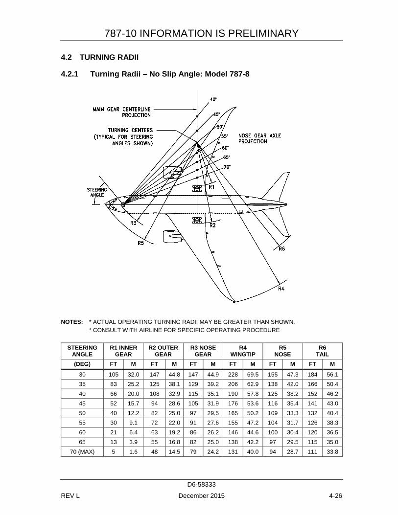
Section 4.2 presents turning radii for various nose gear steering angles. Radii for the main and nose gears are measured from the turn center to the outside of the tire.
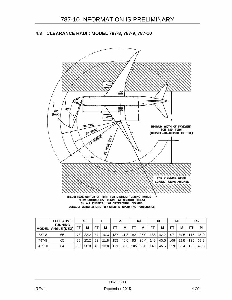
Section 4.3 shows data on minimum width of pavement required for 180° turn.
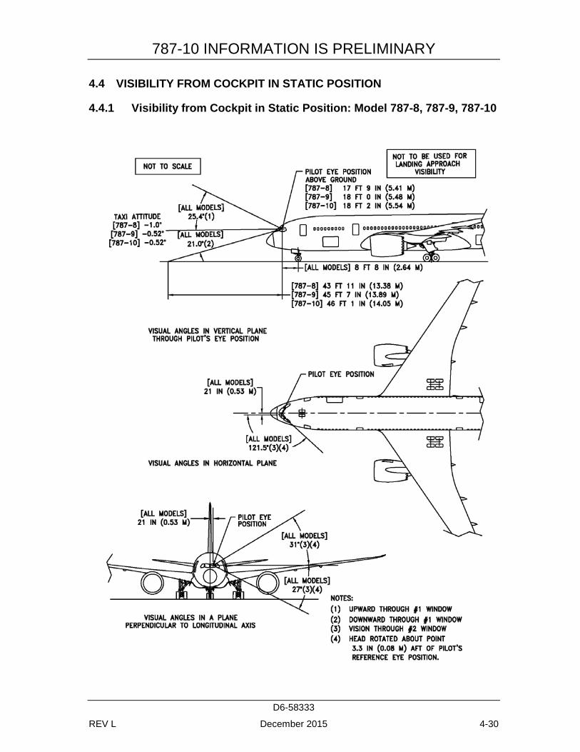
Section 4.4 provides pilot visibility data from the cockpit and the limits of ambinocular vision through the windows. Ambinocular vision is defined as the total field of vision seen simultaneously by both eyes.
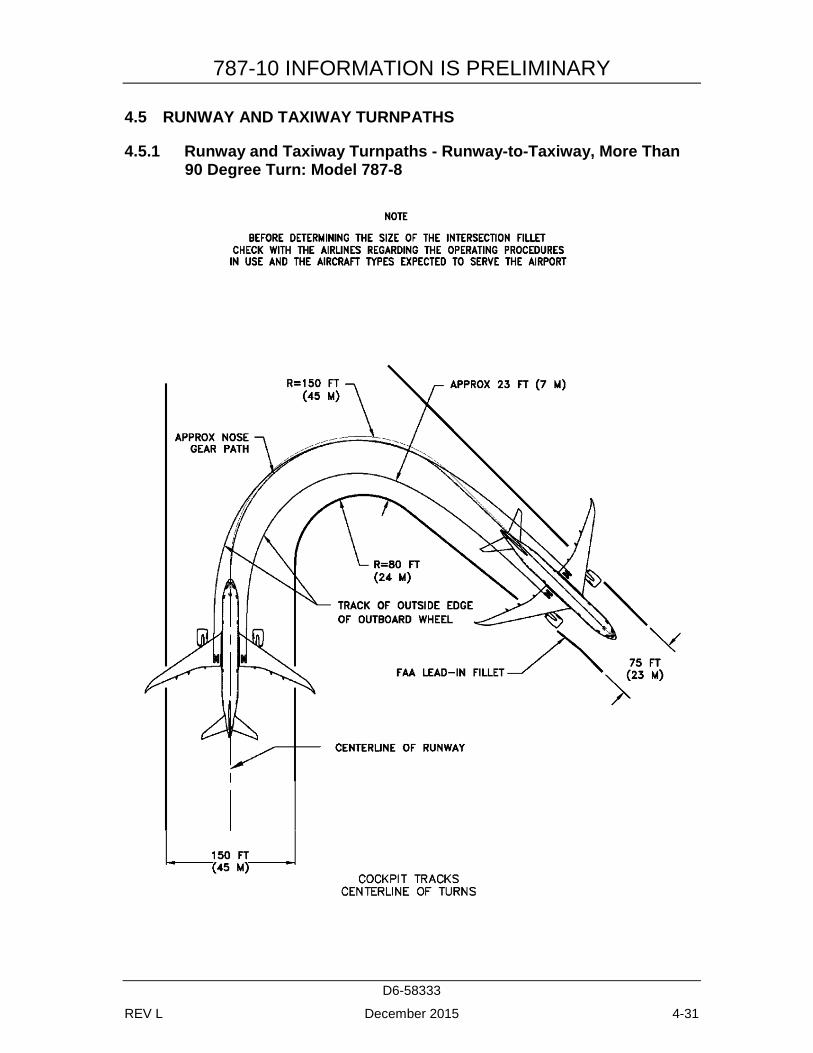
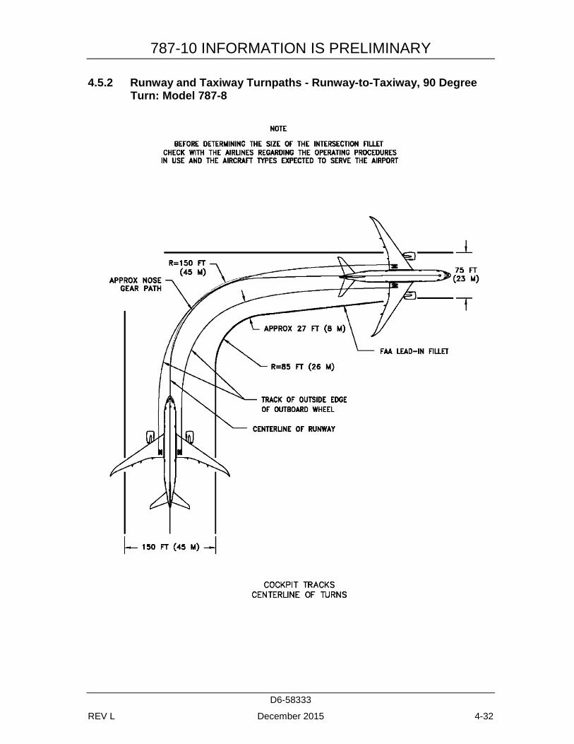
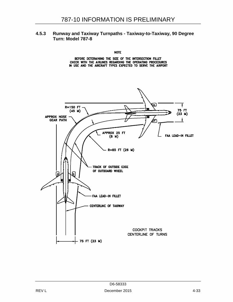
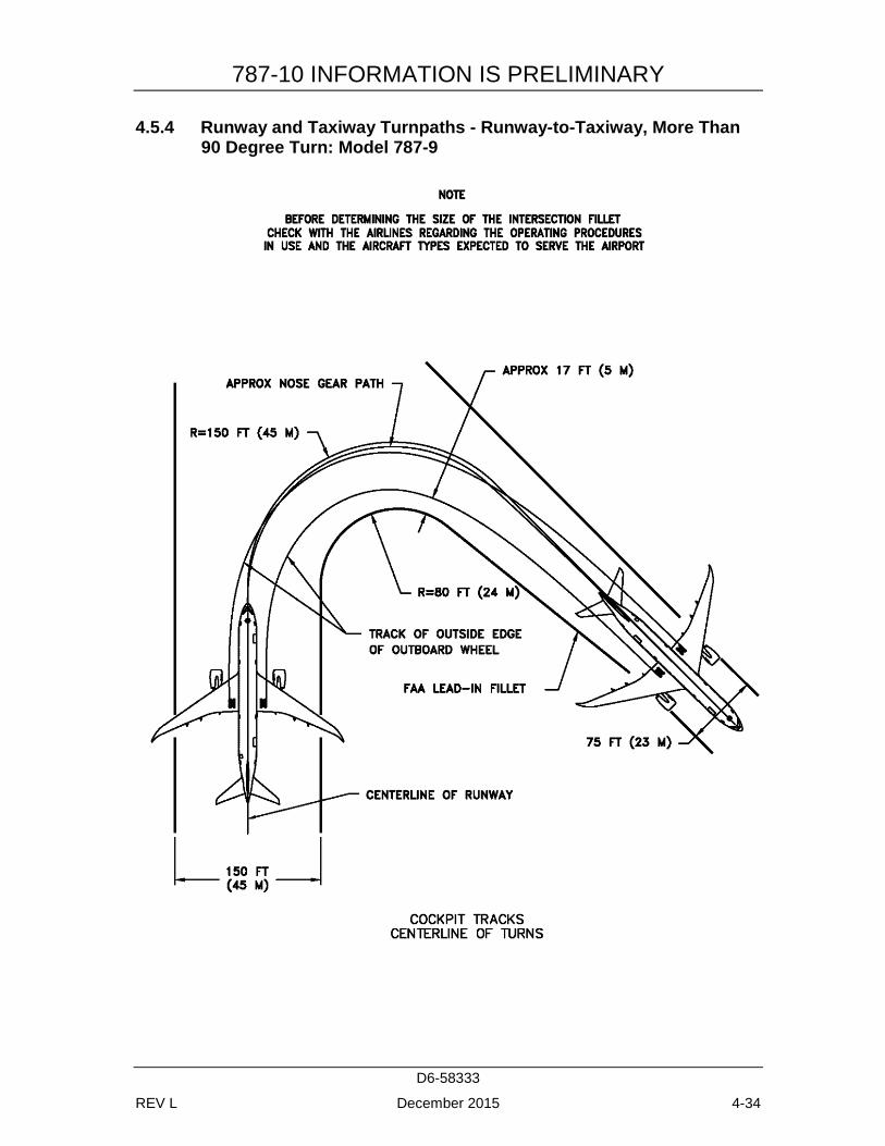
Section 4.5 shows approximate wheel paths for various runway and taxiway turn scenarios. The pavement fillet geometries are based on the FAA’s Advisory Circular (AC) 150/5300-13 (thru change 16). They represent typical fillet geometries built at many airports worldwide. ICAO and other civil aviation authorities publish many different fillet design methods. Prior to determining the size of fillets, airports are advised to check with the airlines regarding the operating procedures and aircraft types they expect to use at the airport. Further, given the cost of modifying fillets and the operational impact to ground movement and air traffic during construction, airports may want to design critical fillets for larger aircraft types to minimize future operational impacts. Section 4.6 illustrates a typical runway holding bay configuration.
787-10 INFORMATION IS PRELIMINARY
D6-58333
REV L December 2015 4-26
4.2 TURNING RADII
4.2.1 Turning Radii – No Slip Angle: Model 787-8
NOTES: * ACTUAL OPERATING TURNING RADII MAY BE GREATER THAN SHOWN. * CONSULT WITH AIRLINE FOR SPECIFIC OPERATING PROCEDURE
STEERING
ANGLE R1 INNER
GEAR R2 OUTER
GEAR R3 NOSE
GEAR R4
WINGTIP R5
NOSE R6
TAIL (DEG) FT M FT M FT M FT M FT M FT M
30 105 32.0 147 44.8 147 44.9 228 69.5 155 47.3 184 56.1 35 83 25.2 125 38.1 129 39.2 206 62.9 138 42.0 166 50.4 40 66 20.0 108 32.9 115 35.1 190 57.8 125 38.2 152 46.2 45 52 15.7 94 28.6 105 31.9 176 53.6 116 35.4 141 43.0 50 40 12.2 82 25.0 97 29.5 165 50.2 109 33.3 132 40.4 55 30 9.1 72 22.0 91 27.6 155 47.2 104 31.7 126 38.3 60 21 6.4 63 19.2 86 26.2 146 44.6 100 30.4 120 36.5 65 13 3.9 55 16.8 82 25.0 138 42.2 97 29.5 115 35.0
70 (MAX) 5 1.6 48 14.5 79 24.2 131 40.0 94 28.7 111 33.8
787-10 INFORMATION IS PRELIMINARY
D6-58333
REV L December 2015 4-27
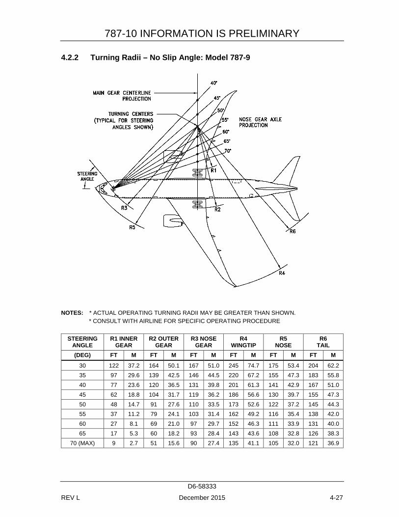
4.2.2 Turning Radii – No Slip Angle: Model 787-9
NOTES: * ACTUAL OPERATING TURNING RADII MAY BE GREATER THAN SHOWN. * CONSULT WITH AIRLINE FOR SPECIFIC OPERATING PROCEDURE
STEERING
ANGLE R1 INNER
GEAR R2 OUTER
GEAR R3 NOSE
GEAR R4
WINGTIP R5
NOSE R6
TAIL (DEG) FT M FT M FT M FT M FT M FT M
30 122 37.2 164 50.1 167 51.0 245 74.7 175 53.4 204 62.2 35 97 29.6 139 42.5 146 44.5 220 67.2 155 47.3 183 55.8 40 77 23.6 120 36.5 131 39.8 201 61.3 141 42.9 167 51.0 45 62 18.8 104 31.7 119 36.2 186 56.6 130 39.7 155 47.3 50 48 14.7 91 27.6 110 33.5 173 52.6 122 37.2 145 44.3 55 37 11.2 79 24.1 103 31.4 162 49.2 116 35.4 138 42.0 60 27 8.1 69 21.0 97 29.7 152 46.3 111 33.9 131 40.0 65 17 5.3 60 18.2 93 28.4 143 43.6 108 32.8 126 38.3
70 (MAX) 9 2.7 51 15.6 90 27.4 135 41.1 105 32.0 121 36.9

787-10 INFORMATION IS PRELIMINARY
D6-58333
REV L December 2015 4-28
4.2.3 Turning Radii – No Slip Angle: Model 787-10
NOTES: * ACTUAL OPERATING TURNING RADII MAY BE GREATER THAN SHOWN. * CONSULT WITH AIRLINE FOR SPECIFIC OPERATING PROCEDURE
STEERING
ANGLE R1 INNER
GEAR R2 OUTER
GEAR R3 NOSE
GEAR R4
WINGTIP R5
NOSE R6
TAIL (DEG) FT M FT M FT M FT M FT M FT M
30 140 42.5 182 55.4 187 57.1 262 80.0 195 59.4 223 68.0 35 111 33.9 154 46.8 164 49.9 235 71.5 172 52.6 199 60.7 40 89 27.3 132 40.1 146 44.6 213 64.9 156 47.6 182 55.3 45 72 21.8 114 34.7 133 40.6 195 59.6 144 44.0 168 51.2 50 57 17.3 99 30.2 123 37.5 181 55.1 135 41.2 157 47.9 55 44 13.4 86 26.2 115 35.1 168 51.3 128 39.1 148 45.2 60 32 9.9 75 22.8 109 33.2 157 48.0 123 37.4 141 43.0 65 22 6.7 64 19.6 104 31.8 147 44.9 119 36.2 135 41.1
70 (MAX) 13 3.9 55 16.7 101 30.7 138 42.1 116 35.2 130 39.6
787-10 INFORMATION IS PRELIMINARY
D6-58333
REV L December 2015 4-29
4.3 CLEARANCE RADII: MODEL 787-8, 787-9, 787-10
MODEL
EFFECTIVE TURNING
ANGLE (DEG)
X Y A R3 R4 R5 R6
FT M FT M FT M FT M FT M FT M FT M
787-8 65 73 22.2 34 10.3 137 41.8 82 25.0 138 42.2 97 29.5 115 35.0 787-9 65 83 25.2 39 11.8 153 46.6 93 28.4 143 43.6 108 32.8 126 38.3
787-10 64 93 28.3 45 13.8 171 52.3 105 32.0 149 45.5 119 36.4 136 41.5
787-10 INFORMATION IS PRELIMINARY
D6-58333
REV L December 2015 4-30
4.4 VISIBILITY FROM COCKPIT IN STATIC POSITION
4.4.1 Visibility from Cockpit in Static Position: Model 787-8, 787-9, 787-10
787-10 INFORMATION IS PRELIMINARY
D6-58333
REV L December 2015 4-31
4.5 RUNWAY AND TAXIWAY TURNPATHS
4.5.1 Runway and Taxiway Turnpaths - Runway-to-Taxiway, More Than 90 Degree Turn: Model 787-8
787-10 INFORMATION IS PRELIMINARY
D6-58333
REV L December 2015 4-32
4.5.2 Runway and Taxiway Turnpaths - Runway-to-Taxiway, 90 Degree Turn: Model 787-8
787-10 INFORMATION IS PRELIMINARY
D6-58333
REV L December 2015 4-33
4.5.3 Runway and Taxiway Turnpaths - Taxiway-to-Taxiway, 90 Degree Turn: Model 787-8
787-10 INFORMATION IS PRELIMINARY
D6-58333
REV L December 2015 4-34
4.5.4 Runway and Taxiway Turnpaths - Runway-to-Taxiway, More Than 90 Degree Turn: Model 787-9
787-10 INFORMATION IS PRELIMINARY
D6-58333
REV L December 2015 4-35
4.5.5 Runway and Taxiway Turnpaths - Runway-to-Taxiway, 90 Degree Turn: Model 787-9
787-10 INFORMATION IS PRELIMINARY
D6-58333
REV L December 2015 4-36
4.5.6 Runway and Taxiway Turnpaths - Taxiway-to-Taxiway, 90 Degree Turn: Model 787-9
787-10 INFORMATION IS PRELIMINARY
D6-58333
REV L December 2015 4-37
4.5.7 Runway and Taxiway Turnpaths - Runway-to-Taxiway, More Than 90 Degree Turn: Model 787-10
787-10 INFORMATION IS PRELIMINARY
D6-58333
REV L December 2015 4-38
4.5.8 Runway and Taxiway Turnpaths - Runway-to-Taxiway, 90 Degree Turn: Model 787-10
787-10 INFORMATION IS PRELIMINARY
D6-58333
REV L December 2015 4-39
4.5.9 Runway and Taxiway Turnpaths - Taxiway-to-Taxiway, 90 Degree Turn: Model 787-10
787-10 INFORMATION IS PRELIMINARY
D6-58333
REV L December 2015 4-40
4.6 RUNWAY HOLDING BAY: MODEL 787-8, 787-9, 787-10

787-10 INFORMATION IS PRELIMINARY
D6-58333
REV L December 2015 4-41
787-10 INFORMATION IS PRELIMINARY
D6-58333
REV L December 2015 5-1
5.0 TERMINAL SERVICING
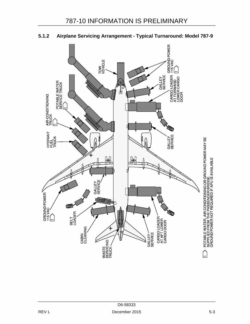
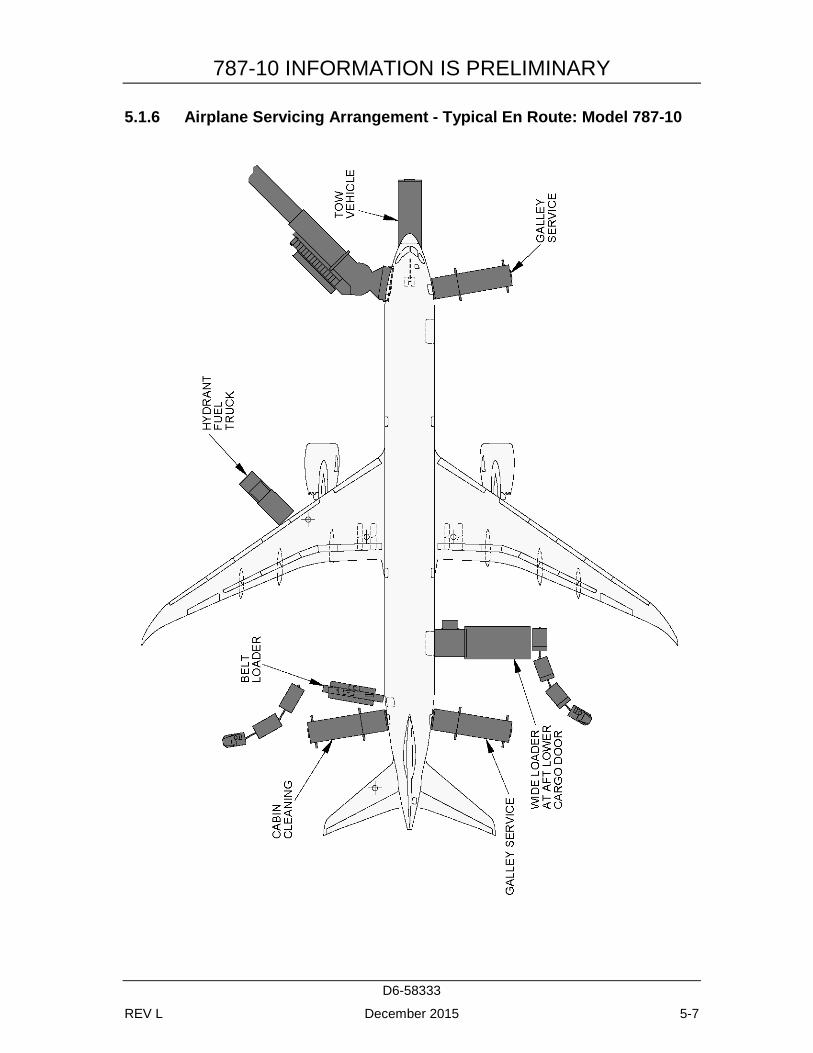
During turnaround at the terminal, certain services must be performed on the aircraft, usually within a given time, to meet flight schedules. This section shows service vehicle arrangements, schedules, locations of service points, and typical service requirements. The data presented in this section reflect ideal conditions for a single airplane. Service requirements may vary according to airplane condition and airline procedure.
Section 5.1 shows typical arrangements of ground support equipment during turnaround. As noted, if the auxiliary power unit (APU) is used, the electrical, air start, and air-conditioning service vehicles would not be required. Passenger loading bridges or portable passenger stairs could be used to load or unload passengers.
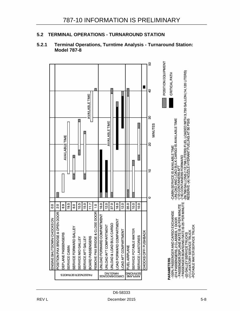
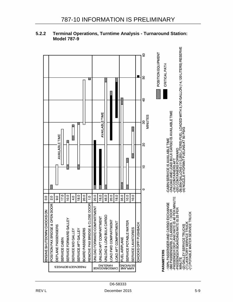
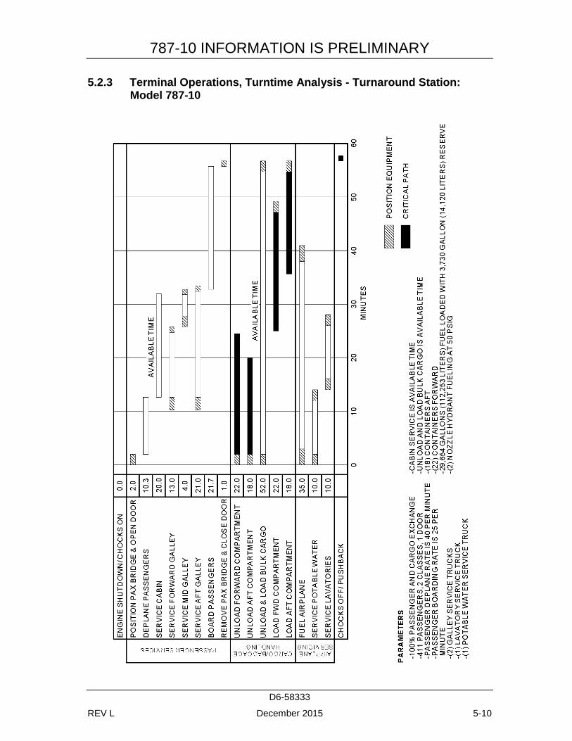
Sections 5.2 and 5.3 show typical service times at the terminal. These charts give typical schedules for performing service on the airplane within a given time. Service times may be rearranged to suit availability of personnel, airplane configuration, and degree of service required.
Section 5.4 shows the locations of ground service connections in graphic and in tabular forms. Typical capacities and service requirements are shown in the tables. Services with requirements that vary with conditions are described in subsequent sections.
Section 5.5 shows minimum electrical ground power requirements for engine start. The curves are based on 120-second and 180-second start times depending on the ground power unit.
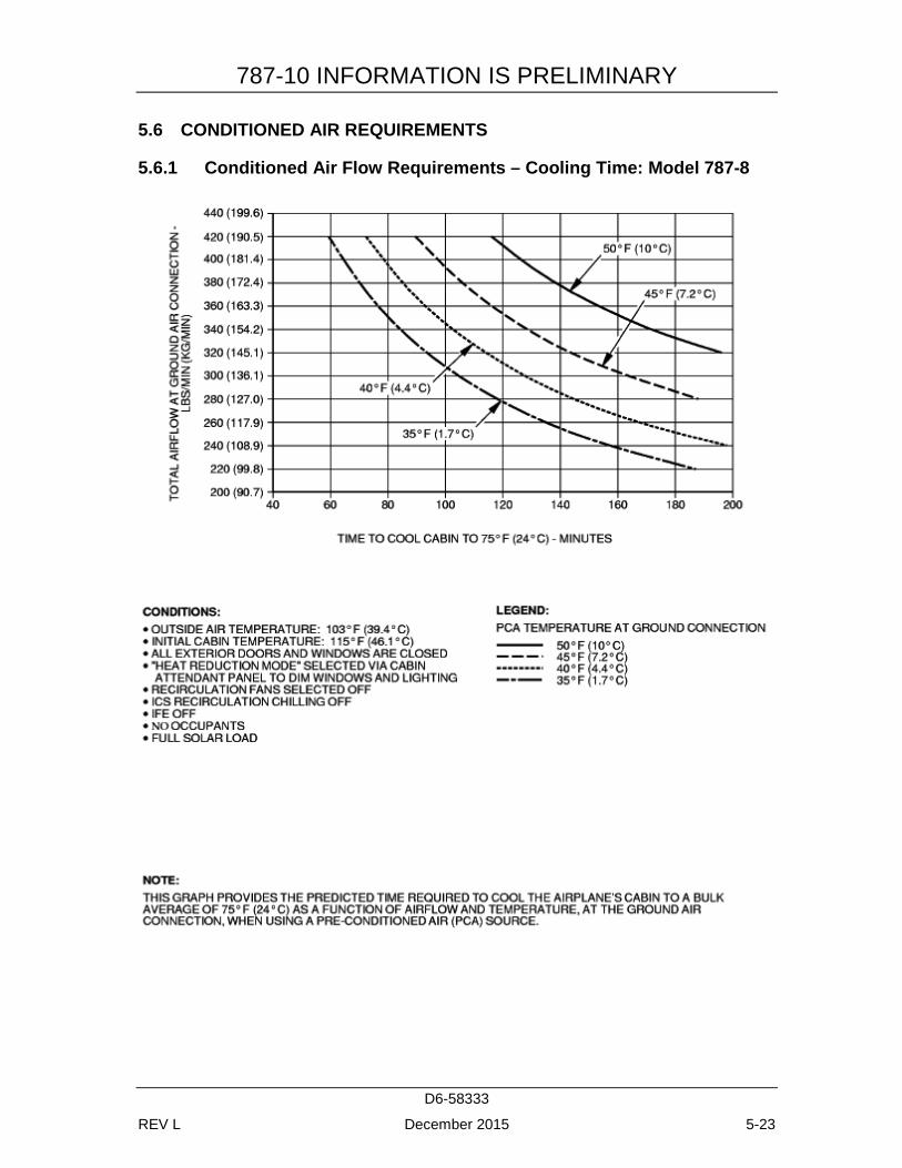
Section 5.6 shows air conditioning requirements for heating and cooling (pull-down and pull-up) using ground conditioned air. The curves show airflow requirements to heat or cool the airplane within a given time at ambient conditions.
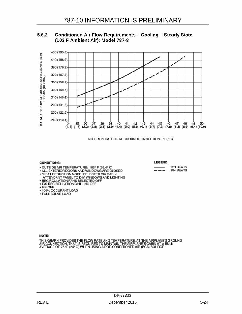
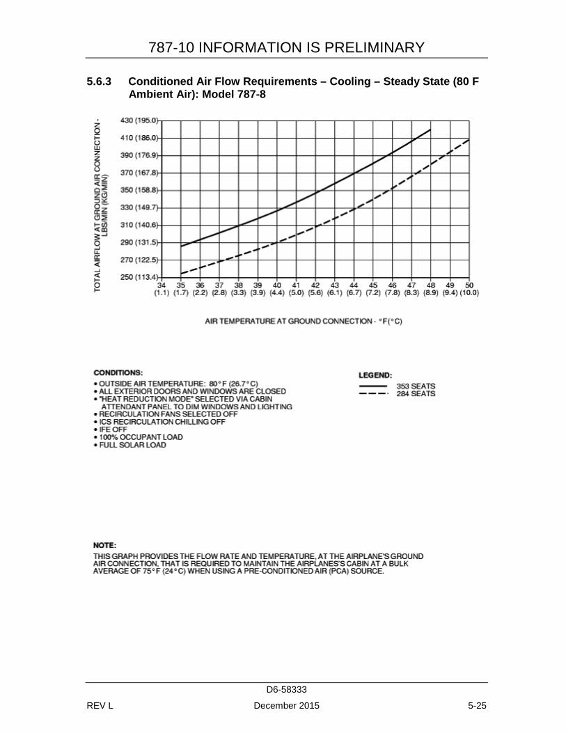
Section 5.7 shows air conditioning requirements for heating and cooling to maintain a constant cabin air temperature using low pressure conditioned air. This conditioned air is supplied through an 8-in (20.3 cm) ground air connection (GAC) directly to the passenger cabin, bypassing the air cycle machines.
Section 5.8 shows ground towing requirements for various ground surface conditions.
787-10 INFORMATION IS PRELIMINARY
D6-58333
REV L December 2015 5-2
5.1 AIRPLANE SERVICING ARRANGEMENT - TYPICAL TURNAROUND
5.1.1 Airplane Servicing Arrangement - Typical Turnaround: Model 787-8
787-10 INFORMATION IS PRELIMINARY
D6-58333
REV L December 2015 5-3
5.1.2 Airplane Servicing Arrangement - Typical Turnaround: Model 787-9
787-10 INFORMATION IS PRELIMINARY
D6-58333
REV L December 2015 5-4
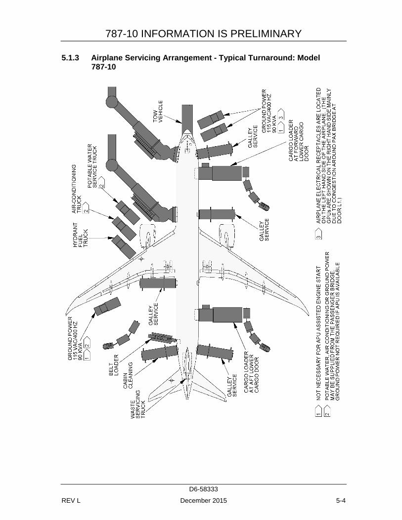
5.1.3 Airplane Servicing Arrangement - Typical Turnaround: Model 787-10
787-10 INFORMATION IS PRELIMINARY
D6-58333
REV L December 2015 5-5
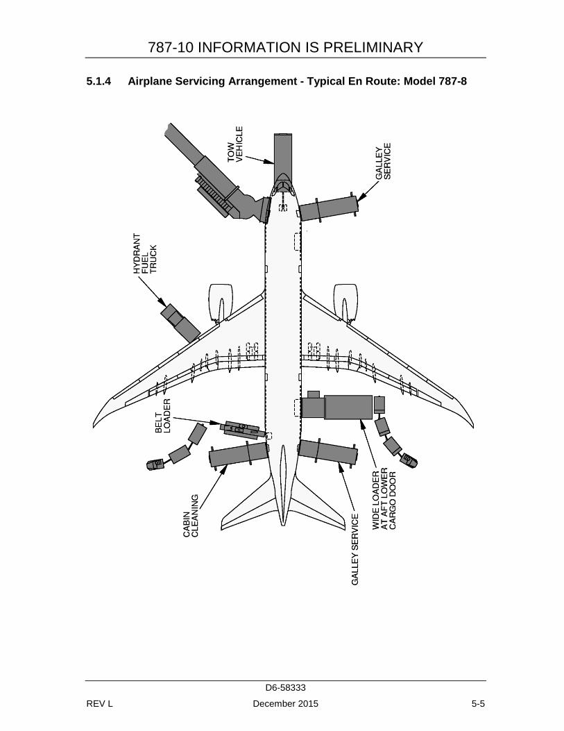
5.1.4 Airplane Servicing Arrangement - Typical En Route: Model 787-8
787-10 INFORMATION IS PRELIMINARY
D6-58333
REV L December 2015 5-6
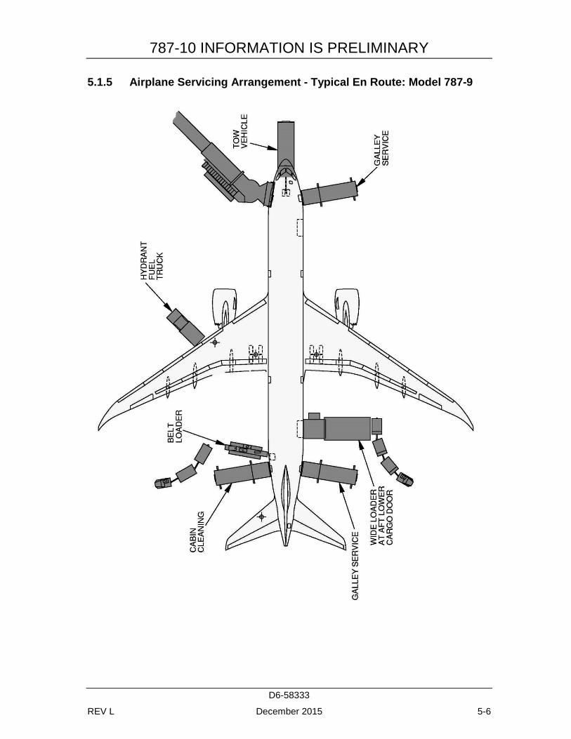
5.1.5 Airplane Servicing Arrangement - Typical En Route: Model 787-9
787-10 INFORMATION IS PRELIMINARY
D6-58333
REV L December 2015 5-7
5.1.6 Airplane Servicing Arrangement - Typical En Route: Model 787-10
787-10 INFORMATION IS PRELIMINARY
D6-58333
REV L December 2015 5-8
5.2 TERMINAL OPERATIONS - TURNAROUND STATION
5.2.1 Terminal Operations, Turntime Analysis - Turnaround Station: Model 787-8
787-10 INFORMATION IS PRELIMINARY
D6-58333
REV L December 2015 5-9
5.2.2 Terminal Operations, Turntime Analysis - Turnaround Station: Model 787-9
787-10 INFORMATION IS PRELIMINARY
D6-58333
REV L December 2015 5-10
5.2.3 Terminal Operations, Turntime Analysis - Turnaround Station: Model 787-10
787-10 INFORMATION IS PRELIMINARY
D6-58333
REV L December 2015 5-11
5.3 TERMINAL OPERATIONS - EN ROUTE STATION
5.3.1 Terminal Operations, Turntime Analysis - En Route Station: Model 787-8
787-10 INFORMATION IS PRELIMINARY
D6-58333
REV L December 2015 5-12
5.3.2 Terminal Operations, Turntime Analysis - En Route Station: Model 787-9

787-10 INFORMATION IS PRELIMINARY
D6-58333
REV L December 2015 5-13
5.3.3 Terminal Operations, Turntime Analysis - En Route Station: Model 787-10
787-10 INFORMATION IS PRELIMINARY
D6-58333
REV L December 2015 5-14
5.4 GROUND SERVICE CONNECTIONS
5.4.1 Ground Service Connections: Model 787-8

787-10 INFORMATION IS PRELIMINARY
D6-58333
REV L December 2015 5-15
5.4.2 Ground Service Connections and Capacities: Model 787-8
SYSTEM MODEL
DISTANCE AFT OF
DISTANCE FROM AIRPLANE CENTERLINE
MAX HEIGHT ABOVE
NOSE LH SIDE RH SIDE GROUND FT M FT M FT M FT M
CONDITIONED AIR ONE 8-IN (20.3 CM) PORT
787-8 71 21.7 3 0.7 - - 7 2.0
ELECTRICAL TWO FORWARD GROUND POWER RECEPTACLES
ONE MID-AFT GROUND POWER RECEPTACLE
ALL RECEPTACLES ARE 90 KVA , 200/115 V AC 400 HZ,
787-8 20 5.9 5 1.4 - - 8 2.5
99 30.3 5 1.6 - - 7 2.2
TWLU ANTENNA LOCATION IS ON THE CENTERLINE
787-8 23 7.1 0 0.0 0 0.0 25 7.7
POTABLE WATER ONE SERVICE CONNECTION
787-8 63 19.3 4 1.1 - - 7 2.2
FUEL ONE UNDERWING- PRESSURE CONNECTOR WITH TWO FUELING
PORTS FUEL VENTS
TOTAL CAPACITY 33,340 US GAL
(126,205 LITERS)
787-8 90 27.5 49 14.8 - - 18 5.4
114 34.6 78 23.7 78 23.7 22 6.6
LAVATORY BOTH FORWARD AND AFT TOILETS ARE SERVICED THROUGH ONE SERVICE PANEL
787-8 144 43.8 0 0.0 0 0.0 10 2.9
787-10 INFORMATION IS PRELIMINARY
D6-58333
REV L December 2015 5-16
5.4.3 Ground Servicing Connections: Model 787-9

787-10 INFORMATION IS PRELIMINARY
D6-58333
REV L December 2015 5-17
5.4.4 Ground Servicing Connections and Capacities: Model 787-9
SYSTEM MODEL
DISTANCE AFT OF
DISTANCE FROM AIRPLANE CENTERLINE
MAX HEIGHT ABOVE
NOSE LH SIDE RH SIDE GROUND FT M FT M FT M FT M
CONDITIONED AIR TWO 8-IN (20.3 CM) PORTS
787-9 81 24.7 3 0.7 3 0.7 7 2.0
ELECTRICAL TWO FORWARD GROUND POWER RECEPTACLES
ONE MID-AFT GROUND POWER RECEPTACLE
ALL RECEPTACLES ARE 90 KVA , 200/115 V AC 400 HZ,
787-9 20 5.9 5 1.4 - - 8 2.5
109 33.3 5 1.6 - - 7 2.2
TWLU ANTENNA LOCATION IS ON THE CENTERLINE
787-9 23 7.1 0 0.0 0 0.0 25 7.7
POTABLE WATER ONE SERVICE CONNECTION
787-9 73 22.4 4 1.1 - - 7 2.3
FUEL ONE UNDERWING- PRESSURE CONNECTOR WITH TWO FUELING
PORTS FUEL VENTS
TOTAL CAPACITY 33,380 US GAL
(126,205 LITERS)
787-9 100 30.5 49 14.8 - - 18 5.4
124 37.6 78 23.7 78 23.7 22 6.6
LAVATORY BOTH FORWARD AND AFT TOILETS ARE SERVICED THROUGH ONE SERVICE PANEL
787-9 164 49.9 0 0.0 0 0.0 8 2.5
787-10 INFORMATION IS PRELIMINARY
D6-58333
REV L December 2015 5-18
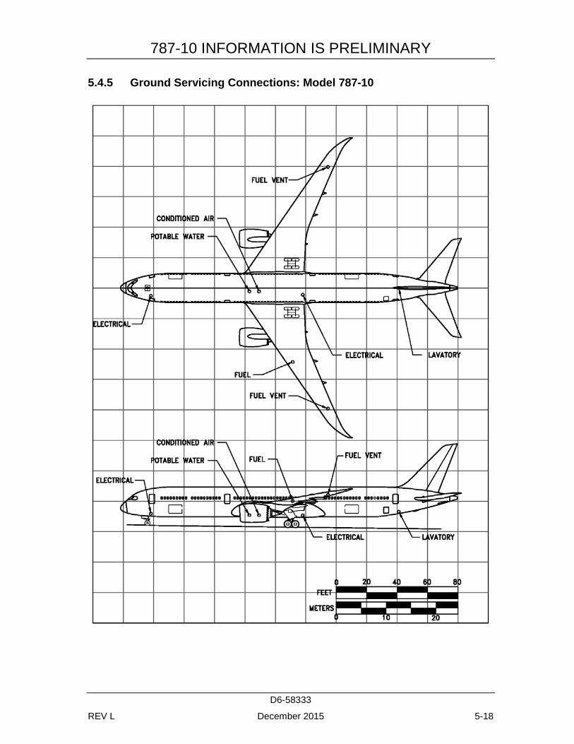
5.4.5 Ground Servicing Connections: Model 787-10
787-10 INFORMATION IS PRELIMINARY
D6-58333
REV L December 2015 5-19
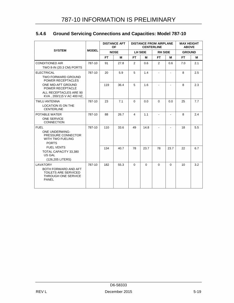
5.4.6 Ground Servicing Connections and Capacities: Model 787-10
SYSTEM MODEL
DISTANCE AFT OF
DISTANCE FROM AIRPLANE CENTERLINE
MAX HEIGHT ABOVE
NOSE LH SIDE RH SIDE GROUND FT M FT M FT M FT M
CONDITIONED AIR TWO 8-IN (20.3 CM) PORTS
787-10 91 27.8 2 0.6 2 0.6 7.0 2.1
ELECTRICAL TWO FORWARD GROUND POWER RECEPTACLES
ONE MID-AFT GROUND POWER RECEPTACLE
ALL RECEPTACLES ARE 90 KVA , 200/115 V AC 400 HZ,
787-10 20 5.9 5 1.4 - - 8 2.5
119 36.4 5 1.6 - - 8 2.3
TWLU ANTENNA LOCATION IS ON THE CENTERLINE
787-10 23 7.1 0 0.0 0 0.0 25 7.7
POTABLE WATER ONE SERVICE CONNECTION
787-10 88 26.7 4 1.1 - - 8 2.4
FUEL ONE UNDERWING- PRESSURE CONNECTOR WITH TWO FUELING
PORTS FUEL VENTS
TOTAL CAPACITY 33,380 US GAL
(126,205 LITERS)
787-10 110 33.6 49 14.8 - - 18 5.5
134 40.7 78 23.7 78 23.7 22 6.7
LAVATORY BOTH FORWARD AND AFT TOILETS ARE SERVICED THROUGH ONE SERVICE PANEL
787-10 182 55.3 0 0 0 0 10 3.2
787-10 INFORMATION IS PRELIMINARY
D6-58333
REV L December 2015 5-20
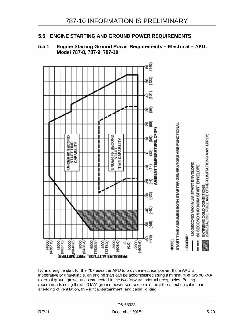
5.5 ENGINE STARTING AND GROUND POWER REQUIREMENTS
5.5.1 Engine Starting Ground Power Requirements – Electrical – APU: Model 787-8, 787-9, 787-10
Normal engine start for the 787 uses the APU to provide electrical power. If the APU is inoperative or unavailable, an engine start can be accomplished using a minimum of two 90 kVA external ground power units connected to the two forward external receptacles. Boeing recommends using three 90 kVA ground power sources to minimize the effect on cabin load shedding of ventilation, In Flight Entertainment, and cabin lighting.
787-10 INFORMATION IS PRELIMINARY
D6-58333
REV L December 2015 5-21
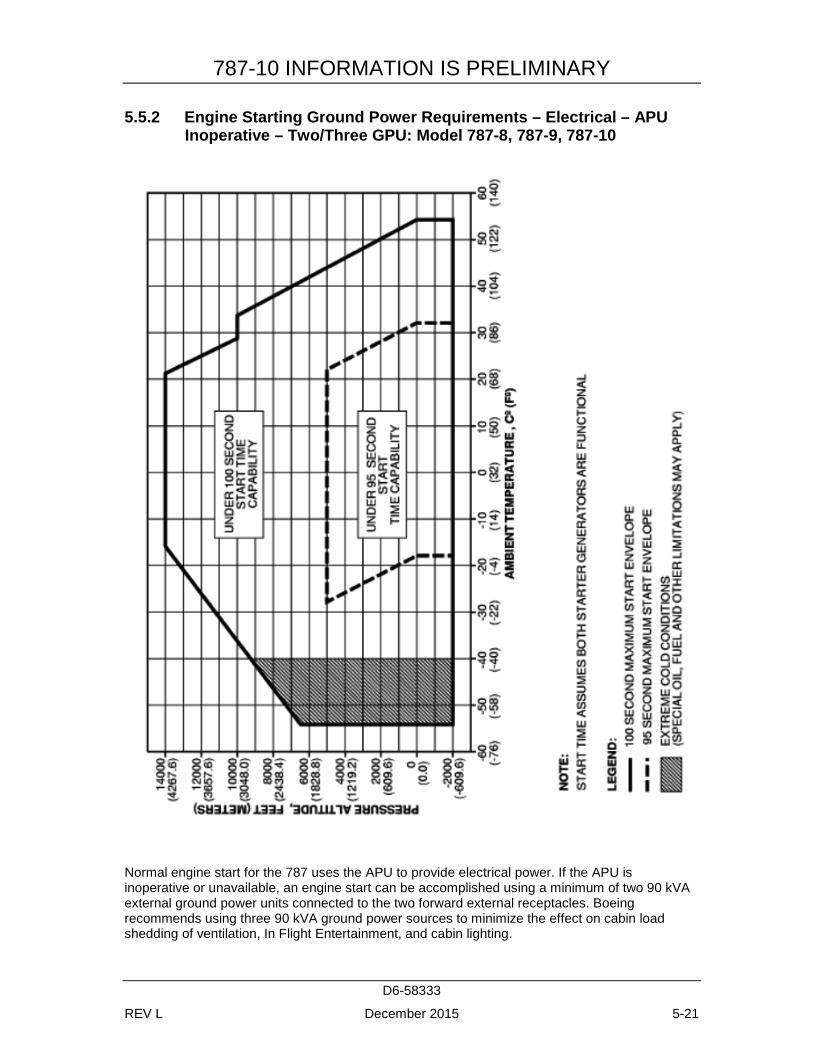
5.5.2 Engine Starting Ground Power Requirements – Electrical – APU Inoperative – Two/Three GPU: Model 787-8, 787-9, 787-10
Normal engine start for the 787 uses the APU to provide electrical power. If the APU is inoperative or unavailable, an engine start can be accomplished using a minimum of two 90 kVA external ground power units connected to the two forward external receptacles. Boeing recommends using three 90 kVA ground power sources to minimize the effect on cabin load shedding of ventilation, In Flight Entertainment, and cabin lighting.
787-10 INFORMATION IS PRELIMINARY
D6-58333
REV L December 2015 5-22
5.5.3 Engine Power Requirements – Pneumatic: Model 787-8, 787-9, 787-10
The 787 aircraft is an electric aircraft and does not
have a traditional pneumatic system onboard,
thus there are no ground pneumatic connections.
787-10 INFORMATION IS PRELIMINARY
D6-58333
REV L December 2015 5-23
5.6 CONDITIONED AIR REQUIREMENTS
5.6.1 Conditioned Air Flow Requirements – Cooling Time: Model 787-8
787-10 INFORMATION IS PRELIMINARY
D6-58333
REV L December 2015 5-24
5.6.2 Conditioned Air Flow Requirements – Cooling – Steady State (103 F Ambient Air): Model 787-8
787-10 INFORMATION IS PRELIMINARY
D6-58333
REV L December 2015 5-25
5.6.3 Conditioned Air Flow Requirements – Cooling – Steady State (80 F Ambient Air): Model 787-8
787-10 INFORMATION IS PRELIMINARY
D6-58333
REV L December 2015 5-26
5.6.4 Conditioned Air Flow Requirements – Heating Time: Model 787-8
787-10 INFORMATION IS PRELIMINARY
D6-58333
REV L December 2015 5-27
5.6.5 Conditioned Air Flow Requirements – Heating – Steady State: Model 787-8
787-10 INFORMATION IS PRELIMINARY
D6-58333
REV L December 2015 5-28
5.6.6 Conditioned Air Flow Requirements – Cooling Time: Model 787-9
787-10 INFORMATION IS PRELIMINARY
D6-58333
REV L December 2015 5-29
5.6.7 Conditioned Air Flow Requirements – Cooling – Steady State (103 F Ambient Air): Model 787-9
787-10 INFORMATION IS PRELIMINARY
D6-58333
REV L December 2015 5-30
5.6.8 Conditioned Air Flow Requirements – Cooling – Steady State (80 F Ambient Air): Model 787-9
787-10 INFORMATION IS PRELIMINARY
D6-58333
REV L December 2015 5-31
5.6.9 Conditioned Air Flow Requirements – Heating Time: Model 787-9
787-10 INFORMATION IS PRELIMINARY
D6-58333
REV L December 2015 5-32
5.6.10 Conditioned Air Flow Requirements – Heating – Steady State: Model 787-9
787-10 INFORMATION IS PRELIMINARY
D6-58333
REV L December 2015 5-33
5.6.11 Conditioned Air Flow Requirements: Model 787-10
DATA TO BE PROVIDED AT A LATER DATE
787-10 INFORMATION IS PRELIMINARY
D6-58333
REV L December 2015 5-34
5.7 GROUND TOWING REQUIREMENTS
5.7.1 Ground Towing Requirements - English Units: Model 787-8, 787-9, 787-10
787-10 INFORMATION IS PRELIMINARY
D6-58333
REV L December 2015 5-35
5.7.2 Ground Towing Requirements - Metric Units: Model 787-8, 787-9, 787-10
787-10 INFORMATION IS PRELIMINARY
D6-58333
REV L December 2015 6-1
6.0 JET ENGINE WAKE AND NOISE DATA
6.1 JET ENGINE EXHAUST VELOCITIES AND TEMPERATURE
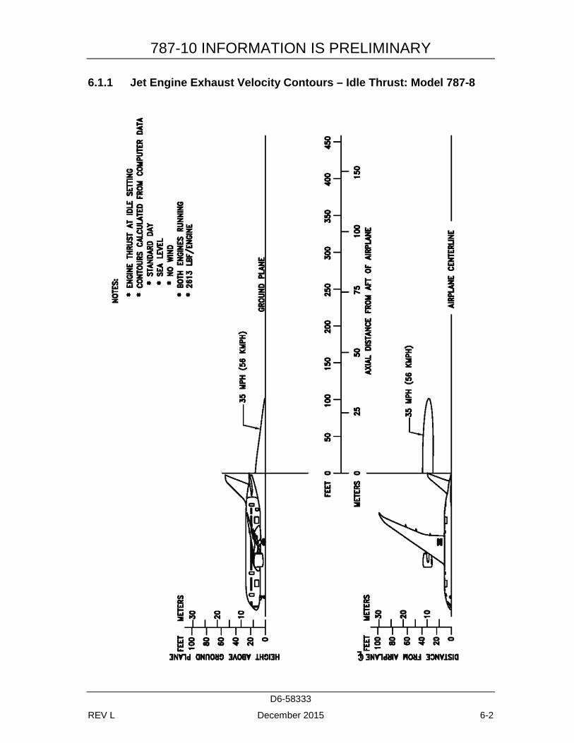
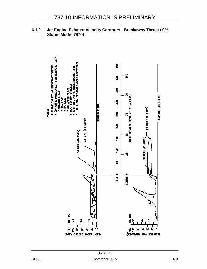
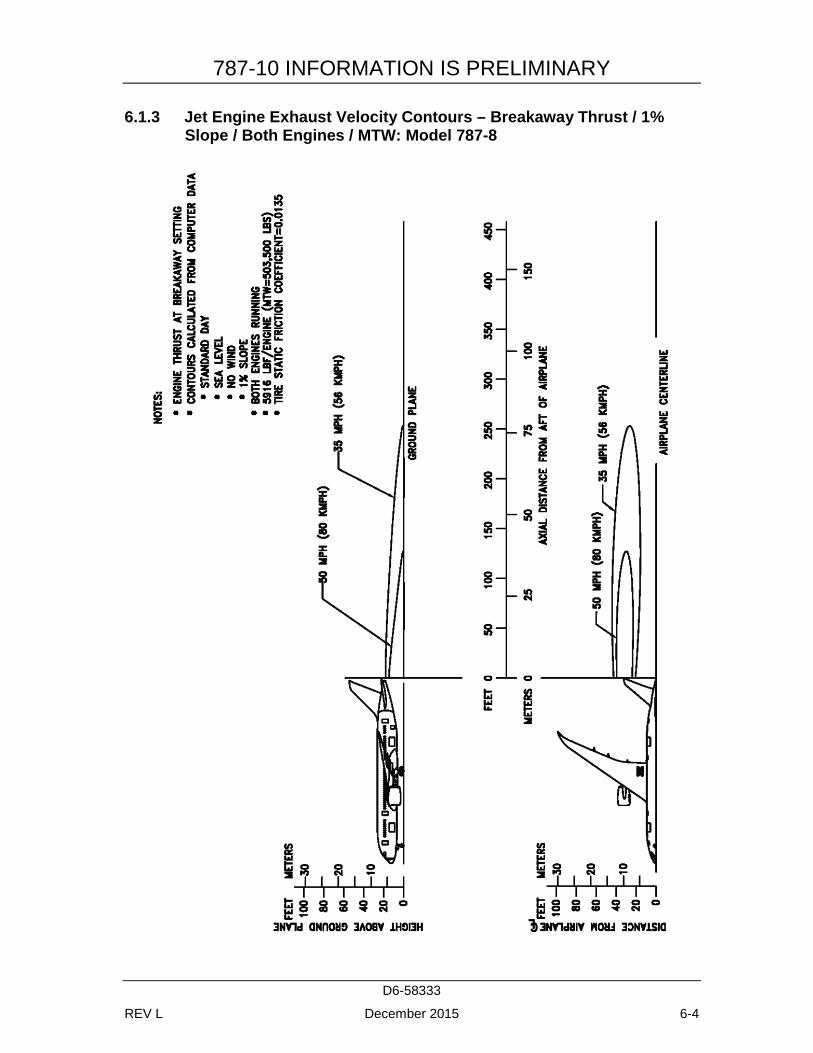
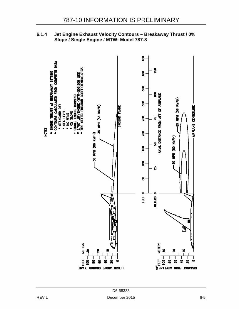
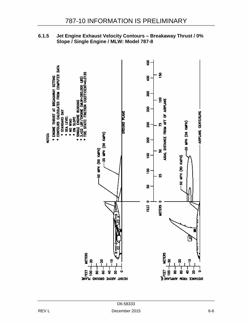
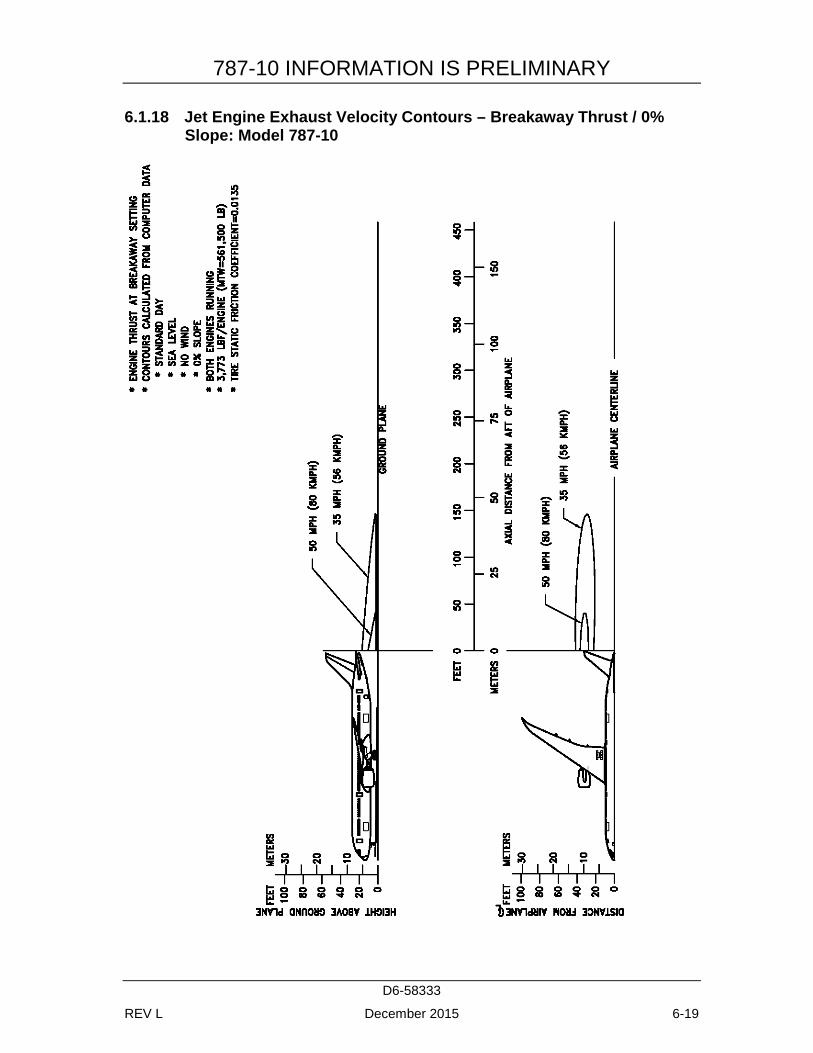
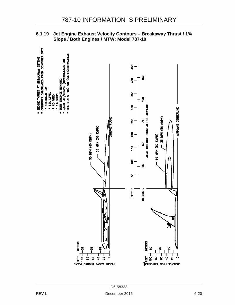
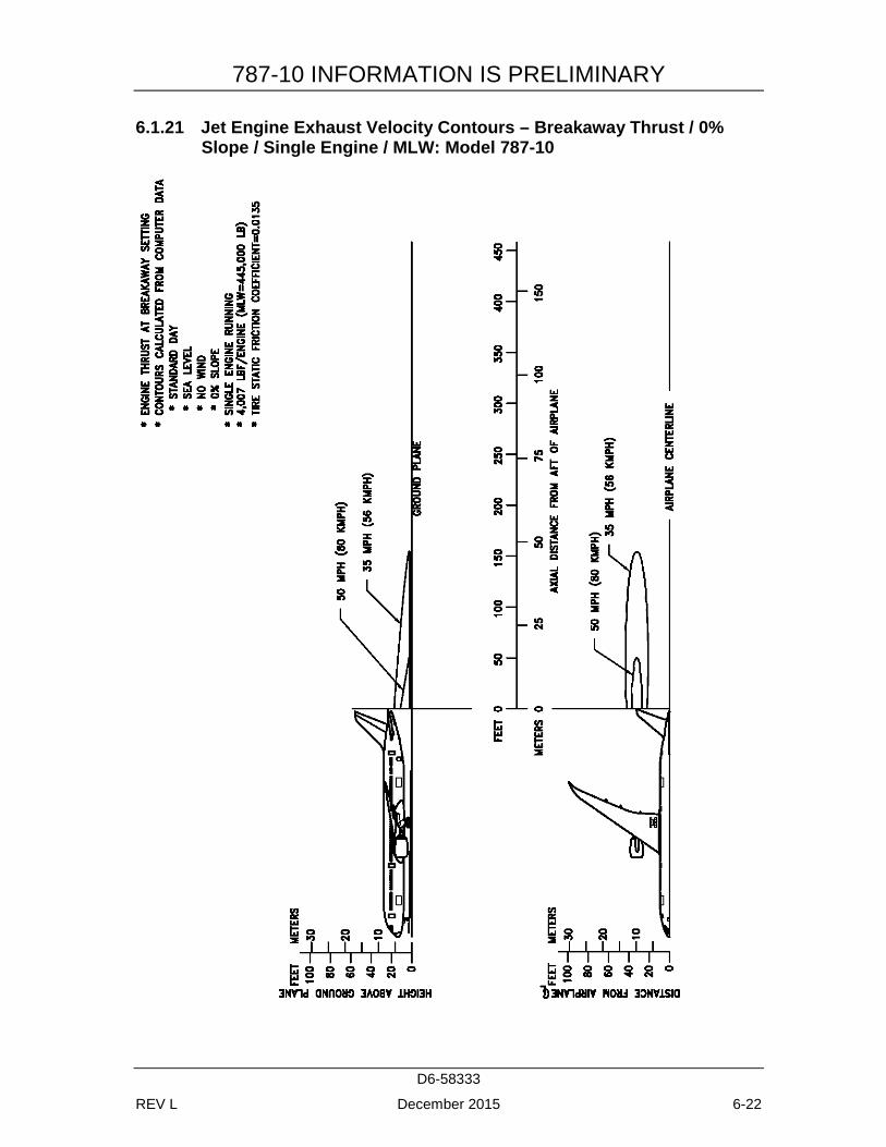
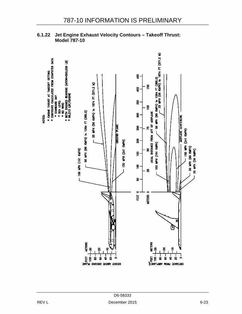
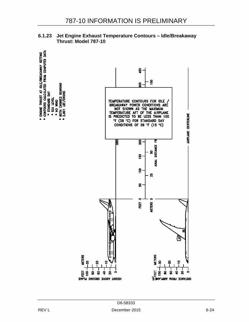
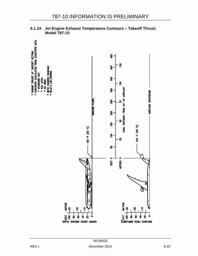
This section shows exhaust velocity and temperature contours aft of the 787 airplane. The contours were calculated from a standard computer analysis using three-dimensional viscous flow equations with mixing of primary, fan, and free-stream flow. The presence of the ground plane is included in the calculations as well as engine tilt and toe-in. Mixing of flows from the engines is also calculated. The analysis does not include thermal buoyancy effects which tend to elevate the jet wake above the ground plane. The buoyancy effects are considered to be small relative to the exhaust velocity and therefore are not included.
The graphs show jet wake velocity and temperature contours for representative engines. The results are valid for sea level, static, standard day conditions. The effect of wind on jet wakes is not included. There is evidence to show that a downwind or an upwind component does not simply add or subtract from the jet wake velocity, but rather carries the whole envelope in the direction of the wind. Crosswinds may carry the jet wake contour far to the side at large distances behind the airplane.
It should be understood, these exhaust velocity contours reflect steady-state, at maximum taxi weight, and not transient-state exhaust velocities. A steady-state is achieved with the aircraft in a fixed location, engine running at a given thrust level and measured when the contours stop expanding and stabilize in size, which could take several seconds. The steady-state condition, therefore, is conservative. Contours shown also do not account for performance variables such as ambient temperature or field elevation. For the terminal area environment, the transient-state is a more accurate representation of the actual exhaust contours when the aircraft is in motion and encountering static air with forward or turning movement, but it is very difficult to model on a consistent basis due to aircraft weight, weather conditions, the high degree of variability in terminal and apron configurations, and intensive numerical calculations. If the contours presented here are overly restrictive for terminal operations, The Boeing Company recommends conducting an analysis of the actual exhaust contours experienced by the using aircraft at the airport.
787-10 INFORMATION IS PRELIMINARY
D6-58333
REV L December 2015 6-2
6.1.1 Jet Engine Exhaust Velocity Contours – Idle Thrust: Model 787-8
787-10 INFORMATION IS PRELIMINARY
D6-58333
REV L December 2015 6-3
6.1.2 Jet Engine Exhaust Velocity Contours - Breakaway Thrust / 0% Slope: Model 787-8
787-10 INFORMATION IS PRELIMINARY
D6-58333
REV L December 2015 6-4
6.1.3 Jet Engine Exhaust Velocity Contours – Breakaway Thrust / 1% Slope / Both Engines / MTW: Model 787-8
787-10 INFORMATION IS PRELIMINARY
D6-58333
REV L December 2015 6-5
6.1.4 Jet Engine Exhaust Velocity Contours – Breakaway Thrust / 0% Slope / Single Engine / MTW: Model 787-8
787-10 INFORMATION IS PRELIMINARY
D6-58333
REV L December 2015 6-6
6.1.5 Jet Engine Exhaust Velocity Contours – Breakaway Thrust / 0% Slope / Single Engine / MLW: Model 787-8
787-10 INFORMATION IS PRELIMINARY
D6-58333
REV L December 2015 6-7
6.1.6 Jet Engine Exhaust Velocity Contours – Takeoff Thrust: Model 787-8
787-10 INFORMATION IS PRELIMINARY
D6-58333
REV L December 2015 6-8
6.1.7 Jet Engine Exhaust Temperature Contours – Idle/Breakaway Thrust: Model 787-8
787-10 INFORMATION IS PRELIMINARY
D6-58333
REV L December 2015 6-9
6.1.8 Jet Engine Exhaust Temperature Contours – Takeoff Thrust: Model 787-8
787-10 INFORMATION IS PRELIMINARY
D6-58333
REV L December 2015 6-10
6.1.9 Jet Engine Exhaust Velocity Contours – Idle Thrust: Model 787-9
787-10 INFORMATION IS PRELIMINARY
D6-58333
REV L December 2015 6-11
6.1.10 Jet Engine Exhaust Velocity Contours – Breakaway Thrust / 0% Slope: Model 787-9
787-10 INFORMATION IS PRELIMINARY
D6-58333
REV L December 2015 6-12
6.1.11 Jet Engine Exhaust Velocity Contours – Breakaway Thrust / 1% Slope / Both Engines / MTW: Model 787-9
787-10 INFORMATION IS PRELIMINARY
D6-58333
REV L December 2015 6-13
6.1.12 Jet Engine Exhaust Velocity Contours – Breakaway Thrust / 0% Slope / Single Engine / MTW: Model 787-9
787-10 INFORMATION IS PRELIMINARY
D6-58333
REV L December 2015 6-14
6.1.13 Jet Engine Exhaust Velocity Contours – Breakaway Thrust / 0% Slope / Single Engine / MLW: Model 787-9
787-10 INFORMATION IS PRELIMINARY
D6-58333
REV L December 2015 6-15
6.1.14 Jet Engine Exhaust Velocity Contours – Takeoff Thrust: Model 787-9
787-10 INFORMATION IS PRELIMINARY
D6-58333
REV L December 2015 6-16
6.1.15 Jet Engine Exhaust Temperature Contours – Idle/Breakaway Thrust: Model 787-9
787-10 INFORMATION IS PRELIMINARY
D6-58333
REV L December 2015 6-17
6.1.16 Jet Engine Exhaust Temperature Contours – Takeoff Thrust: Model 787-9
787-10 INFORMATION IS PRELIMINARY
D6-58333
REV L December 2015 6-18
6.1.17 Jet Engine Exhaust Velocity Contours – Idle Thrust: Model 787-10
787-10 INFORMATION IS PRELIMINARY
D6-58333
REV L December 2015 6-19
6.1.18 Jet Engine Exhaust Velocity Contours – Breakaway Thrust / 0% Slope: Model 787-10
787-10 INFORMATION IS PRELIMINARY
D6-58333
REV L December 2015 6-20
6.1.19 Jet Engine Exhaust Velocity Contours – Breakaway Thrust / 1% Slope / Both Engines / MTW: Model 787-10

787-10 INFORMATION IS PRELIMINARY
D6-58333
REV L December 2015 6-21
6.1.20 Jet Engine Exhaust Velocity Contours – Breakaway Thrust / 0% Slope / Single Engine / MTW: Model 787-10
787-10 INFORMATION IS PRELIMINARY
D6-58333
REV L December 2015 6-22
6.1.21 Jet Engine Exhaust Velocity Contours – Breakaway Thrust / 0% Slope / Single Engine / MLW: Model 787-10
787-10 INFORMATION IS PRELIMINARY
D6-58333
REV L December 2015 6-23
6.1.22 Jet Engine Exhaust Velocity Contours – Takeoff Thrust: Model 787-10
787-10 INFORMATION IS PRELIMINARY
D6-58333
REV L December 2015 6-24
6.1.23 Jet Engine Exhaust Temperature Contours – Idle/Breakaway Thrust: Model 787-10
787-10 INFORMATION IS PRELIMINARY
D6-58333
REV L December 2015 6-25
6.1.24 Jet Engine Exhaust Temperature Contours – Takeoff Thrust: Model 787-10
787-10 INFORMATION IS PRELIMINARY
D6-58333
REV L December 2015 6-26
6.2 AIRPORT AND COMMUNITY NOISE
Airport noise is of major concern to the airport and community planner. The airport is a major element in the community's transportation system and, as such, is vital to its growth. However, the airport must also be a good neighbor, and this can be accomplished only with proper planning. Since aircraft noise extends beyond the boundaries of the airport, it is vital to consider the impact on surrounding communities. Many means have been devised to provide the planner with a tool to estimate the impact of airport operations. Too often they oversimplify noise to the point where the results become erroneous. Noise is not a simple subject; therefore, there are no simple answers.
The cumulative noise contour is an effective tool. However, care must be exercised to ensure that the contours, used correctly, estimate the noise resulting from aircraft operations conducted at an airport.
The size and shape of the single-event contours, which are inputs into the cumulative noise contours, are dependent upon numerous factors. They include the following:
1. Operational Factors
a. Aircraft Weight - Aircraft weight is dependent on distance to be traveled, en route winds, payload, and anticipated aircraft delay upon reaching the destination.
b. Engine Power Settings - The rates of ascent and descent and the noise levels emitted at the source are influenced by the power setting used.
c. Airport Altitude - Higher airport altitude will affect engine performance and thus can influence noise.
2. Atmospheric Conditions-Sound Propagation
a. Wind - With stronger headwinds, the aircraft can take off and climb more rapidly relative to the ground. Also, winds can influence the distribution of noise in surrounding communities.
b. Temperature and Relative Humidity - The absorption of noise in the atmosphere along the transmission path between the aircraft and the ground observer varies with both temperature and relative humidity.
3. Surface Condition-Shielding, Extra Ground Attenuation (EGA)
a. Terrain - If the ground slopes down after takeoff or up before landing, noise will be reduced since the aircraft will be at a higher altitude above ground. Additionally, hills, shrubs, trees, and large buildings can act as sound buffers.
787-10 INFORMATION IS PRELIMINARY
D6-58333
REV L December 2015 6-27
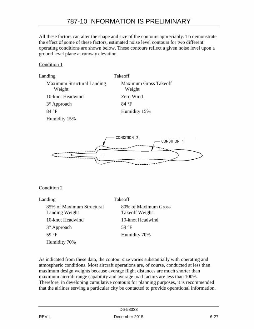
All these factors can alter the shape and size of the contours appreciably. To demonstrate the effect of some of these factors, estimated noise level contours for two different operating conditions are shown below. These contours reflect a given noise level upon a ground level plane at runway elevation.
Condition 1
Landing Takeoff Maximum Structural Landing
Weight Maximum Gross Takeoff
Weight 10-knot Headwind Zero Wind 3° Approach 84 °F 84 °F Humidity 15% Humidity 15%
Condition 2
Landing Takeoff 85% of Maximum Structural Landing Weight
80% of Maximum Gross Takeoff Weight
10-knot Headwind 10-knot Headwind 3° Approach 59 °F 59 °F Humidity 70% Humidity 70%
As indicated from these data, the contour size varies substantially with operating and atmospheric conditions. Most aircraft operations are, of course, conducted at less than maximum design weights because average flight distances are much shorter than maximum aircraft range capability and average load factors are less than 100%. Therefore, in developing cumulative contours for planning purposes, it is recommended that the airlines serving a particular city be contacted to provide operational information.
787-10 INFORMATION IS PRELIMINARY
D6-58333
REV L December 2015 6-28
In addition, there are no universally accepted methods for developing aircraft noise contours or for relating the acceptability of specific zones to specific land uses. It is therefore expected that noise contour data for particular aircraft and the impact assessment methodology will be changing. To ensure that the best currently available information of this type is used in any planning study, it is recommended that it be obtained directly from the Office of Environmental Quality in the Federal Aviation Administration in Washington, D.C.
It should be noted that the contours shown herein are only for illustrating the impact of operating and atmospheric conditions and do not represent the single-event contour of the family of aircraft described in this document. It is expected that the cumulative contours will be developed as required by planners using the data and methodology applicable to their specific study.
787-10 INFORMATION IS PRELIMINARY
D6-58333
REV L December 2015 7-1
7.0 PAVEMENT DATA
7.1 GENERAL INFORMATION
A brief description of the pavement charts that follow will help in their use for airport planning. Each airplane configuration is depicted with a minimum range of five loads imposed on the main landing gear to aid in interpolation between the discrete values shown. All curves for any single chart represent data based on rated loads and tire pressures considered normal and acceptable by current aircraft tire manufacturer's standards. Tire pressures, where specifically designated on tables and charts, are at values obtained under loaded conditions as certificated for commercial use.
Section 7.2 presents basic data on the landing gear footprint configuration, maximum design taxi loads, and tire sizes and pressures.
Maximum pavement loads for certain critical conditions at the tire-to-ground interface are shown in Section 7.3, with the tires having equal loads on the struts.
Pavement requirements for commercial airplanes are customarily derived from the static analysis of loads imposed on the main landing gear struts. The charts in Section 7.4 are provided in order to determine these loads throughout the stability limits of the airplane at rest on the pavement. These main landing gear loads are used as the point of entry to the pavement design charts, interpolating load values where necessary.
The flexible pavement design curves (Section 7.5) are based on procedures set forth in Instruction Report No. S-77-1, "Procedures for Development of CBR Design Curves," dated June 1977, and as modified according to the methods described in ICAO Aerodrome Design Manual, Part 3, Pavements, 2nd Edition, 1983, Section 1.1 (The ACN-PCN Method), and utilizing the alpha factors approved by ICAO in October 2007. Instruction Report No. S-77-1 was prepared by the U.S. Army Corps of Engineers Waterways Experiment Station, Soils and Pavements Laboratory, Vicksburg, Mississippi. The line showing 10,000 coverages is used to calculate Aircraft Classification Number (ACN).
The following procedure is used to develop the curves, such as shown in Section 7.5:
1. Having established the scale for pavement depth at the bottom and the scale for CBR at the top, an arbitrary line is drawn representing 6,000 annual departures.
2. Values of the aircraft gross weight are then plotted.
3. Additional annual departure lines are drawn based on the load lines of the aircraft gross weights already established.
4. An additional line representing 10,000 coverages (used to calculate the flexible pavement Aircraft Classification Number) is also placed.
787-10 INFORMATION IS PRELIMINARY
D6-58333
REV L December 2015 7-2
The Load Classification Number (LCN) curves are no longer provided in section 7.6 and 7.8 since the LCN system for reporting pavement strength is obsolete, being replaced by the ICAO recommended ACN/PCN system in 1983. For questions regarding the LCN system contact Boeing Airport Compatibility Engineering:
Rigid pavement design curves (Section 7.7) have been prepared with the Westergaard equation in general accordance with the procedures outlined in the Design of Concrete Airport Pavement (1995 edition) by Robert G. Packard, published by the Portland Cement Association, 5420 Old Orchard Road, Skokie, Illinois 60077-1059. These curves are modified to the format described in the Portland Cement Association publication XP6705-2, Computer Program for Airport Pavement Design (Program PDILB), 1968, by Robert G. Packard.
The following procedure is used to develop the rigid pavement design curves shown in Section 7.7:
1. Having established the scale for pavement thickness to the left and the scale for allowable working stress to the right, an arbitrary load line is drawn representing the main landing gear maximum weight to be shown.
2. Values of the subgrade modulus (k) are then plotted.
3. Additional load lines for the incremental values of weight on the main landing gear are drawn on the basis of the curve for k = 300, already established.
For the rigid pavement design (Section 7.9) refer to the FAA website for the FAA design software COMFAA:
http://www.faa.gov/airports/engineering/design_software/
The ACN/PCN system (Section 7.10) as referenced in ICAO Annex 14, "Aerodromes," Sixth Edition, July 2013, provides a standardized international airplane/pavement rating system replacing the various S, T, TT, LCN, AUW, ISWL, etc., rating systems used throughout the world. ACN is the Aircraft Classification Number and PCN is the Pavement Classification Number. An aircraft having an ACN equal to or less than the PCN can operate without restriction on the pavement subject to any limitation on the tire pressure. Numerically, the ACN is two times the derived single-wheel load expressed in thousands of kilograms, where the derived single wheel load is defined as the load on a single tire inflated to 181 psi (1.25 MPa) that would have the same pavement requirements as the aircraft. Computationally, the ACN/PCN system uses the PCA program PDILB for rigid pavements and S-77-1 for flexible pavements to calculate ACN values. The method of pavement evaluation is left up to the airport with the results of their evaluation presented as follows:
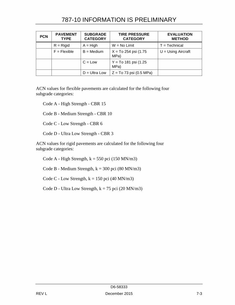
787-10 INFORMATION IS PRELIMINARY
D6-58333
REV L December 2015 7-3
PCN PAVEMENT TYPE
SUBGRADE CATEGORY
TIRE PRESSURE CATEGORY
EVALUATION METHOD
R = Rigid A = High W = No Limit T = Technical F = Flexible B = Medium X = To 254 psi (1.75
MPa) U = Using Aircraft
C = Low Y = To 181 psi (1.25 MPa)
D = Ultra Low Z = To 73 psi (0.5 MPa)
ACN values for flexible pavements are calculated for the following four subgrade categories:
Code A - High Strength - CBR 15
Code B - Medium Strength - CBR 10
Code C - Low Strength - CBR 6
Code D - Ultra Low Strength - CBR 3
ACN values for rigid pavements are calculated for the following four subgrade categories:
Code A - High Strength, k = 550 pci (150 MN/m3)
Code B - Medium Strength, k = 300 pci (80 MN/m3)
Code C - Low Strength, k = 150 pci (40 MN/m3)
Code D - Ultra Low Strength, k = 75 pci (20 MN/m3)
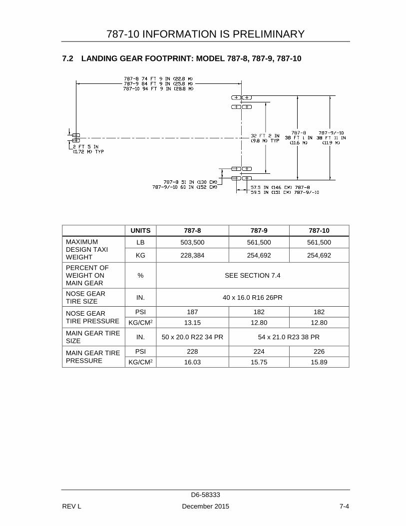
787-10 INFORMATION IS PRELIMINARY
D6-58333
REV L December 2015 7-4
7.2 LANDING GEAR FOOTPRINT: MODEL 787-8, 787-9, 787-10
UNITS 787-8 787-9 787-10 MAXIMUM DESIGN TAXI WEIGHT
LB 503,500 561,500 561,500
KG 228,384 254,692 254,692
PERCENT OF WEIGHT ON MAIN GEAR
% SEE SECTION 7.4
NOSE GEAR TIRE SIZE IN. 40 x 16.0 R16 26PR
NOSE GEAR TIRE PRESSURE
PSI 187 182 182 KG/CM2 13.15 12.80 12.80
MAIN GEAR TIRE SIZE IN. 50 x 20.0 R22 34 PR 54 x 21.0 R23 38 PR
MAIN GEAR TIRE PRESSURE
PSI 228 224 226 KG/CM2 16.03 15.75 15.89
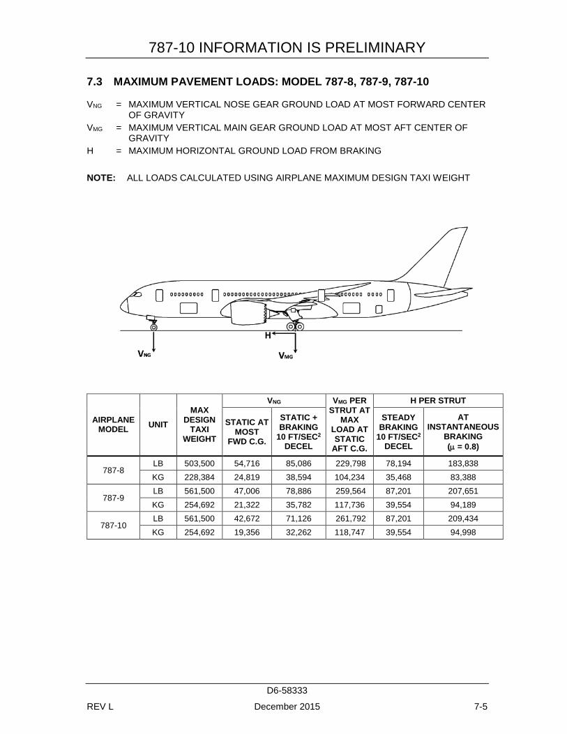
787-10 INFORMATION IS PRELIMINARY
D6-58333
REV L December 2015 7-5
7.3 MAXIMUM PAVEMENT LOADS: MODEL 787-8, 787-9, 787-10
VNG = MAXIMUM VERTICAL NOSE GEAR GROUND LOAD AT MOST FORWARD CENTER OF GRAVITY
VMG = MAXIMUM VERTICAL MAIN GEAR GROUND LOAD AT MOST AFT CENTER OF GRAVITY
H = MAXIMUM HORIZONTAL GROUND LOAD FROM BRAKING NOTE: ALL LOADS CALCULATED USING AIRPLANE MAXIMUM DESIGN TAXI WEIGHT
AIRPLANE MODEL UNIT
MAX DESIGN
TAXI WEIGHT
VNG VMG PER STRUT AT
MAX LOAD AT STATIC
AFT C.G.
H PER STRUT
STATIC AT MOST
FWD C.G.
STATIC + BRAKING
10 FT/SEC2 DECEL
STEADY BRAKING
10 FT/SEC2 DECEL
AT INSTANTANEOUS
BRAKING (µ = 0.8)
787-8 LB 503,500 54,716 85,086 229,798 78,194 183,838 KG 228,384 24,819 38,594 104,234 35,468 83,388
787-9 LB 561,500 47,006 78,886 259,564 87,201 207,651 KG 254,692 21,322 35,782 117,736 39,554 94,189
787-10 LB 561,500 42,672 71,126 261,792 87,201 209,434 KG 254,692 19,356 32,262 118,747 39,554 94,998
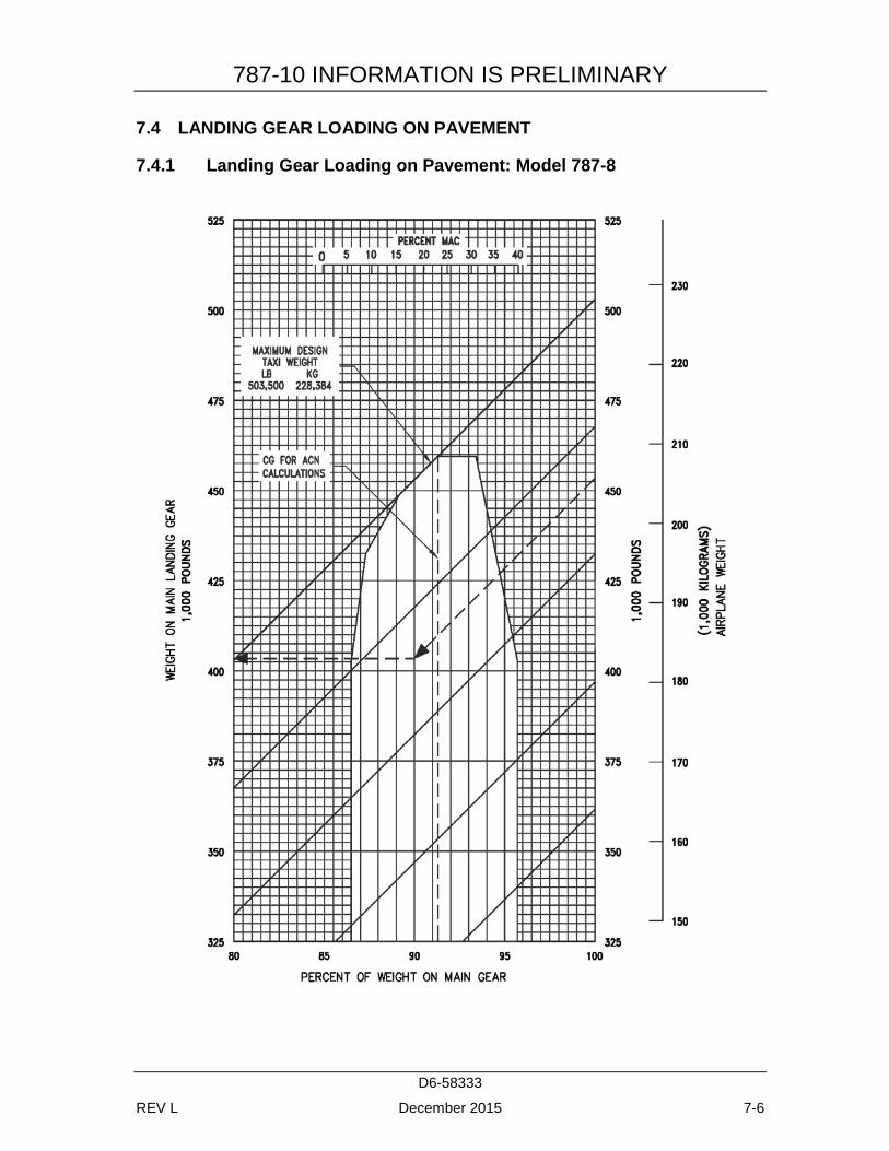
787-10 INFORMATION IS PRELIMINARY
D6-58333
REV L December 2015 7-6
7.4 LANDING GEAR LOADING ON PAVEMENT
7.4.1 Landing Gear Loading on Pavement: Model 787-8
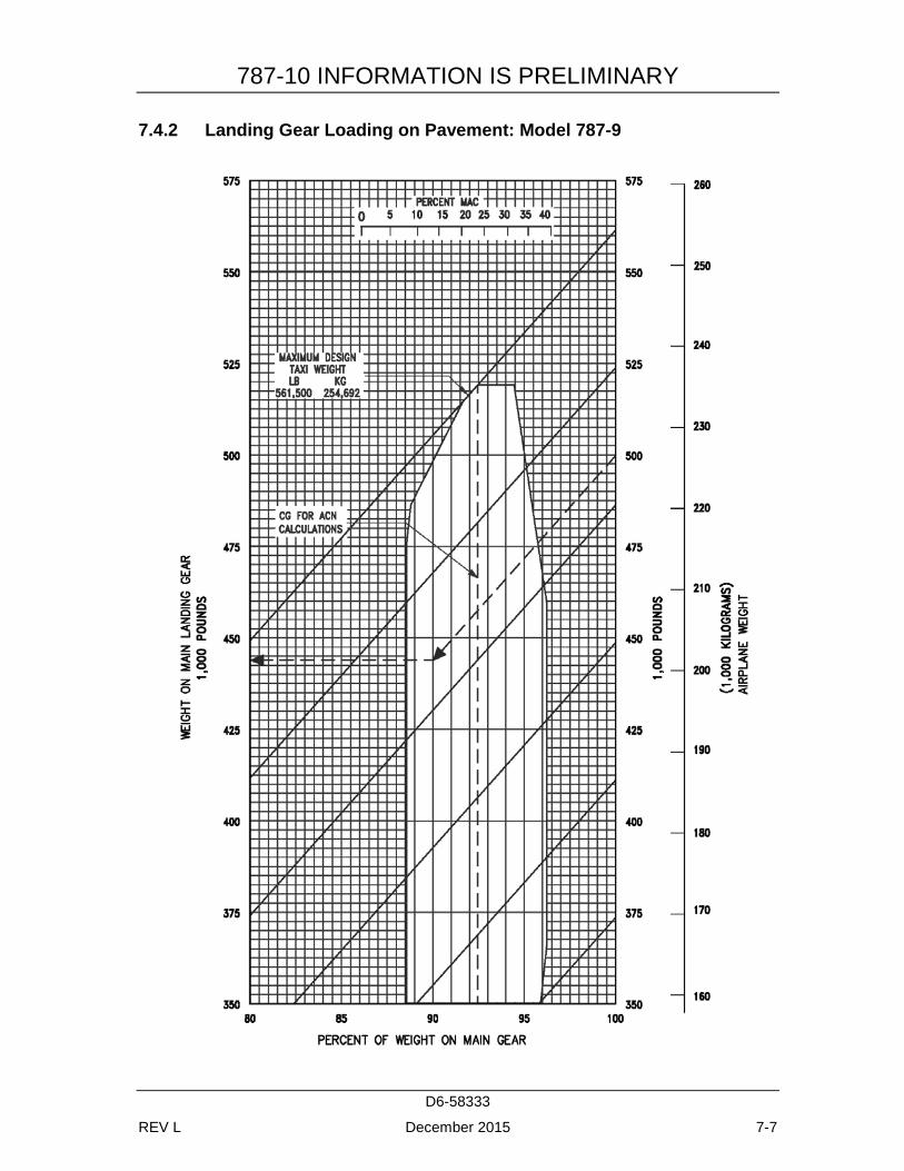
787-10 INFORMATION IS PRELIMINARY
D6-58333
REV L December 2015 7-7
7.4.2 Landing Gear Loading on Pavement: Model 787-9
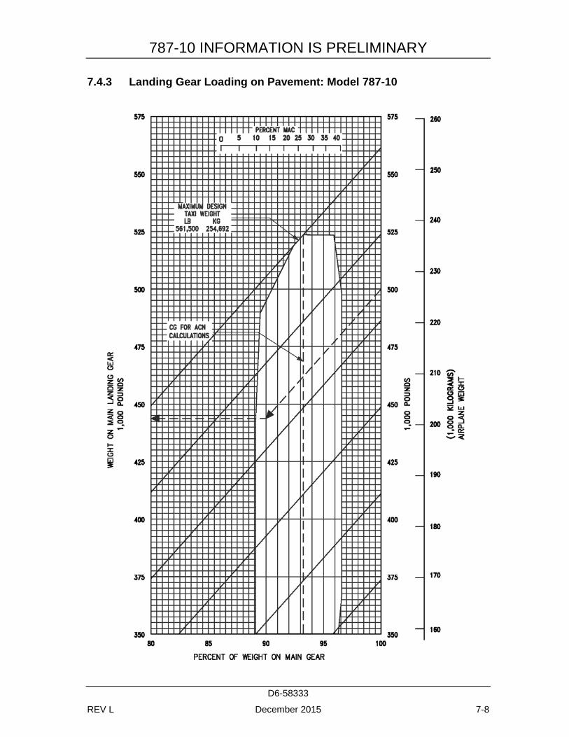
787-10 INFORMATION IS PRELIMINARY
D6-58333
REV L December 2015 7-8
7.4.3 Landing Gear Loading on Pavement: Model 787-10
787-10 INFORMATION IS PRELIMINARY
D6-58333
REV L December 2015 7-9
7.5 FLEXIBLE PAVEMENT REQUIREMENTS - U.S. ARMY CORPS OF ENGINEERS METHOD S-77-1
The following flexible-pavement design chart presents the data of five incremental main-gear loads at the minimum tire pressure required at the maximum design taxi weight.
In the example shown in 7.5.1, for a CBR of 25 and an annual departure level of 25,000, the required flexible pavement thickness for an airplane with a main gear loading of 300,000 pounds is 12.6 inches.
The line showing 10,000 coverages is used for ACN calculations (see Section 7.10).
The traditional FAA design method used a similar procedure using total airplane weight instead of weight on the main landing gears. The equivalent main gear loads for a given airplane weight could be calculated from Section 7.4.
787-10 INFORMATION IS PRELIMINARY
D6-58333
REV L December 2015 7-10
7.5.1 Flexible Pavement Requirements - U.S. Army Corps of Engineers Design Method (S-77-1): Model 787-8
DATA TO BE PROVIDED AT A LATER DATE
787-10 INFORMATION IS PRELIMINARY
D6-58333
REV L December 2015 7-11
7.5.2 Flexible Pavement Requirements - U.S. Army Corps of Engineers Design Method (S-77-1): Model 787-9
DATA TO BE PROVIDED AT A LATER DATE

787-10 INFORMATION IS PRELIMINARY
D6-58333
REV L December 2015 7-12
7.5.3 Flexible Pavement Requirements - U.S. Army Corps of Engineers Design Method (S-77-1): Model 787-10
DATA TO BE PROVIDED AT A LATER DATE
787-10 INFORMATION IS PRELIMINARY
D6-58333
REV L December 2015 7-13
7.6 FLEXIBLE PAVEMENT REQUIREMENTS - LCN METHOD
The Load Classification Number (LCN) curves are no longer provided in section 7.6 and 7.8 since the LCN system for reporting pavement strength is obsolete, being replaced by the ICAO recommended ACN/PCN system in 1983. For questions regarding the LCN system contact Boeing Airport Compatibility Engineering:
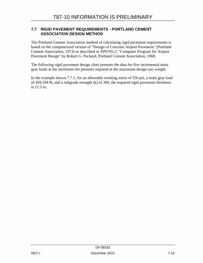
787-10 INFORMATION IS PRELIMINARY
D6-58333
REV L December 2015 7-14
7.7 RIGID PAVEMENT REQUIREMENTS - PORTLAND CEMENT ASSOCIATION DESIGN METHOD
The Portland Cement Association method of calculating rigid pavement requirements is based on the computerized version of "Design of Concrete Airport Pavement" (Portland Cement Association, 1973) as described in XP6705-2, "Computer Program for Airport Pavement Design" by Robert G. Packard, Portland Cement Association, 1968.
The following rigid pavement design chart presents the data for five incremental main gear loads at the minimum tire pressure required at the maximum design taxi weight.
In the example shown 7.7.1, for an allowable working stress of 550 psi, a main gear load of 459,594 lb, and a subgrade strength (k) of 300, the required rigid pavement thickness is 11.3 in.

787-10 INFORMATION IS PRELIMINARY
D6-58333
REV L December 2015 7-15
7.7.1 Rigid Pavement Requirements - Portland Cement Association Design Method: Model 787-8
DATA TO BE PROVIDED AT A LATER DATE
787-10 INFORMATION IS PRELIMINARY
D6-58333
REV L December 2015 7-16
7.7.2 Rigid Pavement Requirements - Portland Cement Association Design Method: Model 787-9
DATA TO BE PROVIDED AT A LATER DATE

787-10 INFORMATION IS PRELIMINARY
D6-58333
REV L December 2015 7-17
7.7.3 Rigid Pavement Requirements - Portland Cement Association Design Method: Model 787-10
DATA TO BE PROVIDED AT A LATER DATE
787-10 INFORMATION IS PRELIMINARY
D6-58333
REV L December 2015 7-18
7.8 RIGID PAVEMENT REQUIREMENTS - LCN CONVERSION
The Load Classification Number (LCN) curves are no longer provided in section 7.6 and 7.8 since the LCN system for reporting pavement strength is obsolete, being replaced by the ICAO recommended ACN/PCN system in 1983. For questions regarding the LCN system contact Boeing Airport Compatibility Engineering:
787-10 INFORMATION IS PRELIMINARY
D6-58333
REV L December 2015 7-19
7.9 RIGID PAVEMENT REQUIREMENTS - FAA DESIGN METHOD
For the rigid pavement design refer to the FAA website for the FAA design software COMFAA:
http://www.faa.gov/airports/engineering/design_software/
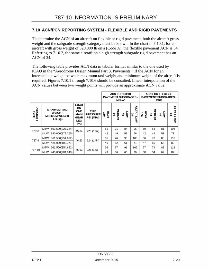
787-10 INFORMATION IS PRELIMINARY
D6-58333
REV L December 2015 7-20
7.10 ACN/PCN REPORTING SYSTEM - FLEXIBLE AND RIGID PAVEMENTS
To determine the ACN of an aircraft on flexible or rigid pavement, both the aircraft gross weight and the subgrade strength category must be known. In the chart in 7.10.1, for an aircraft with gross weight of 320,000 lb on a (Code A), the flexible pavement ACN is 34. Referring to 7.10.2, the same aircraft on a high strength subgrade rigid pavement has an ACN of 34.
The following table provides ACN data in tabular format similar to the one used by ICAO in the “Aerodrome Design Manual Part 3, Pavements.” If the ACN for an intermediate weight between maximum taxi weight and minimum weight of the aircraft is required, Figures 7.10.1 through 7.10.6 should be consulted. Linear interpolation of the ACN values between two weight points will provide an approximate ACN value.
ACN FOR RIGID PAVEMENT SUBGRADES -
MN/m3
ACN FOR FLEXIBLE PAVEMENT SUBGRADES -
CBR
AIR
CR
AFT
TYPE
MAXIMUM TAXI WEIGHT
MINIMUM WEIGHT LB (kg)
LOAD ON
ONE MAIN GEAR LEG (%)
TIRE PRESSURE PSI (MPa)
HIG
H
150
MED
IUM
80
LOW
40
ULTR
A LO
W
20
HIG
H
150
MED
IUM
80
LOW
40
ULTR
A LO
W
20
787-8 MTW 503,500(228,384)
45.64 228 (1.57) 61 71 84 96 60 66 81 106
MLW 380,000(172,365) 42 49 57 66 42 45 53 73
787-9 MTW 561,500(254,692)
46.23 224 (1.54) 65 76 90 103 66 73 88 118
MLW 425,000(192,777) 46 52 61 71 47 50 58 80
787-10 MTW 561,500(254,692)
46.63 226 (1.56) 66 77 91 105 67 74 89 119
MLW 445,000(201,849) 49 56 66 76 50 54 62 87
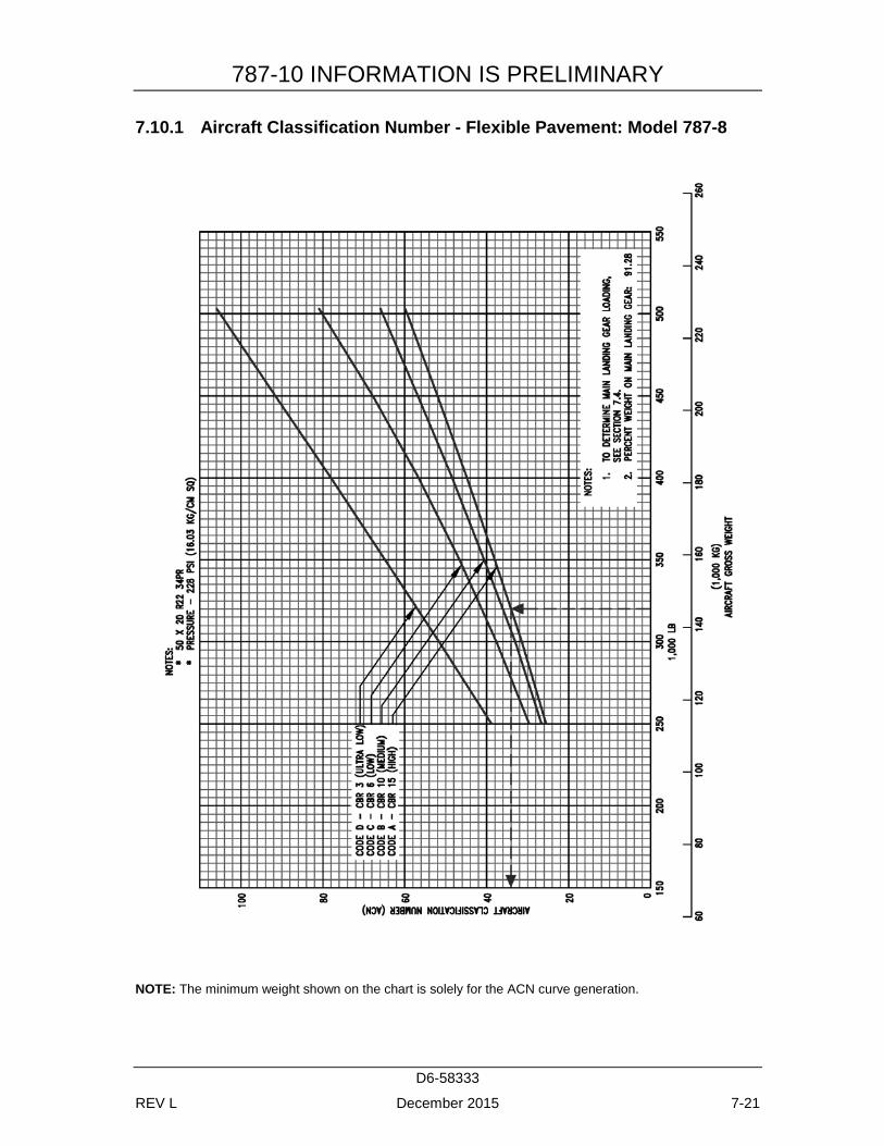
787-10 INFORMATION IS PRELIMINARY
D6-58333
REV L December 2015 7-21
7.10.1 Aircraft Classification Number - Flexible Pavement: Model 787-8
NOTE: The minimum weight shown on the chart is solely for the ACN curve generation.
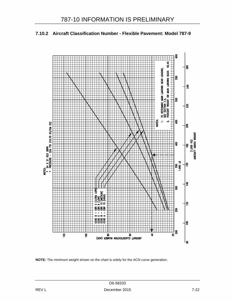
787-10 INFORMATION IS PRELIMINARY
D6-58333
REV L December 2015 7-22
7.10.2 Aircraft Classification Number - Flexible Pavement: Model 787-9
NOTE: The minimum weight shown on the chart is solely for the ACN curve generation.
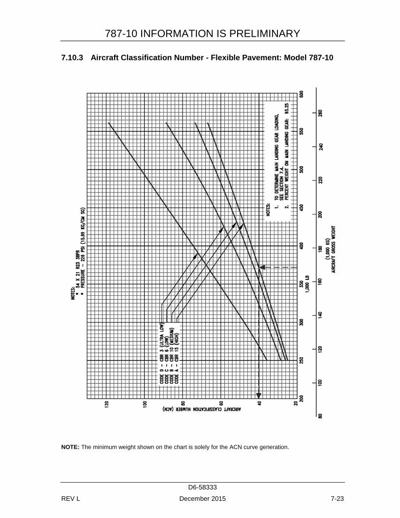
787-10 INFORMATION IS PRELIMINARY
D6-58333
REV L December 2015 7-23
7.10.3 Aircraft Classification Number - Flexible Pavement: Model 787-10
NOTE: The minimum weight shown on the chart is solely for the ACN curve generation.
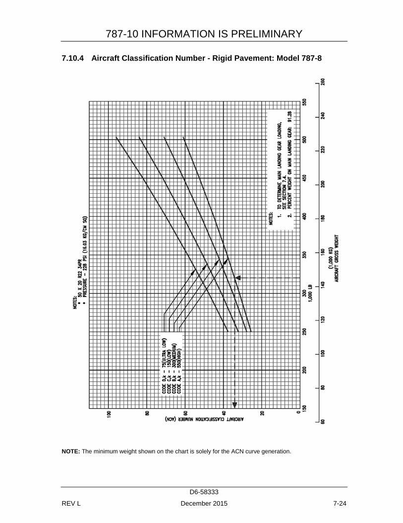
787-10 INFORMATION IS PRELIMINARY
D6-58333
REV L December 2015 7-24
7.10.4 Aircraft Classification Number - Rigid Pavement: Model 787-8
NOTE: The minimum weight shown on the chart is solely for the ACN curve generation.
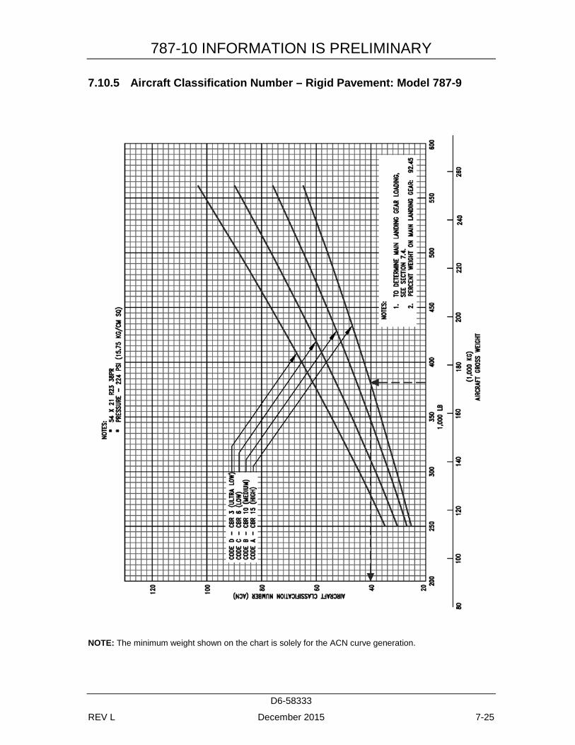
787-10 INFORMATION IS PRELIMINARY
D6-58333
REV L December 2015 7-25
7.10.5 Aircraft Classification Number – Rigid Pavement: Model 787-9
NOTE: The minimum weight shown on the chart is solely for the ACN curve generation.
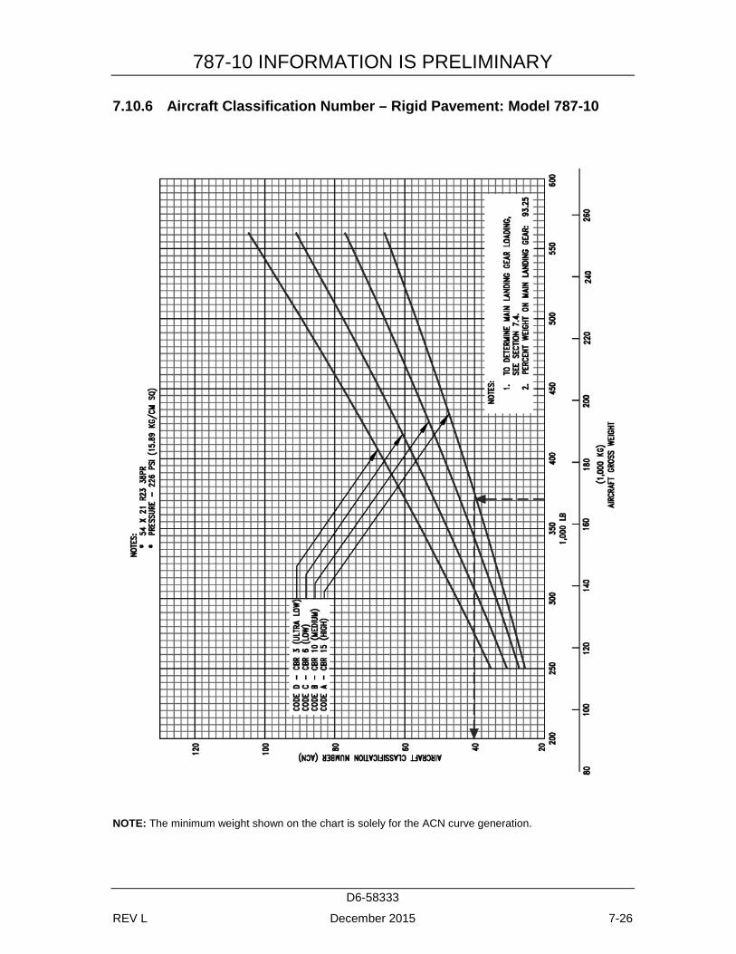
787-10 INFORMATION IS PRELIMINARY
D6-58333
REV L December 2015 7-26
7.10.6 Aircraft Classification Number – Rigid Pavement: Model 787-10
NOTE: The minimum weight shown on the chart is solely for the ACN curve generation.
787-10 INFORMATION IS PRELIMINARY
D6-58333
REV L December 2015 8-1
8.0 FUTURE 787 DERIVATIVE AIRPLANES
Boeing's philosophy is to evaluate the derivative potential of its airplanes to provide capabilities that maximize value to our customers.
Decisions to design and manufacture future derivatives of an airplane depend on many considerations, including customer requirements. Along with many other parameters, airport facilities are considered during the development of any future airplane.
787-10 INFORMATION IS PRELIMINARY
D6-58333
REV L December 2015 9-2
9.0 SCALED 787 DRAWINGS
The drawings in the following pages show airplane plan view drawings, drawn to approximate scale as noted. The drawings may not come out to exact scale when printed or copied from this document. Printing scale should be adjusted when attempting to reproduce these drawings. Three-view drawing files of the 787, along with other Boeing airplane models, can be downloaded from the following website:
http://www.boeing.com/airports
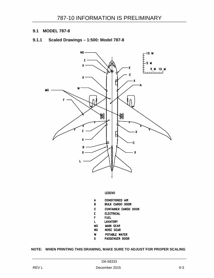
787-10 INFORMATION IS PRELIMINARY
D6-58333
REV L December 2015 9-3
9.1 MODEL 787-8
9.1.1 Scaled Drawings – 1:500: Model 787-8
NOTE: WHEN PRINTING THIS DRAWING, MAKE SURE TO ADJUST FOR PROPER SCALING
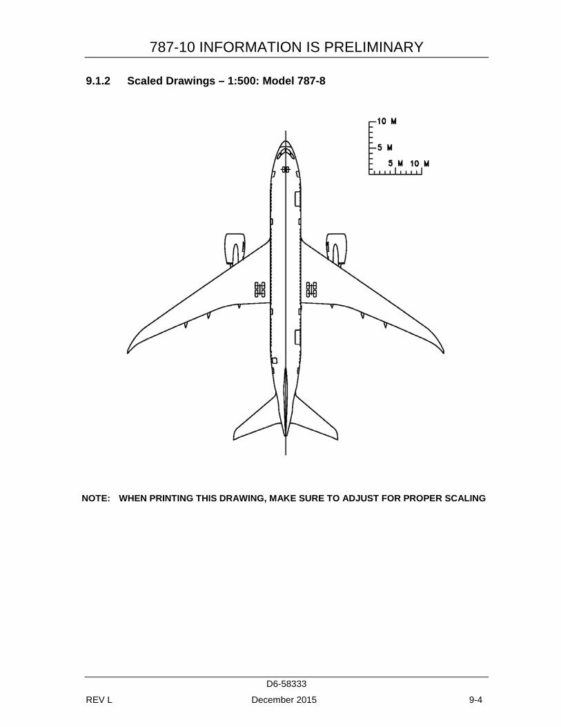
787-10 INFORMATION IS PRELIMINARY
D6-58333
REV L December 2015 9-4
9.1.2 Scaled Drawings – 1:500: Model 787-8
NOTE: WHEN PRINTING THIS DRAWING, MAKE SURE TO ADJUST FOR PROPER SCALING
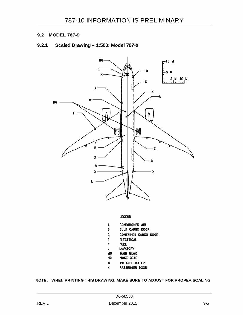
787-10 INFORMATION IS PRELIMINARY
D6-58333
REV L December 2015 9-5
9.2 MODEL 787-9
9.2.1 Scaled Drawing – 1:500: Model 787-9
NOTE: WHEN PRINTING THIS DRAWING, MAKE SURE TO ADJUST FOR PROPER SCALING
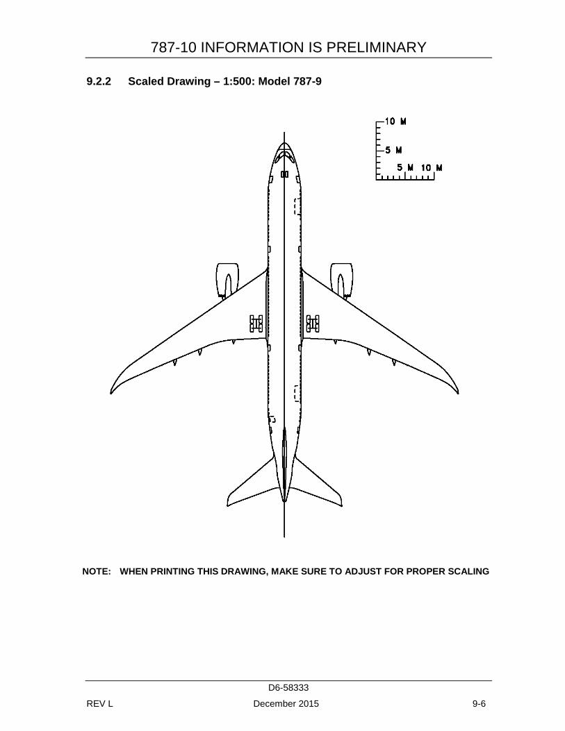
787-10 INFORMATION IS PRELIMINARY
D6-58333
REV L December 2015 9-6
9.2.2 Scaled Drawing – 1:500: Model 787-9
NOTE: WHEN PRINTING THIS DRAWING, MAKE SURE TO ADJUST FOR PROPER SCALING
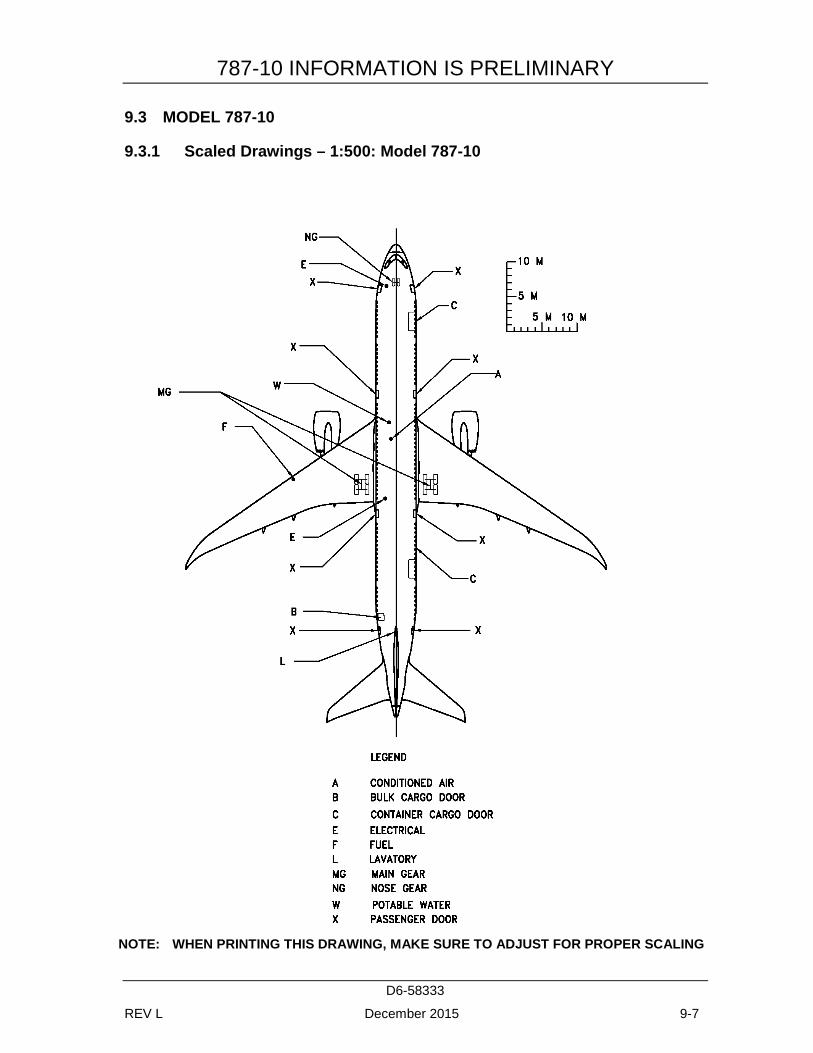
787-10 INFORMATION IS PRELIMINARY
D6-58333
REV L December 2015 9-7
9.3 MODEL 787-10
9.3.1 Scaled Drawings – 1:500: Model 787-10
NOTE: WHEN PRINTING THIS DRAWING, MAKE SURE TO ADJUST FOR PROPER SCALING
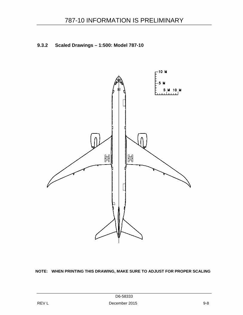
787-10 INFORMATION IS PRELIMINARY
D6-58333
REV L December 2015 9-8
9.3.2 Scaled Drawings – 1:500: Model 787-10
NOTE: WHEN PRINTING THIS DRAWING, MAKE SURE TO ADJUST FOR PROPER SCALING