78400/18400 Series es - Valve & Instrumentation Experts ...
36
Specification Data CP78400 10/10 78400/18400 Series LincolnLog ® High Pressure Anti-Cavitation Control Valves Putting You In Control es
Transcript of 78400/18400 Series es - Valve & Instrumentation Experts ...

Specification DataCP78400
10/10
78400/18400 Series
LincolnLog® High Pressure
Anti-Cavitation Control Valves
Putting You In Control
es

2 | Dresser Masoneilan
Dresser Masoneilan78400/18400 Series
LincolnLog® High PressureAnti-Cavitation Control Valves
2 | Dresser Masoneilan

CP78400/18400 Series LincolnLog® Control Valves | 3
Table of Contents
The Masoneilan LincolnLog is the premier high-pressure liquid letdown
valve in the process control industry. It is a field proven severe service
solution for cavitating and erosive applications in various industries. The
LincolnLog is uniquely designed to operate reliably in harsh environments
and dirty liquids. Key design features of the LincolnLog include:
Cavitation Elimination The multi-step flow path created by the LincolnLog trim design, reduces
the pressure drop in multiple stages without allowing the local pressure
to drop below the fluid vapor pressure thus preventing cavitation. These
active stages throttle in unison to avoid taking the full pressure drop
across any individual stage.
Dirt TolerantWide flow paths in the LincolnLog allow free passage of large particles
through the unique trim and body design without causing any damage or
loss of capacity. This ensures continuous and efficient operation by
eliminating concerns of potential clogging due to entrained particles.
The LincolnLog is a proven problem solver in dirty service applications.
Heavy Plug GuidingGuiding is provided along the full length of the plug by a hardened liner,
which minimizes any vibration effects and results in excellent dynamic
stability. This helps to improve product yield through accurate and
smooth process control.
Versatile Trim OptionsStandard LincolnLog trim is available in 3, 4 and 6 stages with different
staging ratios to cover the vast majority of high-pressure liquid letdown
services. Masoneilan can also provide engineered solutions consisting
of additional stages to satisfy specific application requirements. The
LincolnLog is available with both balanced and unbalanced plug designs
for greater application flexibility.
Protected Seat DesignOverlap is designed into the trim at low lift to keep high velocity flow
away from the valve seat. This helps to avoid seat erosion and extends
the operating life under high pressure drop conditions.
Reliable Tight ShutoffStandard seat leakage rating for the LincolnLog meets IEC 534-4 and
ANSI/FCI 70.2 Class V shutoff. An optional soft seat design provides Class
VI bubble tight shutoff. It includes a patented sliding metal collar design,
which protects the soft seat from extruding and serves as a back-up
seating surface. The LincolnLog can also be supplied with block valve
tight shutoff per MSS-SP-61.
Ease of MaintenanceLincolnLog’s simple top-entry design includes quick change trim for easy
access and removal. The integral liner and seat ring also reduces the
number of components and simplifies assembly and disassembly.
NACE and PED ComplianceThe LincolnLog is available for Sour Service Applications using the design
and construction methods defined in NACE Standard MR0103. Product
configurations for applications requiring compliance to MR0175 - 2003
or ISO 15156 are also available upon request. The LincolnLog is also
designed for compliance with Pressure Equipment Directives (PED)
requirements.
Features
Features ......................................................................................................3
General Data ...............................................................................................4
Numbering System .....................................................................................5
Temperature Range / Seat Leakage ...........................................................5
Balance Seal Pressure and Temperature Limits ........................................6
Ratings / Connections ................................................................................7
Flow Capacity and FL ..................................................................................7
Flow Characteristics ...................................................................................8
Trim Seat Protection ...................................................................................8
Valve Sizing Guidelines ..............................................................................9
Staging Ratios and Pressure Drop Guidelines ............................................9
Materials of Construction .........................................................................10
Soft Seat Design .......................................................................................21
Dimensions ...............................................................................................22
Weights .....................................................................................................28
Accessories and Options ..........................................................................33
Sales Offices ...............................................................................Back Cover

4 | Dresser Masoneilan
Optional designs are also available, such as larger
sizes, higher pressure ratings, special materials, or
additional trim stages as required. Consult factory for
design details and specifications.
� Flow Direction
Standard: Flow-to-open
� Body
Type: cast or forged globe style
cast or forged angle style
Sizes: 1" to 8" (DN 25 to DN 200)
Ratings: ANSI Class 600 to 2500
(ISO PN 100 to 420)
API 5000 to 10000
End connections: RFF, RTJ, socket weld,
butt weld, threaded
print flanges (forgings)
� Bonnet
Type: Bolted
Standard
Extension
� Body and Bonnet
Materials: carbon steel
316 stainless steel
chrome-moly
others
� Trim
Plug type: multi-step axial flow
(3, 4 and 6 stages)
Seat type: quick change
integral with plug liner (1" & 1.5" sizes)
metal seat
soft seat
Guide: heavy top guided (liner)
CV ratio: see Flow Capacity tables (page 7)
Flow characteristics: Modified linear (see page 8)
� Actuator
Type: Spring-diaphragm
Spring-return cylinder
Double-acting cylinder
Handwheel: Optional
General Data

CP78400/18400 Series LincolnLog® Control Valves | 5
No. ofStages*
Optional Configuration
Numbering System
1st 2nd 5th4th3rd
42nd
81st 6th
Temperature Range / Seat Leakage
* Additional stages are available to meet specific
operating conditions. Please consult Masoneilan.
Actuator Type
4 Axial Flow High Resistance (Downseating)
Trim TypeBody Series
1 Globe
7 Angle
F Forged
Body Design
EB Extension
Bonnet
0 Optional Trim
1 Trim A, Balanced Hard Seat
2 Trim B, Balanced Hard Seat
3 Trim C, Balanced Hard Seat
4 Trim A, Balanced Soft Seat
5 Trim B, Balanced Soft Seat
6 Trim C, Balanced Soft Seat
7 Trim A, Unbalanced Hard Seat
8 Trim B, Unbalanced Hard Seat
9 Trim C, Unbalanced Hard Seat
Trim Size
3 Three4 Four6 Six
20 Top Mounted Manual Handwheel
87 Spring-Diaphragm
Air to Close
88 Spring-Diaphragm Air to Open
84 Cylinder: Spring Return, Direct, Air to Close, Single or Double Acting (Fail Open Action
85 Cylinder: Spring Return, Reverse Air to Open, Single or Double Acting (Fail to Close)
86 Cylinder: Double Acting, Without Springs, Air to Open or Air to Close Action
Trim Type Seat TypeTemperature Range (1) Seat
Leakage
Class (2)
Valve Sizes
inches DN min. max.(4)
1 25 Unbalanced Metal Seat -20°F (-29°C) 600°F (316°C)
V
(See Note 3)1.5 to 8 40 to 200Balanced Metal Seat -20°F (-29°C) 600°F (316°C)
Unbalanced Metal Seat -20°F (-29°C) 600°F (316°C)
2 to 8 50 to 200Balanced or
UnbalancedSoft Seat -20°F (-29°C) 450°F (232°C) VI
1. Designs for higher or lower temperatures are available. Please consult Masoneilan.
2. Seat leakage class ratings per IEC 534-4 and ANSI/FCI 70.2. Class V seat leakage is standard and Class VI is optional.
3. Optional block valve tight shutoff per MSS-SP-61 also available.
4. Max. temp. limit of 600°F (316°C) with unbalanced trim requires use of optional flexible graphite packing or an extension bonnet.

6 | Dresser Masoneilan
Balance Seal Pressure and
Temperature Limits
Pres
sure
in p
si (b
ar)
Temperature Range in °F (°C)
7000 (483)
6000 (414)
5000 (345)
4000 (276)
3000 (207)
2000 (138)
1000 (69)
0
200°F(93°C)
300°F(149°C)
400°F(204°C)
500°F(260°C)
600°F(316°C)
700°F(371°C)
PTFE (Fluoroloy® A21)with Elgiloy® Spring and
PTFE Back-up Rings
LincolnLog 78400/18400 Balance Seal Pressure-Temperature Application Range

CP78400/18400 Series LincolnLog® Control Valves | 7
Ratings/Connections
Flow Capacity and FL
Standard Capacity – 3-Stage Design Flow Characteristic: MODIFIED LINEAR
Orifice Diameter
1 25 .70 17.8 .25 6.35 2.0 .98 .05
1.5 40 1.00 25.4 .25 6.35 3.8 .98 .10
2 50 1.50 38.1 .38 9.65 9.0 .98 .15
3 80 2.25 57.2 .62 15.7 20 .98 .25
4 100 2.88 73.2 .75 19.1 34 .98 .43
6 150 4.12 105 1.00 25.4 65 .98 .56
8 200 5.38 137 1.25 31.8 135 .98 1.0
Valve Size
Flow Characteristic: MODIFIED LINEAR
Travel Trim A Trim B Trim C Min.Cont.
CV inches DN inches mm inches mm C
V F
L C
V F
L C
V F
L
1 25 .70 17.8 .25 6.35 1.0 .996 1.4 .994 1.7 .991 .04
1.5 40 1.00 25.4 .25 6.35 1.9 .996 2.5 .994 3.2 .991 .08
2 50 1.50 38.1 .38 9.65 4.5 .996 6.0 .994 7.5 .991 .12
3 80 2.25 57.2 .62 15.7 10 .996 13 .994 16.5 .991 .20
4 100 2.88 73.2 .75 19.1 16.5 .996 22 .994 28 .991 .35
6 150 4.12 105 1.00 25.4 34 .996 45 .994 56 .991 .46
8 200 5.38 137 1.25 31.8 70 .996 90 .994 115 .991 .80
Valve Size Orifice Diameter
Flow Characteristic: MODIFIED LINEARStandard Capacity – 6-Stage Design
Travel Trim A Trim B Trim C Min. Cont.
CV inches DN inches mm inches mm C
V F
L C
V F
L C
V F
L
1 25 .70 17.8 .25 6.35 .80 .998 1.0 .997 1.4 .994 .03
1.5 40 1.00 25.4 .25 6.35 1.4 .998 1.8 .997 2.5 .994 .05
2 50 1.50 38.1 .38 9.65 3.5 .998 4.5 .997 6.0 .994 .08
3 80 2.25 57.2 .62 15.7 7.5 .998 9.5 .997 13 .994 .13
4 100 2.88 73.2 .75 19.1 12 .998 16 .997 22 .994 .22
6 150 4.12 105 1.00 25.4 25 .998 33 .997 45 .994 .30
8 200 5.38 137 1.25 31.8 50 .998 65 .997 91 .994 .65
Valve Size Orifice Diameter
� RF Flanged � Socket Weld �Threaded � RT Joint � Butt Weld
Pressure Class (2)
DN 600 900 1500 2500
1 & 1.5 25 & 40 ��� � � ��� � � ��� � � ��� � �
2 50 ��� � � ��� � � ��� � � ��� � �
3 80 � � � � � � � � � � � �
4 100 � � � � � � � � � � � �
6 150 � � � � � � � � � � � �
8 200 � � � � � � � � � � � �
inches
Valve Size (1)
1) Sizes, ratings and end connections are available in both globe and angle body styles.
2) Pressure classes shown represent ASME/ANSI ratings and equivalent PN ratings.
Standard Capacity – 4-Stage Design
inches DN inches mm inches mm
Travel
FL
Trim C Min. Cont.
CVC
V

8 | Dresser Masoneilan8 | Dresser Masoneilan
The LincolnLog trim provides a smooth modified linear control
characteristic with “clearance flow” capacity over the initial 15% of
valve travel as shown in the generic chart and table at right.
Incorporation of the multi-stage “clearance flow” design concept
prevents high pressure drops across the LincolnLog seating area while
throttling at low lifts. This feature helps to extend trim life significantly,
resulting in dependable and tight shutoff whenever required. It also
improves the throttling control stability and performance at low lifts,
while providing smooth, accurate and continuous capacity control from
15% to 100% plug travel. Controllability extends from the Maximum
Rated CV to the Minimum Controllable CV for any valve size resulting in
typical turndown ratios of 50:1.
15 - 100% of Plug TravelThere is much greater flow area through the valve seat versus the plug notches. As a result, pressure drop and velocities across the critical seating surfaces are controlled eliminating seat damage.
LincolnLog Trim Overlap Seat Protection Feature
0 - 15% of Plug TravelTrim overlap with the valve in the closed or low lift positions.
LincolnLog CV vs. Travel
Flow DirectionFlow Direction
Flow Characteristics
Trim Seat Protection
* Clearance Flow Only
40 50 60 70 80 90 100
% Max. CV * * 3 15 27 39 52 64 76 88 100
% Max. Opening 5 10 20 30
The “clearance flow” feature described in the previous section is achieved through the trim overlap design
illustrated below:

CP78400/18400 Series LincolnLog® Control Valves | 9
Valve Sizing Guidelines
General
LincolnLog multi-stage control valves can be sized using either
standard IEC/ISA equations or using the latest Masoneilan sizing
and selection software program.
Noise Predictions
Valve noise calculations can be performed using the Masoneilan
sizing and selection program based on the latest IEC equations.
The serial stage construction of the LincolnLog design helps to
significantly reduce trim noise. Calculating the noise at the last
stage of the LincolnLog trim will closely approximate the overall
valve noise produced. Pressure drop across the last stage can be
derived from the table below and used in the noise calculations.
Trim Selection
As indicated in the table below, the LincolnLog is available in various
standard trim types and number of stages. Each trim style provides
different staging ratios and different pressure drop percentages per
stage. Recommended limits for ΔP per stage are 800 psi (60 bar) for
continuous duty cycle applications and up to 1000 psi (70 bar) ΔP per
stage for intermittent service. The recommended operating throttling ΔP
limits are also shown in the table below.
Engineered Solutions
For flashing service, the expansion ratio of the fluid will determine the
appropriate staging ratio to apply. Non-standard staging ratios can be
supplied for compressible two-phase flow or flashing conditions not
covered by the standard trim. Please consult Masoneilan for proper
sizing and design of engineered solutions for these types of applications.
No. of
Stages
Pressure Drop
per Stage (3)
Maximum Recommended Throttling ΔP
Continuous Service Intermittent Service
StagesFraction of
Total ΔPpsi bar psi bar
C 3 1-1-21 to 2 .44
1595 110 2030 1403 .11
C 4 1-1-1-21 to 3 .31
2248 155 2900 2004 .08
B 4 1-1-2-3
1 to 2 .42
1885 130 2320 1603 .11
4 .05
A 4 1-1-2-4
1 to 2 .43
1885 130 2320 1603 .11
4 .03
C 6 1-1-1-1-1-21 to 5 .19
3698 255 4713 3256 .05
B 6 1-1-1-1-2-3
1 to 4 .23
3480 240 4350 3005 .06
6 .025
A 6 1-1-1-1-2-4
1 to 4 .23
3408 235 4278 2955 .06
6 .014
Trim TypeStageing
Ratios (1)(2)
Staging Ratios & Pressure
Drop Guidelines
(1) Staging ratios provide approximations of the relative area ratios for each specific trim type. As an example, a staging ratio of 1-1-2
indicates that the final stage for that trim type has approximately twice the area of the first two stages.
(2) Staging ratios do not have any relative correlation between the different trim types.
(3) Recommended limits for ΔP per stage are 800 psi (60 bar) for continuous duty cycle applications and up to 1000 psi (70 bar) ΔP
per
stage for intermittent service.

10 | Dresser Masoneilan
Materials of Construction
1" Size Unbalanced Assembly
1
2
5
25
4
3
6
7
10
11
22
23
21
20
18

CP78400/18400 Series LincolnLog® Control Valves | 11
Materials of Construction
1.5" Size Balanced Assembly
Correct Seal Ring Installationshowing lower back-up ring 90° angle
facing the extrusion gap
1
2
5
3
4
6
7
8
9
10
11
18
20
21
22
23
25
20
9
8
10
18
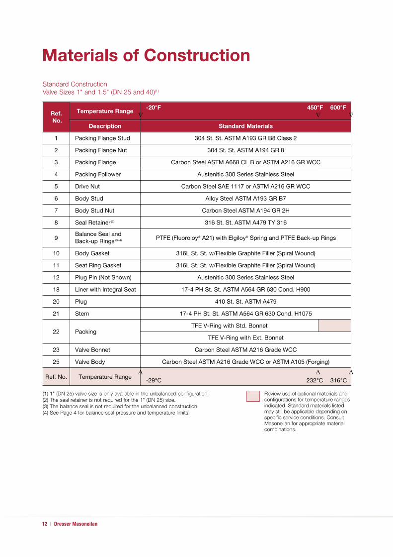
12 | Dresser Masoneilan
Materials of Construction
Ref.
No.
Temperature Range-20°F 450°F 600°F
Description Standard Materials
1 Packing Flange Stud 304 St. St. ASTM A193 GR B8 Class 2
2 Packing Flange Nut 304 St. St. ASTM A194 GR 8
3 Packing Flange Carbon Steel ASTM A668 CL B or ASTM A216 GR WCC
4 Packing Follower Austenitic 300 Series Stainless Steel
5 Drive Nut Carbon Steel SAE 1117 or ASTM A216 GR WCC
6 Body Stud Alloy Steel ASTM A193 GR B7
7 Body Stud Nut Carbon Steel ASTM A194 GR 2H
8 Seal Retainer (2) 316 St. St. ASTM A479 TY 316
9Balance Seal and Back-up Rings (3)(4) PTFE (Fluoroloy® A21) with Elgiloy® Spring and PTFE Back-up Rings
(1) 1" (DN 25) valve size is only available in the unbalanced configuration.
(2) The seal retainer is not required for the 1" (DN 25) size.
(3) The balance seal is not required for the unbalanced construction.
(4) See Page 4 for balance seal pressure and temperature limits.
Review use of optional materials and
configurations for temperature ranges
indicated. Standard materials listed
may still be applicable depending on
specific service conditions. Consult
Masoneilan for appropriate material
combinations.
Standard Construction
Valve Sizes 1" and 1.5" (DN 25 and 40)(1)
� � �
10 Body Gasket 316L St. St. w/Flexible Graphite Filler (Spiral Wound)
11 Seat Ring Gasket 316L St. St. w/Flexible Graphite Filler (Spiral Wound)
12 Plug Pin (Not Shown) Austenitic 300 Series Stainless Steel
18 Liner with Integral Seat 17-4 PH St. St. ASTM A564 GR 630 Cond. H900
20 Plug 410 St. St. ASTM A479
21 Stem 17-4 PH St. St. ASTM A564 GR 630 Cond. H1075
22 PackingTFE V-Ring with Std. Bonnet
TFE V-Ring with Ext. Bonnet
23 Valve Bonnet Carbon Steel ASTM A216 Grade WCC
25 Valve Body Carbon Steel ASTM A216 Grade WCC or ASTM A105 (Forging)
Ref. No. Temperature Range-29°C 232°C 316°C
� � �

CP78400/18400 Series LincolnLog® Control Valves | 13
(1) Standard materials and processes are in accordance with the
requirements of NACE specification MR0103. Applications requiring
compliance to MR0175 - 2003 or ISO 15156 would need to be
reviewed by Masoneilan.
(2) 1" (DN 25) valve size is only available in the unbalanced configuration.
(3) The seal retainer is not required for the 1" (DN 25) size.
(4) The balance seal is not required for the unbalanced construction.
(5) See Page 4 for balance seal pressure and temperature limits.
Review use of optional materials and
configurations for temperature ranges
indicated. Standard materials listed may
still be applicable depending on specific
service conditions. Consult Masoneilan
for appropriate material combinations.
Materials of Construction
Ref.
No.
Temperature Range-20°F 450°F 600°F
Description Standard Materials
1 Packing Flange Stud 304 St. St. ASTM A193 GR B8 Class 2
2 Packing Flange Nut 304 St. St. ASTM A194 GR 8
3 Packing Flange Carbon Steel ASTM A668 CL B or ASTM A216 GR WCC
4 Packing Follower Austenitic 300 Series Stainless Steel
5 Drive Nut Carbon Steel SAE 1117 or ASTM A216 GR WCC
6 Body Stud Alloy Steel ASTM A193 GR B7
7 Body Stud Nut Carbon Steel ASTM A194 GR 2H
8 Seal Retainer (3) 316 St. St. ASTM A479 TY 316
9Balance Seal and Back-up Rings (4)(5) PTFE (Fluoroloy® A21) with Elgiloy® Spring and PTFE Back-up Rings
Standard NACE (1) Construction
Valve Sizes 1" and 1.5" (DN 25 and 40)(2)
� � �
10 Body Gasket 316L St. St. w/Flexible Graphite Filler (Spiral Wound)
11 Seat Ring Gasket 316L St. St. w/Flexible Graphite Filler (Spiral Wound)
12 Plug Pin (Not Shown) Austenitic 300 Series Stainless Steel
18 Liner with Integral Seat Nitronic 50 ASTM A479 TY XM-19
20 Plug 17-4 PH St. St. ASTM A564 GR 630 Cond. H1150M
21 Stem Nitronic 50 ASTM A479 TY XM-19
22 PackingTFE V-Ring with Std. Bonnet
TFE V-Ring with Ext. Bonnet
23 Valve Bonnet Carbon Steel ASTM A216 Grade WCC
25 Valve Body Carbon Steel ASTM A216 Grade WCC or ASTM A105 (Forging)
Ref. No. Temperature Range-29°C 232°C 316°C
� � �

14 | Dresser Masoneilan
2" Size Balanced Assembly
2" Size Unbalanced Trim Detail
Soft Seat Option
Correct Seal Ring Installationshowing lower back-up ring 90° angle
facing the extrusion gap
Materials of Construction
20
9
8
10
18
1
2
3
4
6
7
8
9
10
11
18
20
21
22
23
25
11
19
5

CP78400/18400 Series LincolnLog® Control Valves | 15
3" to 8" Size Balanced Assembly
Soft Seat Option
Correct Seal Ring Installationshowing lower back-up ring 90° angle
facing the extrusion gap
Bonnet Seating Angle Detail
3" to 8" Size Unbalanced Trim Detail
20
9
8
10
18
3
4
6
7
8
9
10
20
21
22
23
24
11
18
11
19
11
25
1
2
5
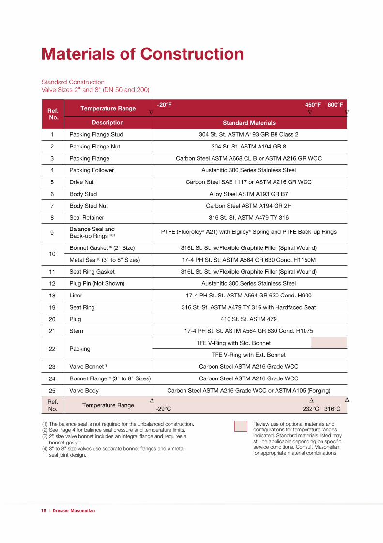
16 | Dresser Masoneilan
Materials of Construction
(1) The balance seal is not required for the unbalanced construction.
(2) See Page 4 for balance seal pressure and temperature limits.
(3) 2" size valve bonnet includes an integral flange and requires a
bonnet gasket.
(4) 3" to 8" size valves use separate bonnet flanges and a metal
seal joint design.
Review use of optional materials and
configurations for temperature ranges
indicated. Standard materials listed may
still be applicable depending on specific
service conditions. Consult Masoneilan
for appropriate material combinations.
316L St. St. w/Flexible Graphite Filler (Spiral Wound)
Ref.
No.
Temperature Range-20°F 450°F 600°F
Standard Materials
Standard Construction
Valve Sizes 2" and 8" (DN 50 and 200)
� � �����
Description
Packing Flange Stud 304 St. St. ASTM A193 GR B8 Class 2
Packing Flange Nut 304 St. St. ASTM A194 GR 8
Packing Flange Carbon Steel ASTM A668 CL B or ASTM A216 GR WCC
Packing Follower Austenitic 300 Series Stainless Steel
Drive Nut Carbon Steel SAE 1117 or ASTM A216 GR WCC
Body Stud Alloy Steel ASTM A193 GR B7
Body Stud Nut Carbon Steel ASTM A194 GR 2H
Seal Retainer 316 St. St. ASTM A479 TY 316
Bonnet Gasket (3) (2" Size)
Metal Seal(4) (3" to 8" Sizes) 17-4 PH St. St. ASTM A564 GR 630 Cond. H1150M
Seat Ring Gasket 316L St. St. w/Flexible Graphite Filler (Spiral Wound)
Plug Pin (Not Shown) Austenitic 300 Series Stainless Steel
Liner 17-4 PH St. St. ASTM A564 GR 630 Cond. H900
Seat Ring 316 St. St. ASTM A479 TY 316 with Hardfaced Seat
Plug 410 St. St. ASTM 479
Stem 17-4 PH St. St. ASTM A564 GR 630 Cond. H1075
PackingTFE V-Ring with Std. Bonnet
TFE V-Ring with Ext. Bonnet
Valve Bonnet (3) Carbon Steel ASTM A216 Grade WCC
Bonnet Flange(4) (3" to 8" Sizes) Carbon Steel ASTM A216 Grade WCC
Valve Body Carbon Steel ASTM A216 Grade WCC or ASTM A105 (Forging)
Temperature Range-29°C 232°C 316°C
� � �1
2
3
4
5
6
7
8
10
11
12
18
19
20
21
22
23
24
25
Ref. No.
9Balance Seal and Back-up Rings (1)(2)
PTFE (Fluoroloy® A21) with Elgiloy® Spring and PTFE Back-up Rings

CP78400/18400 Series LincolnLog® Control Valves | 17
(1) Standard materials and processes are in accordance with the requirements
of NACE specification MR0103. Applications requiring compliance to
MR0175 - 2003 or ISO 15156 would need to be reviewed by Masoneilan.
(2) The balance seal is not required for the unbalanced construction.
(3) See Page 4 for balance seal pressure and temperature limits.
(4) 2" size valve bonnet includes an integral flange and requires a
bonnet gasket.
(5) 3" to 8" size valves use separate bonnet flanges and a metal
seal joint design.
Review use of optional materials and
configurations for temperature ranges
indicated. Standard materials listed may
still be applicable depending on specific
service conditions. Consult Masoneilan
for appropriate material combinations.
Materials of Construction
316L St. St. w/Flexible Graphite Filler (Spiral Wound)
Ref.
No.
Temperature Range-20°F 450°F 600°F
Standard Materials
Standard NACE (1) Construction
Valve Sizes 2" and 8" (DN 50 and 200)
� � �����
Description
Packing Flange Stud 304 St. St. ASTM A193 GR B8 Class 2
Packing Flange Nut 304 St. St. ASTM A194 GR 8
Packing Flange Carbon Steel ASTM A668 CL B or ASTM A216 GR WCC
Packing Follower Austenitic 300 Series Stainless Steel
Drive Nut Carbon Steel SAE 1117 or ASTM A216 GR WCC
Body Stud Alloy Steel ASTM A193 GR B7
Body Stud Nut Carbon Steel ASTM A194 GR 2H
Seal Retainer 316 St. St. ASTM A479 TY 316
Bonnet Gasket (4) (2" Size)
Metal Seal(5) (3" to 8" Sizes) 17-4 PH St. St. ASTM A564 GR 630 Cond. H1150M
Seat Ring Gasket 316L St. St. w/Flexible Graphite Filler (Spiral Wound)
Plug Pin (Not Shown) Austenitic 300 Series Stainless Steel
Liner Nitronic 50 ASTM A479 TY XM-19
Seat Ring 316 St. St. ASTM A479 TY 316 with Hardfaced Seat
Plug 17-4 PH St. St. ASTM A564 GR 630 Cond. H1150M
Stem Nitronic 50 ASTM A479 TY XM-19
PackingTFE V-Ring with Std. Bonnet
TFE V-Ring with Ext. Bonnet
Valve Bonnet (4) Carbon Steel ASTM A216 Grade WCC
Bonnet Flange(5) (3" to 8" Sizes) Carbon Steel ASTM A216 Grade WCC
Valve Body Carbon Steel ASTM A216 Grade WCC or ASTM A105 (Forging)
Temperature Range -29°C 232°C 316°C
� � �1
2
3
4
5
6
7
8
10
11
12
18
19
20
21
22
23
24
25
Ref. No.
9Balance Seal and Back-up Rings (2)(3)
PTFE (Fluoroloy® A21) with Elgiloy® Spring and PTFE Back-up Rings

18 | Dresser Masoneilan
Materials of Construction
3" to 8" Size Unbalanced Trim Detail
Cryogenic Service Configuration
Materials of Construction
1
2
5
4
3
6
7
10
11
25
11
19
18
24
20
23
22
21

CP78400/18400 Series LincolnLog® Control Valves | 19
Materials of Construction
Cryogenic Service Configuration
18400/78400 Series Anti-Cavitation Control Valve
Valve Sizes 1" to 1.5" (DN 25 and 40)
Ref. No. Description Standard Materials
1 Packing Flange Stud 304 Stainless Steel ASTM A193 Gr B8 Class 22 Packing Flange Nut 304 Stainless Steel ASTM A194 Gr 83 Packing Flange Austenitic 300 Series Stainless Steel4 Packing Follower Austenitic 300 Series Stainless Steel5 Drive Nut Carbon Steel SAE 1117 or ASTM A216 Gr WCC with ENP6 Valve Body Stud 304 Stainless Steel ASTM A193 Gr B8 Class 27 Valve Body Nut 304 Stainless Steel ASTM A194 Gr 810 Body Gasket 316L St. St. w/ Flexible Graphite Filler (Spiral Wound)11 Seat Ring Gasket 316L St. St. w/ Flexible Graphite Filler (Spiral Wound)12 Plug Pin (Not Shown) Austenitic 300 Series Stainless Steel
18 Liner with Integral Seat 316 Stainless Steel ASTM A479 TY 316 with Chrome-Plate and Hardfaced Seat
20 Plug316 Stainless Steel ASTM A479 TY 316 with Hardfacing
Nitronic 50 with Hardfaced Seat
21 Plug Stem316 Stainless Steel ASTM A479 TY 316
Inconel X-750 ASTM B637 Gr 68822 Packing Teflon V-Ring23 Valve Bonnet 316 Stainless Steel ASTM A351 Gr CF8M25 Valve Body 316 Stainless Steel ASTM A351 Gr CF8M
Valve Sizes 2" to 8" (DN 50 and 400)
Ref. No. Description Standard Materials
1 Packing Flange Stud 304 Stainless Steel ASTM A193 Gr B8 Class 22 Packing Flange Nut 304 Stainless Steel ASTM A194 Gr 83 Packing Flange Austenitic 300 Series Stainless Steel4 Packing Follower Austenitic 300 Series Stainless Steel5 Drive Nut Carbon Steel SAE 1117 or ASTM A216 Gr WCC with ENP6 Valve Body Stud 304 Stainless Steel ASTM A193 Gr B8 Class 27 Valve Body Nut 304 Stainless Steel ASTM A194 Gr 8
10Bonnet Gasket (2" Size) 316L St. St. w/ Flexible Graphite Filler (Spiral Wound)Metal Seal (3" to 8" Sizes) A286 Super Alloy ASTM A638 Gr 660
11 Seat Ring Gasket 316L St. St. w/ Flexible Graphite Filler (Spiral Wound)12 Plug Pin (Not Shown) Austenitic 300 Series Stainless Steel18 Liner 316 Stainless Steel ASTM A479 TY 316 with Chrome-Plate 19 Seat Ring 316 Stainless Steel ASTM A479 TY 316 with Hardfaced Seat
20 Plug316 Stainless Steel ASTM A479 TY 316 with Hardfacing
Nitronic 50 with Hardfaced Seat
21 Plug Stem316 Stainless Steel ASTM A479 TY 316
Inconel X-750 ASTM B637 Gr 68822 Packing Teflon V-Ring23 Valve Bonnet 316 Stainless Steel ASTM A351 Gr CF8M24 Bonnet Flange (3" to 8" Sizes) 316 Stainless Steel ASTM A351 Gr CF8M25 Valve Body 316 Stainless Steel ASTM A351 Gr CF8M
(1) Materials focused for cryogenic LNG applications (-196°C).
Consult factory for suitability in other cryogenic applications.
(2) Consult factory for NACE applications.
(3) Trim offerings limited to unbalanced designs.
(4) Consult factory for proper actuator sizing to provide
correct valve shut-off.
(5) JIS and EN equivalents available.
Materials of Construction

20 | Dresser Masoneilan
Materials of Construction
Ref. No.Temperature Range(1)
-20°F 450°F 600°F
Description Optional Materials
19 Soft Seat S/A (2" to 8" Sizes) See Below
19A Seat RingStandard - 17-4 PH St. St. ASTM A564 GR 630 Cond. H1075
NACE - 17-4 PH St. St. ASTM A564 GR 630 Cond. H1150M
19B Soft Seat Insert Glass Reinforced PTFE (Fluorogold®)
19C Sliding CollarStandard - 17-4 PH St. St. ASTM A564 GR 630 Cond. H1075
NACE - 17-4 PH St. St. ASTM A564 GR 630 Cond. H1150M
20 Plug(2) 440B or 440C St. St. ASTM A276
22 Packing(3)
LE® Packing(4)
PTFE with Carbon Fiber
Flexible Graphite
23 Valve Bonnet(5)316 St. St. ASTM A351 GR CF8M
Chrome-Moly Steel ASTM A217 GR WC9
25 Valve Body(5)316 St. St. ASTM A351 GR CF8M or ASTM A182 GR F316 (Forging)
Chrome-Moly Steel ASTM A217 GR WC9 or ASTM A182 GR F22 (Forging)
Ref. No. Temperature Range-29°C 232°C 316°C
(1) Consult Masoneilan for material combinations for temperatures below –20°F (-29°C) or
above 600°F (316°C).
(2) Optional plug designs using hardened 440B or 440C requires stems with male threads
and plugs with female threads.
(3) Teflon-based packing can also be applied up to 600°F (316°C) with an extension bonnet.
(4) LE Packing for low emissions applications is limited to maximum operating pressure of
1500 psig (104 bar).
(5) Consult factory for trim material requirements for 316 St. St. body and bonnet assemblies
relative to application service conditions.
Review use of optional materials and
configurations for temperature ranges
indicated. Standard materials listed may
still be applicable depending on specific
service conditions. Consult Masoneilan for
appropriate material combinations.
Ref. No.Temperature Range -20°F 600°F
Description Optional Materials
18Liner(2) or Liner with Integral Seat
Ferralium® 255 ASTM A479 Duplex St. Steel
Ferralium® 255 ASTM A479 Duplex St. Steel
316 St. St. ASTM A479 TY316 with Boronizing
316 St. St. ASTM A479 TY316 with Boronizing
410 St. St. ASTM A479 TY410 with Boronizing
410 St. St. ASTM A479 TY410 with Boronizing
410 St. St. ASTM A479 TY410 with Boronizing
19 Seat Ring(3)
20 Plug(4)
Inconel 718 ASTM B637 GR 7178
316 St. St. ASTM A479 TY316 with Boronizing
21 Stem Nitronic 50 ASTM A479 TY XM-19
Ref. No. Temperature Range -29°C 316°C
�
���
�
��
�
��
Other Optional Materials (1)
78400/18400 Series Optional Materials
(1) Listed are typical optional materials for refining applications, including sour water letdown, cold high-pressure liquid letdown, and amine service.
(2) Material noted is recommended for the separate liner (2" to 8" sizes) or the liner with integral seat ring (1" and 1.5" sizes).
(3) The standard 316 St. St. hard-faced seat ring can be applied in most of the refining applications noted except for amine service. Ferralium 255
is recommended for the separate seat ring in amine service.
(4) Some material combinations may require electroless nickel or hard chrome plating to prevent galling. Consult factory for specific requirements.

CP78400/18400 Series LincolnLog® Control Valves | 21
Soft Seat Design
The LincolnLog is available with an optional soft seat design in valve sizes
2" to 8" (DN 50 to DN 200) providing bubble tight Class VI shutoff seat
leakage. This soft seat design includes a patented sliding metal collar
feature as shown below.
The metal collar holds the PTFE soft seat element in place and prevents it
from extruding out during operation. Fluid pressure acts to push the collar
up to protect the elastomer seat as the valve is throttling. As the valve plug
returns to the closed position, it moves the metal collar down to expose
the filled PTFE “Reservoir” creating the soft seat interface. Combined
with the LincolnLog trim overlap feature, the soft seat design will provide
long-term dependable tight shutoff with minimal maintenance. The filled
PTFE “Reservoir” will also compensate for any potential wear in the
seating surfaces.
19A
Soft Seat Option
19B
19C

22 | Dresser Masoneilan
Dimensions (inches)
Cast Globe Style Cast Angle Style
18400/78400 Series Cast Body Dimensions (inches)
ANSI Class 600 through 2500 and equivalent PN
Valve Size
(inches)
A
ANSI Class
600-900
ANSI Class
1500
ANSI Class
2500
ANSI Class
600
ANSI Class
900
ANSI Class
1500
ANSI Class
2500
SW
& THDBW
SW
& THD BW
SW
& THD RF RF RTJ RF RTJ RF RTJ
1 7.75 7.75 7.75 7.75 8.50 8.50 11.50 11.50 11.50 11.50 11.50 11.50 12.12 12.12
1.5 9.25 9.25 9.25 9.25 10.25 10.25 12.25 12.25 12.25 12.25 12.25 12.25 14.12 14.12
2 14.75 14.75 14.75 14.75 14.75 14.75 14.75 14.87 14.75 14.87 14.75 14.87 16.25 16.37
3 17.38 18.12 19.62 17.38 17.50 17.38 17.50 18.12 18.24 19.62 19.75
4 20.12 20.87 22.62 20.12 20.25 20.12 20.25 20.87 21.00 29.00 29.38
6 30.25 30.25 32.25 30.25 30.37 30.25 30.37 30.25 30.62 32.25 32.75
8 32.75 32.75 40.25 36.00 36.12 36.00 36.12 38.25 38.62 40.25 40.87
Valve Size
(inches)
B
ANSI Class
600-1500
ANSI Class
2500
ANSI Class
600
ANSI Class
900
ANSI Class
1500
ANSI Class
2500
BW SW & THD BW SW & THD RF & RTJ RF & RTJ RF & RTJ RF & RTJ
1 1.97 1.97 1.97 1.97 2.44 2.94 2.94 3.13
1.5 2.62 2.62 2.62 2.62 3.06 3.50 3.50 4.00
2 3.64 3.64 3.64 3.64 3.25 4.25 4.25 4.63
3 5.31 5.37 4.13 4.75 5.25 6.00
4 6.28 7.07 5.37 5.75 6.12 7.00
6 8.94 8.94 7.00 7.50 7.75 9.50
8 10.63 10.63 8.25 9.25 9.50 10.87
RTJBW

CP78400/18400 Series LincolnLog® Control Valves | 23
Dimensions (inches)
Cast Globe Style Cast Angle Style
18400/78400 Series Cast Body Dimensions (inches)
ANSI Class 600 through 2500 and equivalent PN
Valve
Size
(inches)
E
ANSI Class
600-900
ANSI Class
1500
ANSI Class
2500
ANSI Class
600
ANSI Class
900
ANSI Class
1500
ANSI Class
2500
BWSW
& THDBW
SW
& THD BWSW
& THD RF RTJ RF RTJ RF RTJ RF RTJ
1 3.87 3.87 3.87 3.87 4.25 4.25 5.75 5.75 5.75 5.75 5.75 5.75 6.06 6.06
1.5 4.63 4.63 4.63 4.63 5.13 5.13 6.13 6.13 6.13 6.13 6.13 6.13 7.06 7.12
2 7.38 7.38 7.38 7.38 7.38 7.38 7.38 7.44 7.38 7.44 7.38 7.44 8.13 8.19
3 8.69 9.06 9.81 8.69 8.75 8.69 8.75 9.06 9.12 9.81 9.87
4 10.06 10.44 11.31 10.06 10.13 10.06 10.13 10.44 10.50 14.50 14.68
6 15.13 15.13 16.13 15.13 15.19 15.13 15.19 15.13 15.31 16.13 16.37
8 16.37 16.37 20.13 18.00 18.06 18.00 18.06 19.13 19.31 20.13 20.44
Valve Size
(inches)
C D
Standard Bonnet Extension Bonnet Standard Bonnet Extension Bonnet
ANSI Class 600-2500 ANSI Class 600-2500 ANSI Class 600-2500 ANSI Class 600-2500
3 & 4 Stage 6 Stage 3 & 4 Stage 6 Stage 3 & 4 Stage 6 Stage 3 & 4 Stage 6 Stage
1 8.50 9.88 12.52 13.90 7.13 8.50 11.14 12.52
1.5 8.44 9.82 12.46 13.83 7.13 8.50 11.14 12.52
2 12.56 14.69 17.70 19.82 10.85 12.98 15.98 18.11
3 16.62 19.86 22.30 25.55 14.11 17.36 19.79 23.05
4 19.69 23.70 24.63 28.63 15.94 19.94 20.88 24.88
6 25.48 30.98 29.48 34.98 19.91 25.41 23.91 29.41
8 30.17 36.52 33.69 40.03 23.88 30.22 27.39 33.74

24 | Dresser Masoneilan
Dimensions (inches)Forged Angle Style
18400F Series Forged Globe Style Body Dimensions (inches)
ANSI Class 600 through 2500 and equivalent PN
78400F Series Forged Angle Style Body Dimensions (inches)
ANSI Class 600 through 2500 and equivalent PN
Valve
Size
(inches)
A B C D
ANSI Class
600-2500
ANSI Class
600-2500
Standard Bonnet Extension Bonnet ANSI Class
600-2500ANSI Class 600-2500 ANSI Class 600-2500
RF, RTJ &
BWSW & THD
RF, RTJ &
BWSW & THD
3 & 4
STAGE6 STAGE
3 & 4
STAGE6 STAGE
RF, RTJ &
BWSW & THD
1 6.00 6.00 3.00 3.00 8.82 10.20 11.26 14.22 2.78 2.78
1.5 8.50 8.50 4.25 4.25 9.61 10.98 13.62 15.00 3.49 3.49
2 10.00 10.00 5.00 5.00 13.43 15.55 18.56 20.69 3.76 3.76
3 13.50 6.75 18.18 21.43 23.85 27.10 5.59
4 18.00 9.00 21.70 25.70 26.63 30.64 6.25
6 24.00 12.00 28.87 34.37 32.86 38.36 8.73
8 36.00 18.00 33.67 40.02 37.19 43.53 10.50
Valve Size
(inches)
E F G
ANSI Class
600-2500
ANSI Class
600-2500
Standard Bonnet Extension Bonnet
ANSI Class 600-2500 ANSI Class 600-2500
RF, RTJ
& BWSW & THD
RF, RTJ
& BWSW & THD 3 & 4 STAGE 6 STAGE 3 & 4 STAGE 6 STAGE
1 4.12 4.12 2.89 2.89 7.24 8.62 11.26 12.63
1.5 4.94 4.94 3.56 3.56 7.15 8.53 11.17 12.55
2 5.75 5.75 4.49 4.49 10.61 12.36 15.57 17.50
3 7.50 5.50 13.61 16.88 19.32 22.59
4 9.00 6.50 15.95 19.95 20.89 24.89
6 12.00 8.50 18.60 24.11 22.59 28.11
8 14.00 10.25 24.70 31.04 28.22 34.56
Forged Globe Style

CP78400/18400 Series LincolnLog® Control Valves | 25
Dimensions (mm)Cast Globe Style Cast Angle Style
18400/78400 Series Cast Body Dimensions (mm)
ANSI Class 600 through 2500 and equivalent PN
Valve
Size
(inches)
ANSI Class
600-900
ANSI Class
2500
ANSI Class
900
ANSI Class
1500
ANSI Class
2500
BWSW
& THDBW
SW
& THD BW
SW
& THD RF RTJ RF RTJ RF RTJ RF RTJ
1 197 197 197 197 216 216 292 292 292 292 292 292 308 308
1.5 235 235 235 235 260 260 311 311 311 311 311 311 359 359
2 375 375 375 375 375 375 375 378 375 378 375 378 413 416
3 441 460 498 441 445 441 445 460 463 498 502
4 511 530 575 511 514 511 514 530 533 737 746
6 768 768 819 768 771 768 771 768 778 819 832
8 832 832 1022 914 917 914 917 972 981 1022 1038
Valve Size
(inches)
B
ANSI Class
600-1500
ANSI Class
2500
ANSI Class
600
ANSI Class
900
ANSI Class
1500
ANSI Class
2500
BW SW & THD BW SW & THD RF & RTJ RF & RTJ RF & RTJ RF & RTJ
1 50 50 50 50 62 75 75 80
1.5 67 67 67 67 78 89 89 102
2 92 92 92 92 83 108 108 118
3 135 136 105 121 133 152
4 160 180 136 146 155 178
6 227 227 178 191 197 241
8 270 270 210 235 241 276

26 | Dresser Masoneilan
Dimensions (mm)
Cast Globe Style Cast Angle Style
18400/78400 Series Cast Body Dimensions (mm)
ANSI Class 600 through 2500 and equivalent PN
Valve Size
(inches)
E
ANSI Class
600-900
ANSI Class
1500
ANSI Class
2500
ANSI Class
600
ANSI Class
900
ANSI Class
1500
ANSI Class
2500
BWSW
& THDBW
SW
& THD BW
SW
& THD RF RTJ RF RTJ RF RTJ RF RTJ
1 98 98 98 98 108 108 146 146 146 146 146 146 154 154
1.5 118 118 118 118 130 130 156 156 156 156 156 156 179 181
2 187 187 187 187 187 187 187 189 187 189 187 189 207 208
3 221 230 249 221 222 221 222 230 232 249 251
4 256 265 287 256 257 256 257 265 267 368 373
6 384 384 410 384 386 384 386 384 389 410 416
8 416 416 511 457 459 457 459 486 490 511 519
Valve Size
(inches)
C D
Standard Bonnet Extension Bonnet Standard Bonnet Extension Bonnet
ANSI Class 600-2500 ANSI Class 600-2500 ANSI Class 600-2500 ANSI Class 600-2500
3 & 4 Stage 6 Stage 3 & 4 Stage 6 Stage 3 & 4 Stage 6 Stage 3 & 4 Stage 6 Stage
1 216 251 318 353 181 216 283 318
1.5 214 249 316 351 181 216 283 318
2 319 373 450 503 276 330 406 460
3 422 504 566 649 358 441 503 585
4 500 602 626 727 405 506 530 632
6 647 787 749 888 506 645 607 747
8 766 928 856 1017 607 768 696 857

CP78400/18400 Series LincolnLog® Control Valves | 27
Dimensions (mm)Forged Globe Style Forged Angle Style
78400F Series Forged Angle Style Body Dimensions (mm)
ANSI Class 600 through 2500 and equivalent PN
Valve
Size
(inches)
A B C D
ANSI Class
600-2500
ANSI Class
600-2500
Standard Bonnet Extension Bonnet ANSI Class
600-2500ANSI Class 600-2500 ANSI Class 600-2500
RF, RTJ &
BW
SW &
THD
RF, RTJ &
BW
SW &
THD
3 & 4
STAGE6 STAGE
3 & 4
STAGE6 STAGE
RF, RTJ &
BWSW & THD
1 152 152 76 76 224 259 286 361 71 71
1.5 216 216 108 108 244 279 346 381 89 89
2 254 254 127 127 341 395 471 526 96 96
3 343 171 462 544 606 688 142
4 457 229 551 653 676 778 159
6 610 305 733 873 835 974 222
8 914 457 855 1017 945 1106 267
Valve Size
(inches)
E F G
ANSI Class
600-2500
ANSI Class
600-2500
Standard Bonnet Extension Bonnet
ANSI Class 600-2500 ANSI Class 600-2500
RF, RTJ
& BWSW & THD
RF, RTJ
& BWSW & THD 3 & 4 STAGE 6 STAGE 3 & 4 STAGE 6 STAGE
1 105 105 73 73 184 219 286 321
1.5 125 125 90 90 182 217 284 319
2 146 146 114 114 269 314 395 445
3 191 140 346 429 491 574
4 229 165 405 507 531 632
6 305 216 472 612 574 714
8 356 260 627 788 717 878
18400F Series Forged Globe Style Body Dimensions (mm)
ANSI Class 600 through 2500 and equivalent PN

28 | Dresser Masoneilan
Weights (lbs)
18400 Series Cast Globe Body S/A with Standard Bonnet (lbs)
18400 Series Cast Globe Body S/A with Extension Bonnet (lbs)
Valve Size
(inches)
3 & 4 Stage Design
ANSI Class
600-1500
ANSI Class
2500
ANSI Class
600
ANSI Class
900
ANSI Class
1500
ANSI Class
2500
BW SW & THD BW SW & THD RF & RTJ RF & RTJ RF & RTJ RF & RTJ
1 44 45 46 46 53 61 61 68 1.5 47 48 51 52 62 73 73 97 2 167 169 182 185 179 206 206 242 3 244 293 264 284 311 4204 440 565 481 500 534 8046 1104 1275 1215 1262 1332 1794 8 2204 2745 2401 2501 2661 3490
Valve Size
(inches)
6 Stage Design
ANSI Class
600-1500
ANSI Class
2500
ANSI Class
600
ANSI Class
900
ANSI Class
1500
ANSI Class
2500
BW SW & THD BW SW & THD RF & RTJ RF & RTJ RF & RTJ RF & RTJ
1 47 47 48 48 55 64 64 701.5 51 52 55 55 65 76 76 101 2 176 178 194 197 189 214 216 254 3 278 331 298 320 345 4574 499 631 541 559 594 8666 1287 1518 1398 1445 1514 2036 8 2513 3206 2714 2813 2966 3950
Valve Size
(inches)
3 & 4 Stage Design
ANSI Class
600-1500
ANSI Class
2500
ANSI Class
600
ANSI Class
900
ANSI Class
1500
ANSI Class
2500
BW SW & THD BW SW & THD RF & RTJ RF & RTJ RF & RTJ RF & RTJ
1 50 51 52 52 59 67 67 74 1.5 53 54 57 57 68 78 78 103 2 185 186 198 203 197 223 223 260 3 258 307 278 298 325 4344 461 585 503 521 556 8256 1137 1307 1249 1296 1365 1828 8 2275 2815 2473 2572 2732 3560
Valve Size
(inches)
6 Stage Design
ANSI Class
600-1500
ANSI Class
2500
ANSI Class
600
ANSI Class
900
ANSI Class
1500
ANSI Class
2500
BW SW & THD BW SW & THD RF & RTJ RF & RTJ RF & RTJ RF & RTJ
1 52 53 54 54 61 70 70 761.5 57 57 61 61 71 82 82 107 2 194 196 210 215 207 232 232 271 3 292 343 312 334 359 4724 525 651 566 585 619 8926 1320 1550 1431 1478 1548 2070 8 2584 3278 2785 2884 3036 4020

CP78400/18400 Series LincolnLog® Control Valves | 29
Weights (lbs)
78400 Series Cast Angle Body S/A with Standard Bonnet (lbs)
78400 Series Cast Angle Body S/A with Extension Bonnet (lbs)
Valve Size
(inches)
3 & 4 Stage Design
ANSI Class
600-1500
ANSI Class
2500
ANSI Class
600
ANSI Class
900
ANSI Class
1500
ANSI Class
2500
BW SW & THD BW SW & THD RF & RTJ RF & RTJ RF & RTJ RF & RTJ
1 42 44 43 44 51 60 60 66 1.5 46 48 48 49 60 71 71 94 2 159 164 172 176 172 197 198 233 3 230 272 250 269 297 4054 421 475 462 481 516 7506 1029 1114 1140 1187 1256 16918 2070 2423 2271 2370 2530 3354
Valve Size
(inches)
6 Stage Design
ANSI Class
600-1500
ANSI Class
2500
ANSI Class
600
ANSI Class
900
ANSI Class
1500
ANSI Class
2500
BW SW & THD BW SW & THD RF & RTJ RF & RTJ RF & RTJ RF & RTJ
1 45 46 46 46 53 62 62 691.5 49 51 52 52 64 74 74 98 2 169 174 183 187 182 208 208 244 3 264 310 284 304 331 4434 481 543 522 540 576 8156 1214 1355 1322 1369 1442 19348 2382 2882 2583 2682 2843 3814
Valve Size
(inches)
3 & 4 Stage Design
ANSI Class
600-1500
ANSI Class
2500
ANSI Class
600
ANSI Class
900
ANSI Class
1500
ANSI Class
2500
BW SW & THD BW SW & THD RF & RTJ RF & RTJ RF & RTJ RF & RTJ
1 48 50 49 50 57 65 65 72 1.5 51 53 54 54 66 76 76 100 2 177 180 190 194 189 215 215 250 3 242 287 264 284 311 4194 443 495 484 502 538 7706 1063 1145 1173 1220 1290 17258 2141 2493 2342 2441 2601 3425
Valve Size
(inches)
6 Stage Design
ANSI Class
600-1500
ANSI Class
2500
ANSI Class
600
ANSI Class
900
ANSI Class
1500
ANSI Class
2500
BW SW & THD BW SW & THD RF & RTJ RF & RTJ RF & RTJ RF & RTJ
1 51 52 52 52 59 68 68 741.5 55 56 57 58 69 80 80 104 2 187 189 201 205 199 225 225 262 3 276 325 298 318 345 4574 506 563 547 565 600 8416 1247 1390 1356 1403 1475 19678 2453 2952 2654 2754 2914 3884

30 | Dresser Masoneilan
Weights (kg)
18400 Series Cast Globe Body S/A with Standard Bonnet (kg)
18400 Series Cast Globe Body S/A with Extension Bonnet (kg)
Valve Size
(inches)
3 & 4 Stage Design
ANSI Class
600-1500
ANSI Class
2500
ANSI Class
600
ANSI Class
900
ANSI Class
1500
ANSI Class
2500
BW SW & THD BW SW & THD RF & RTJ RF & RTJ RF & RTJ RF & RTJ
1 20 20 21 21 24 28 28 311.5 21 22 23 24 28 33 33 442 76 77 83 84 81 94 94 1103 111 134 120 129 141 1914 200 258 218 227 242 3646 501 578 552 573 605 8148 1001 1246 1090 1135 1208 1582
Valve Size
(inches)
6 Stage Design
ANSI Class
600-1500
ANSI Class
2500
ANSI Class
600
ANSI Class
900
ANSI Class
1500
ANSI Class
2500
BW SW & THD BW SW & THD RF & RTJ RF & RTJ RF & RTJ RF & RTJ
1 21 21 22 22 25 29 29 321.5 23 24 25 25 30 35 35 462 80 81 88 89 86 97 98 1153 126 151 135 145 157 2074 227 287 246 254 270 3936 584 688 635 656 687 9248 1141 1455 132 1277 1347 1791
Valve Size
(inches)
3 & 4 Stage Design
ANSI Class
600-1500
ANSI Class
2500
ANSI Class
600
ANSI Class
900
ANSI Class
1500
ANSI Class
2500
BW SW & THD BW SW & THD RF & RTJ RF & RTJ RF & RTJ RF & RTJ
1 23 23 24 24 27 30 30 341.5 24 25 26 26 31 35 35 472 84 84 90 92 89 101 101 1183 117 140 126 135 148 1984 209 268 228 237 252 3736 516 594 567 588 620 8298 1033 1278 1123 1168 1240 1614
Valve Size
(inches)
6 Stage Design
ANSI Class
600-1500
ANSI Class
2500
ANSI Class
600
ANSI Class
900
ANSI Class
1500
ANSI Class
2500
BW SW & THD BW SW & THD RF & RTJ RF & RTJ RF & RTJ RF & RTJ
1 24 24 25 25 28 32 32 351.5 26 26 28 28 32 37 37 492 88 89 95 98 94 105 105 1233 133 157 142 152 163 2144 238 297 257 266 281 4056 599 703 650 671 703 9408 1173 1490 1264 1309 1378 1823

CP78400/18400 Series LincolnLog® Control Valves | 31
Weights (kg)
78400 Series Cast Angle Body S/A with Standard Bonnet (kg)
78400 Series Cast Angle Body S/A with Extension Bonnet (kg)
Valve Size
(inches)
3 & 4 Stage Design
ANSI Class
600-1500
ANSI Class
2500
ANSI Class
600
ANSI Class
900
ANSI Class
1500
ANSI Class
2500
BW SW & THD BW SW & THD RF & RTJ RF & RTJ RF & RTJ RF & RTJ
1 19 20 20 20 23 27 27 301.5 21 22 22 22 27 32 32 432 72 74 78 80 78 89 90 1063 104 124 114 122 135 1844 191 216 210 218 234 3416 467 506 518 539 570 7678 940 1098 1031 1076 1149 1521
Valve Size
(inches)
6 Stage Design
ANSI Class
600-1500
ANSI Class
2500
ANSI Class
600
ANSI Class
900
ANSI Class
1500
ANSI Class
2500
BW SW & THD BW SW & THD RF & RTJ RF & RTJ RF & RTJ RF & RTJ
1 20 21 21 21 24 28 28 311.5 22 23 24 24 29 34 34 442 77 79 83 85 83 94 94 1113 120 141 129 138 150 2104 218 245 237 245 262 3706 551 615 600 622 655 8778 1081 1308 1173 1218 1291 1730
Valve Size
(inches)
3 & 4 Stage Design
ANSI Class
600-1500
ANSI Class
2500
ANSI Class
600
ANSI Class
900
ANSI Class
1500
ANSI Class
2500
BW SW & THD BW SW & THD RF & RTJ RF & RTJ RF & RTJ RF & RTJ
1 22 23 22 23 26 30 30 331.5 23 24 25 25 30 35 35 452 80 82 86 88 86 98 98 1143 110 131 120 129 141 1914 201 226 220 228 244 3506 483 520 533 554 586 7738 972 1130 1063 1108 1181 1553
Valve Size
(inches)
6 Stage Design
ANSI Class
600-1500
ANSI Class
2500
ANSI Class
600
ANSI Class
900
ANSI Class
1500
ANSI Class
2500
BW SW & THD BW SW & THD RF & RTJ RF & RTJ RF & RTJ RF & RTJ
1 23 24 24 24 27 31 31 341.5 25 25 26 26 31 36 36 472 85 86 91 93 90 102 102 1193 125 147 135 144 157 2074 230 256 248 257 272 3816 566 631 616 637 670 8928 1114 1340 1205 1250 1323 1762

32 | Dresser Masoneilan
Weights (lbs & kg)
18400F Series Forged Globe Body S/A
78400F Series Forged Angle Body S/A
Valve Size
(inches)
Weight (lbs) Weight (kg)
Standard Bonnet Extension Bonnet Standard Bonnet Extension Bonnet
ANSI Class 600-2500 ANSI Class 600-2500 ANSI Class 600-2500 ANSI Class 600-2500
3 & 4 Stage 6 Stage 3 & 4 Stage 6 Stage 3 & 4 Stage 6 Stage 3 & 4 Stage 6 Stage
1 86 98 92 104 39 44 42 47
1.5 156 178 162 184 71 81 74 84
2 344 392 362 410 156 178 164 186
3 748 874 762 886 340 397 346 402
4 1402 1636 1424 1658 637 743 646 753
6 3212 3764 3242 3790 1458 1709 1472 1721
8 6960 8086 7031 8132 3160 3671 3192 3692
Valve Size
(inches)
Weight (lbs) Weight (kg)
Standard Bonnet Extension Bonnet Standard Bonnet Extension Bonnet
ANSI Class 600-2500 ANSI Class 600-2500 ANSI Class 600-2500 ANSI Class 600-2500
3 & 4 Stage 6 Stage 3 & 4 Stage 6 Stage 3 & 4 Stage 6 Stage 3 & 4 Stage 6 Stage
1 96 110 102 116 44 50 46 53
1.5 140 162 150 167 64 74 68 76
2 330 374 350 390 150 170 159 177
3 626 746 640 758 284 339 291 344
4 1060 1264 1082 1286 481 574 491 584
6 2120 2584 2154 2610 962 1173 978 1185
8 4050 4734 4122 4802 1839 2149 1871 2180

CP78400/18400 Series LincolnLog® Control Valves | 33
Accessories and Options
For additional Accessories and Options, consult Masoneilan.
Extension Bonnets
Environmental Capabilities (LE Packing)
Lubricator & Isolation Valve
Other Flange Facings
Limit Stops
Body Drain Plug
Reducer and Nipple Connections
U.O.P. Trim Materials
High Temperature Materials
Cryogenic Service Materials
Electric Actuators
Options

34 | Dresser Masoneilan
Notes

CP78400/18400 Series LincolnLog® Control Valves | 35
Notes

CP78400 10/10
www.dresser.com© 2010 Dresser, Inc. All rights reserved.
BELGIUMPhone: +32-2-344-0970Fax: +32-2-344-1123
BRAZILPhone: +55-11-2146-3600Fax: +55-11-2146-3610
CANADAOntarioPhone: +905-335-3529Fax: +905-336-7628
CHINAPhone: +86-10-8486-4515Fax: +86-10-8486-5305
FRANCECourbevoiePhone: +33-1-4904-9000Fax: +33-1-4904-9010
GERMANYViersenPhone: +49-2162-8170-0Fax: +49-2162-8170-280
INDIAMumbaiPhone: +91-22- 8354790Fax: +91-22-8354791New DelhiPhone: +91-11-2-6164175Fax: +91-11-5-1659635
ITALYPhone: +39-081-7892-111Fax: +39-081-7892-208
JAPANChiba Phone: +81-43-297-9222Fax: +81-43-299-1115
KOREAPhone: +82-2-2274-0748Fax: +82-2-2274-0794
MALAYSIAPhone: +60-3-2161-0322Fax: +60-3-2163-6312
MEXICOPhone: +52-5-310-9863Fax: +52-5-310-5584
THE NETHERLANDSPhone: +0031-15-3808666Fax: +0031-18-1641438
RUSSIAVeliky NovgorodPhone: +7-8162-55-7898Fax: +7-8162-55-7921MoscowPhone: +7 495-585-1276Fax: +7 495-585-1279
SAUDI ARABIAPhone: +966-3-341-0278Fax: +966-3-341-7624
SINGAPOREPhone: +65-6861-6100Fax: +65-6861-7172
SOUTH AFRICAPhone: +27-11-452-1550Fax: +27-11-452-6542
SOUTH & CENTRAL AMERICA AND THE CARIBBEANPhone: +55-12-2134-1201Fax: +55-12-2134-1238
SPAINPhone: +34-93-652-6430Fax: +34-93-652-6444
UNITED ARAB EMIRATESPhone: +971-4-8139-200Fax: +971-4-8838-038
UNITED KINGDOMWooburn GreenPhone: +44-1628-536300Fax: +44-1628-536319
UNITED STATESMassachusettsPhone: +1-508-586-4600Fax: +1-508-427-8971Corpus Christi, Texas Phone: +1-361-881-8182Fax: +1-361-881-8246Dresser DirectDeer Park, TexasPhone: +1-281-884-1000Fax: +1-281-884-1010Dresser Flow TechnologiesHouston, TexasPhone: +1-281-671-1640Fax: +1-281-671-1735CaliforniaPhone: +1-562-941-7610Fax: +1-562-941-7810
DIRECT SALES OFFICE LOCATIONS
Dresser Masoneilan
Dresser, Inc., Flow Technologies
10343 Sam Houston Park Drive
Houston, Texas 77064 U.S.A
T. +1-281-671-1640
F. +1-281-671-1735
About Dresser, Inc.
Dresser Inc. is a global leader in providing highly-engineered
infrastructure products for the global energy industry.
Leading brand names within the Dresser portfolio include
Dresser Wayne® retail fueling systems, Waukesha® natural
gas-fired engines, Masoneilan® control valves, Consolidated®
pressure relief valves, and ROOTS® blowers and rotary gas
meters. The company has manufacturing and customer
service facilities strategically located worldwide and a sales
presence in more than 150 countries. www.dresser.com.
About Dresser Masoneilan
Dresser Masoneilan, headquartered in Houston, Texas, has
been the leading global partner in process control valves
and solutions for more than 100 years. A business segment
of Dresser, Inc., the company delivers customized products,
services and diagnostic solutions for oil and gas, process
and power generation applications. www.dresser.com