7610-002-50-40i delta 5 - Jackson WWS - Built to ... · PDF filetechnical manual for jackson...
53
TECHNICAL MANUAL FOR JACKSON MODEL: DELTA 5 Jackson MSC, INC. P.O. BOX 1060 HWY. 25E BARBOURVILLE, KY. 40906 FAX (606) 523-9196 PHONE (606) 523-9795 www.jacksonmsc.com An Company CHEMICAL SANITIZING DISHMACHINE August 3, 2004 P/N 7610-002-50-40 (Revision I)
Transcript of 7610-002-50-40i delta 5 - Jackson WWS - Built to ... · PDF filetechnical manual for jackson...

TECHNICAL MANUAL
FOR JACKSON MODEL:
DELTA 5
Jackson MSC, INC.P.O. BOX 1060
HWY. 25EBARBOURVILLE, KY. 40906
FAX (606) 523-9196PHONE (606) 523-9795
www.jacksonmsc.com
An Company
CHEMICAL SANITIZING DISHMACHINE
August 3, 2004P/N 7610-002-50-40 (Revision I)

This page is intentionally left blank.

i
REVISIONREVISION
DATEMADE
BYAPPLICABLE
ECNDETAILS
I 08-03-04 MAW 7051 Replaced 2 harnesses with new assembly. Converted to new lay-out.
ii
NOMENCLATURE FOR THE MODELS COVERED IN THIS MANUAL:
DELTA 5
Chemical sanitizing undercounter dishmachine.
Model:
Serial No.:
Installation Date:
Service Rep. Name:
Phone No.:

iii
TABLE OF CONTENTS
SECTION DESCRIPTION PAGE
I. SPECIFICATION INFORMATIONSpecifications 2Dimensions 3
II. INSTALLATION/OPERATION INSTRUCTIONSInstallation Instructions 5Electrical Power Connection 6Operation Instructions 7Programming Instructions 11Programming Chart 13
III. PREVENTATIVE MAINTENANCE 14
IV. TROUBLESHOOTING SECTIONTroubleshooting Guide 17Common Problems 18
VI. PARTS SECTIONControl Box Assembly 20Ordering Replacement Wire 22Ordering Replacement Conduit & Fittings 23Control Box Cover Assembly 24Chemical Feeder Pump Assembly 25Electrical Connection Box Assembly 26Frame Weldment/Hood Assembly 27Tub Components 29Spillway Weldment Assembly/Pump Suction Hose 30Wash Arm Assembly 31Upper Halo Assembly 32Drain Solenoid/Drain Link Assembly 33Booster Tank Assembly 34Incoming Plumbing Assembly 35Solenoid Valve Repair Parts 36Pump and Motor Assembly 37Motor and Pump Assembly (Exploded View of Parts) 38Booster Tank Discharge Hose/Fill Tube Weldment Assembly 39Strainers 40Door Components 41Front Panel Assembly 42Side Panel Assemblies 458 Pin Harness 46
VII. Electrical Diagram (115 Volt, 60 Hz, Single Phase) 48

1
SECTION 1:SPECIFICATION INFORMATION

2
SECTION 1: SPECIFICATION INFORMATION
DELTA 5 SPECIFICATIONS
OPERATING CAPACITY
RACKS PER HOUR 40DISHES PER HOUR 1000GLASSES PER HOUR 1000
OPERATING CYCLES (SECONDS)
NORMAL CYCLE
WASH TIME 45RINSE TIME 25TOTAL CYCLE TIME 90
HEAVY CYCLE
PREWASH TIME 20WASH TIME 45RINSE TIME 25TOTAL CYCLE TIME 130
WASH TANK CAPACITY (GALLONS) 1.2
OPERATING TEMPERATURES
WASH (MINIMUM) 120°FWASH (RECOMMENDED) 140°FRINSE (MINIMUM) 120°FRINSE (RECOMMENDED) 140°F
WATER REQUIREMENTS
WATER LINE SIZE NPT 1/2”DRAIN LINE SIZE NPT 2”FLOW PRESSURE (PSI) 20 ±5MINIMUM CHLORINE REQUIRED (PSI) 50
ELECTRICAL REQUIREMENTS
WASH MOTOR HP 3/4
NOTE: Typical Electrical Circuit is based upon (1) 125% ofthe full amperage load of the machine and (2) typicalfixed-trip circuit breaker sizes as listed in the NEC 2002Edition. Local codes may require more stringent protec-tion than what is displayed here. Always verify with yourelectrical service contractor that your circuit protection isadequate and meets all applicable national and localcodes. These numbers are provided in this manual sim-ply for reference and may change without notice at anygiven time.
Delta 5
RINSE TYPICALHEATER TOTAL ELECTRICAL
VOLTS PH HZ RATINGS AMPS CIRCUIT115 1 60 2KW@120V *16 A 20 AMP
* This dishmachine is designed so that the wash motor isnever running when the wash heater is on. Service load isbased upon the higher of the two amerage loads.
NOTE: Always refer to the machine data plate for specificelectrical and water requirements. The material providedon this page is for reference only and may be subject tochange without notice.
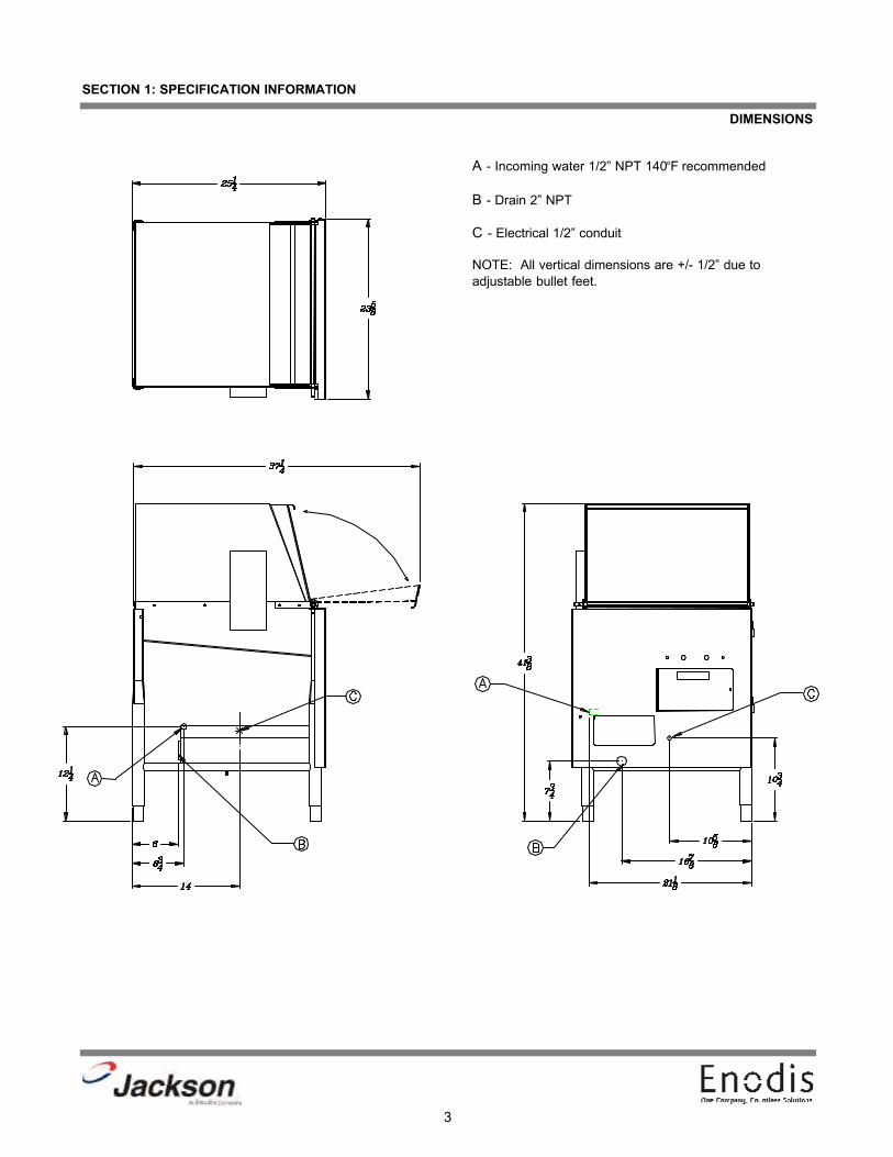
DIMENSIONS
A - Incoming water 1/2” NPT 140°F recommended
B - Drain 2” NPT
C - Electrical 1/2” conduit
NOTE: All vertical dimensions are +/- 1/2” due toadjustable bullet feet.
3
SECTION 1: SPECIFICATION INFORMATION
4
SECTION 2:INSTALLATION/OPERATION
INSTRUCTIONS

5
SECTION 2: INSTALLATION/OPERATION INSTRUCTIONS
INSTALLATION INSTRUCTIONS
VISUAL INSPECTION: Before installing the unit, check the container and the machine for any damage. A damaged containercould be an indication of damage to the unit. If there is damage to both the container and the unit, DO NOT throw away thecontainer. The dishmachine has been inspected and packed at the factory with the expectation that it will arrive to you in new,undamaged condition. However, rough handling by carriers or others may damage the unit while in transit. If this situation doesoccur, do not return the unit to Jackson; instead contact the carrier and ask them to inspect the damage to the unit and to com-plete an inspection report. You must contact the carrier within 48 hours of receiving the machine. Also, contact the dealer youpurchased the machine through.
UNPACKING THE DISHMACHINE: Remove the machine from the container and inspect for any missing parts. If an itemappears to be missing, contact Jackson immediately to report it.
LEVEL THE DISHMACHINE: The dishmachine(s) covered in this manual are designed to operate on a level surface. Ensurethat the machine is level from side to side and from front to back; adjust the unit’s bullet feet as required. Failure to level thedishmachine may cause decreased washing performance.
PLUMBING THE DISHMACHINE: All plumbing connections must comply with all applicable local, state and national plumbingcodes. The plumber is responsible for flushing the incoming water line prior to connecting it to remove all foreign debris thatmay get trapped in the valves or cause an obstruction. Any valves that are fouled by matter left in the water line and the expens-es resulting are not the responsibility of the manufacturer.
CONNECTING THE DRAIN LINE: The Delta 5 drain requires a minimum 2” NPT piping that is pitched at least 1/4” per foot.There must also be an air gap between the machine drain line and the floor sink or drain. If a grease trap is required by code,it should have a flow capacity of 5 gallons per minute.
WATER SUPPLY CONNECTION: Install the water supply line (1/2” IPS minimum) to the dishmachine line strainer using cop-per pipe. It is recommended that a water shut-off valve be installed between the main supply and the machine to allow for ser-vice. The water supply line must be capable of 20 ±5 PSI “flow” pressure at the recommended temperature as indicated onthe data plate.
In areas where the water pressure fluctuates or is greater than the recommended pressure, it is suggested that a water pres-sure regulator be installed. The Delta 5 does not come with a water pressure regulator as standard equipment.
It is also recommended that a shock absorber (not supplied with the DELTA 5) be installed in the incoming water line. This pre-vents line hammer (hydraulic shock), induced by the solenoid valve, which can cause damage to the equipment.
PLUMBING CHECK: Slowly turn on the water supply to the machine after connecting the incoming fill line and drain line. Checkfor leaks and repair as required. Leaks must be repaired prior to placing the machine in operation.

6
SECTION 2: INSTALLATION/OPERATION INSTRUCTIONS
ELECTRICAL POWER CONNECTION
ELECTRICAL POWER CONNECTION: Electrical and grounding connections must comply with all applicable portions of theNational Electric Code (ANSI/NFPA 70) and/or other electrical codes that may apply.
Disconnect the electrical power supply and place a safety tag at the disconnect switch to indicate that you are working on thecircuit.
The dishmachine data plate is located on the left front corner of the machine. Refer to this data plate for information concern-ing the unit’s specific electrical requirements.
To install the incoming power lines, open the connection box by removing the connection box lid. Install 1/2” conduit into thepre-punched holes in the back of the connection box. Route the power wires and connect to the power block and groundinglug. Install the service wires (L1 and N) to the appropriate terminals as they are marked on the terminal block. Install the ground-ing wire into the lug provided. Wires should be firmly secured in place. It is recommended that “De-Ox” or another similar anti-oxidation agent be used on all voltage connections.
VOLTAGE CHECK: Ensure that the machine is off and apply power to the machine. Check the incoming power at the termi-nal block and ensure it corresponds to the voltage on the machine data plate. Do not run the dishmachine if the voltage is toohigh or too low. Shut off the service breaker and mark it as being for the dishmachine. Advise all personnel of the location ofthe service breaker. Replace all covers and tighten the screws.
NOTE: Always refer to the machine data plate for specific electrical and water requirements. The material provided onthis page is for reference only and may be subject to change without notice.
WARNING: This equipment is not recommend for use with deionized water or other aggressive fluids. Use ofdeionized water or other aggressive fluids will result in corrosion and failure of materials and components. Use
of deionized water or other aggressive fluids will void the manufacturer's warranty.
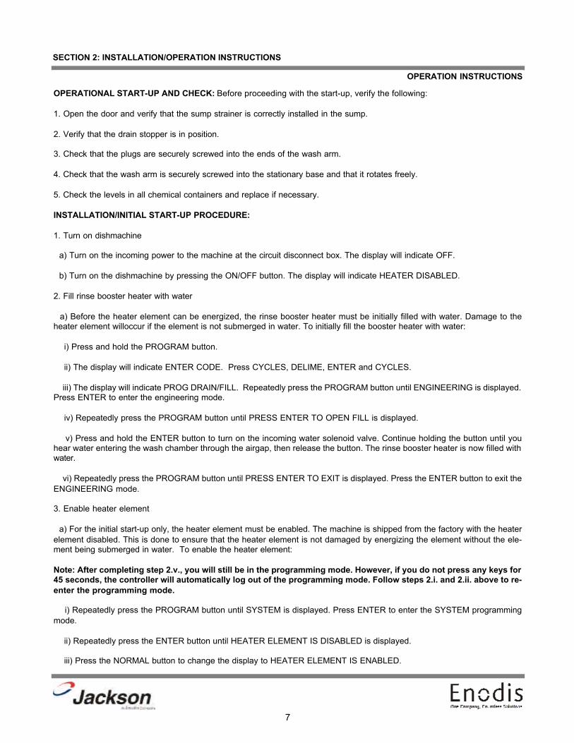
OPERATIONAL START-UP AND CHECK: Before proceeding with the start-up, verify the following:
1. Open the door and verify that the sump strainer is correctly installed in the sump.
2. Verify that the drain stopper is in position.
3. Check that the plugs are securely screwed into the ends of the wash arm.
4. Check that the wash arm is securely screwed into the stationary base and that it rotates freely.
5. Check the levels in all chemical containers and replace if necessary.
INSTALLATION/INITIAL START-UP PROCEDURE:
1. Turn on dishmachine
a) Turn on the incoming power to the machine at the circuit disconnect box. The display will indicate OFF.
b) Turn on the dishmachine by pressing the ON/OFF button. The display will indicate HEATER DISABLED.
2. Fill rinse booster heater with water
a) Before the heater element can be energized, the rinse booster heater must be initially filled with water. Damage to theheater element willoccur if the element is not submerged in water. To initially fill the booster heater with water:
i) Press and hold the PROGRAM button.
ii) The display will indicate ENTER CODE. Press CYCLES, DELIME, ENTER and CYCLES.
iii) The display will indicate PROG DRAIN/FILL. Repeatedly press the PROGRAM button until ENGINEERING is displayed.Press ENTER to enter the engineering mode.
iv) Repeatedly press the PROGRAM button until PRESS ENTER TO OPEN FILL is displayed.
v) Press and hold the ENTER button to turn on the incoming water solenoid valve. Continue holding the button until youhear water entering the wash chamber through the airgap, then release the button. The rinse booster heater is now filled withwater.
vi) Repeatedly press the PROGRAM button until PRESS ENTER TO EXIT is displayed. Press the ENTER button to exit theENGINEERING mode.
3. Enable heater element
a) For the initial start-up only, the heater element must be enabled. The machine is shipped from the factory with the heaterelement disabled. This is done to ensure that the heater element is not damaged by energizing the element without the ele-ment being submerged in water. To enable the heater element:
Note: After completing step 2.v., you will still be in the programming mode. However, if you do not press any keys for45 seconds, the controller will automatically log out of the programming mode. Follow steps 2.i. and 2.ii. above to re-enter the programming mode.
i) Repeatedly press the PROGRAM button until SYSTEM is displayed. Press ENTER to enter the SYSTEM programmingmode.
ii) Repeatedly press the ENTER button until HEATER ELEMENT IS DISABLED is displayed.
iii) Press the NORMAL button to change the display to HEATER ELEMENT IS ENABLED.
7
SECTION 2: INSTALLATION/OPERATION INSTRUCTIONS
OPERATION INSTRUCTIONS

8
SECTION 2: INSTALLATION/OPERATION INSTRUCTIONS
OPERATION INSTRUCTIONS (CONTINUED)
iv) Press the PROGRAM key to exit the SYSTEM programming mode. You should hear the heater contactor close.
v) Repeatedly press the PROGRAM button until EXIT is displayed. Press the ENTER button to exit the programming mode.
vi) The display will indicate HEATING WATER.
4. Adjust dishmachine fill level
a) Once the temperature in the rinse booster heater has reached its preset value, the incoming water solenoid valve will opento fill the wash tank with water (FILLING and the time remaining for the will be displayed during the fill sequence).
b) The display will then indicate OPEN DOOR.
c) Open the door and observe the water level in the wash tank sump. The water level should be between the two score lineson the drain stopper.
d) If the water level is not satisfactory, drain the sump by lifting the drain stopper. Close the door. Enter the programming modeand adjust the fill time as necessary (PROG DRAIN/FILL menu). Press the AUTO FILL button to refill the wash tank. Open thedoor and observe the water level. Repeat these steps until the proper water level is obtained.
5. Adjust dishmachine drain time
a) At the very end of the drain cycle, open the doors to interrupt the cycle. Observe the sump area. All water from the washcycle should be drained from the wash tank sump.
b) In the programming section, adjust the DRAIN time (PROG DRAIN/FILL menu) as necessary. Allow enough time for themachine to completely drain before the rinse begins. Avoid making the drain time too long, which will unnecessarily lengthenthe total cycle time.
6. Adjust dishmachine flush time
a) The FLUSH will use fresh water to rinse out the detergent residue and soils in the wash tank before the rinse begins. TheFLUSH time is the time that the drain valve will remain open at the beginning of the FILL cycle. Avoid making the flush timetoo long, which will increase the water usage per machine cycle.
b) In the programming section, increase or decrease the FLUSH time (PROG DRAIN/FILL menu) as necessary.
7. Measure and adjust chemical concentrations.
8. Check all water and drain fittings for leaks.
9. Instruct machine operators on proper cleaning and operating procedures.
GENERAL OPERATION SEQUENCE:
CAUTION: Water must be in the wash tank sump while the wash pump is running in order to avoid damage to thepump seal.
Close the machine's door. Turn on the machine by pressing the PUSH ON/OFF button on the front panel. The display will indi-cate HEATING WATER while the rinse water is heated in the booster heater. This heating may take several minutes, depend-ing on how long the machine has set idle.
When the water in the booster heater reaches the specified temperature, the machine will automatically fill the wash sump withwater (FILLING and the time remaining for filling will be indicated on the display). The minimum water level should be betweenthe two score lines on the drain stopper. To adjust the water level, see programming instructions. During this initial fill, the deter-gent dispensing pump will run to dispense into the wash tank sump.

9
SECTION 2: INSTALLATION/OPERATION INSTRUCTIONS
OPERATION INSTRUCTIONS (CONTINUED)
The display will indicate OPEN DOOR. Open the door and insert a rack of soiled dishes. The display will indicate CLOSEDOOR. Close the door. The display will indicate PRESS START TO START CYCLE. At any time between cycles, the opera-tor can press select the NORMAL or HEAVY cycles by pressing the appropriate button on the keypad. The default cycle is thenormal cycle. When either of these cycle keys is pressed, the display will momentarily display the selection. The cycle will beginwhen the PUSH TO START button on the front panel is pressed.
At the start of the cycle, a PREWASH sequence is initiated and the wash pump is turned on. The length of this PREWASHsequence is 20 seconds. PREWASH and the time remaining will be displayed on the first line of the display. The TEMPERA-TURE of the wash water will be displayed on the second line of the display.
At the end of the prewash sequence, if the wash tank water temperature is less than 120°F, or if the HEAVY cycle has beenselected, the machine will drain the wash water, and refill the sump with fresh, heated water from the booster tank. The dis-play will indicate DRAINING, FLUSH and FILLING and will countdown the time remaining for each during these steps.Detergent will be dispensed during the filling sequence.
If the detergent dispensing time is longer than the fill time, the incoming water solenoid valve will be opened for one second atthe completion of the detergent dispensing, in order to flush out any remaining detergent from the air gap. No rinse aid or san-itizer are dispensed. At the end of the prewash sequence, if the temperature of the wash water is greater than 120°F and theNORMAL cycles was selected, these steps are skipped and control goes directly to the washing sequence.
During the washing sequence, the wash pump is turned on. WASHING and the time remaining will be displayed on the firstline of the display. The TEMPERATURE of the wash water will be displayed on the second line of the display. If the length ofthe DETERGENT WASH is longer than the length of DETERGENT PREWASH, the detergent dispenser pump will run for thedifference in these time values, dispensing additional detergent into the wash tank sump. The length of the wash cycle is 45seconds.
At the end of the wash cycle, if the temperature in the rinse booster tank has not reached 120°F (regardless of the rinse tanktemperature setting), the wash time will be extended until the 120°F is reached, or three minutes, whichever is shorter. The dis-play will indicate EXTENDED WASH.
At the completion of the wash cycle, the machine will drain the wash water, and refill the sump with fresh, heated water fromthe booster tank. The display will indicate DRAINING, FLUSH and FILLING and will countdown the time remaining for each dur-ing these steps. During the FILLING sequence, rinse aid and sanitizer are dispensed.
The rinsing sequence now begins.
RINSING and the time remaining will be displayed on the first line of the display. The TEMPERATURE of the rinse water willbe displayed on the second line of the display.
The completion of the rinse sequence is the end of the cycle, and the display will indicate OPEN DOOR. Detergent is now dis-pensed into the wash tank sump for the next wash cycle. Open the door, remove the clean dishes, load a rack of soiled dish-es, close the door and press the start button to start the next cycle. If the next cycle is started before the completion of thedetergent dispensing, the display will indicate DETERGENT DISPENSE, and countdown the time remaining until the cycle willautomatically begin.
If the door is opened at any time during a cycle, CLOSE DOOR will be displayed. The cycle will restart at the beginning of theprewash sequence when the door is closed again.
The cycle counter will only increment when cycles are fully completed. To display the number of cycles completed, betweencycles, press the CYCLES button on the keypad. Then number of NORMAL cycles completed will be displayed. Press theCYCLES button again to display the number of completed HEAVY cycles.
DETERGENT PREWASH - The run time of the detergent dispensing pump before the prewash sequence which controls theamount of detergent dispensed.
DETERGENT WASH - The run time of the detergent dispensing pump before the wash sequence which controls the amountof detergent dispensed.

10
SECTION 2: INSTALLATION/OPERATION INSTRUCTIONS
OPERATION INSTRUCTIONS (CONTINUED)
SANITIZER - The run time of the sanitizer dispensing pump before the rinse sequence which controls the amount of sanitizerdispensed.
RINSE TANK TEMPERATURE - When the water in the rinse water booster heater reaches this temperature value, the heatingelement will be turned off.
SHUTDOWN AND CLEANING: To turn off the machine, press the ON/OFF button. The machine will automatically drain(TURNING OFF will be displayed) and then will turn off (OFF will be displayed).
Remove, clean and install the lower wash arm.
Remove, clean and install the four upper spray nozzles.
Remove, clean and install the accumulator strainer.
PRIMING THE CHEMICAL DISPENSING PUMPS: To prime the chemical feeder pumps that dispense the detergent, rinse aidand sanitizer chemicals, press and hold the corresponding prime button on the keypad. The machine must be idle (betweencycles) for these prime buttons to be active.
DELIMING OPERATIONS: The DELTA 5 machine has a pre-programmed delime sequence which will lead the operatorthrough the steps required to properly delime the machine.
To begin, the machine must be OFF. Press and hold the DELIME button on the keypad. The machine will automatically fill withfresh water (FILLING will be indicated on the display). The display will then indicate to OPEN DOOR - ADD LIME-A-WAY (delim-ing chemical agent). Open the doors and add the delime chemical agent. The display will indicate CLOSE DOORS TO STARTDELIME. When the doors are closed, the wash pump will turn on to circulate the delime agent throughout the machine. At anytime, the doors can be opened in order to inspect the inside of the machine. The wash pump will restart when the doors areclosed. The display will indicate PRESS DELIME TO STOP CYCLE.

11
SECTION 2: INSTALLATION/OPERATION INSTRUCTIONS
PROGRAMMING INSTRUCTIONS
To access the programming mode, the machine must be ON, and idle (between cycles). Press and hold the PROGRAM but-ton on the keypad. The display will prompt to ENTER CODE. At this prompt, enter the keys corresponding to the access code.Once in the programming mode, the PROGRAM button is used to scroll between the programming categories, the ENTER but-ton is used to select a program section or parameter. To change the value of the parameter, use the HEAVY button to decreasethe value of the parameter, and the NORMAL button to increase the value. To confirm a change to a programmable vale, pressthe ENTER button. To abort or escape out of a change, press the PROGRAM button.
Once in the programming mode, if there have been no keypad inputs for approximately 45 seconds, the system will automati-cally exit out of the programming mode.
All time adjustments are in minutes and seconds (minutes:seconds).
The following parameters can be adjusted in the programming mode:
1. In the PROG(RAM) DRAIN/FILL section:
a) FILL TIME - Length of fill cycles. The minimum water level should be between the score lines of the drain stopper.
b) FLUSH TIME - Time of overlap between the drain and fill times.
c) DRAIN TIME - Time that the drain is open after the wash cycle.
2. In the PROG(RAM) CHEMICAL section:
a) DETERGENT PREWASH - The run time of the detergent dispensing pump before the prewash sequence which controlsthe amount of detergent dispensed.
b) DETERGENT WASH - The run time of the detergent dispensing pump before the wash sequence which controls the amountof detergent dispensed.
c) RINSE AID - The run time of the rinse aid dispensing pump before the rinse sequence which controls the amount of rinseaid dispensed.
d) SANITIZER - The run time of the sanitizer dispensing pump before the rinse sequence which controls the amount of san-itizer dispensed.
3. In the SYSTEM section:
a) ENABLE/DISABLE HEATER ELEMENT - Selects whether or not the rinse water booster element can be energized. Theselection options are ENABLE or DISABLE.
b) RINSE TANK TEMPERATURE - When the water in the rinse water booster heater reaches this temperature value, the heat-ing element shall be turned off.
c) DISPLAY IN FAHRENHEIT OR CELSIUS - Selects the unit of measure for water temperature display.
4. The ENGINEERING section is used when trouble-shooting problems with the machine. In the ENGINEERING section:
a) TOTAL WASH CYCLES - This counter accumulates the total number of cycles which the machine has been run. It is a totalof all wash cycles and it cannot be reset.
b) PRESS ENTER TO:
i) RUN PUMP - Press and hold the ENTER button to run the wash pump motor. Release the ENTER button to make it stop.
ii) OPEN DRAIN - Press and hold the ENTER button to energize (open) the drain solenoid. Release the ENTER button tode-energize the solenoid.

12
SECTION 2: INSTALLATION/OPERATION INSTRUCTIONS
PROGRAMMING INSTRUCTIONS (CONTINUED)
iii) OPEN FILL - Press and hold the ENTER button to energize (open) the fill water valve solenoid. Release the ENTER but-ton to de-energize the solenoid.
iv) EXIT - Press the ENTER button to exit the ENGINEERING section.
5. RESET CYCLES - The system will prompt CLEAR COUNT(S)? E(YES) or P(NO) to confirm the that the cycle counter is tobe reset. Press the ENTER button on the keypad to reset the counter or press the PROGRAM button to exit without resettingthe counter.
6. EXIT - Press the ENTER button on the keypad to exit the programming mode.

Press and hold PROGRAM (P) for 2 seconds.
PROG DRAIN/FILL FILL TIME 0:07 FLUSH TIME 0:03 DRAIN TIME 0:06
PROG CHEMICAL DETERGENT 0:05PREWASH
DETERGENT 0:05WASH
RINSE AID 0:05 SANITIZER 0:05
SYSTEM
RESET COUNTS CLEAR COUNTS?
EXIT
CODE****
Press UP ARROW (NORMAL) to increase time settings
Press DOWN ARROW (HEAVY) to decrease time
Press CYCLES, DELIME, ENTER, CYCLES
Press ENTER Press ENTER Press ENTER
Press PROGRAM Press ENTER Press ENTER
Press ENTER
Press PROGRAM
Press PROGRAM
Press PROGRAM
Short Version
Refer to IO manual for system programming
Press ENTER Press ENTER to clear counter back to zero
Back to regular operation
Press ENTER
Press ENTER
13
SECTION 2: INSTALLATION/OPERATION INSTRUCTIONS
PROGRAMMING CHART FOR THE DELTA 5
14
SECTION 3:PREVENTATIVE MAINTENANCE

15
SECTION 3: PREVENTATIVE MAINTENANCE
PREVENTATIVE MAINTENANCE
The dishmachines covered in this manual are designed to operate with a minimum of interaction with the operator. However,this does not mean that some items will not wear out in time. Jackson highly recommends that any maintenance and repairsnot specifically discussed in this manual should be performed by QUALIFIED SERVICE PERSONNEL ONLY. Performing main-tenance on your dishmachine may void your warranty if it is still in effect, so if you have a question or concern, do not hesitateto contact a QUALIFIED SERVICE AGENCY.
There are many things that operators can do to prevent catastrophic damage to the dishmachine. One of the major causes ofcomponent failure has to do with prescrapping procedures. A dishmachine is not a garbage disposal; any large pieces of mate-rial that are put into the machine shall remain in the machine until they are either broken up (after spreading out on your ware!)or physically removed. Strainers are installed to help catch debris, but they do no good of they are clogged. Have operatorsregularly inspect the pan strainers to ensure (1) that they are free of soil and debris and (2) they are laying flat in the tub.
When cleaning out strainers, do NOT beat them on waste cans. The strainers are made of metal and can be forgiving; but oncesevere damage is done, it is next to impossible for the strainer to work in the way it was designed to. Wipe out strainers witha rag and rinse under a faucet if necessary. For stubborn debris, a toothpick should be able to dislodge any obstructions fromthe perforations. Always ensure that strainers are placed back in the machine before operation and that they lay flat in the tub.
Again, it is important to remind operators that trying to perform corrective maintenance on the dishmachine could lead to larg-er problems or even cause harm to the operator. If a problem is discovered; secure the dishmachine using proper shut downprocedures as listed in this manual and contact a QUALIFIED SERVICE AGENCY.
Some problems, however, may having nothing to do with the machine itself and no amount of preventative maintanence isgoing to help. A common problem has to do with temperatures being too low. Verify that the water temperatures coming to yourdishmachine match the requirements listed on the machine data plate. There can be a variety of reasons why your water tem-perature could be too low and you should discuss it with a QUALIFIED SERVICE AGENCY to determine what can be done.
By following the operating and cleaning instructions in this manual, you should get the most efficient results from your machine.As a reminder, here are some steps to take to ensure that you are using the dishmachine the way it was designed to work:
1. Ensure that the water temperatures match those listed on the machine data plate.2. Ensure that all strainers are in place before operating the machine.3. Ensure that all wash and/or rinse arms are secure in the machine before operating.4. Ensure that drains are closed/sealed before operating.5. Remove as much soil from dishes by hand as possible before loading into racks.6. Do not overfill racks.7. Ensure that glasses are placed upside down in the rack.8. Ensure that all chemicals being injected to machine have been verified as being at the correct concentrations.9. Clean out the machine at the end of every workday as per the instructions in the manual.10. Always contact a QUALIFIED SERVICE AGENCY whenever a serious problem arises.11. Follow all safety procedures, whether listed in this manual or put forth by local, state or national codes/regulations.

16
SECTION 4:TROUBLESHOOTING

17
SECTION 4: TROUBLESHOOTING
TROUBLESHOOTING GUIDE
The Delta 5 dishmachine uses a microprocessor-based electronic controller to control function of the machine. The micro-processor is pre-programmed at the factory to run a machine that is installed in a typical application. A LCD display is used toindicate the status of the machine.
The electronic controller board with LCD display controls all timing functions. The controller board is connected to the interfaceboard. It sends signals to the interface board to turn components on and off. The remaining electrical control components inthe machine are connected to the interface board.
To aid in troubleshooting, the interface board contains six red LED (light emitting diodes). These diodes are illuminated when-ever the output signal to the corresponding control item is ON. The following example will illustrate the troubleshootingsequence that should be used for all electrical control components. The wash pump runs at the first sequence of every cycle.The LED corresponding to the wash pump motor contactor will be ON when the pump is to be On. If the LED is ON, and thepump motor is not running, measure the voltage at the pump motor contactor soil (when the LED is on, meaning voltage shouldbe applied to the coil from the interface board). If there is no voltage, then replace the interface board. If there is voltage, thenthere is a problem in the pump motor and pump motor contactor. If the display indicates that the machine is in a wash cycle,and both the pump motor is not running and the LED is not ON, check the continuity of the cable that connects the controllerboard to the interface board. If continuity exists, replace the controller board. If the controller board has been replaced and theproblem still exists, replace the interface board.
The interface board contains six triacs, which are essentially electronic relays. Use a multimeter to verify that the interface boardoutput is supplying voltage to a control item (solenoid valve, peristaltic pump, motor contactor, etc.). During any troubleshoot-ing, it is critical to remember that a 120 volt signal will always be measured at the outputs of the interface board (pins 1 through8 on connector J4) if the corresponding load (solenoid valve, peristaltic pump, motor contactor, etc.) is not connected to theoutput. To avoid false readings, the control item that is being tested must be connected to the interface board output.
Drain LED
Pump LED
Fill LED
Sanitizer LED
Rinse Aid LED
Detergent Fill LED

18
SECTION 4: TROUBLESHOOTING
COMMON PROBLEMS
WARNING: Inspection, testing and repair of electrical equipment should be performed only by qualified service personnel.Certain procedures in this section require electrical tests or measurements while power is applied to the machine. Exerciseextreme caution at all times. If test points are not easily accessible, disconnect power, attach test equipment and reapply powerto test. When replacing electrical parts, disconnect power at source circuit breaker.
Problem: Machine will not run; no power to the unit.
1. Verify that the service disconnect or service breaker are not off.2. Verify that electrical service has been hooked to the machine.3. Verify that the correct voltage, phase and frequency have been hooked to the machine.4. Verify wiring of power switch to the schematic. Check continuity of switch. If switch is wired correctly, switch may needreplaced.5. Check the transformer for 24 Volts output.
Problem: Machine has power, but will not cycle.
1. Verify that the correct voltage, phase and frequency have been hooked to the machine.2. Faulty control board. Replace the control board.3. Check cycle switch for continuity.
Problem: Machine runs, but there is no water.
1. Verify that there is water connected to the machine and that it is turned on.2. If a strainer is placed in line with the machine, ensure that it is not clogged.3. Verify that there is 20 ±5 PSI of water flow pressure to the machine.4. Water fill valve may be faulty and may need to be replaced.
Problem: Machine runs and there is water, but dishes are dirty.
1. Ensure that good prescrapping occurs be removing as much heavy soil from the ware as possible before starting the cycle.2. Verify that chemical concentrations for detergent are correct for the given water conditions.3. Verify that the correct voltage, phase and frequency have been hooked to the machine.4. Verify that none of the wash or rinse arms have clogged nozzles.5. Ensure that the unit is filling to the correct water level.

19
SECTION 5:PARTS SECTION

20
SECTION 5: PARTS SECTION
CONTROL BOX ASSEMBLY
Control Box Base5700-002-40-03
12, 14 3 4
5, 156, 157, 158, 16911, 15 1012, 1413, 14

21
SECTION 5: PARTS SECTION
CONTROL BOX ASSEMBLY (CONTINUED)
ITEM QTY DESCRIPTION Mfg. No.1 1 Control Box Weldment 5700-002-45-722 1 Noise Filiter 5910-002-20-373 1 Interface Board 6680-002-16-814 4 Circuit Board Holder 5940-002-21-875 1 Inner Control Panel 5700-002-21-716 1 Terminal Strip 5940-002-78-977 1 Bracket, Fuse Strip Assembly 5700-002-42-608 1 6 Pole Fuse Holder 5920-002-42-139 1 Fuse, 3 amp 5920-002-44-1210 5 Fuse, 1.5 amp 5940-002-42-15-11 1 Motor Contactor 5945-109-05-6912 1 Relay 5945-002-45-2013 1 Transformer 115V to 24V 5950-002-16-7814 6 Locknut, 6-32 S/S Hex with Nylon Insert 5310-373-03-0015 8 Locknut, 10-24 S/S Hex with Nylon Insert 5310-373-01-0016 2 Screw, 6-32 x 3/8’’ Round Head 5305-171-02-0017* 1 Harness Assembly 5700-002-93-4818* 1 Assembly, Cable 5700-002-16-7719* 1 Temperature Probe 6680-002-16-8020* 1 Cable Assembly, Control Box to Connection Box 5700-002-45-7621* 1 Conduit Nipple, 1/2’’ Bushed 5975-002-51-8122* 1 Locknut, Conduit 1/2’’ 5975-002-51-8223* 1 Fitting, 1/2’’ Staight Plastic 5975-011-45-1324* 1 Connector, 1/2’’, 90° Metal 5975-111-01-0025* 1 Fitting, .231 x .394 5975-011-49-0326* 1 Fitting, Nut & Cap 5975-205-43-00* Represents an item not shown.
22
SECTION 5: PARTS SECTION
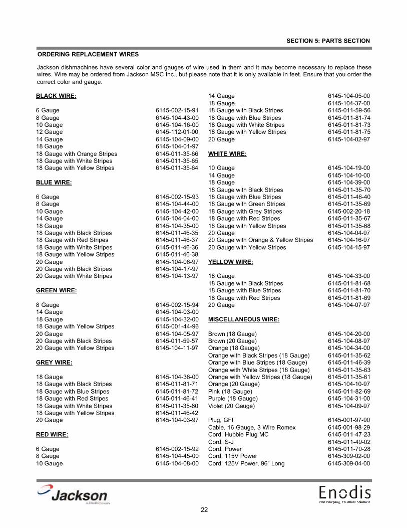
ORDERING REPLACEMENT WIRES
Jackson dishmachines have several color and gauges of wire used in them and it may become necessary to replace thesewires. Wire may be ordered from Jackson MSC Inc., but please note that it is only available in feet. Ensure that you order thecorrect color and gauge.
BLACK WIRE:
6 Gauge 6145-002-15-918 Gauge 6145-104-43-0010 Gauge 6145-104-16-0012 Gauge 6145-112-01-0014 Gauge 6145-104-09-0018 Gauge 6145-104-01-9718 Gauge with Orange Stripes 6145-011-35-6618 Gauge with White Stripes 6145-011-35-6518 Gauge with Yellow Stripes 6145-011-35-64
BLUE WIRE:
6 Gauge 6145-002-15-938 Gauge 6145-104-44-0010 Gauge 6145-104-42-0014 Gauge 6145-104-04-0018 Gauge 6145-104-35-0018 Gauge with Black Stripes 6145-011-46-3518 Gauge with Red Stripes 6145-011-46-3718 Gauge with White Stripes 6145-011-46-3618 Gauge with Yellow Stripes 6145-011-46-3820 Gauge 6145-104-06-9720 Gauge with Black Stripes 6145-104-17-9720 Gauge with White Stripes 6145-104-13-97
GREEN WIRE:
8 Gauge 6145-002-15-9414 Gauge 6145-104-03-0018 Gauge 6145-104-32-0018 Gauge with Yellow Stripes 6145-001-44-9620 Gauge 6145-104-05-9720 Gauge with Black Stripes 6145-011-59-5720 Gauge with Yellow Stripes 6145-104-11-97
GREY WIRE:
18 Gauge 6145-104-36-0018 Gauge with Black Stripes 6145-011-81-7118 Gauge with Blue Stripes 6145-011-81-7218 Gauge with Red Stripes 6145-011-46-4118 Gauge with White Stripes 6145-011-35-6018 Gauge with Yellow Stripes 6145-011-46-4220 Gauge 6145-104-03-97
RED WIRE:
6 Gauge 6145-002-15-928 Gauge 6145-104-45-0010 Gauge 6145-104-08-00
14 Gauge 6145-104-05-0018 Gauge 6145-104-37-0018 Gauge with Black Stripes 6145-011-59-5618 Gauge with Blue Stripes 6145-011-81-7418 Gauge with White Stripes 6145-011-81-7318 Gauge with Yellow Stripes 6145-011-81-7520 Gauge 6145-104-02-97
WHITE WIRE:
10 Gauge 6145-104-19-0014 Gauge 6145-104-10-0018 Gauge 6145-104-39-0018 Gauge with Black Stripes 6145-011-35-7018 Gauge with Blue Stripes 6145-011-46-4018 Gauge with Green Stripes 6145-011-35-6918 Gauge with Grey Stripes 6145-002-20-1818 Gauge with Red Stripes 6145-011-35-6718 Gauge with Yellow Stripes 6145-011-35-6820 Gauge 6145-104-04-9720 Gauge with Orange & Yellow Stripes 6145-104-16-9720 Gauge with Yellow Stripes 6145-104-15-97
YELLOW WIRE:
18 Gauge 6145-104-33-0018 Gauge with Black Stripes 6145-011-81-6818 Gauge with Blue Stripes 6145-011-81-7018 Gauge with Red Stripes 6145-011-81-6920 Gauge 6145-104-07-97
MISCELLANEOUS WIRE:
Brown (18 Gauge) 6145-104-20-00Brown (20 Gauge) 6145-104-08-97Orange (18 Gauge) 6145-104-34-00Orange with Black Stripes (18 Gauge) 6145-011-35-62Orange with Blue Stripes (18 Gauge) 6145-011-46-39Orange with White Stripes (18 Gauge) 6145-011-35-63Orange with Yellow Stripes (18 Gauge) 6145-011-35-61Orange (20 Gauge) 6145-104-10-97Pink (18 Gauge) 6145-011-82-69Purple (18 Gauge) 6145-104-31-00Violet (20 Gauge) 6145-104-09-97
Plug, GFI 6145-001-97-90Cable, 16 Gauge, 3 Wire Romex 6145-001-98-29Cord, Hubble Plug MC 6145-011-47-23Cord, S-J 6145-011-49-02Cord, Power 6145-011-70-28Cord, 115V Power 6145-309-02-00Cord, 125V Power, 96” Long 6145-309-04-00

23
SECTION 5: PARTS SECTION
ORDERING REPLACEMENT CONDUIT, HOSES & TUBING
Jackson dishmachines come with a wide variety of conduit and fittings for use in routing the wires of the machine. The list belowprovides for most of stock of such items. When ordering, remember that Jackson does not offer pre-cut sections of conduit foryour machine, instead it is sold by the foot. Please take into account the slack that will be necessary once installing the newconduit to ensure that it fits correctly. It is recommended that you order at least 6” more conduit than you require to ensure thatyou have enough for trimming. Tubing and hose are ordered by the foot. Jackson MSC Inc. reserves the right to require mini-mum ordering quantities for the items below.
CONDUIT:
Conduit, 1/2”, Liquidtite 5975-101-25-00Conduit, 1/2”, Non-Metallic 5975-111-46-57Conduit, 1/2”, PVC 5975-105-04-00Conduit, 1/2”, Sealtite 5975-105-01-00Conduit, 1/2”, Xtraflex 5975-105-06-44Conduit, 3/8”, Liquidtite 5975-105-02-00Conduit, 3/4”, Cole-Flex 5975-105-05-00Conduit, 3/4”, Liquidtite 5975-105-03-00Conduit, 3/4”, Non-Metallic 5975-011-47-71Conduit, 3/4” Xtraflex 5975-105-07-44Conduit, 1”, Carlon 5975-011-68-42
CONDUIT FITTINGS:
Elbow, Cole-Flex, 1/2”, 90° 5975-205-40-00Elbow, Xtraflex, 1/2”, 90° 5975-205-44-44Elbow, Xtraflex, 3/4”, 90° 5975-205-45-44Fitting, 1/2” Straight 5975-011-45-13Fitting, 1/2”, Straight, Zinc Plated 5975-111-89-89Fitting, 1/2”, 45° 5975-011-45-23Fitting, 1/2”, 45°, Zinc Plated 5975-111-89-86Fitting, 1/2”, 90° 5975-011-45-14Fitting, 1/2”, 90°, Zinc Plated 5975-111-89-88Fitting, 3/4”, Straight 5975-011-47-72Fitting, 3/4”, 45° 5975-011-47-74Fitting, 3/4”, 90° 5975-011-47-73Fitting, 1”, Straight 5975-011-70-75Fitting, 1”, 90° 5975-011-68-43Fitting, Cole-Flex, 1/2” Straight 5975-205-03-00Fitting, Cole-Flex, 3/4” Straight 5975-205-41-00Fitting, Cole-Flex, 3/4”, 90° 5975-204-42-00Fitting, Liquidtite, .231 ID/.394 OD 5975-011-49-03Fitting, Liquidtite, .25 ID/.546 OD 5975-011-65-51Fitting, Liquidtite, .27 ID/.48 OD 5975-011-59-50Fitting, Liquidtite, 1/2”, 90° 5975-111-01-00Fitting, Liquidtite, 3/8”, Straight 5975-205-03-82Fitting, Liquidtite, 3/8”, 90° 5975-205-02-82Fitting, Liquidtite, 3/4”, Straight 5975-205-15-02Fitting, Liquidtite, 3/4”, 45° 5975-205-01-82Fitting, Liquidtite, 3/4”, 90° 5975-205-07-82Fitting, Xtraflex, 1/2”, Straight 5975-205-47-44Fitting, Xtraflex, 3/4”, Straight 5975-205-46-44Nut, 1-1/4” 5975-011-42-54
HOSE:
Hose, 3/16” ID x 5/16” OD 4720-601-40-00Hose, 1/4” ID x .062” Wall, Excelon 4720-111-59-46Hose, 1/4” ID x 1/2” OD, 300-350 4720-011-95-43Hose, 3/8” ID x 5/8” OD, 300 PSI 4720-002-31-63Hose, 3/8” ID x 5/8” OD, PVC 4720-011-35-41Hose, 3/8” ID x 3/4” OD, PVC 4720-111-35-41Hose, 1/2” ID x 3/4” OD 4720-011-94-01Hose, 1/2” ID, Reinforced 4720-011-63-06Hose, 5/8” ID x 7/8” OD, PVC 4720-601-14-00Hose, 3/4” ID x 1” OD 4720-011-94-10Hose, 3/4” ID, Nylon Reinforced 4720-011-63-02Hose, 1” ID x 1-1/4” OD, EPDM 4720-111-39-73Hose, 1 1/4” ID x 1 1/2” OD 4720-601-42-00Hose, 1 1/4” ID, Reinforced 4720-011-44-47Hose, 1 1/2” ID, Clear Wire 4720-111-34-60Hose, 2” ID, Nylon Reinforced 4720-011-63-25Hose, 2” ID, Reinforced Flex Drain 4720-011-63-04Hose, 2” ID x 3” OD, EPDM 4720-011-88-02
TUBING:
Tubing, 1/8” OD, Paraflex 4720-111-58-09Tubing, 3/16” ID x .54” OD, CPVC 4720-111-35-31Tubing, 1/4” OD 4720-111-51-65Tubing, 1/4” OD, Blue 4720-601-11-00Tubing, 1/4” OD, Red 4720-601-12-00Tubing, 1/4” OD, White 4720-601-13-00Tubing, 1/4” OD, Paraflex 4720-111-51-70Tubing, 1/4” ID x 3/8” OD, Tygon 4720-001-97-65Tubing, 1/2” ID x 13/16” OD, Poly 4720-601-24-00Tubing, 5/16” x 7/16” OD, Clear 4720-111-35-34Tubing, 5/16” ID x 1/2” OD, Flex 4720-011-35-21Tubing, 3/8” ID x 1/16” Wall, Clear 4720-601-22-00Tubing, 3/8” OD, White Poly 4720-011-50-49Tubing, 5/8” ID with .125” Wall 4720-002-12-20Tubing, 3/4” ID x 1/8” Wall, Poly 4720-601-25-00Tubing, 3/4” ID x 1-1/8” OD, Nylon 4720-001-84-01Tubing, 1” Polybrade 4720-011-69-16Tubing, 1” ID x 1-3/8” OD, Poly 4720-601-23-00Tubing, 1 1/2” Polybrade 4720-011-69-17

24
SECTION 5: PARTS SECTION
CONTROL BOX COVER ASSEMBLY
ITEM QTY DESCRIPTION Mfg. No.1 1 Control Box Cover 5700-002-40-002 2 Motor Chemical Feeder Pump, 36 RPM 4320-111-35-143 1 Motor, Chemical Feeder Pump, 14 RPM 4320-111-35-134 1 Drip Channel 5700-002-40-655 1 Chemical Feeder Pump Kit 4320-121-37-106 1 Tubing, 1/4’’ OD x 120’’ Long, White 5700-011-37-137 1 Tubing, 1/4’’ OD x 120’’ Long, Red 5700-011-37-158 1 Tubing, 1/4’’ OD x 120’’ Long, Blue 5700-011-37-179 1 Tubing, 1/4’’ OD x 60’’ Long, Red 5700-011-63-1810 1 Tubing, 1/4’’ OD x 60’’ Long, Blue 5700-002-52-3411 1 Tubing, 1/4’’ OD x 60’’ Long, Blue 5700-002-52-3412* 1 Stiffener 5700-002-66-4913* 1 Decal, Detergent / Rinse Prime 9905-011-34-9514* 1 Decal, Sanitizer Prime 9905-011-34-9815* 1 Tygon Sight Tube 5700-011-34-91
1
2 2 3
4
5 5 5
6
7
8
9
10
11
* Represents an item not shown.

25
SECTION 5: PARTS SECTION
CHEMICAL FEEDER PUMP ASSEMBLY
Screw, 6-32 x 3/4” Phillips Pan Head4 per
5305-011-37-05
Roller, Red (Detergent/Sanitizer)4320-111-36-70
Roller, White (Rinse Aid)4320-002-82-28
Front Housing 4320-111-37-08
Rear Housing 4320-111-37-09
Squeeze Tube, Sanitizer(Use with the red roller.)
5700-002-44-33
queeze Tube, Detergent/Rinse Aid(Use with the white roller.)
5700-111-35-33
Screw, 8-32 x 1/2” Phillips Flat Head 2 per
5305-011-37-06
Motor, 14 RPM 115V Rinse Aid Feeder Pump
4320-111-35-13
Motor, 36 RPM 115V Detergent/Sanitizer Feeder Pump
4320-111-35-14
Screw, 8-32 x 3/8” Phillips Pan Head 2 per
5305-011-37-07
26
SECTION 5: PARTS SECTION
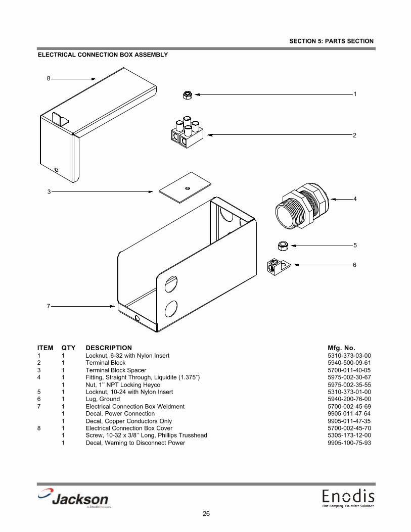
ELECTRICAL CONNECTION BOX ASSEMBLY
ITEM QTY DESCRIPTION Mfg. No.1 1 Locknut, 6-32 with Nylon Insert 5310-373-03-002 1 Terminal Block 5940-500-09-613 1 Terminal Block Spacer 5700-011-40-054 1 Fitting, Straight Through, Liquidite (1.375”) 5975-002-30-67
1 Nut, 1’’ NPT Locking Heyco 5975-002-35-555 1 Locknut, 10-24 with Nylon Insert 5310-373-01-006 1 Lug, Ground 5940-200-76-007 1 Electrical Connection Box Weldment 5700-002-45-69
1 Decal, Power Connection 9905-011-47-641 Decal, Copper Conductors Only 9905-011-47-35
8 1 Electrical Connection Box Cover 5700-002-45-701 Screw, 10-32 x 3/8’’ Long, Phillips Trusshead 5305-173-12-001 Decal, Warning to Disconnect Power 9905-100-75-93
1
2
34
5
6
7
8

27
SECTION 5: PARTS SECTION
FRAME WELDMENT/HOOD ASSEMBLY
To order the Bullet Feet4 per Frame Weldment
5340-002-14-55
1
2
3
4
5
9
6
7, 8
9
Frame Assembly5700-002-54-64
28
SECTION 5: PARTS SECTION
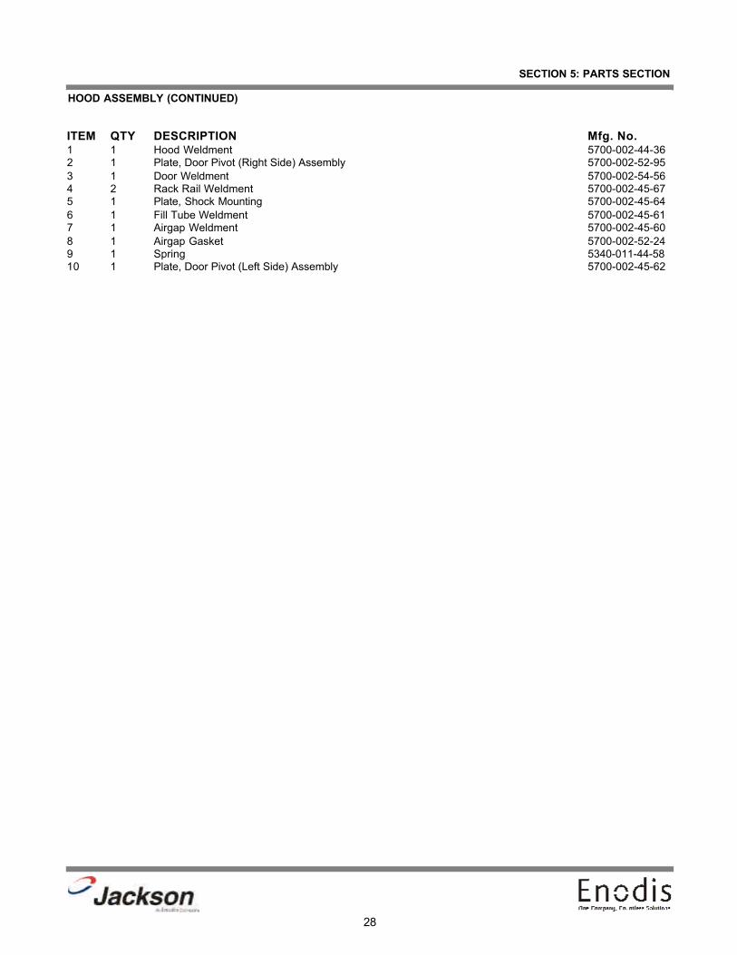
HOOD ASSEMBLY (CONTINUED)
ITEM QTY DESCRIPTION Mfg. No.1 1 Hood Weldment 5700-002-44-36 2 1 Plate, Door Pivot (Right Side) Assembly 5700-002-52-95 3 1 Door Weldment 5700-002-54-56 4 2 Rack Rail Weldment 5700-002-45-67 5 1 Plate, Shock Mounting 5700-002-45-646 1 Fill Tube Weldment 5700-002-45-617 1 Airgap Weldment 5700-002-45-608 1 Airgap Gasket 5700-002-52-249 1 Spring 5340-011-44-5810 1 Plate, Door Pivot (Left Side) Assembly 5700-002-45-62
29
SECTION 5: PARTS SECTION
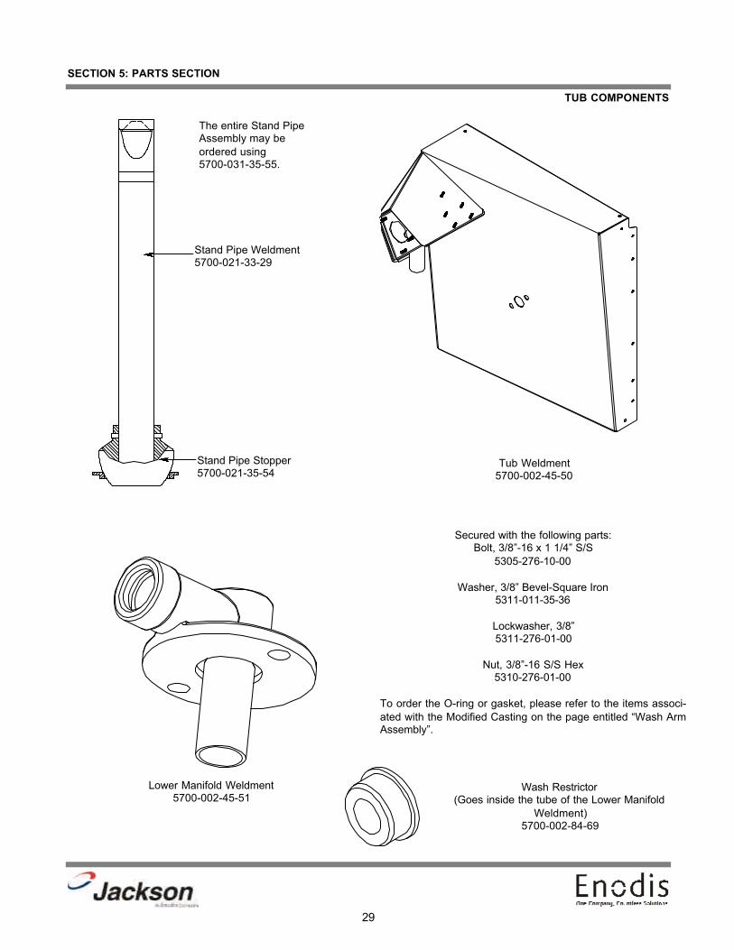
TUB COMPONENTS
Stand Pipe Weldment5700-021-33-29
Stand Pipe Stopper5700-021-35-54
The entire Stand PipeAssembly may beordered using 5700-031-35-55.
Tub Weldment5700-002-45-50
Lower Manifold Weldment5700-002-45-51
Secured with the following parts:Bolt, 3/8”-16 x 1 1/4” S/S
5305-276-10-00
Washer, 3/8” Bevel-Square Iron 5311-011-35-36
Lockwasher, 3/8”5311-276-01-00
Nut, 3/8”-16 S/S Hex5310-276-01-00
To order the O-ring or gasket, please refer to the items associ-ated with the Modified Casting on the page entitled “Wash ArmAssembly”.
Wash Restrictor(Goes inside the tube of the Lower Manifold
Weldment)5700-002-84-69

30
SECTION 5: PARTS SECTION
SPILLWAY WELDMENT ASSEMBLY/PUMP SUCTION HOSE
Spillway Weldment1 per machine
5700-031-37-86
Associated Hardware:Locknut, 1/4”-20 S/S Hex with Nylon
Insert 5310-374-01-00 Drain Seat Insert
1 per machine5700-021-34-38
Spillway Gasket2 per machine5700-111-34-52
Pump Suction Hose1 per machine
5700-002-40-82
To order the hose clamps for the Pump Suction Hose:Hose Clamp
4730-719-01-37
Hose Clamp 1 1/16” to 2 1/4”4730-719-18-00

31
SECTION 5: PARTS SECTION
WASH ARM ASSEMBLY
Wash Arm Weldment w/ End Plugs5700-021-46-58
Wash Arm Bearing Assembly5700-021-35-97
Modified Casting Wedge5700-002-45-06
Manifold Gasket5700-111-35-03
Manifold O-Ring5330-111-35-15
Complete Wash Arm assembly 5700-021-39-23

32
SECTION 5: PARTS SECTION
UPPER HALO ASSEMBLY
Upper Wash Halo Weldment1 per machine
5700-002-45-66
Clamp, Pipe 5/8”5700-000-35-06
Locknut, 1/4”-20 Hex with Nylon Insert5310-374-01-00
Spray Nozzle and Receptacle3 per machine
4730-002-55-61

33
SECTION 5: PARTS SECTION
DRAIN SOLENOID ASSEMBLY
Solenoid Box1 per machine
5700-002-40-69
DELTA 5 Solenoid Box Cover1 per machine
5700-002-40-70
Order the following associated parts with these part numbers:
Locknut, 10-24 with Nylon Insert 5310-373-01-00Decal, Warning 9905-100-75-93
The DELTA 5 drain solenoid and related hardware may be ordered using the following part numbers:
Drain Solenoid (115 Volt) 4810-200-11-00Locknut, 10-24 with Nylon Insert 5310-373-01-00
Drain Link1 per assembly
5700-002-40-83Nut, Hex, 5/16”-181 per assembly5310-275-01-00
Drain Link Connector1 per assembly5700-002-38-10
Order the entire Drain Link Assembly using 5700-002-45-52
Cotter Pin (Not Shown)1 per assembly5315-011-60-09
Drain Link Assembly
34
SECTION 5: PARTS SECTION
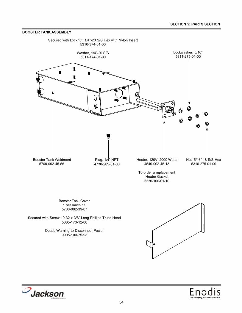
BOOSTER TANK ASSEMBLY
Booster Tank Weldment5700-002-45-56
Plug, 1/4” NPT4730-209-01-00
Heater, 120V, 2000 Watts4540-002-45-13
To order a replacementHeater Gasket
5330-100-01-10
Lockwasher, 5/16”5311-275-01-00
Nut, 5/16”-18 S/S Hex5310-275-01-00
Booster Tank Cover1 per machine
5700-002-39-07
Secured with Screw 10-32 x 3/8” Long Phillips Truss Head5305-173-12-00
Decal, Warning to Disconnect Power9905-100-75-93
Secured with Locknut, 1/4”-20 S/S Hex with Nylon Insert5310-374-01-00
Washer, 1/4”-20 S/S 5311-174-01-00
35
SECTION 5: PARTS SECTION
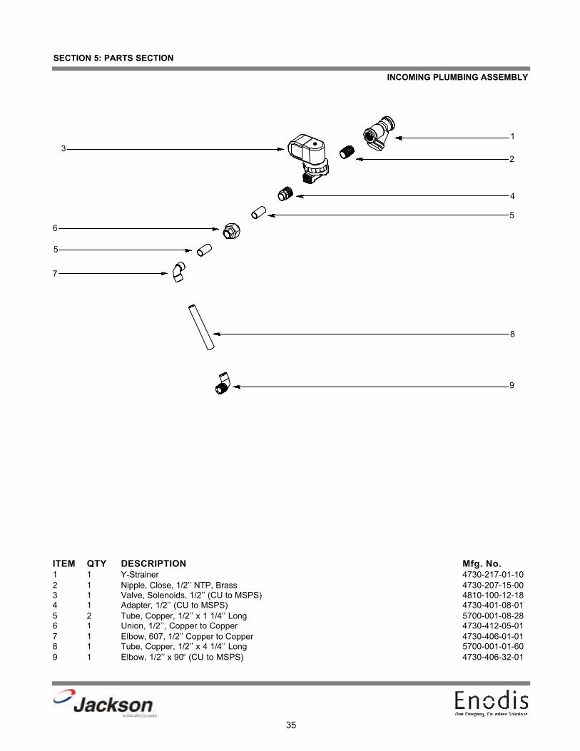
INCOMING PLUMBING ASSEMBLY
ITEM QTY DESCRIPTION Mfg. No.1 1 Y-Strainer 4730-217-01-102 1 Nipple, Close, 1/2’’ NTP, Brass 4730-207-15-003 1 Valve, Solenoids, 1/2’’ (CU to MSPS) 4810-100-12-184 1 Adapter, 1/2’’ (CU to MSPS) 4730-401-08-015 2 Tube, Copper, 1/2’’ x 1 1/4’’ Long 5700-001-08-286 1 Union, 1/2’’, Copper to Copper 4730-412-05-017 1 Elbow, 607, 1/2’’ Copper to Copper 4730-406-01-018 1 Tube, Copper, 1/2’’ x 4 1/4’’ Long 5700-001-01-609 1 Elbow, 1/2’’ x 90° (CU to MSPS) 4730-406-32-01
1
23
4
56
5
7
8
9

Screw
Data Plate
Coil & Housing
Valve BonnetSpring4810-200-04-18
Plunger4810-200-04-18
O-Ring4810-100-03-18Diaphragm
Retainer
Diaphragm4810-100-03-18
Screen Retainer
Mesh Screen
Valve Body
Complete 110 Volt Solenoid Valve Assembly4810-100-12-18
Coil & Housing only4810-200-01-18
36
SECTION 5: PARTS SECTION
1/2” SOLENOID VALVE REPAIR PARTS KIT

Pump Suction Hose5700-002-40-82
Discharge Tube Connector5700-011-70-34
Refer to Motor & PumpAssembly Page
Secured with Locknut, 1/4”-20 S/S Hex w/ Nylon Insert5310-374-01-00
Washer, 1/4”-20 S/S 5311-174-01-00
37
SECTION 5: PARTS SECTION
PUMP AND MOTOR ASSEMBLY
38
SECTION 5: PARTS SECTION
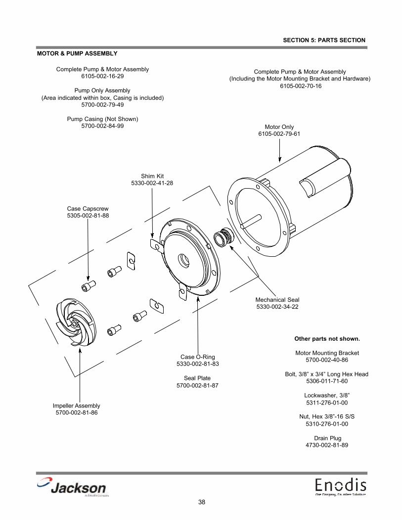
MOTOR & PUMP ASSEMBLY
Impeller Assembly5700-002-81-86
Mechanical Seal5330-002-34-22
Other parts not shown.
Motor Mounting Bracket5700-002-40-86
Bolt, 3/8” x 3/4” Long Hex Head5306-011-71-60
Lockwasher, 3/8”5311-276-01-00
Nut, Hex 3/8”-16 S/S5310-276-01-00
Drain Plug4730-002-81-89
Case O-Ring5330-002-81-83
Seal Plate5700-002-81-87
Case Capscrew5305-002-81-88
Motor Only6105-002-79-61
Complete Pump & Motor Assembly6105-002-16-29
Pump Only Assembly(Area indicated within box, Casing is included)
5700-002-79-49
Pump Casing (Not Shown)5700-002-84-99
Complete Pump & Motor Assembly (Including the Motor Mounting Bracket and Hardware)
6105-002-70-16
Shim Kit5330-002-41-28

39
SECTION 5: PARTS SECTION
BOOSTER TANK DISCHARGE HOSE/FILL TUBE WELDMENT ASSEMBLY
Fitting, 1/2” Pushlock, Female, Brass2 per assembly4730-011-93-99
Hose, 1/2” x 22 1/2” Long1 per assembly
5700-002-45-59
Order the entire Booster Tank Discharge Hose Assembly with5700-002-45-48.
Connects to the Incoming Plumbing Assemblywith a 1/2” NPT Brass Close Nipple:4730-207-15-00
Fill Tube Weldment1 per machine5700-002-45-61
Chemical Tube Grommet3 per assembly5325-002-42-65
FILL TUBE WELDMENT ASSEMBLY

40
SECTION 5: PARTS SECTION
STRAINERS
Accumulator Shell Weldment1 per machine
5700-002-51-95
Accumulator Strainer Weldment1 per machine
5700-002-45-54
Secured with Locknut, 1/4”-20 S/S Hex with Nylon Insert5310-374-01-00
Pump Intake Strainer1 per machine
5700-002-60-50

41
SECTION 5: PARTS SECTION
DOOR COMPONENTS
Door Pivot Plate Bearing5700-002-45-09
Door Pivot Plate Left Weldment5700-002-45-63
Door Pivot Plate Left AssemblyComplete Left Assembly
5700-002-45-62
Bolt, 1/4”-20 Eye, S/S5306-002-55-59
Shock Mounting Plate Weldment1 per machine
5700-002-45-64
Door Weldment1 per machine
5700-002-45-65
Secured with:Bolt, 1/4”-20 x 3/8”
5305-274-20-00
Washer, 1/4”-20 S/S 5311-174-01-00
Door Pivot Plate Right Assembly
Door Pivot Plate Bearing5700-002-45-09
Door Pivot Plate Right Weldment5700-002-52-94
Complete Right Assembly5700-002-52-95

42
SECTION 5: PARTS SECTION
FRONT PANEL ASSEMBLY
Light, Yellow Indicator5945-002-31-54
Switch, Apem5930-002-20-39
Switch, Apem5930-002-20-39
Light, Red Indicator5945-002-31-53
Secured with:Screw, 10-32 x 3/8” Long, Phillips Truss Head
5305-173-12-00
Front Panel Decal9905-002-45-88
Diecut, Front Panel Decal5700-002-46-72
43
SECTION 5: PARTS SECTION
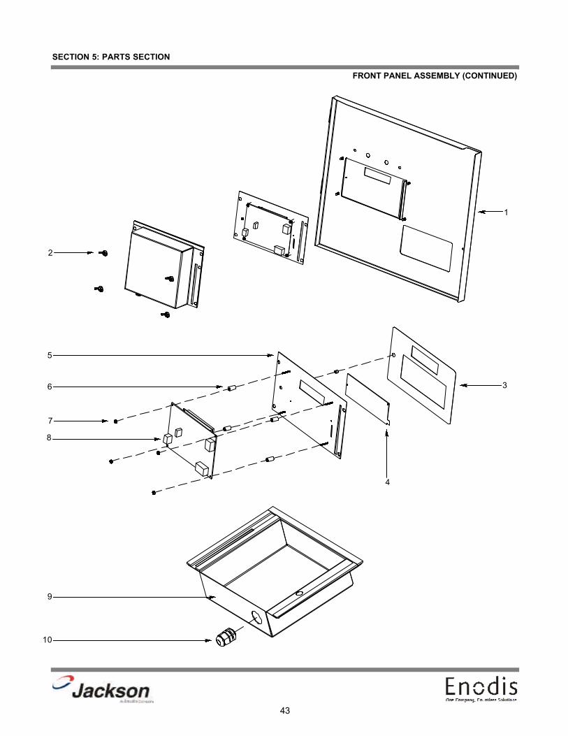
FRONT PANEL ASSEMBLY (CONTINUED)
1
2
3
4
5
6
7
8
9
10
44
SECTION 5: PARTS SECTION
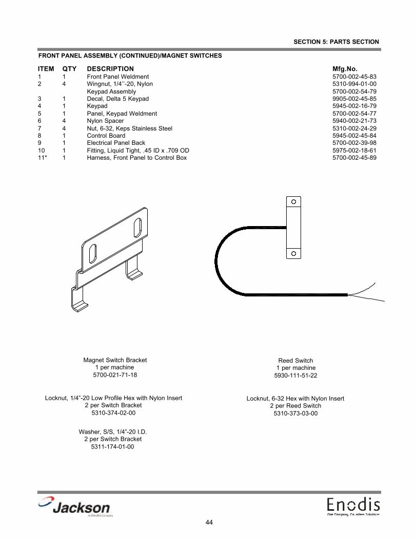
FRONT PANEL ASSEMBLY (CONTINUED)/MAGNET SWITCHES
ITEM QTY DESCRIPTION Mfg.No.1 1 Front Panel Weldment 5700-002-45-832 4 Wingnut, 1/4’’-20, Nylon 5310-994-01-00
Keypad Assembly 5700-002-54-793 1 Decal, Delta 5 Keypad 9905-002-45-854 1 Keypad 5945-002-16-795 1 Panel, Keypad Weldment 5700-002-54-776 4 Nylon Spacer 5940-002-21-737 4 Nut, 6-32, Keps Stainless Steel 5310-002-24-298 1 Control Board 5945-002-45-849 1 Electrical Panel Back 5700-002-39-9810 1 Fitting, Liquid Tight, .45 ID x .709 OD 5975-002-18-6111* 1 Harness, Front Panel to Control Box 5700-002-45-89
Magnet Switch Bracket1 per machine
5700-021-71-18
Reed Switch1 per machine
5930-111-51-22
Locknut, 6-32 Hex with Nylon Insert2 per Reed Switch
5310-373-03-00
Locknut, 1/4”-20 Low Profile Hex with Nylon Insert2 per Switch Bracket
5310-374-02-00
Washer, S/S, 1/4”-20 I.D.2 per Switch Bracket
5311-174-01-00

45
SECTION 5: PARTS SECTION
LEFT AND RIGHT SIDE PANEL ASSEMBLIES
Complete Right Side Panel Assembly5700-002-60-26
Right Side Panel 5700-002-59-96
Tape, 21 5/8” VHB 5700-002-60-29
Complete Left Side Panel Assembly5700-002-60-27
Left Side Panel5700-002-59-97
Tape, 7 1/4” VHB 5700-002-60-30
Tape, 1 1/2” VHB 5700-002-60-31
Tape, 6 1/4” VHB 5700-002-60-32
Grommet, Rubber 1/2” OD x .38 ID5325-011-46-73

46
SECTION 5: PARTS SECTION
8 - PIN HARNESS

47
SECTION 6:ELECTRICAL SCHEMATICS

48
SECTION 6: ELECTRICAL SCHEMATICS
DELTA 5 115 VOLT - 50/60 HERTZ - SINGLE PHASE